
Detectors - ridl.cfd.rit.edu
59
1 Detectors RIT Course Number 1051-465 Lecture Noise
Transcript of Detectors - ridl.cfd.rit.edu
1
Detectors
RIT Course Number 1051-465Lecture Noise
2
Aims for this lecture• learn to calculate signal-to-noise ratio• describe processes that add noise to a detector signal• give examples of how to combat noise
3
Lecture Outline• signal-to-noise ratio• noise sources
– shot noise• signal• dark current• background
– thermal noise (Johnson)– kTC– 1/f– read noise in the electronics (summation of many contributors)– electronic crosstalk– popcorn noise– pickup/interference
• how to combat noise, improving SNR
4
Introduction• The ability to detect an object in an image is related to the
amplitude of the signal and noise (and by contrast in some cases).
• The signal can be increased by collecting more photons, e.g.– building a bigger lens, – using more efficient optics, – having a more efficient detector.
• The noise can be reduced by making better electronics.

5
Signal-to-Noise Ratio
6
What is Signal? What is Noise?
7
SNR and Sensitivity Definitions• SNR is the ratio of detected signal to uncertainty of the signal
measurement. Higher is better.• Sensitivity is the flux level that corresponds to a given SNR
for a particular system and integration time. Lower is better.
8
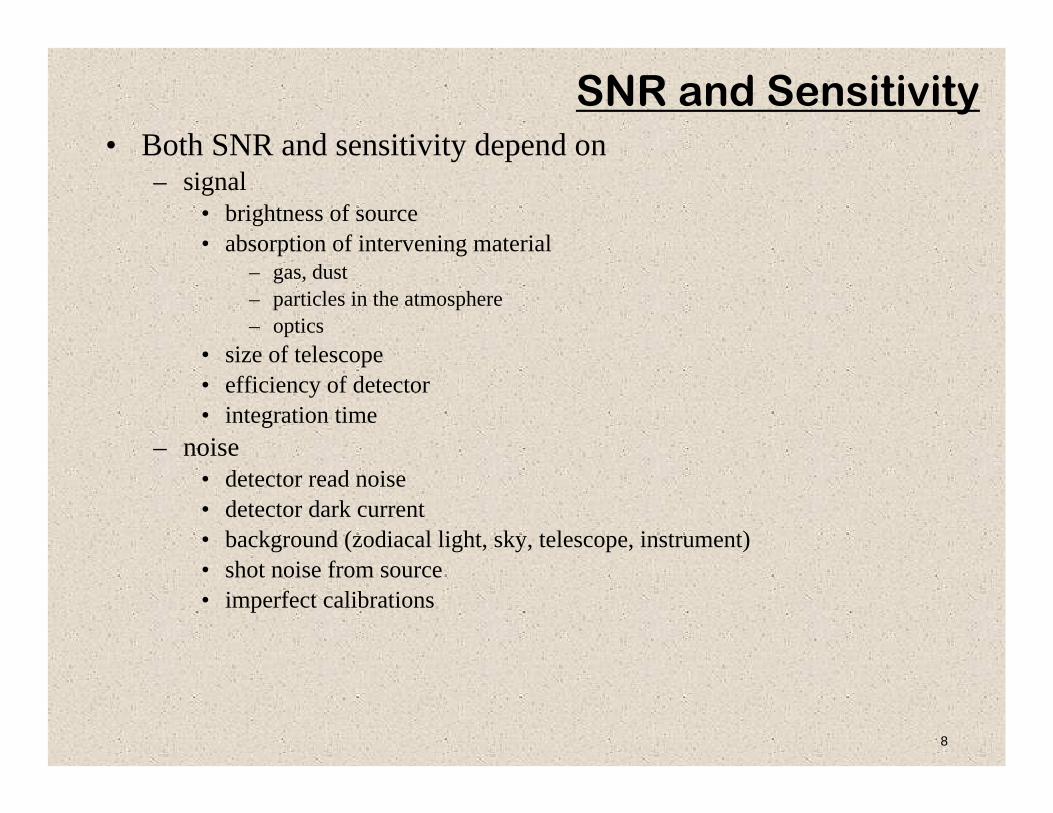
SNR and Sensitivity• Both SNR and sensitivity depend on
– signal• brightness of source• absorption of intervening material
– gas, dust– particles in the atmosphere– optics
• size of telescope • efficiency of detector• integration time
– noise• detector read noise• detector dark current• background (zodiacal light, sky, telescope, instrument)• shot noise from source• imperfect calibrations
9
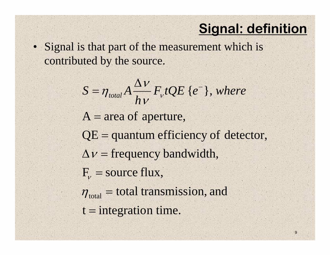
• Signal is that part of the measurement which is contributed by the source.
n time.integratiot and ion, transmisstotal
flux, sourceFbandwidth,frequency
detector, of efficiency quantumQE aperture, of areaA
},{
total
==
==Δ=
=
Δ= −
η
ν
ννη
ν
ν whereetQEFh
AS total
Signal: definition
10
.2∑=i
itotal NN
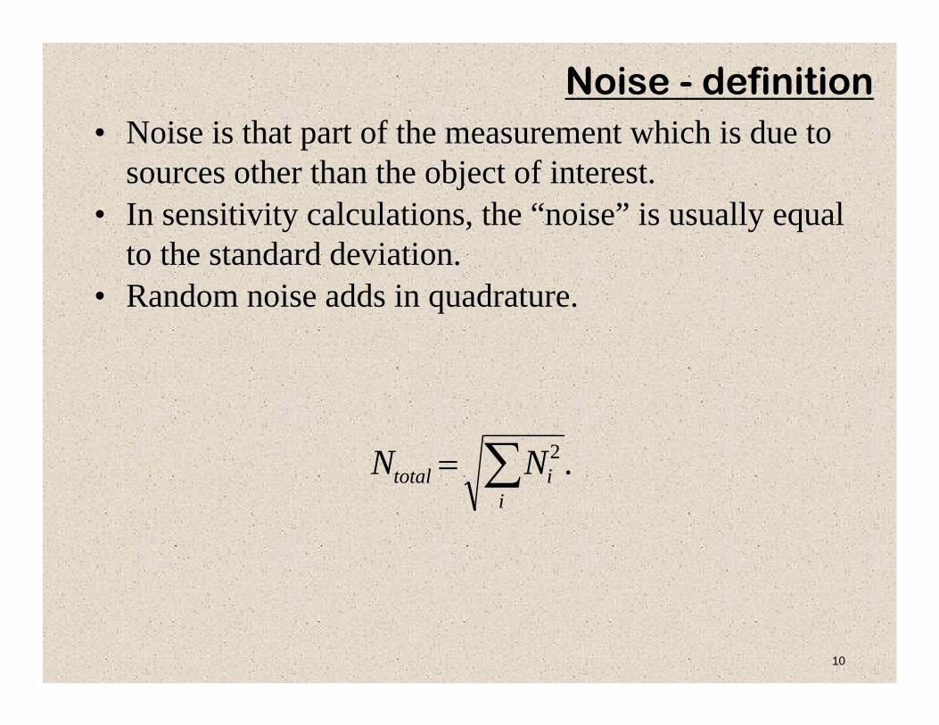
Noise - definition• Noise is that part of the measurement which is due to
sources other than the object of interest.• In sensitivity calculations, the “noise” is usually equal
to the standard deviation.• Random noise adds in quadrature.
11
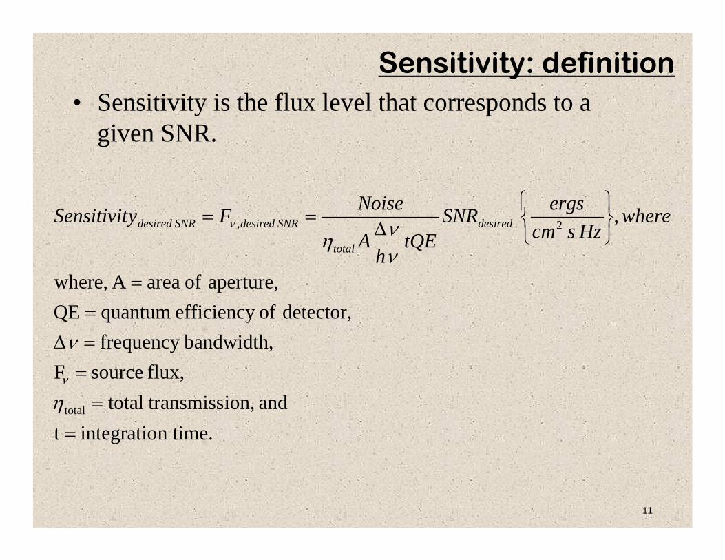
• Sensitivity is the flux level that corresponds to a given SNR.
n time.integratiot and ion, transmisstotal
flux, sourceFbandwidth,frequency
detector, of efficiency quantumQE aperture, of areaA where,
,
total
2,
==
==Δ=
=
⎭⎬⎫
⎩⎨⎧
Δ==
η
ν
ννη
ν
ν whereHzscm
ergsSNRtQE
hA
NoiseFySensitivit desired
total
SNRdesiredSNRdesired
Sensitivity: definition

12
SNR Example• These images show synthetic noise added to a real image of a star cluster obtained
using Keck/LGSAO.• The maximum signal has been normalized to 100 and shot noise has been added.
SNR values are for brightest pixel.SNR=10
read noise=0 e−SNR=9
read noise=5 e−SNR=7
read noise=10 e−
SNR=4read noise=20 e−
SNR=2read noise=50 e−
13
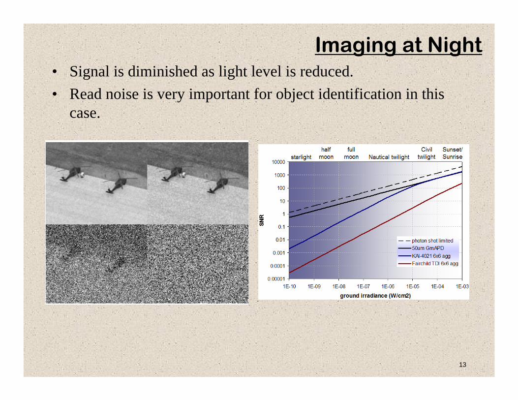
Imaging at Night• Signal is diminished as light level is reduced.• Read noise is very important for object identification in this
case.
14
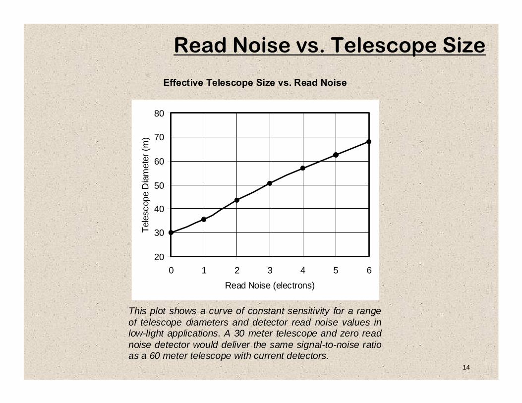
Read Noise vs. Telescope Size
Effective Telescope Size vs. Read Noise
20
30
40
50
60
70
80
0 1 2 3 4 5 6Read Noise (electrons)
Tele
scop
e D
iam
eter
(m)
This plot shows a curve of constant sensitivity for a range of telescope diameters and detector read noise values in low-light applications. A 30 meter telescope and zero read noise detector would deliver the same signal-to-noise ratio as a 60 meter telescope with current detectors.
15
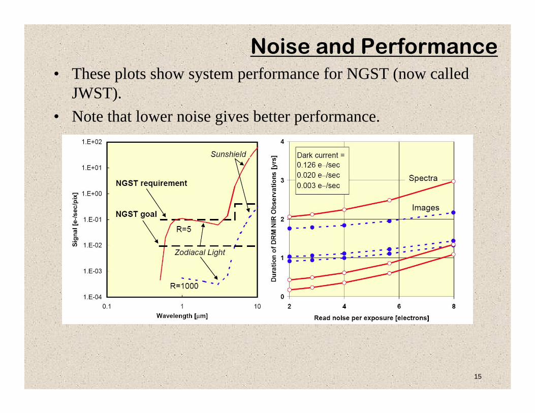
Noise and Performance• These plots show system performance for NGST (now called
JWST).• Note that lower noise gives better performance.
16
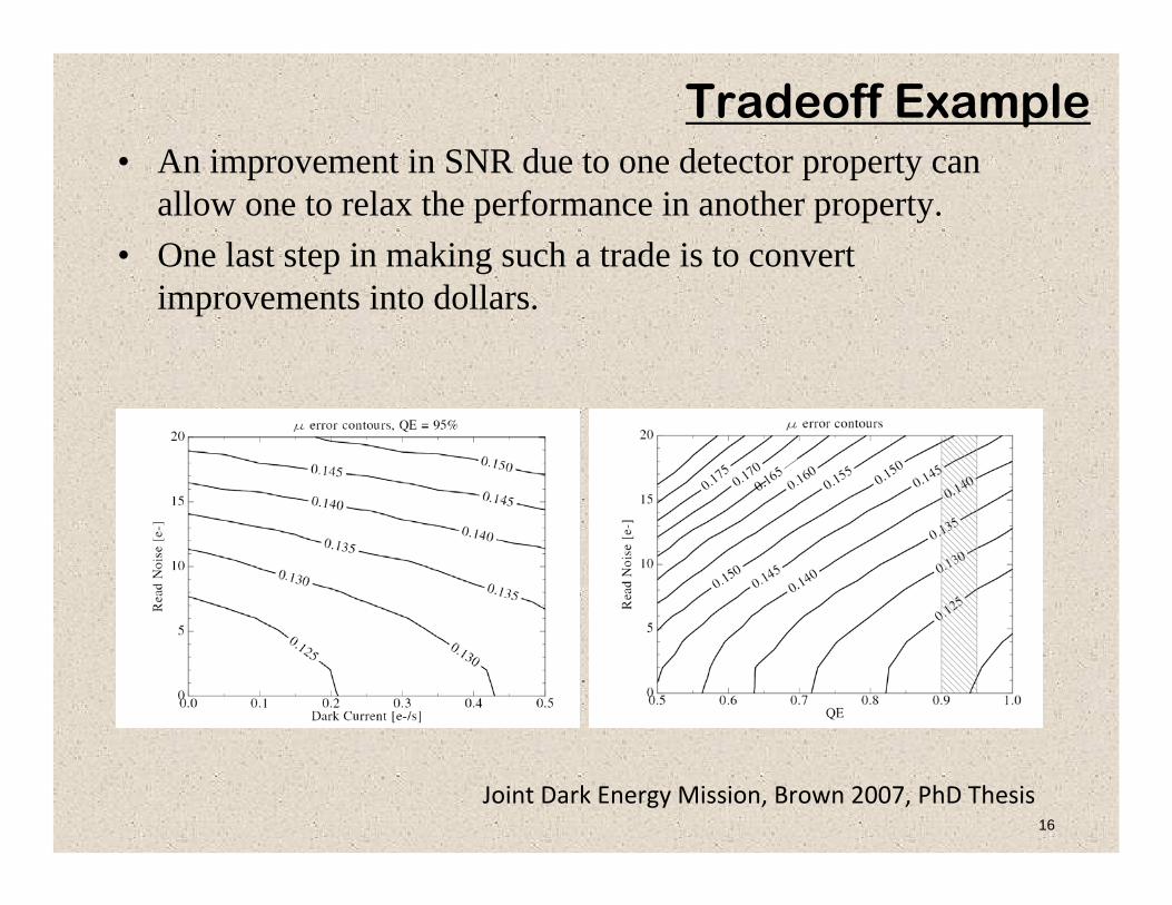
Tradeoff Example• An improvement in SNR due to one detector property can
allow one to relax the performance in another property.• One last step in making such a trade is to convert
improvements into dollars.
Joint Dark Energy Mission, Brown 2007, PhD Thesis

17
Noise Sources: Shot Noise in Signal
18
Shot Noise Described• Photons arrive discretely, independently and randomly and are described
by Poisson statistics. • Poisson statistics tells us that the Root Mean square uncertainty (RMS
noise) in the number of photons per second detected by a pixel is equal to the square root of the mean photon flux (the average number of photons detected per second).
• For example, a star is imaged onto a pixel and it produces on average 10 photo-electrons per second and we observe the star for 1 second, then the uncertainty of our measurement of its brightness will be the square root of 10 i.e. 3.2 electrons. This value is the ‘Photon Noise’. Increasing exposure time to 10 seconds will increase the photon noise to 10 electrons (the square root of 100) but at the same time will increase the ‘Signal to Noise ratio’ (SNR).
• In the absence of other noise sources the SNR will increase as the square root of the exposure time.

19
• The uncertainty in the source charge count is simply the square root of the collected charge.
• Note that if this were the only noise source, then S/N would scale as t1/2. (Also true whenever noise dominated by a steady photon source.)
}.{ −Δ== etQEF
hASN totalsource νν
νη
Photon Shot Noise
20
Noise Sources: Shot Noise from Background

21
• Background photons come from everything but signal from the object of interest!
• Note that the noise contribution is simply the uncertainty in the background level due to shot noise.
}.{,−Δ
== etQEFh
AtCN backtotalbackback νννη&
Noise - sources: Noise from Background
22
Noise Sources: Shot Noise from Dark Current

23
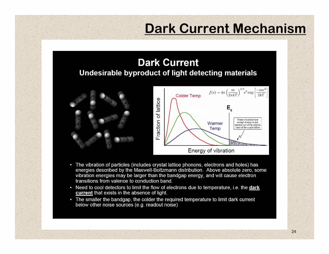
Shot Noise of Dark Current• Charge can also be generated in a pixel either by thermal
motion or by the absorption of photons. • The two cases are indistinguishable. • Dark current can be reduced by cooling.
}.{ −= etCN darkdark&
1
10
100
1000
10000
-110 -100 -90 -80 -70 -60 -50 -40
Temperature Centigrade
Ele
ctro
ns p
er p
ixel
per
hou
r
Dark Current vs. Temperature in Silicon
24
Dark Current Mechanism
25
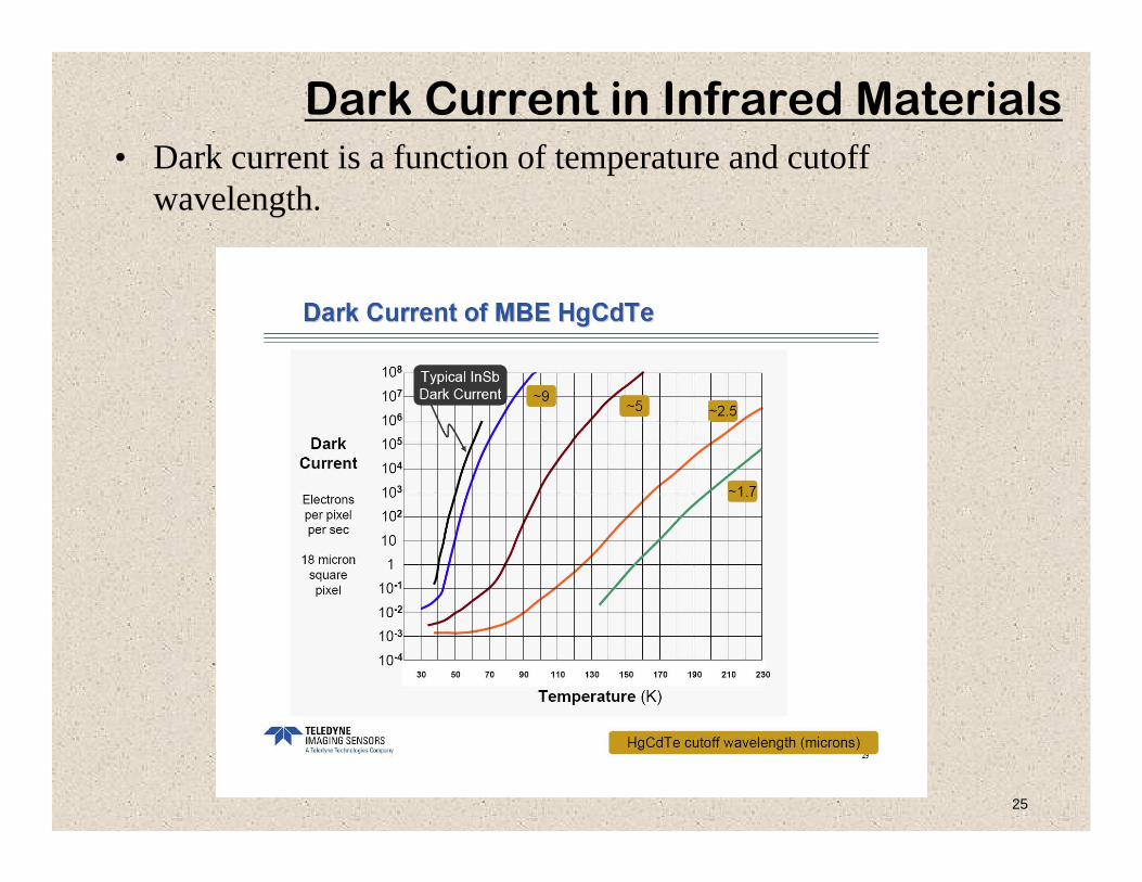
Dark Current in Infrared Materials• Dark current is a function of temperature and cutoff
wavelength.

26
Noise Sources: Thermal Noise
27
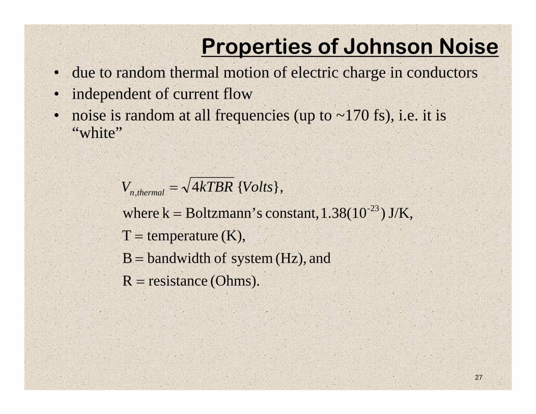
Properties of Johnson Noise• due to random thermal motion of electric charge in conductors• independent of current flow• noise is random at all frequencies (up to ~170 fs), i.e. it is
“white”
(Ohms). resistanceR and (Hz), system ofbandwidth B
(K), etemperaturTJ/K, )1.38(10 constant, sBoltzmann’k where
},{423-
,
===
=
= VoltskTBRV thermaln

28
Bandwidth• The equivalent bandwidth of a circuit is described by the
illustration below.
• In the case of an RC circuit, the bandwidth is given by:
.4
1)2(22
3
RCRCfbandwidthB dB ====
πππ

29
Noise Sources: kTC Noise
30
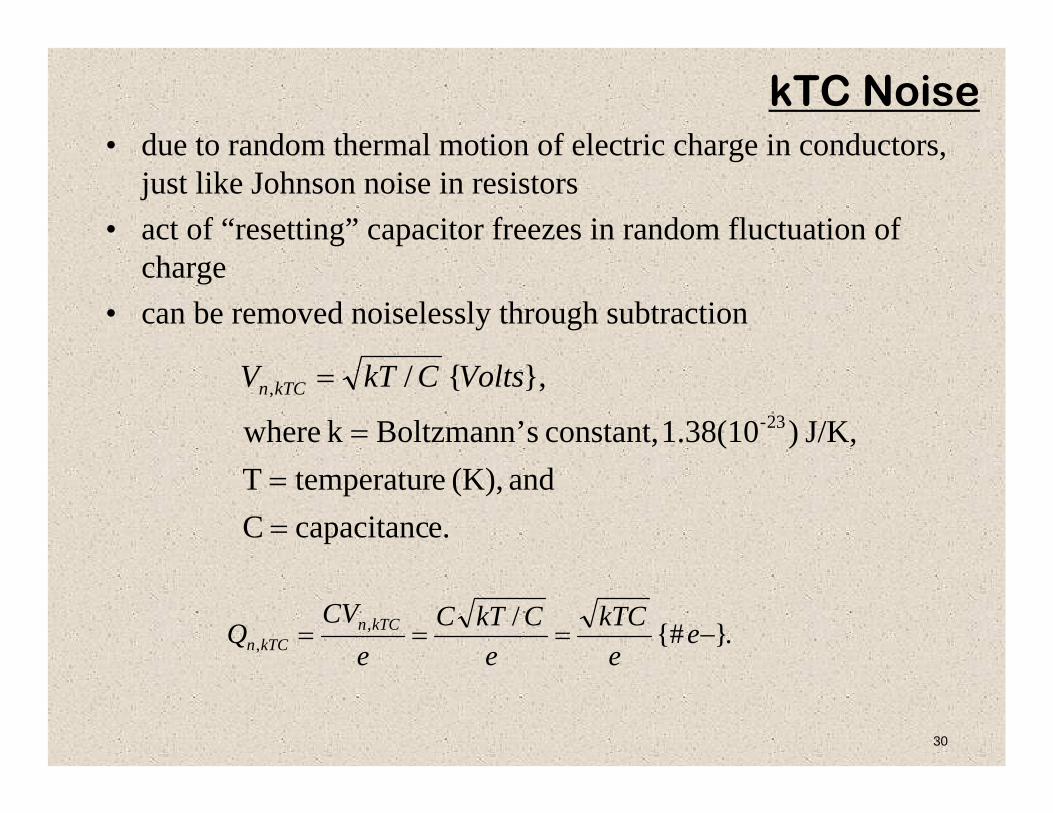
kTC Noise• due to random thermal motion of electric charge in conductors,
just like Johnson noise in resistors• act of “resetting” capacitor freezes in random fluctuation of
charge• can be removed noiselessly through subtraction
e.capacitancCand (K), etemperaturT
J/K, )1.38(10 constant, sBoltzmann’k where
},{/23-
,
==
=
= VoltsCkTV kTCn
.}{#/,, −=== e
ekTC
eCkTC
eCV
Q kTCnkTCn

31
kTC Noise as Reset Noise
32
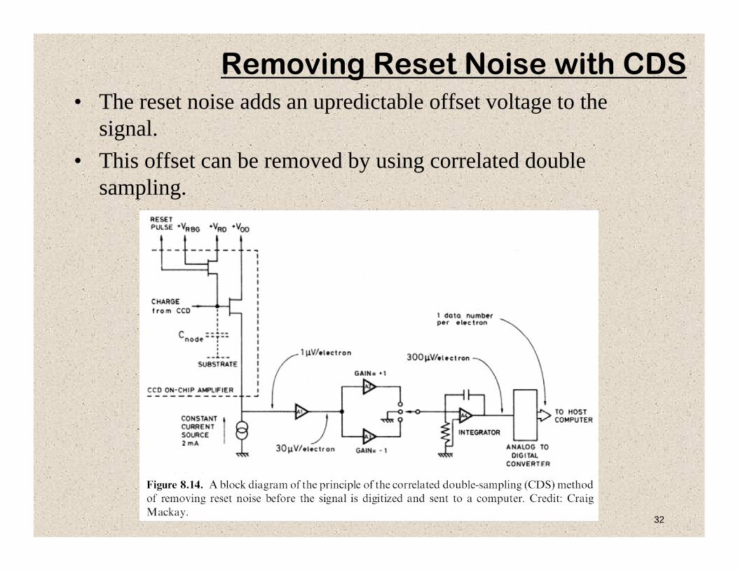
Removing Reset Noise with CDS• The reset noise adds an upredictable offset voltage to the
signal.• This offset can be removed by using correlated double
sampling.

33
Noise Sources: 1/f Noise

34
1/f noise• sometimes called “flicker noise”• caused by traps, often near surface interfaces• occurs in most devices• especially pronounced in FETs with small channels• spectral density increases for lower frequencies
FET. oflength Land FET, ofwidth w
FET, of ecapacitancFET, ofbandwidth
F, V )3(10~ typicallyis
and ogy,on technoldependent strongly is K
},{
224-f
22/1
====Δ
Δ=
ox
ox
ff
Cf
whereVff
wLCK
V
35
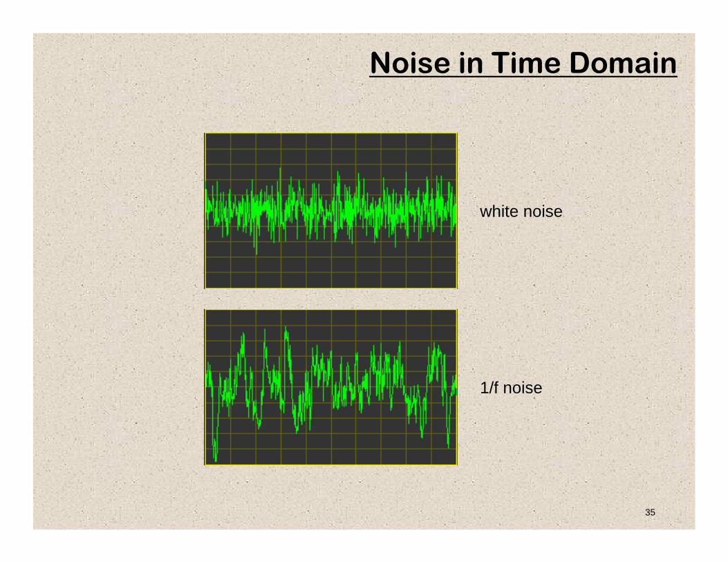
Noise in Time Domain
white noise
1/f noise
36
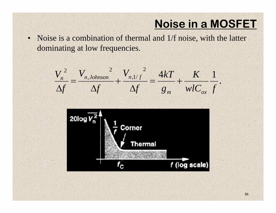
Noise in a MOSFET• Noise is a combination of thermal and 1/f noise, with the latter
dominating at low frequencies.
.142/1,
2,
2
fwlCK
gkT
fV
fV
fV
oxm
fnJohnsonnn +=Δ
+Δ
=Δ
37
Noise Sources: Popcorn Noise

38
Popcorn Noise• This is the minimum noise you can hear in a movie theatre during a tense
scene.• This is noise produced by traps in FET channels that temporarily change
the properties of the channel.• The summation of traps is thought to be a potential source of 1/f noise.

39
Read Noise

40
Read Noise• Read noise is produced by all the electronics in a detector
system, e.g.– Johnson noise, – 1/f noise,– electronic current shot noise, – unstable power supplies
• It is usually measured as the standard deviation in a sample of multiple reads taken with minimum exposure time and under dark conditions.
41
Noise Sources: Electronic Crosstalk

42
signal
Φ1
Φ2
Φ3
ΦR1
ΦR2
ΦR3
Electronic Crosstalk
43
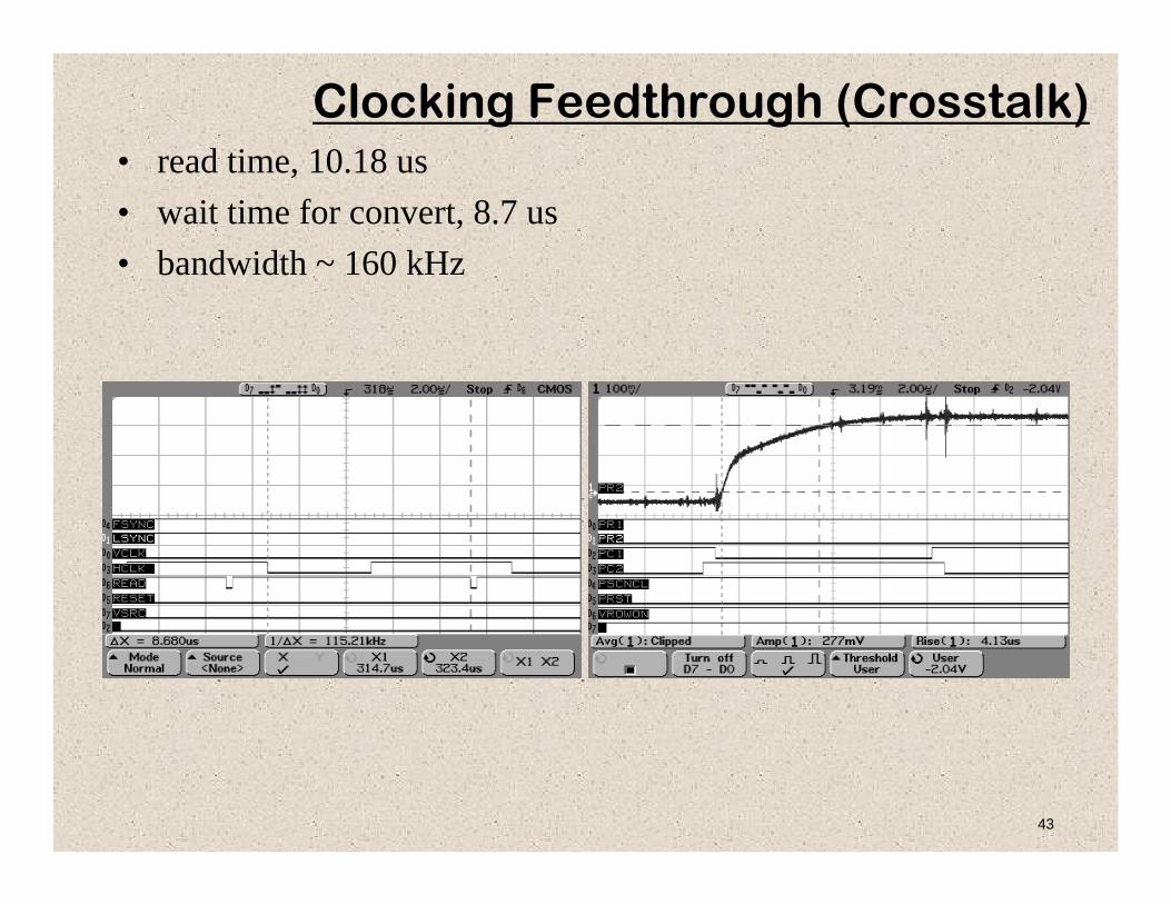
Clocking Feedthrough (Crosstalk)• read time, 10.18 us• wait time for convert, 8.7 us• bandwidth ~ 160 kHz

44
Noise Sources: Pickup or Interference
45
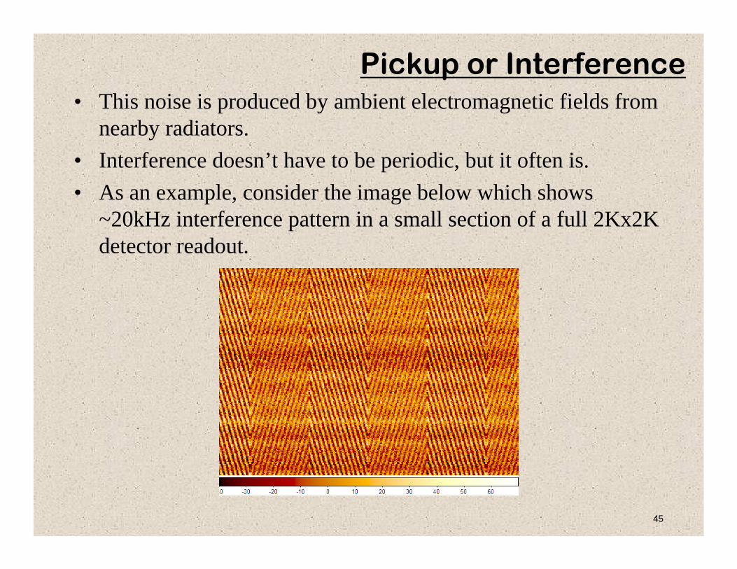
Pickup or Interference• This noise is produced by ambient electromagnetic fields from
nearby radiators. • Interference doesn’t have to be periodic, but it often is.• As an example, consider the image below which shows
~20kHz interference pattern in a small section of a full 2Kx2K detector readout.
46
Improving SNR

47
SNR• SNR can be improved by maximizing the numerator and/or
minimizing the denominator of the full SNR equation.• The choice of what to optimize often comes down to money.
That is, some things are expensive to improve and some are not.
• For instance, the background flux can be reduced in astrophysics applications by launching the system into space (for the cost of billions of dollars….).
.2
, NtitQEFh
AtQEFh
A
tQEFh
A
NSSNR
readdarkbackinstinst
inst
++⎟⎠⎞
⎜⎝⎛ Δ
+⎟⎠⎞
⎜⎝⎛ Δ
Δ
==
νννν
νν
ννη
ννη
ννη

48
Improving SNR• Optical effects
– Throughput: bigger aperture, anti-reflection coatings– Background: low scatter materials, cooling
• Detector effects– Dark current: high purity material, low surface leakage– Read Noise: multiple sampling, in-pixel digitization, photon-counting– QE: thickness optimization, anti-reflection coatings, depleted
• Atmospheric effects– Atmospheric absorption: higher altitude– OH emission: OH suppression instruments– Turbulence: adaptive optics– Ultimate “fix” is to go to space!

49
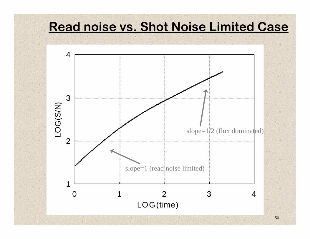
Increasing Integration Time/Coadds• Signal increases with exposure time. Noise can also increase,
but not by as much.• “Coadding” is summing individual exposures – similar to
increasing exposure time.
.
.
.2
,
tN
tQEFh
ASNR
ttQEFh
ASNR
NtitQEFh
AtQEFh
A
tQEFh
A
NSSNR
read
instnoiseread
instnoiseshot
readdarkbackinstinst
inst
∝
Δ
⎯⎯⎯ →⎯
∝Δ
⎯⎯⎯ →⎯
++⎟⎠⎞
⎜⎝⎛ Δ
+⎟⎠⎞
⎜⎝⎛ Δ
Δ
==
νν
νν
νννν
νν
ννη
ννη
ννη
ννη
ννη
50
0 1 2 3 41
2
3
4
LOG(time)
LOG
(S/N
)
slope=1 (read noise limited)
slope=1/2 (flux dominated)
Read noise vs. Shot Noise Limited Case
51
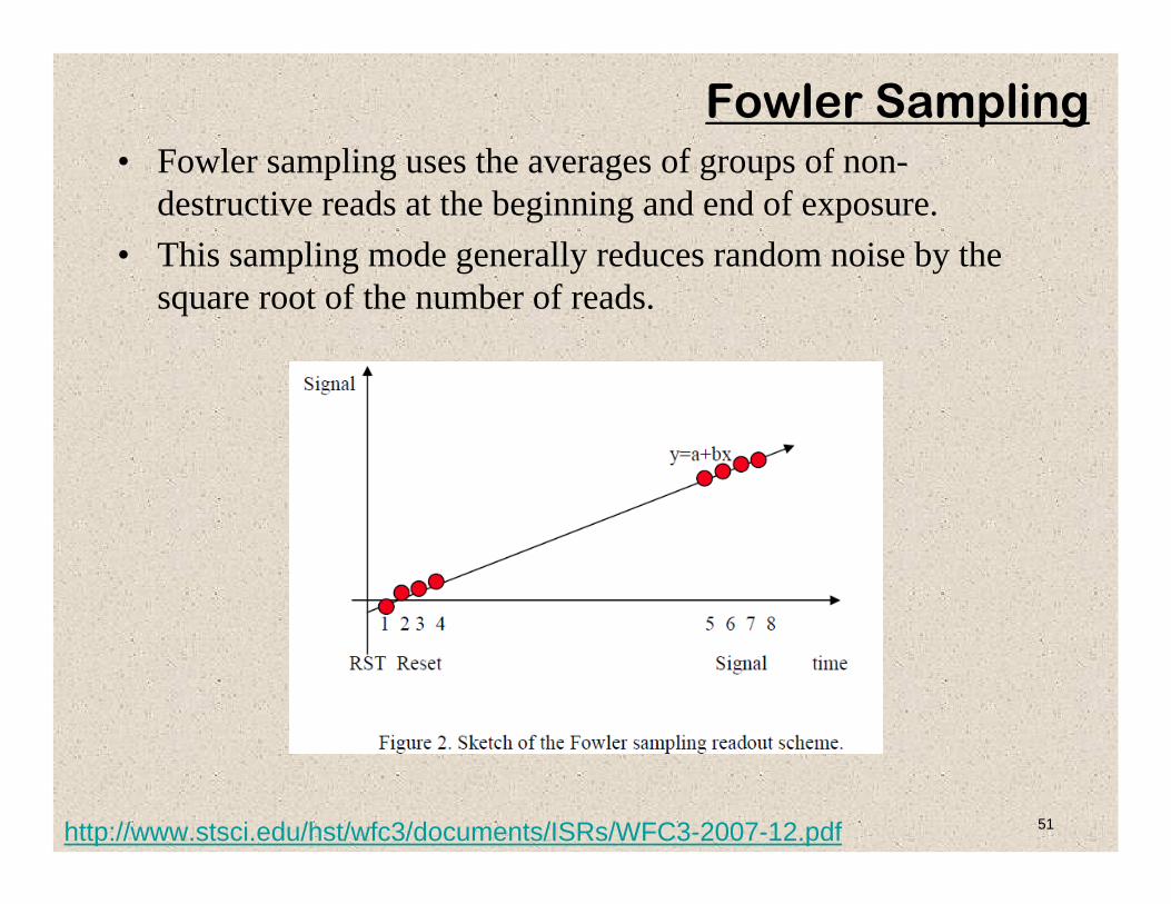
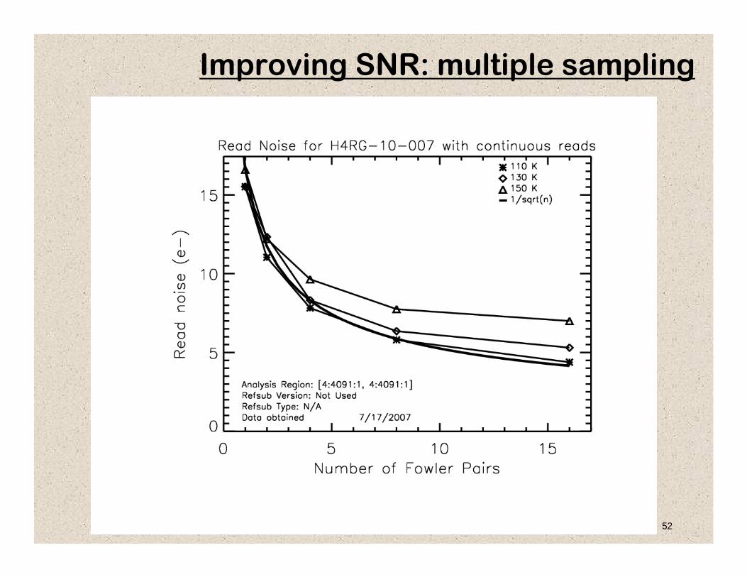
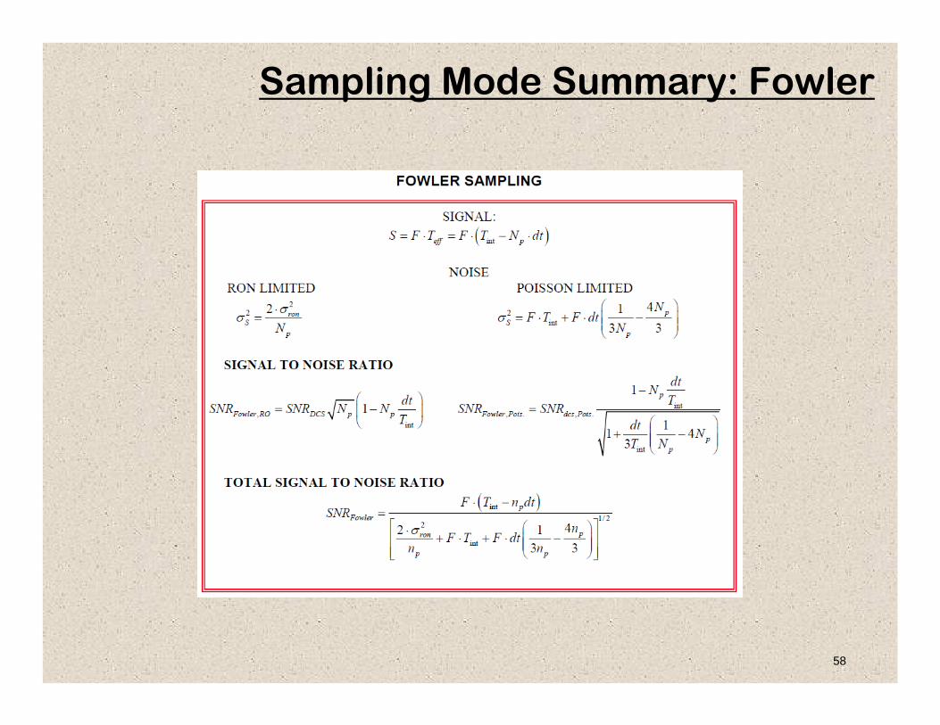
Fowler Sampling• Fowler sampling uses the averages of groups of non-
destructive reads at the beginning and end of exposure.• This sampling mode generally reduces random noise by the
square root of the number of reads.
http://www.stsci.edu/hst/wfc3/documents/ISRs/WFC3-2007-12.pdf
52
Improving SNR: multiple sampling

53
Up-the-ramp Sampling• In up-the-ramp sampling, the signal is non-destructively read
out many times during an exposure.• This read mode generally reduces random noise by the square
root of the number of reads.• The math can be more difficult than for Fowler sampling.• This mode is potentially good for removing cosmic rays.
54
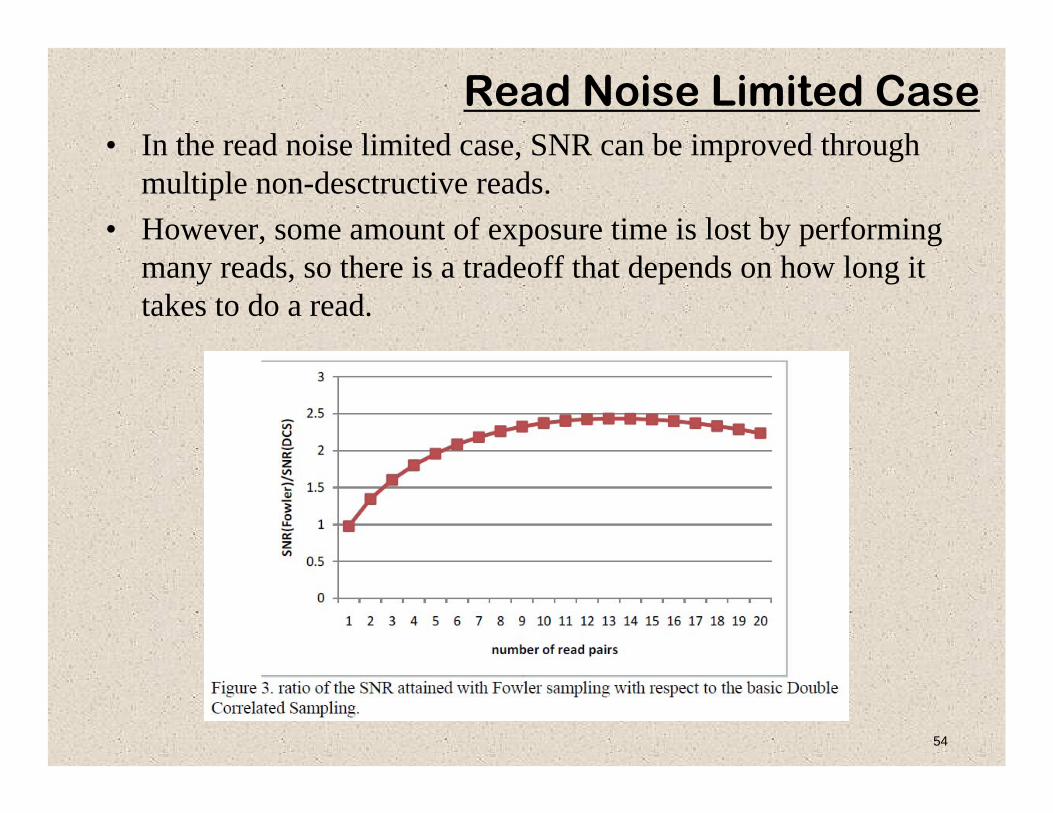
Read Noise Limited Case• In the read noise limited case, SNR can be improved through
multiple non-desctructive reads.• However, some amount of exposure time is lost by performing
many reads, so there is a tradeoff that depends on how long it takes to do a read.
55
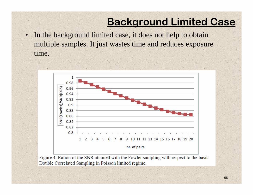
Background Limited Case• In the background limited case, it does not help to obtain
multiple samples. It just wastes time and reduces exposure time.
56
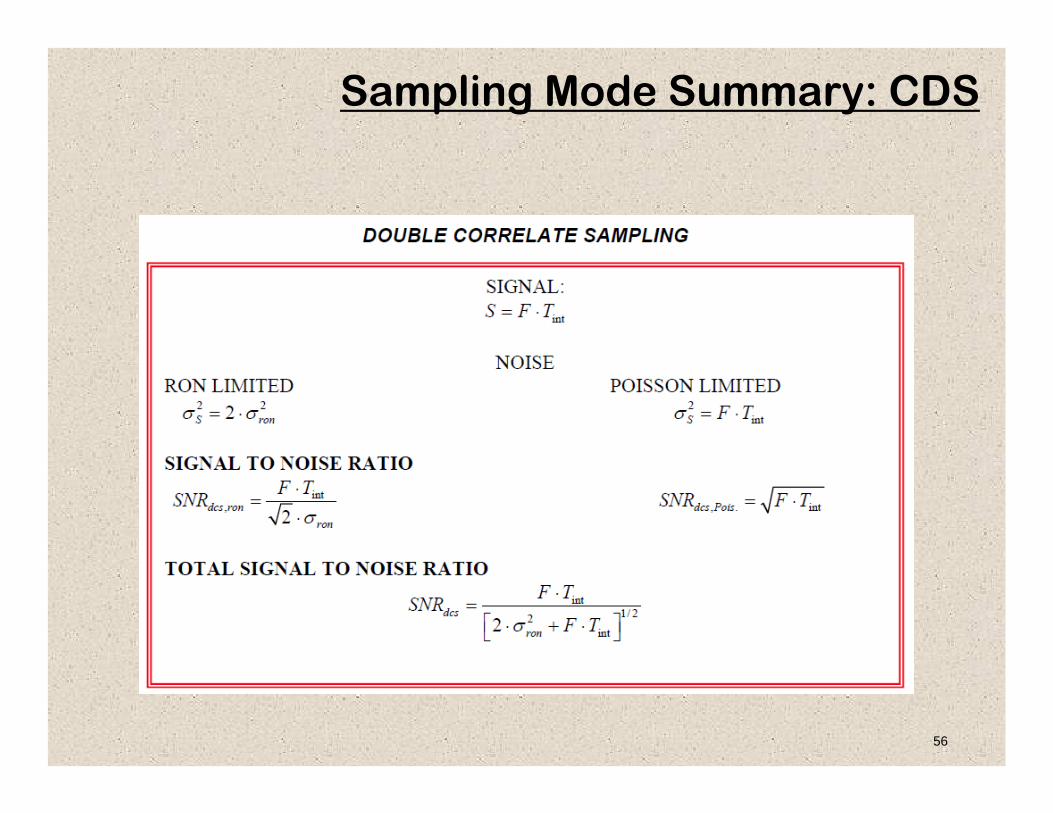
Sampling Mode Summary: CDS

57
Sampling Mode Summary: Up-the-ramp
58
Sampling Mode Summary: Fowler
59
Other Electronic Techniques• bandwidth limiting filters• increasing gain (before noise is injected)• reducing the unit cell capacitance (thereby increasing in-pixel
gain).


![INDEX [ridl.cfd.rit.edu]ridl.cfd.rit.edu/products/manuals/Sunix/IO/PCI IO/Manual/Parallel.pdf · INDEX WHQL Certification ... ¾ 4.2 Driver Installation Guide (Windows 2000) ... Please](https://static.fdocuments.in/doc/165x107/5adc6a4c7f8b9a595f8b80e4/index-ridlcfdriteduridlcfdriteduproductsmanualssunixiopci-iomanual.jpg)


