Detection of MICR Number and Verification of WaterMark in ... V.pdf · Detection of MICR Number and...
13
1 Detection of MICR Number and Verification of WaterMark in a Cheque Karthik V July 9, 2015
-
Upload
dinhnguyet -
Category
Documents
-
view
225 -
download
0
Transcript of Detection of MICR Number and Verification of WaterMark in ... V.pdf · Detection of MICR Number and...
1
Detection of MICR Number and Verification of WaterMark in a Cheque
Karthik V
July 9, 2015
2
Certificate
This is to certify that Mr. V.Karthik, pursuing Dual Degree course at Indian Institute of
Technology, Kharagpur in Electrical Engineering has undertaken a project as a summer intern at
IDRBT, Hyderabad from April 2015 to July 2015.
He was assigned the project “Detection of Frauds in Cheque Truncation System” under
my guidance. The project reports submitted to Institute for Development and Research in Banking
Technology [IDRBT], Hyderabad is a bonafide work done by V.Karthik. During the course of the
project he has undertaken a study of Digital Image Processing and worked on various image
processing techniques which are used to extract several important features of a cheque. He has
also carried out an excellent work in his respective fields. I wish him all the best for all his
endeavors.
Dr. Rajarshi Pal
(Project Guide)
Assistant Professor
IDRBT, Hyderabad
3
Acknowledgment
I would like to express my sincere gratitude to the Institute for Development and Research in
Banking Technology (IDRBT) and particularly Dr. Rajarshi Pal who was my guide for this project.
This opportunity of learning about Digital Image Processing was a boon to me as one rarely gets
such exposure. I would like to add that this short period in IDRBT has added a different facet to
my life as this is a unique organization being a combination of academics, research, technology,
communication services, crucial applications, etc.
I am extremely grateful to Dr. Rajarshi Pal for his advice, innovative suggestions and
supervision. I thank him for introducing me to this excellent area of Digital Image Processing. I
am thankful to IDRBT for providing such an amazing platform for students, like me, to work in
real application oriented research. I thank one and all who made this project successful either
directly or indirectly.
Lastly, I thank Pramod Kumar and Prabhat Dansena for providing continuous support and
guidance during this period.
V.Karthik
IIT Kharagpur
4
Introduction
Cheque Truncation System (CTS) is the process to overcome the flow of the physical cheque
issued by a drawer at some point by the presenting bank en-route to the drawee bank branch. In its
place an electronic image of the cheque is transmitted to the drawee branch through the clearing
house, along with relevant information like data on the Magnetic Ink Coded Recognition (MICR)
band, date of presentation, presenting bank, etc.
It speeds up the process of clearing of cheques resulting in better service to customers,
reduces the scope for clearing-related frauds or loss of instruments in transit, lowers the cost of
collection of cheques, and removes reconciliation-related and logistics-related problems, thus
benefiting the system as a whole. With the other major products being offered in the form of Real-
time gross settlement systems(RTGS) and National Electronic Funds Transfer(NEFT), the Reserve
Bank of India has created the capability to enable inter-bank and customer payments on-line and
in near-real time. However, as cheques are still the prominent modes of payments in the country.
Reserve Bank of India has therefore, decided to focus on improving the efficiency of the cheque
clearing cycle, offering Cheque Truncation System (CTS) as an alternative.
Features in CTS 2010
In CTS, the presenting bank (or its branch) captures the data and the images of a cheque using
their scanner System. A cheque according to “CTS-2010” and have to meet the following
specifications and standards prescribed by Reserve Bank of India as shown in Fig.1.
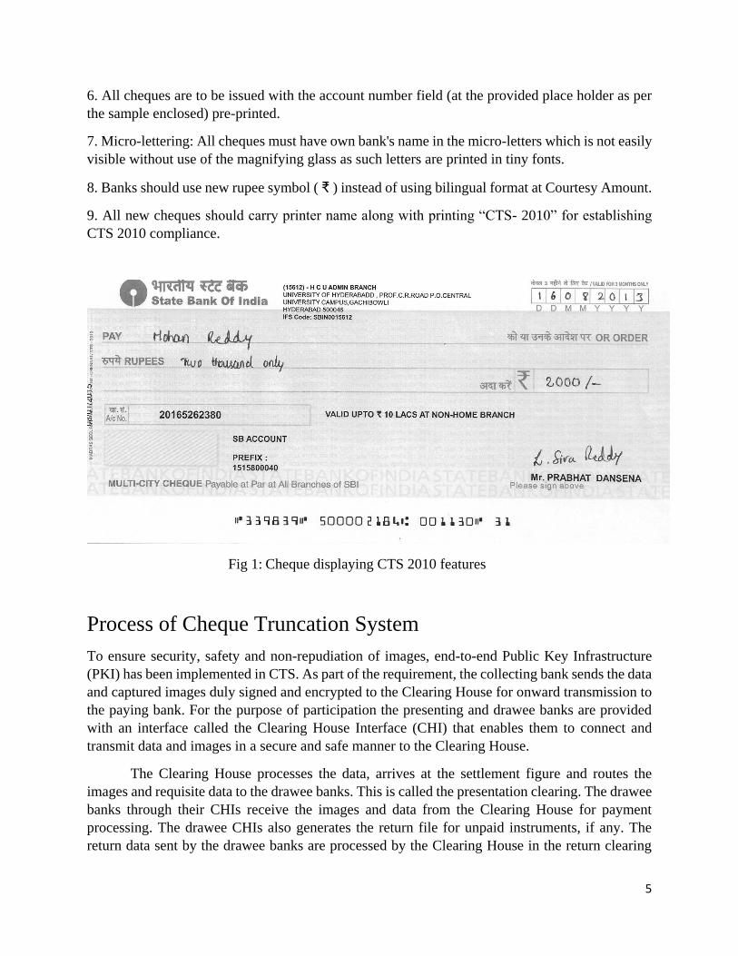
1. Watermark of CTS 2010 with bigger diameter as 3.0 centimeters and smaller diameter as 2.6
centimeters. Each cheque needs to hold at least one full water mark
2. Void Pantograph-“VOID” that are intended to appear on copies as a security measure to prevent
duplication must not be visible on either gray scale or black and white images capture from original
cheques under CTS clearing environment
3. Ultra Violet (UV) logo of the bank should be printed at upper left hand corner of the cheque (At
place specified in sample cheque) along with or without bank name details in ultra-violet (UV)
ink. The logo will visible in UV- lamps to establish the genuineness of the cheque.
4. Significant fields of a cheque such as Date, Payee Name, Legal and Courtesy Amount, Drawee
Account No., Drawee Signature space etc. have been standardized.
5. All cheques are required to be printed in light pastel colors. Banks should take care while
selecting cheques printing color that Print Contrast Ratio/ Dynamic Contrast Ratio should not
exceed 60 under Cheque Truncation System (CTS) clearing.
5
6. All cheques are to be issued with the account number field (at the provided place holder as per
the sample enclosed) pre-printed.
7. Micro-lettering: All cheques must have own bank's name in the micro-letters which is not easily
visible without use of the magnifying glass as such letters are printed in tiny fonts.
8. Banks should use new rupee symbol ( ₹ ) instead of using bilingual format at Courtesy Amount.
9. All new cheques should carry printer name along with printing “CTS- 2010” for establishing
CTS 2010 compliance.
Fig 1: Cheque displaying CTS 2010 features
Process of Cheque Truncation System
To ensure security, safety and non-repudiation of images, end-to-end Public Key Infrastructure
(PKI) has been implemented in CTS. As part of the requirement, the collecting bank sends the data
and captured images duly signed and encrypted to the Clearing House for onward transmission to
the paying bank. For the purpose of participation the presenting and drawee banks are provided
with an interface called the Clearing House Interface (CHI) that enables them to connect and
transmit data and images in a secure and safe manner to the Clearing House.
The Clearing House processes the data, arrives at the settlement figure and routes the
images and requisite data to the drawee banks. This is called the presentation clearing. The drawee
banks through their CHIs receive the images and data from the Clearing House for payment
processing. The drawee CHIs also generates the return file for unpaid instruments, if any. The
return data sent by the drawee banks are processed by the Clearing House in the return clearing
6
session in the same way as presentation clearing and return data is provided to the presenting banks
for processing. The clearing cycle is treated as complete once the presentation clearing and the
associated return clearing sessions are successfully processed. The entire essence of CTS
technology lies in the use of images of cheques instead of the physical cheques for payment
processing.
Benefits of Cheque Truncation System
The benefits are many. With the introduction of imaging and truncation, the physical movement
of instruments is stopped. The electronic movement of images can facilitate reduction in the
clearing cycles as well. Moreover, there is no fear of loss of instruments in transit. Further,
limitations of the existing clearing system in terms of geography or jurisdiction can be removed,
thus enabling consolidation and integration of multiple clearing locations managed by different
banks with varying service levels into a nation-wide standard clearing system with uniform
processes and practices.
CTS also benefits issuers of cheques. Use of images removes the need to handle and move
physical cheques at different points. The scope for frauds inherent in paper instruments is, thus,
greatly reduced. The Corporates if needed can be provided with images of cheques by their bankers
for internal requirements, if any. As only the images move, the time taken for receipt of paid
cheques is reduced which also gives an early opportunity to the issuers of cheques to detect frauds
or alterations.
CTS brings elegance to the entire activity of cheque processing and clearing. Cheque frauds
can be greatly reduced with introduction of common minimum security features prescribed under
CTS Standards 2010 for early interception of altered or forged instruments. Eliminating the need
to move the physical cheques is extremely beneficial in terms of cost and time savings.
The benefits from CTS could be summarized as follows
Shorter clearing cycle.
Superior verification and reconciliation process.
No geographical restrictions as to jurisdiction.
Operational efficiency for banks and customers alike.
Reduction in operational risk and risks associated with paper clearing.
Objective A bank’s logo is used as watermark which is visible when held slightly across light. It plays a
crucial role in verifying the originality of the cheque as a copied duplicate cheque cannot replicate
a watermark.
Detecting these watermarks from cheque images and verification of them proves the
originality of the cheque. This is the objective of the current project.
7
Extraction of MICR Code
Each bank use its own watermark. Hence, detecting the issuer bank the first step of extraction and
verification of this watermark. The issuer bank can be identified from the MICR code of a cheque.
Magnetic Ink Character Recognition (MICR) code is a character-recognition technology
used mainly by the banking industry to ease the processing and clearance of cheques and other
documents. Each cheque has a unique MICR number. The MICR encoding, called the MICR line,
is at the bottom of cheques and typically includes the document-type indicator, bank code, bank
account number, cheque number, cheque amount, and a control indicator.
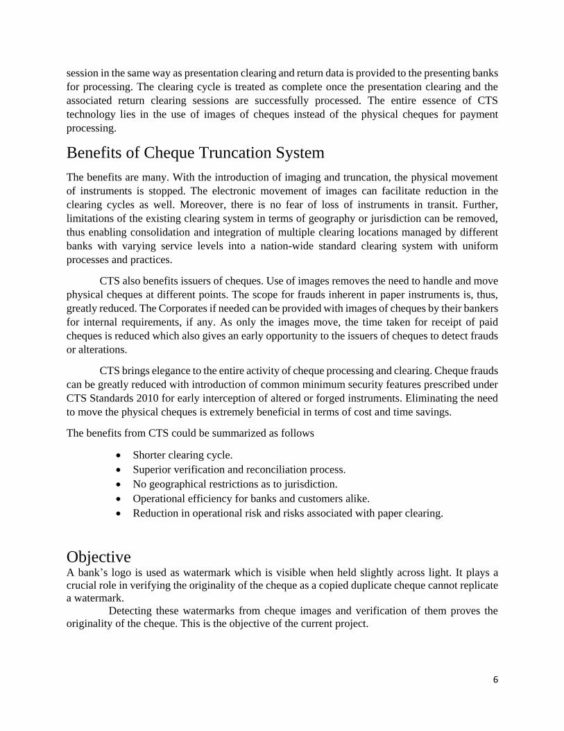
Prior knowledge about the placement of Magnetic Ink Character Recognition (MICR) line
region in cheque is used here. It can be observed from Fig. 2 that the MICR line is printed at the
bottom of the image that the MICR line is printed at the bottom of the image.
Fig 2: MICR Region
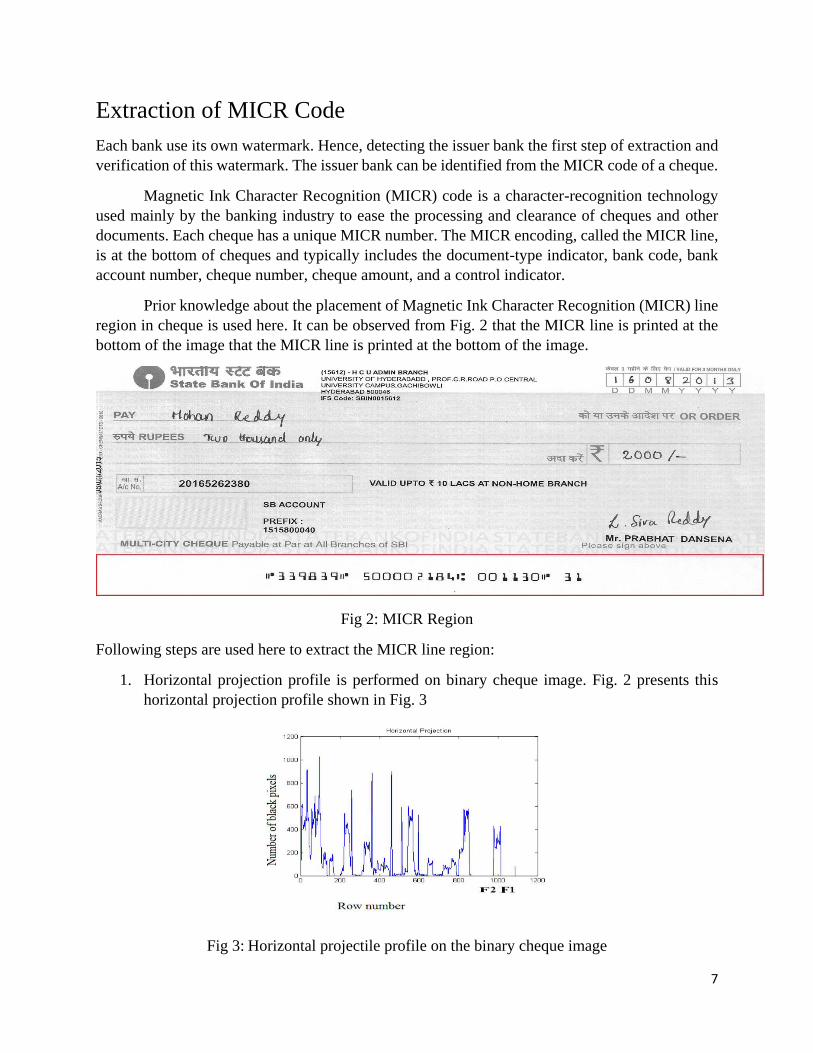
Following steps are used here to extract the MICR line region:
1. Horizontal projection profile is performed on binary cheque image. Fig. 2 presents this
horizontal projection profile shown in Fig. 3
Fig 3: Horizontal projectile profile on the binary cheque image
8
2. As the MICR line is located at the bottom of the cheque, the upper most and the lowest row
containing the MICR region is determined by observing the first sudden rise (at row F1), followed
by a series of high values, and a sudden drop (at row F2) of HPP values while examining the HPP
values from the right side (as shown in Fig 3). Then these series of contiguous rows are cropped
from the binary image.
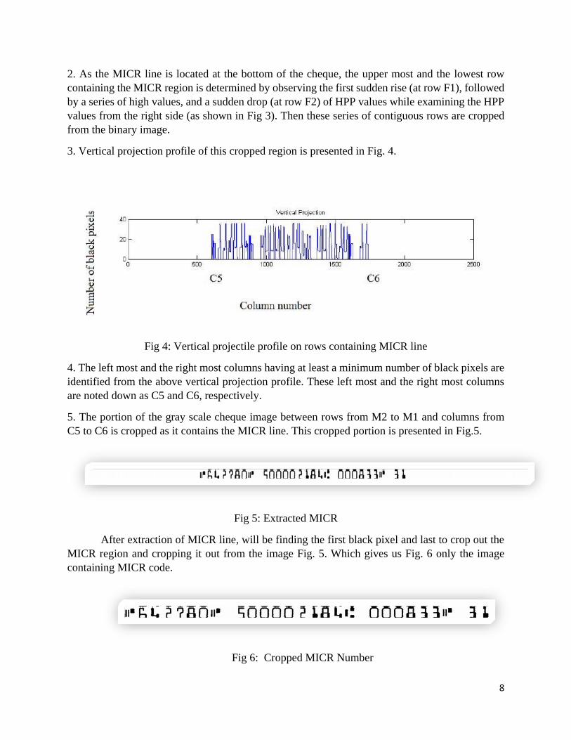
3. Vertical projection profile of this cropped region is presented in Fig. 4.
Fig 4: Vertical projectile profile on rows containing MICR line
4. The left most and the right most columns having at least a minimum number of black pixels are
identified from the above vertical projection profile. These left most and the right most columns
are noted down as C5 and C6, respectively.
5. The portion of the gray scale cheque image between rows from M2 to M1 and columns from
C5 to C6 is cropped as it contains the MICR line. This cropped portion is presented in Fig.5.
Fig 5: Extracted MICR
After extraction of MICR line, will be finding the first black pixel and last to crop out the
MICR region and cropping it out from the image Fig. 5. Which gives us Fig. 6 only the image
containing MICR code.
Fig 6: Cropped MICR Number
9
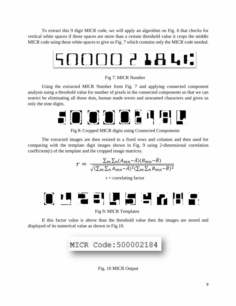
To extract this 9 digit MICR code, we will apply an algorithm on Fig. 6 that checks for
vertical white spaces if those spaces are more than a certain threshold value it crops the middle
MICR code using these white spaces to give us Fig. 7 which contains only the MICR code needed.
Fig 7: MICR Number
Using the extracted MICR Number from Fig. 7 and applying connected component
analysis using a threshold value for number of pixels in the connected components so that we can
restrict be eliminating all those dots, human made errors and unwanted characters and gives us
only the nine digits.
Fig 8: Cropped MICR digits using Connected Components
The extracted images are then resized to a fixed rows and columns and then used for
comparing with the template digit images shown in Fig. 9 using 2-dimensional correlation
coefficient(r) of the template and the cropped image matrices.
𝑟 = ∑ ∑ (𝐴𝑚𝑛−�̅�)(𝐵𝑚𝑛−�̅�)𝑛𝑚
√(∑ ∑ 𝐴𝑚𝑛−�̅�𝑛𝑚 )2(∑ ∑ 𝐵𝑚𝑛−�̅�𝑛𝑚 )2
r = correlating factor
Fig 9: MICR Templates
If this factor value is above than the threshold value then the images are stored and
displayed of its numerical value as shown in Fig.10.
Fig. 10 MICR Output
10
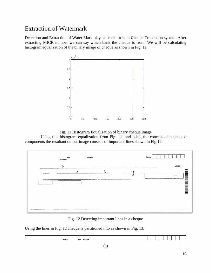
Extraction of Watermark
Detection and Extraction of Water Mark plays a crucial role in Cheque Truncation system. After
extracting MICR number we can say which bank the cheque is from. We will be calculating
histogram equalization of the binary image of cheque as shown in Fig. 11
Fig. 11 Histogram Equalization of binary cheque image
Using this histogram equalization from Fig. 11. and using the concept of connected
components the resultant output image consists of important lines shown in Fig 12.
Fig. 12 Detecting important lines in a cheque
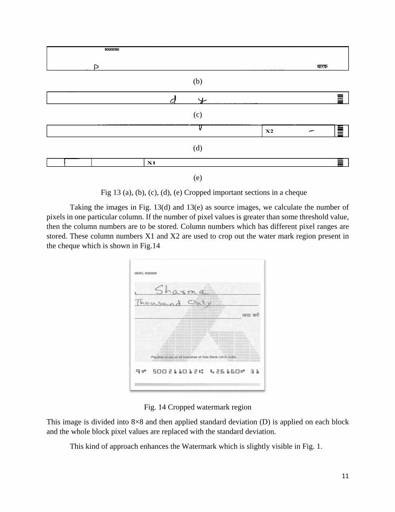
Using the lines in Fig. 12 cheque is partitioned into as shown in Fig. 13.
(a)
11
(b)
(c)
(d)
(e)
Fig 13 (a), (b), (c), (d), (e) Cropped important sections in a cheque
Taking the images in Fig. 13(d) and 13(e) as source images, we calculate the number of
pixels in one particular column. If the number of pixel values is greater than some threshold value,
then the column numbers are to be stored. Column numbers which has different pixel ranges are
stored. These column numbers X1 and X2 are used to crop out the water mark region present in
the cheque which is shown in Fig.14
Fig. 14 Cropped watermark region
This image is divided into 8×8 and then applied standard deviation (D) is applied on each block
and the whole block pixel values are replaced with the standard deviation.
This kind of approach enhances the Watermark which is slightly visible in Fig. 1.
12
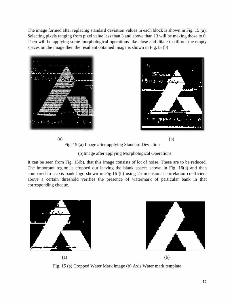
The image formed after replacing standard deviation values in each block is shown in Fig. 15 (a).
Selecting pixels ranging from pixel value less than 3 and above than 13 will be making those to 0.
Then will be applying some morphological operations like close and dilate to fill out the empty
spaces on the image then the resultant obtained image is shown in Fig.15 (b)
(a) (b)
Fig. 15 (a) Image after applying Standard Deviation
(b)Image after applying Morphological Operations
It can be seen from Fig. 15(b), that this image consists of lot of noise. These are to be reduced.
The important region is cropped out leaving the blank spaces shown in Fig. 16(a) and then
compared to a axis bank logo shown in Fig.16 (b) using 2-dimensional correlation coefficient
above a certain threshold verifies the presence of watermark of particular bank in that
corresponding cheque.
(a) (b)
Fig. 15 (a) Cropped Water Mark image (b) Axis Water mark template
13
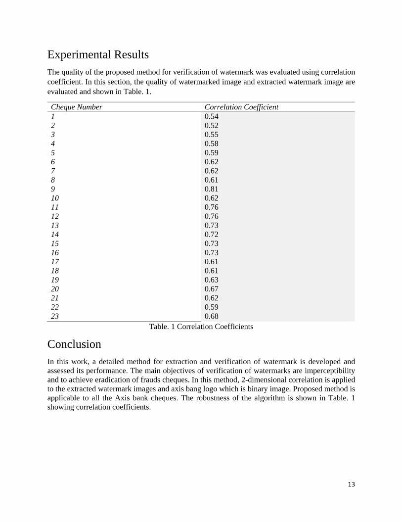
Experimental Results
The quality of the proposed method for verification of watermark was evaluated using correlation
coefficient. In this section, the quality of watermarked image and extracted watermark image are
evaluated and shown in Table. 1.
Cheque Number Correlation Coefficient
1
2
3
4
5
6
7
8
9
10
11
12
13
14
15
16
17
18
19
20
21
22
23
0.54
0.52
0.55
0.58
0.59
0.62
0.62
0.61
0.81
0.62
0.76
0.76
0.73
0.72
0.73
0.73
0.61
0.61
0.63
0.67
0.62
0.59
0.68
Table. 1 Correlation Coefficients
Conclusion
In this work, a detailed method for extraction and verification of watermark is developed and
assessed its performance. The main objectives of verification of watermarks are imperceptibility
and to achieve eradication of frauds cheques. In this method, 2-dimensional correlation is applied
to the extracted watermark images and axis bang logo which is binary image. Proposed method is
applicable to all the Axis bank cheques. The robustness of the algorithm is shown in Table. 1
showing correlation coefficients.