Detection of Landmines and Explosives Using...
12
Seminar Ib Detection of Landmines and Explosives Using Neutrons Author: Matija Kregar Advisor: izr. prof. dr. Samo Korpar Ljubljana, May 2016 Abstract The task of humanitarian demining is in great need of technological improvement. The neutron based elemental analysis is somewhat helpful in this regard. Being a method that is based on identifying actual explosive material it is predominantly used for landmine confirmation after traditional methods locate the suspect area. In cargo / baggage inspection neutron based methods show more promising results. This paper will focus on the most common detection methods using neutron irradiation and describe a few detectors in testing and practical use.
Transcript of Detection of Landmines and Explosives Using...

Seminar Ib
Detection of Landmines and Explosives Using Neutrons
Author: Matija Kregar Advisor: izr. prof. dr. Samo Korpar
Ljubljana, May 2016
Abstract
The task of humanitarian demining is in great need of technological improvement. The neutron based elemental analysis is somewhat helpful in this regard. Being a method that is based on identifying actual explosive material it is predominantly used for landmine confirmation after traditional methods locate the suspect area. In cargo / baggage inspection neutron based methods show more promising results. This paper will focus on the most common detection methods using neutron irradiation and describe a few detectors in testing and practical use.

1. Introduction 2. Neutron Sources
2.1 Californium 252 2.2. Neutron Generators
3. Detection Methods 3.1. Neutron Induced Gamma Emission
3.1.1 Thermal Neutron Analysis (TNA) 3.1.2. Fast Neutron Analysis (FNA) 3.1.3. Associated Particle Technique 3.1.4. Pulsed FastThermal Neutron Analysis, PELAN Detector
3.2. Neutron Moderation and Backscattering 3.2.1. ESCALAD Detector
4. Conclusion 5. References
1. Introduction Buried and forgotten landmines present a permanent humanitarian threat. It is estimated that
there are over 110 million landmines scattered in over 70 affected countries in different regions of the world [1.]. Humanitarian demining is a time consuming and tedious process, since cleaning an area means removing all threats and not only finding a safe passage as is usually the case with demining for military purposes. Using traditional methods such as metal detectors, prodding and dogs without any improvement in technology, centuries of demining will be required. Older landmines contain significant metal parts, but modern landmines are mostly made of plastic with minimal metal content which makes them harder to detect with standard metal detectors. Since most of the landmines are buried close to battle zones riddled with metal debris, increasing the metal detector sensitivity drastically increases the amount of false positive detections and further increasing the difficulty of the process. Fortunately, to battle these problems, more and more resources have been allocated for development of more efficient methods such as ground penetrating radar [2.], Xray imaging [1.], nuclear quadrupole resonance [3.], infrared scanners [4.], neutron irradiation [1.], etc.. Some are in more advanced stages, while some are in early development.
Neutrons are one of the few methods available for elemental analysis of hidden objects. They are suitable for exploring large volumes due to their ability to penetrate thick layers of material and interact with inspected objects. Detection techniques rely on the fact that the explosives contain hydrogen, carbon, nitrogen and oxygen in various ratios. Some most common explosives are: TNT C7H5N3O6, RDX C3H6N6O6, pentrite O12N4C5H8, hexogen O8N8C4H8, ammonium nitrite O3N2H4. This means that the problem of explosive identification is reduced to the problem of identification of light elements [1.].
This paper will focus on most common detection methods using neutron irradiation and describe a few detectors in testing and practical use.
2. Neutron Sources Neutron sources for neutron interrogation can either be radioactive sources (252Cf, AmBe) or
particle accelerators or compact electronic neutron generators. Some of more frequently used sources used in explosives detector applications will be discussed in more detail.
1

2.1 Californium 252
252Cf is an isotropic spontaneous fission neutron source. Its predominant decay is α emission with half life of 2.592 years. Half life for spontaneous fission is about 85 years. It is produced by neutron irradiation of curium isotopes 244 to 248 [5.]. Fission neutrons have an energy range of 0 to 13 MeV with a mean value of 2.3 MeV and a most probable value of 1 MeV [5.]. It’s output is ~2.34 × 10⁶ neutrons/s per microgram [6.].
252Cf is an economical neutron source, sufficient in small quantities which makes it highly portable. Its downside is that it is dangerous, cannot be turned off when not in operation and poses a threat of radioactive contamination. The required shielding can in many cases greatly exceed the size of the source itself.
2.2. Neutron Generators
Electronic neutron generators produce neutrons by colliding accelerated deuterons into light tritium or deuterium nuclei. The deuterontriton fusion reaction D + T→ n +4He produces neutrons with the energy of En = 14.1 MeV and the deuterondeuteron reaction D + D → n + 3He generates neutrons with the energy of En = 2.5 MeV [7.]. In both cases the associated He nuclei exit in the opposite direction to the one of the neutron to conserve the system’s momentum. The neutron output for electronic neutron generators is typically in the range of 106 1011 neutrons/s. Generators can usually be operated in continuous or pulsed mode and can of course be turned off when not in operation.
Sealed neutron tubes are the most common form of a neutron generator used in landmine and explosives detectors. The ion source, ion optic elements and a beam target are enclosed in a vacuum tight enclosure embedded in a metal housing. The acceleration section is typically housed in a ceramic envelope to provide high voltage insulation. They use an external power supply and are mobile, durable and reliable [7.]. To illustrate the physical properties of sealed neutron tubes let us look at a prototype compact neutron generator developed in University of California, Berkeley [8.]. It uses a radio frequency ion source where 13.65 MHz electromagnetic fields (100W 150W) energize cold electrons to form the ion source plasma. To achieve a neutron yield of 107 to 108 n/s with the DT reaction, an ion current of 20μA to 80μA at an acceleration voltage of 80 kV is required. It’s housing is a stainless steel vacuum cross that measures about 27 cm in both directions.
3. Detection Methods In the process of neutron irradiation the neutrons are either captured or scattered. In
scattering the neutron collides with the nucleus which either remains in its ground state but with additional kinetic energy from the neutron (elastic scattering) or is activated in a short lived excited state (inelastic scattering) and usually returns to the ground state by emitting a γ ray. Whether the scattering is elastic or inelastic is determined by the energy of the neutron, the nucleus and its neutron cross section [9.]. When a neutron is captured by the nucleus, the new nucleus is usually left in an excited state. It returns to a stable state by emitting one or more γ rays or other particles. The energy of emitted γ rays are characteristic of the target nucleus.
3.1. Neutron Induced Gamma Emission
Neutrons from the source penetrate the ground and cause γ ray emission through inelastic scattering or capture. Systems that employ these methods use neutron sources and γ detectors to determine the composition of the scanned material or a presence of certain elements.
2

3.1.1 Thermal Neutron Analysis (TNA)
Thermal neutron analysis focuses on detecting anomalies of nitrogen concentrations in inspected material. The thermal neutron capture cross section for nitrogen is considerably higher than the ones of other elements usually present in explosives (Table 1). Nitrogen is present in high concentrations (1738%) in known explosives and significantly less (under 0.1%) even in heavily fertilized soil [10.]. Neutrons from the source are moderated (thermalized) to energies of approximately 0.025 eV [11.] and used to irradiate the scanned area. Thermal neutrons are captured by the nitrogen nucleus and a capture γ ray with the energy of 10.83 MeV is emitted (Fig. 3.1) with 18% probability. This energy is higher than the energy of γ rays induced by neutron irradiation of common material and can thus be easily identified in the energy spectrum.252Cf is usually used as the source of the neutrons since the energy spectrum of the emitted neutrons is more suitable for moderation. It is also commercially available and economical.
Element σ [mb]
H 332
C 3.5
O 0.19
N 1910
Table 1: Thermal neutron capture cross section [12.]
Fig. 3.1: Thermal neutron analysis reaction diagram [13.].
A TNA detector (Fig. 3.2) is used as a confirmation tool for a multi detector setup mounted on
a vehicle called Improved Landmine Detection System (ILDS) developed for the Canadian Army for rear area landmine clearance in combat situations and peacekeeping on roads and tracks. It uses an electromagnetic induction metal detector, infrared imaging and ground probing radar as scanning technologies that detect properties associated with mines while the vehicle moves and a TNA detector to confirm the presence of explosives if a mine is suspected and the vehicle stops. The TNA detector includes a 252Cf neutron source and a ring of four high sensitivity, low energy resolution NaI(Tl) γ detectors [10.]. In 2002 four TNA sensors were deployed for service by the Canadian Army in Afghanistan, making it the first TNA detector fielded by a military organisation [14.]. Experiments have shown that anti tank mines buried 10 cm or less can be detected in about a minute or less, but detecting deeper mines and mines significantly displaced horizontally can take considerably longer [15.].
These results show that TNA has the capability to detect buried explosives in practice but smaller quantities of explosives found in anti personnel mines buried deeper than a few centimeters can take a long time to detect.
3

Fig. 3.2: Schematic of the Improved Landmine Detection System (ILDS) TNA sensor head.
Only one of the four NaI(Tl) detectors is shown for clarity. [15.].
3.1.2. Fast Neutron Analysis (FNA)
Fast neutron analysis offers several advantages over TNA. The cross section for inelastic scattering of fast neutrons (at 14 MeV) is larger than the cross section for thermal neutron capture of most nuclei (values for several elements can be seen in Table 2.). FNA can identify not only nitrogen but also carbon and oxygen. High energy (typically 14 MeV) fast neutrons, usually from a portable neutron generator, scatter inelastically and cause emission of characteristic scattering γ rays [16.]. Compared to radioactive sources typically used in TNA, neutron generators add in complexity, cost and weight of the detector.
Element Eγ [MeV] (σ [mb])
Eγ [MeV] (σ [mb])
Eγ [MeV] (σ [mb])
Eγ [MeV] (σ [mb])
C 4.48 (210)
O 6.13 (160) 3.85 (85) 6.19 (60) 3.10 (50)
N 5.10 (70) 4.45 (65) 2.30 (70) 7.03 (35)
Si 178 (430) 2.84(70) 0.96 (60) 5.10 (35)
Ca 3.90 (40)
Table 2: Energy of the main γrays produced with the cross section for 14 MeV neutron interactions [17.].
While this method is very useful for explosives detection in luggage, cargo or parcels, detecting explosives buried in soil proves to be a much harder task. Because of the large neutron moderation effect of the soil, the energy spectrum of the neutrons is transformed frommonoenergetic to a complex one at the moment when the neutrons reach the explosive. The neutron energy spectrum at that point is a function of soil depth and composition. This causes different ratios of nuclear reaction rates in the explosive. Also due to the attenuation of γ rays in the soil the measured γ ray spectrum is skewed and is significantly different from the one of the explosive hidden in baggage [16.]
3.1.3. Associated Particle Technique
Fast neutrons are known to produce a strong background radiation since they interact not only with the scanned material but also with sensor parts and all soil nuclei. The energy of γ rays caused by inelastic scattering in several of these surrounding nuclei is similar to the energy of inelastic
4

scattering γ rays expected from the nitrogen nucleus. This makes the elimination of the background γ radiation a key point in improving the results in explosives detection.
Fig. 3.3: A neutron and an α particle produced in a DT reaction. The α and the neutron are emitted in opposite
directions. Inelastic scattering on the interrogated nucleus can be seen on the right side of the image [13.].
The associated particle technique is also known as the tagged neutron method. It is based on the use of fast neutrons with the energy of 14.1 MeV (traveling at 5.2 cm/ns) from the T(d, n)α reaction. It uses the simultaneously produced α particle with the energy of about 3.5 MeV (traveling at 1.3 cm/ns) emitted in the opposite direction to the one of the neutron from the reaction in the neutron generator to “tag” the neutron and determine its direction (Fig. 3.3). This is achieved with the use of a twodimensional position sensitive α detector and enables the detector to select only the neutrons from an isotropic source that are emitted in the direction of the inspected area. The tagged neutrons typically make up about 4 to 10% of the total neutrons produced [8.].
Fig. 3.4: Typical associated particle detector setup. A position sensitive α detector to determine the neutron direction at the top and a γ detector to analyse the inelastic scattering γ spectrum on the right side [16.].
As the neutrons inelastically scatter on the interrogated material nuclei, emitted γ rays are detected by the γ detector and the energy spectrum of the γ radiation determines the elemental composition of the interrogated material. The time of flight measurements help determine the depth on the interrogation cone where the reaction happened (Fig. 3.4), therefore creating a possibility of a 3D image. On the other hand, the almost concurrent detection of the α particle and the γ ray significantly helps improving the signal to background ratio (200 times better [18.]) by disregarding the unassociated γ ray detections.
5
Similarly to the FNA, this method is mostly used for cargo inspection. Some research has been done to use it for detection of buried explosives and although some hints of promise were shown, no concrete implementations have yet emerged.
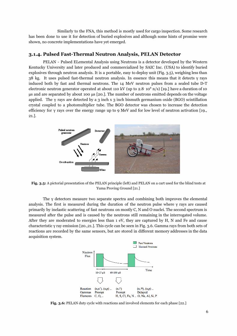
3.1.4. Pulsed FastThermal Neutron Analysis, PELAN Detector
PELAN Pulsed ELemental Analysis using Neutrons is a detector developed by the Western Kentucky University and later produced and commercialized by SAIC Inc. (USA) to identify buried explosives through neutron analysis. It is a portable, easy to deploy unit (Fig. 3.5), weighing less than 38 kg. It uses pulsed fastthermal neutron analysis. In essence this means that it detects γ rays induced both by fast and thermal neutrons. The 14 MeV neutron pulses from a sealed tube DT electronic neutron generator operated at about 110 kV (up to 2.8⋅108 n/s) [19.] have a duration of 10 μs and are separated by about 100 μs [20.]. The number of neutrons emitted depends on the voltage applied. The γ rays are detected by a 3 inch x 3 inch bismuth germanium oxide (BGO) scintillation crystal coupled to a photomultiplier tube. The BGO detector was chosen to increase the detection efficiency for γ rays over the energy range up to 9 MeV and for low level of neutron activation [19., 21.].
Fig. 3.5: A pictorial presentation of the PELAN principle (left) and PELAN on a cart used for the blind tests at Yuma Proving Ground [21.]
The γ detectors measure two separate spectra and combining both improves the elemental
analysis. The first is measured during the duration of the neutron pulse where γ rays are caused primarily by inelastic scattering of fast neutrons on mostly C, N and O nuclei. The second spectrum is measured after the pulse and is caused by the neutrons still remaining in the interrogated volume. After they are moderated to energies less than 1 eV, they are captured by H, N and Fe and cause characteristic γ ray emission [20.,21.]. This cycle can be seen in Fig. 3.6. Gamma rays from both sets of reactions are recorded by the same sensors, but are stored in different memory addresses in the data acquisition system.
Fig. 3.6: PELAN duty cycle with reactions and involved elements for each phase [22.]
6

The unit can be operated remotely from a distance of up to 45 m and can operate for up to 6 hours on its internal battery. The separate measurements take 5 min and during that time an 8 m exclusion zone is established due to radiation safety.
The International Atomic Energy Agency (IAEA) evaluated PELAN as a mine confirmation sensor in November 2002 near Zagreb, Croatia, at a test minefield of the Croatian Mine Action Center. The evaluation included one type of antitank (AT) mine, and three types of antipersonnel (AP) mines (Table 3). The AT mines were buried up to 20 cm deep and AP mines at depths up to 15 cm. The soil moisture varied between 25% and 29% (weight) [21.].
Mine type Explosive mass (g)
Total mass (g)
Explosive Casing
TMM1 5600 TNT + tetryl booster Metal
PMA2 100 135 TNT + RDX booster Plastic
PMA3 35 183 TNT Plastic
PMA1 200 400 TNT Plastic
Table 3: Characteristics of landmines used in the PELAN evaluation in Croatia [21.]
PELAN checked 127 marked locations that could contain one of the mines. The results were the following: probability of detection Pd = 0.85 and probability of false alarm Pfa = 0.23 and a report by the IAEA concluded that PELAN should have no problems recognizing AT mines buried at depths of 15 cm or less an AP mines buried at depths of 10 cm or less [21.] and has thus demonstrated great potential for humanitarian demining.
Another series of blind tests of PELAN as a landmine confirmation sensor were performed by
the US Department of Defense at Yuma Proving Ground (Fig. 3.5) in 2003. Several types of AT mines were buried at various depths and with different types of overburden. Both types (plastic or metal casing) of mines were used. For the blind test a 100 marked locations were tested and prior to the tests 13 calibration locations, either containing a mine or not, were examined. Based on calibration results the PELAN decision tree was adjusted to fit the calibration data. The results were the following: probability of detection Pd = 0.90 and probability of false alarm Pfa = 0.14 [21.].
3.2. Neutron Moderation and Backscattering
Examining the ground with a fast neutron beam and analyzing backscattered neutrons (Fig. 3.7) yields information on hydrogen anomalies in the inspected area. The method is based on the fact that dry sand contains very little hydrogen compared to the contents of plastic anti personnel (AP) mines. Hydrogen content in AP mines ranges in 4050 % of atoms (2535 % in the explosive and 5565 % in the plastic casing) [20.], which means that a AP mine buried in dry sand presents a noticeable anomaly in hydrogen footprint. This anomaly can be detected by examining the flux of moderated and backscattered neutrons. With hydrogen being one of the most efficient neutron moderators (Table 4), elastically scattered neutrons lose the most energy when they scatter on hydrogen nuclei. Consecutive scattering moderates neutrons to thermal energies resulting in backscattered thermal neutrons. Since neutrons are electrically neutral and also don’t interact with electrons, indirect methods of detection, where a neutron interacts with a nucleus to result in a charged particle, have to be used. Gasbased neutron detectors such as the 3He proportional tube are well suited for thermal neutron detection.
7

Moderator Average logarithmic energy loss ξ
Average number of collisions to moderate a
neutron from 2 MeV to 1 eV
H 1.0 14
D 0.725 20
H20 0.920 16
C 0.158 91
Na 0.084 171
Fe 0.035 411
Table 4: Several moderators with an average logarithmic energy loss and a number of collisions, on average, to moderate a neutron from 2 MeV to 1 eV [23.].
Fig. 3.7: Neutron backscattering diagram [13.]
Since this method is based on the detection of hydrogen anomalies it is fundamentally flawed
for detection of mines in soil with high contents of water (over 10%). This limits the use of the method to arid lands, where dry sand dominates the ground composition. Regardless of these limitations there is a number of experimental detectors in various phases of development. Among others: Delft University Neutron Backscattering LAndmine Detector (DUNBLAD), Detection and Imaging of Antipersonnel Landmines by Neutron Backscattering Technique (DIAMINE), HYdrogen Density Anomaly Detector (HYDAD) and Egypt SCAnning LAnd mine Detector (ESCALAD). The main advantage of this method is its high speed of operation. In case of a sufficiently strong neutron source, anomalies can be identified within seconds or even less and a detector can be made comparable (in speed) to a metal detector. This suggests a potential for use in scanning detectors and not only as a confirmation tool.
3.2.1. ESCALAD Detector
The Egypt SCAnning LAndmine Detector (ESCALAD) is a result of an IAEA supported cooperation between the Reactor and Neutron Physics Department of the Nuclear Research Center of the Egyptian Atomic Energy Authority and Delft University of Technology (Netherlands). It is a trolley mounted system, based on the Delft University Neutron Backscattering Imaging Detector (DUNBID).
To detect backscattered thermal neutrons the first version of the system used an array of 16 3He proportional tubes (100 cm long and 2.5 cm in diameter) fixed in an aluminum tray (140 cm x 75 cm x 6 cm) divided into two equal groups separated by 15 cm where the neutron source / sources were placed during operation. The 3He tubes were shielded by a Cd sheet to prevent detection of thermal neutrons coming from the top and sides [24.]. 3He tubes are sensitive mainly to thermal neutrons through the reaction: 3He + n → p + T + 764 keV where the neutron causes the breakup of the 3He nucleus into a proton and a triton with the excess energy distributed between them. The3He pressure was 10 bar and neutron detection efficiency varies from 1 for thermal energy down to 104 for neutrons in the MeV energy range [25.]. The layout of the detector was similar to the one seen in Fig. 3.8. The array of 3He tubes forms a 2D imaging detector. The coordinate value along the scanning direction is
8

determined by which tube registers the event and the coordinate perpendicular to the scan direction (along the tube length) is determined by charge division. The total sensitive detector area is about 100 x 44 cm2.
As a neutron source two PuαBe sources with a neutron emission of about 106 n/s were fixed in the gap between the 3He tubes groups separated by 50 cm. Two cylindrical steel attenuators 3 cm thick were placed under the sources to flatten to some extent the distribution of fast neutrons impinging into the ground. Also two specially designed and constructed graphite reflectors were used above the neutron sources to enhance the number of fast neutrons incident on the ground [24.]. Initial tests were also performed with a single central source by using 252Cf, PuαBe and a DD neutron generator.
The detector was mounted on a specially designed trolley powered by an electric motor capable of moving forward and backward at speeds ranging from 3 mm/s to 50 cm/s. Two additional electric motors were employed to shift the detector tray from side to side and to change the distance between the detectors and the ground [24.].
Fig. 3.8: A cross section of a scanning neutron backscattering land mine detector [25.]
When in operation the detector is moving at a standoff distance of 10 cm above the ground.
Detected neutrons are processed and used to compile an image of the thermal neutron flux emerging from the ground. Counts were stored according to the measured positions in a 32 x 256 array of pixels with a pixel size of 3.3 cm x 3.4 cm. The maximum count possible with the first version electronics was 2⋅105 c/s which corresponds to a maximum source strength of about 6⋅107 n/s [25.].
In the raw image the mines are not easily distinguishable and therefore an elaborate image analysis has to be performed. The raw data of the image has three components:
1. Signal from the mine (if present). 2. Signal caused by neutrons scattering from the soil. 3. Signal from fast neutrons directly from the source.
Components 2 and 3 comprise a background in the image and have to be eliminated for proper mine detection [25.]. The first step in background removal is to remove the fast neutron signal which is an intrinsic system property. It has been measured by lifting the detector about 1.5 m above the ground and registering the neutron flux for each tube in the array. The second step is to remove the signal from the neutrons scattered from the soil. This can be carried out during a scan and is done by analysing the statistical fluctuations of the pixel contents. The third step in the analysis uses the “matched filtering” method to recognize and locate the hot spots. Effects of the image analysis steps on the image can be seen in Fig. 3.9. Second and third step are described in more detail in [25.].
The initial testing of the first ESCALAD version showed antitank mines could be detected up to depths of 25 cm and antipersonnel mines at depths up to 15 cm at scanning speed of 30 mm/s with a single 252Cf source (1.6⋅105 n/s). The mine is best detected by the software when the mine’s signal is fully included in the image, which means that the mine cannot be too far displaced horizontally from the center of the scanning path. This reduces the effective scanning width to about 30 cm [25.], but this width can be somewhat enlarged with the use of two neutron sources. Detection success being
9
dependant on the backscattered neutron flux means that the scanning speed can be improved even more by the use of stronger sources.
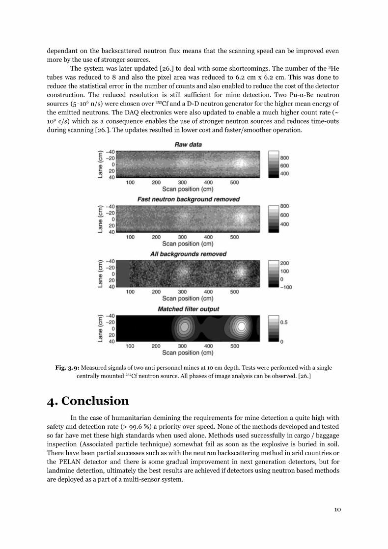
The system was later updated [26.] to deal with some shortcomings. The number of the 3He tubes was reduced to 8 and also the pixel area was reduced to 6.2 cm x 6.2 cm. This was done to reduce the statistical error in the number of counts and also enabled to reduce the cost of the detector construction. The reduced resolution is still sufficient for mine detection. Two PuαBe neutron sources (5⋅106 n/s) were chosen over252Cf and a DD neutron generator for the higher mean energy of the emitted neutrons. The DAQ electronics were also updated to enable a much higher count rate (~ 109 c/s) which as a consequence enables the use of stronger neutron sources and reduces timeouts during scanning [26.]. The updates resulted in lower cost and faster/smoother operation.
Fig. 3.9: Measured signals of two anti personnel mines at 10 cm depth. Tests were performed with a single
centrally mounted 252Cf neutron source. All phases of image analysis can be observed. [26.]
4. Conclusion In the case of humanitarian demining the requirements for mine detection a quite high with
safety and detection rate (> 99.6 %) a priority over speed. None of the methods developed and tested so far have met these high standards when used alone. Methods used successfully in cargo / baggage inspection (Associated particle technique) somewhat fail as soon as the explosive is buried in soil. There have been partial successes such as with the neutron backscattering method in arid countries or the PELAN detector and there is some gradual improvement in next generation detectors, but for landmine detection, ultimately the best results are achieved if detectors using neutron based methods are deployed as a part of a multisensor system.
10
5. References
1. Giancarlo Nebbia, Juergen Gerl: Detection of buried landmines and hidden explosives using neutron, Xray and gammaray probes
2. Joel Kositsky, Russell Cosgrove, Charles Amazeen, Peyman Milanfar: Results from a forwardlooking GPR mine detection system
3. J. B. Miller, G. A. Barrall: Explosives Detection with Nuclear Quadrupole Resonance 4. A. Linderhed, M. Lundberg, S. Nyberg, S. Sjoekvist, M. S.G. Uppsaell: Analysis of optical
measurements of real minefields
5. Wikipedia: Californium isotopes (https://en.wikipedia.org/wiki/Isotopes_of_californium, 5.5.2017) 6. Taner Uckan, José MarchLeuba, Danny Powell, James D. White, Joseph Glaser: 241AmBe Sealed
Neutron Source Assessment Studies for the Fissile Mass Flow Monitor
7. Wikipedia: Neutron Generator (https://en.wikipedia.org/wiki/Neutron_generator, 10.5.2016) 8. Ying Wu, University of California, Berkeley, Doctorate thesis :Development of a Compact Neutron
Generator to be Used For Associated Particle Imaging Utilizing a RFDriven Ion Source (2009) 9. Wikipedia: Inelastic scattering (https://en.wikipedia.org/wiki/Inelastic_scattering, 5.5.2016) 10. J.E. McFee: A multisensor mine detector for peacekeeping Improved Landmine Detector Concept
(ILDC)
11. G. Nardulli, G. Pasquariello: Neutron activation technologies for landmines detection 12. Periodic Table of Elements Sorted by Cross Section (Thermal Neutron Capture)
(http://environmentalchemistry.com/yogi/periodic/crosssection.html 15.5.2016) 13. Giancarlo Nebbia: The Use of Neutron Generators for the Detection of Hidden Explosives and Illicit
Materials (presentation IAEA HQ 13 June 2005) 14. J.E. McFee, A.A. Faust, H.R. Andrews, E.T.H. Clifford, C.M. Mosquera: Performance of an improved
thermal neutron activation detector for buried bulk explosives
15. E.T.H. Clifford, J.E. McFee, , H. Ing, H.R. Andrews, D. Tennant, E. Harper, A.A. Faust: A militarily fielded thermal neutron activation sensor for landmine detection (2008)
16. A.A. Faust, J.E. McFee, C.L. Bowman, C. Mosquera, H.R. Andrews, V.D. Kovaltchouk, H. Ing: Feasibility of fast neutron analysis for the detection of explosives buried in soil
17. Silvia Pesente, University of Padova Doctorate thesis: Development of Inspection Systems using 14 MeV Tagged Neutron Beams
18. Olga Shulyakova, Petr Avtonomov, Valeria Kornienko: New Developments of Neutron Activation Analysis Applications (2015)
19. V. Knapp: Neutron explosive detector and its perspective in humanitarian demining, International Symposium Humanitarian Demining 2004, Sibenik, Croatia, April 2123.
20. F.D. Brooks, A. Buffler, M.S. Allie: Detection of antipersonnel landmines using neutrons and gammarays (2004)
21. G. Vourvopoulos, R.A. Sullivan and D.T. Holslin: Evaluation of PELAN as a Confirmation Sensor for Landmines and Explosives (2008)
22. A. Buffler: Detection of AntiPersonnel Landmines using Neutrons and Gamma Rays, Presentation at Commonwealth Scientific and Industrial Research Organisation (CSIRO)
23. Weston M. Stacey: Nuclear Reactor Physics (Wiley 2001, page 31)
24. R.M. Megahid, V.R. Bom, A.M. Osman: Trolley Mounted Neutron Backscattered System for Landmine Detection (2008)
25. Victor Bom, A. M. Osman, and A. M. Abdel Monem: A Novel Scanning Land Mine Detector Based on the Technique of Neutron Back Scattering Imaging (2008)
26. M. S. Abdelaziem, A. M. Osman, M. M. Ahmed, R. A. M. Rizk, R. M. Megahid: Upgrading the Egyptian Scanning Landmine Detectors (2013)
11