Detection of Hydrogen induced Cracks During In-service ... Ultrasonic Phased Arrays – Assessment...
14
Detection of Hydrogen induced Cracks During In-service inspection of Piping Using Ultrasonic Phased Arrays – Assessment of Fitness for Service Santanu Saha 1, a ; Amaresh Majumder 2, b 1 Intertek-Inspec; PO Box: 6130, Sharjah, UAE; 2 Intertek-Inspec; PO Box: 6130, Sharjah, UAE; a [email protected]; b [email protected] ABSTRACT: Hydrogen induced cracking in Carbon steel in sour service is a common damage mechanism, particularly in older steel piping, which was generally non-compliant to NACE 0175. During in- service inspection of such an old pipeline in a gas processing plant, numerous mid wall indications were observed while performing conventional Pulse-echo ultrasonic examination. Previously it was assumed as laminations and stringers in the piping material during manufacturing process; however for reconfirmation, an automated phased array examination has been performed on the same location with longitudinal waves and several indications with depths around mid-wall thickness have been observed and recorded. A portion of the affected pipe where indications were observed has been cut and removed from the main pipe after complete shut down and it was observed that several blisters with cracks have been occurred in the inside surface of the piping which were not visible from the outer surface. Further assessment revealed those portions of the pipes were affected by Hydrogen induced blistering and related cracking mechanisms. A Fitness for Service assessment has been carried in accordance with API 579-1/ ASME API FFS-1 for the remaining areas of the piping and report submitted for subsequent action. Keywords: Hydrogen Induced Cracking; Blisters; Fitness for Service National Seminar & Exhibition on Non-Destructive Evaluation, NDE 2014, Pune, December 4-6, 2014 (NDE-India 2014) Vol.20 No.6 (June 2015) - The e-Journal of Nondestructive Testing - ISSN 1435-4934 www.ndt.net/?id=17823
Transcript of Detection of Hydrogen induced Cracks During In-service ... Ultrasonic Phased Arrays – Assessment...
Detection of Hydrogen induced Cracks During In-service inspection of Piping
Using Ultrasonic Phased Arrays – Assessment of Fitness for Service
Santanu Saha1, a ; Amaresh Majumder2, b 1Intertek-Inspec; PO Box: 6130, Sharjah, UAE;
2Intertek-Inspec; PO Box: 6130, Sharjah, UAE; a [email protected];
ABSTRACT:
Hydrogen induced cracking in Carbon steel in sour service is a common damage mechanism,
particularly in older steel piping, which was generally non-compliant to NACE 0175. During in-
service inspection of such an old pipeline in a gas processing plant, numerous mid wall
indications were observed while performing conventional Pulse-echo ultrasonic examination.
Previously it was assumed as laminations and stringers in the piping material during
manufacturing process; however for reconfirmation, an automated phased array examination has
been performed on the same location with longitudinal waves and several indications with depths
around mid-wall thickness have been observed and recorded. A portion of the affected pipe
where indications were observed has been cut and removed from the main pipe after complete
shut down and it was observed that several blisters with cracks have been occurred in the inside
surface of the piping which were not visible from the outer surface. Further assessment revealed
those portions of the pipes were affected by Hydrogen induced blistering and related cracking
mechanisms. A Fitness for Service assessment has been carried in accordance with API 579-1/
ASME API FFS-1 for the remaining areas of the piping and report submitted for subsequent
action.
Keywords: Hydrogen Induced Cracking; Blisters; Fitness for Service
National Seminar & Exhibition on Non-Destructive Evaluation, NDE 2014, Pune, December 4-6, 2014 (NDE-India 2014)
Vol.20 No.6 (June 2015) - The e-Journal of Nondestructive Testing - ISSN 1435-4934www.ndt.net/?id=17823
1. Introduction:
In line survey of an existing sour gas service pipelines running through the gas processing plant
by Ultrasonic Phased Array and Ultrasonic Pulse-echo testing have been utilized. The pipelines
are in service for many years. The piping material is reported to be made from API 5L Gr B. the
materials are reported to be not compliant with NACE MR 0175 and hence not resistant to
Hydrogen cracking. Although they are in service for a long period no major failure was reported
except in one pipeline which was found to be severely affected by the hydrogen blistering & HIC
mechanism. The affected portion was subsequently replaced by a new pipe material.
As a precautionary measure, the Owner wanted to investigate the remaining pipelines to detect
any blistering and HIC in the associated piping prone to the HIC damage. We as an agency for
conducting HIC survey have been awarded with the job.
During the survey, some of the piping has been found with extensive indications from the mid
thickness of the piping material. Some of these indications might be occurred from inherent
inclusions left inside the plate material during rolling, but a large number of the indications are
most probably came from initiation and growth of hydrogen inside the pipe material (HIC
damage). Stepwise cracking were also observed in some of the locations. A comprehensive
report presented to the owner after completion of the survey. The result of Phased Array
scanning of the piping from outside the pipe surface has been presented. Each individual report
contained a piping system/ segment of piping system and the results are displayed in A-scan, B
scan and C scan presentation. A brief analysis is given in each report which described the present
condition of the piping with respect to the presence of internal indications and displayed in the
presentations.
2. Hydrogen Induced Cracking Mechanisms:
The occurrence of hydrogen embrittlment is a much researched phenomenon, known to cause
mechanical property degradation and catastrophic failures. The ductility loss brought about by
hydrogen ingress is encountered even in unstressed bodies where such cracking is termed
hydrogen induced cracking (HIC) and is in phenomenological contrast to catastrophic failures
encountered by stressed bodies subjected to hydrogen producing environments. This form of
cracking is especially detrimental and often observed in oil country tubular goods (OCTG) which
are subjected to sour gas. Consequently, the significance of HIC is most appreciated at various
stages of oil extraction, transportation and storage. The chemical and metallurgical genesis of
HIC, its harmful impact on material and component integrity are discussed elsewhere. It has been
noted that MnS inclusions are extremely harmful to this form of cracking. Similarly, centreline
segregation in the ingot stage and de-oxidation practices during steelmaking were found to affect
HIC.

There are several categories of hydrogen phenomena that are localized in nature. Atomic
hydrogen, and not the molecule, is the smallest atom and it is small enough to diffuse readily
through a metallic structure. When the crystal lattice is in contact or is saturated with atomic
hydrogen, the mechanical properties of many metals and alloys are diminished. Nascent atomic
hydrogen can be produced as a cathodic reaction when certain chemical species are present
which act as negative catalysts (i.e. poisons) for the recombination of atomic to molecular
hydrogen as shown in the following equation.
If the formation of molecular hydrogen is suppressed, the nascent atomic hydrogen can diffuse
into the interstices of the metal instead of being harmlessly evolved as a gaseous reaction
product. There are many chemical species which poison this recombination (e.g. cyanides,
arsenic, antimony, or selenium compounds). However, the most commonly encountered species
is hydrogen sulfide (H2S), which is formed in much natural decomposition, and in many
petrochemical processes.
Processes or conditions involving wet hydrogen sulfide i.e. sour services, and the high incidence
of sulfide-induced HIC has resulted in the term sulfide stress cracking (SSC). The SSC of
medium strength steels has been a continuing source of trouble in the oil fields. However, similar
problems are encountered wherever wet hydrogen sulfide is encountered (e.g. acid gas scrubbing
systems, heavy water plants, and waste water treatment).
Various factors are believed to contribute to unlocking the lattice of the metal, such as hydrogen
pressure at the crack tip, the competition of hydrogen atoms for the lattice bonding electrons, the
easier plastic flow and dislocation formation in the metal at the crack tip in the presence of
hydrogen, and the formation of certain metal hydrides in the alloy. Generally the presence of
HIC is first evident as blister formation in the piping inner surface (see figure-1). Excessive
accumulation of molecular hydrogen in the confined spaces of the inclusions can cause the
internal pressure at the location to exceed the tensile strength in that particular zone resulting in
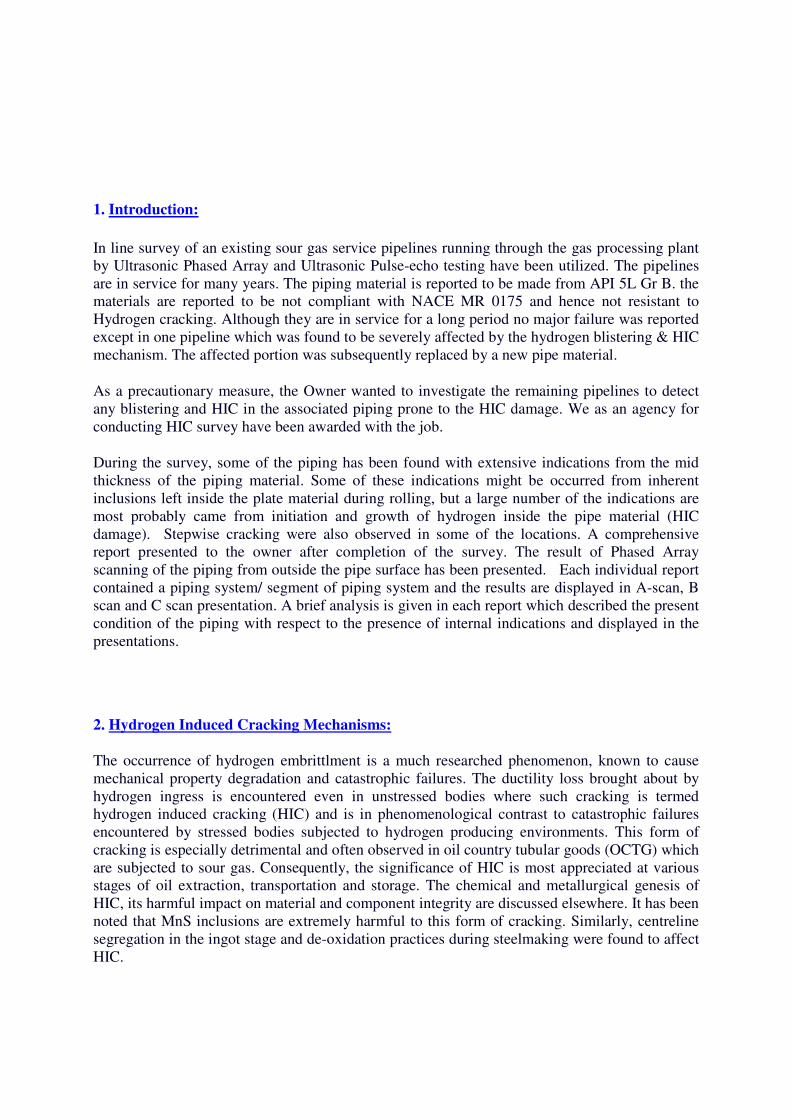
cracking initiated from the blister (see figure-2). A typical characteristic of HIC is stepwise
cracking; which is caused by link up of several affected zones at different depth levels inside the
metal wall (see figures 3 & 4).
Figure – 1 (example): Hydrogen blister
formation on pipe surface.
3. Critical Factors for HIC & Blistering (Excerpts from API 571):
The most important variables that affect and differentiate the various forms of wet H2S damage
are environmental conditions (pH, H2S level, contaminants, temperature), material properties
(hardness, microstructure, strength) and tensile stress level (applied or residual). All of these
damage mechanisms are related to the absorption and permeation of hydrogen in steels.
3.1 pH: Hydrogen permeation or diffusion rates have been found to be minimal at pH 7 and
increase at both higher and lower pH. The presence of hydrogen cyanide (HCN) in the water
phase significantly increases permeation in alkaline (high pH) sour water. The following are the
major factors:
• >50 w ppm dissolved H2S in the free water.
• Free water with pH <4 and some dissolved H2S present.
Figure – 2 (example): Typical stepwise
cracking caused by link up of individual
cracks.
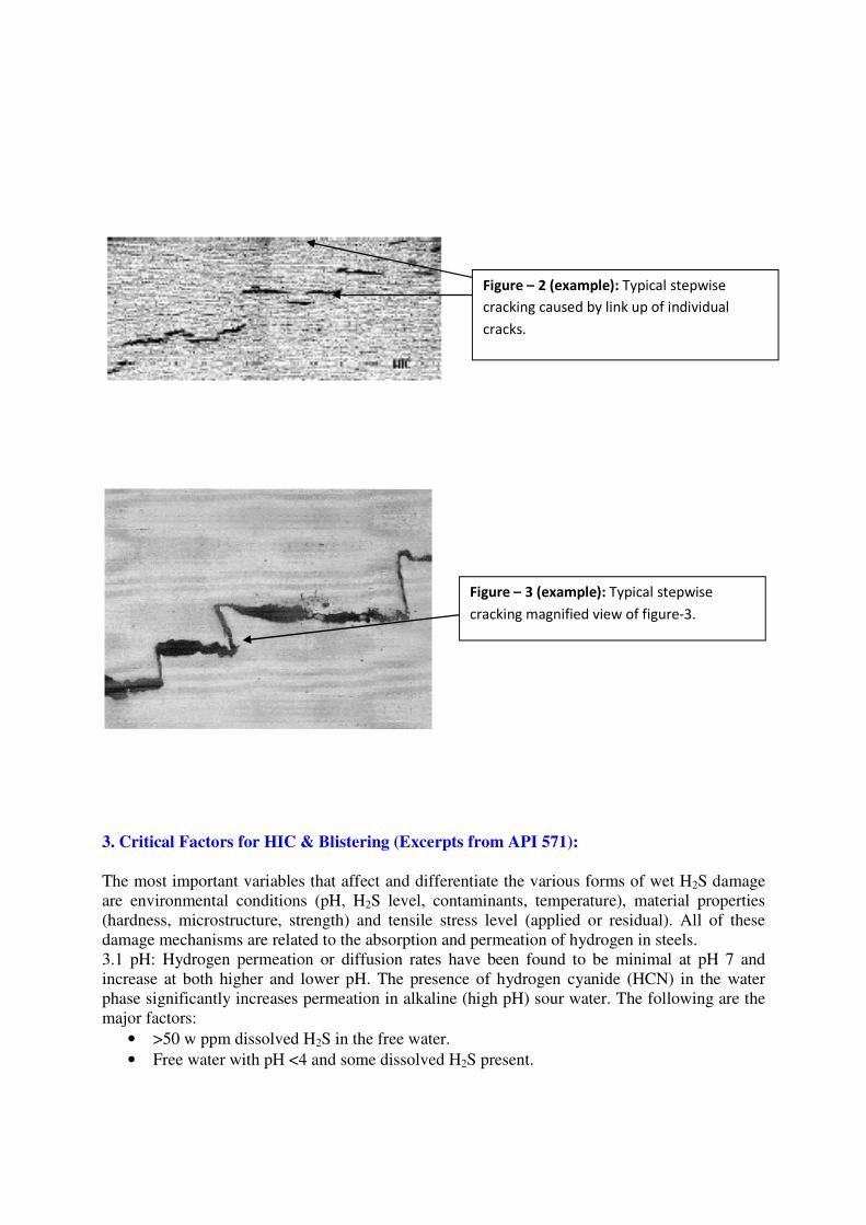
Figure – 3 (example): Typical stepwise
cracking magnified view of figure-3.
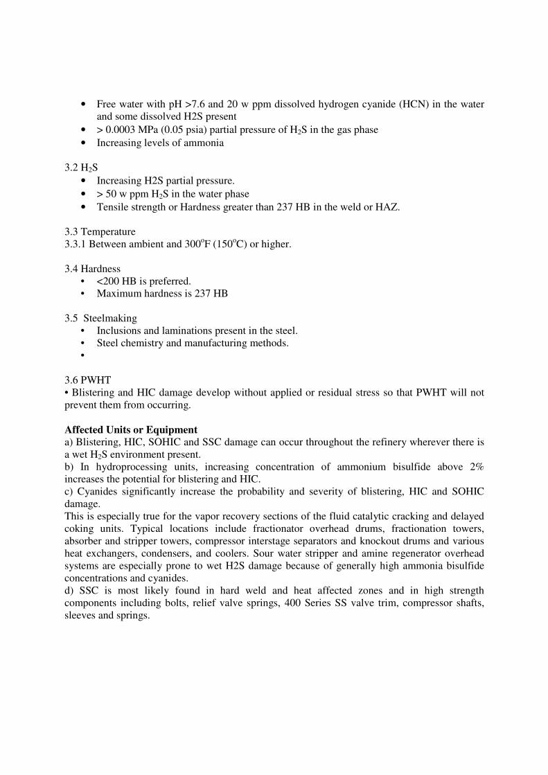
• Free water with pH >7.6 and 20 w ppm dissolved hydrogen cyanide (HCN) in the water
and some dissolved H2S present
• > 0.0003 MPa (0.05 psia) partial pressure of H2S in the gas phase
• Increasing levels of ammonia
3.2 H2S
• Increasing H2S partial pressure.
• > 50 w ppm H2S in the water phase
• Tensile strength or Hardness greater than 237 HB in the weld or HAZ.
3.3 Temperature
3.3.1 Between ambient and 300oF (150
oC) or higher.
3.4 Hardness
• <200 HB is preferred.
• Maximum hardness is 237 HB
3.5 Steelmaking
• Inclusions and laminations present in the steel.
• Steel chemistry and manufacturing methods.
•
3.6 PWHT
• Blistering and HIC damage develop without applied or residual stress so that PWHT will not
prevent them from occurring.
Affected Units or Equipment
a) Blistering, HIC, SOHIC and SSC damage can occur throughout the refinery wherever there is
a wet H2S environment present.
b) In hydroprocessing units, increasing concentration of ammonium bisulfide above 2%
increases the potential for blistering and HIC.
c) Cyanides significantly increase the probability and severity of blistering, HIC and SOHIC
damage.
This is especially true for the vapor recovery sections of the fluid catalytic cracking and delayed
coking units. Typical locations include fractionator overhead drums, fractionation towers,
absorber and stripper towers, compressor interstage separators and knockout drums and various
heat exchangers, condensers, and coolers. Sour water stripper and amine regenerator overhead
systems are especially prone to wet H2S damage because of generally high ammonia bisulfide
concentrations and cyanides.
d) SSC is most likely found in hard weld and heat affected zones and in high strength
components including bolts, relief valve springs, 400 Series SS valve trim, compressor shafts,
sleeves and springs.

4. Phased Array Techniques for detecting HIC:
Ultrasonic phased array technique is the most advanced technique to detect and size the HIC
flaws in line pipe steels. A linear 1D array probe has been used. See figure-5. While
conventional ultrasonic systems use one crystal, Phased arrays use an array of crystals to
generate the ultrasonic waves which is controlled by the software for time delays and can be
focused to a definite depth. Various nomenclatures of Phased Array 1D probe is shown in figure-
6.
Depending on the type of product (piping, structures, and other product forms) and locations
(base metal, welds) different scan can be selected to enhance better detect-ability. For scanning a
length of piping, a normal longitudinal scan can be selected based on the previous experience of
the type and characteristics of HIC found in the similar piping. See figures 5, 6, 7 & 8 as
examples of indications which typically found in the HIC affected piping.
Figure – 4 (example): Linear 1D array probe
for Phased Array.
Figure – 5 (example): Linear 1D array probe
for Phased Array. Active and passive
dimensions.

5. Phased array survey report:
ASME code for pressure vessels and piping (ASME Sec VIII Div. 1 & 2, ASME B 31 code) has
approved the use of Phased Arrays for detection of flaws in welds and components in pressure
vessels and piping quite a few years back. Although ASME BPV code mainly governs the area
during the manufacturing process, same methodology can be used in in-service inspection also.
The phased array report has been prepared in accordance with the requirements of ASME Code
of construction keeping all the essential parameters of the reporting.
6. Application of Fitness for Purpose (API 579-1):
API 579-1 describes different levels of assessment of HIC and Hydrogen blisters for components
subject to HIC damage.
1. Level 1 Assessment.
2. Level 2 Assessment.
3. Level 3 Assessment.
For all levels, the required data and measurements for assessment of HIC damage are listed
below (refer to Figure-1).
a) HIC Spacing to Nearest HIC or Blister, edge-to-edge spacing between HIC damage
and the nearest HIC or blister damage (LH)
b) HIC Spacing to Weld Joints (LW)
c) HIC Spacing to Major Structural Discontinuities (Lmsd)
d) HIC Through-Thickness Extent of (WH)
e) Minimum Remaining Wall Thickness of Undamaged Metal, Internal Side (tmm-ID)
f) Minimum Remaining Wall Thickness of Undamaged Metal, External Side (tmm-OD)
Figure-6: Standard sectorial
view of the beam skewing and
typical indications.
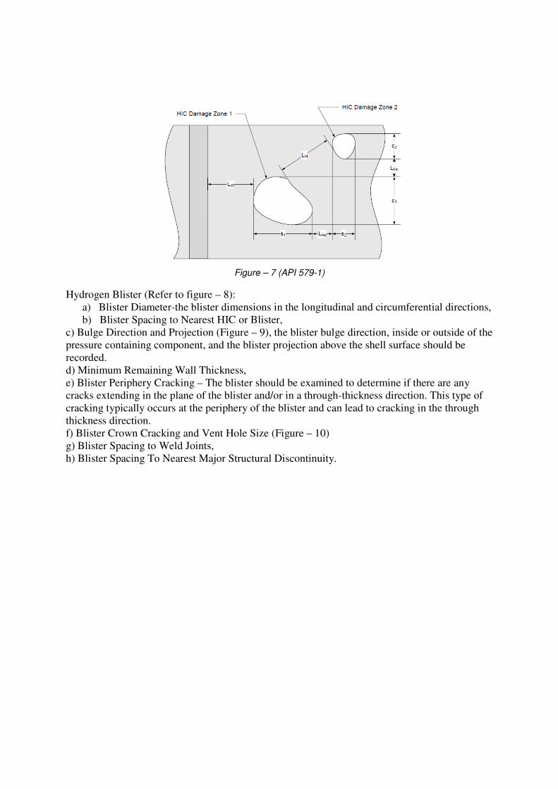
Figure – 7 (API 579-1)
Hydrogen Blister (Refer to figure – 8):
a) Blister Diameter-the blister dimensions in the longitudinal and circumferential directions,
b) Blister Spacing to Nearest HIC or Blister,
c) Bulge Direction and Projection (Figure – 9), the blister bulge direction, inside or outside of the
pressure containing component, and the blister projection above the shell surface should be
recorded.
d) Minimum Remaining Wall Thickness,
e) Blister Periphery Cracking – The blister should be examined to determine if there are any
cracks extending in the plane of the blister and/or in a through-thickness direction. This type of
cracking typically occurs at the periphery of the blister and can lead to cracking in the through
thickness direction.
f) Blister Crown Cracking and Vent Hole Size (Figure – 10)
g) Blister Spacing to Weld Joints,
h) Blister Spacing To Nearest Major Structural Discontinuity.

Figure – 8 (API 579-1)
Figure – 9 (Blister bulging – actual photograph)
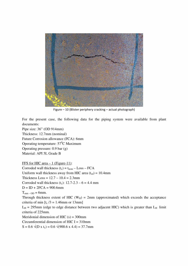
Figure – 10 (Blister periphery cracking – actual photograph)
For the present case, the following data for the piping system were available from plant
documents:
Pipe size: 36” (OD 914mm)
Thickness: 12.7mm (nominal)
Future Corrosion allowance (FCA): 6mm
Operating temperature: 570C Maximum
Operating pressure: 0.9 bar (g)
Material: API 5L Grade B
FFS for HIC area – 1 (Figure-11):
Corroded wall thickness (tc) = tnom – Loss – FCA
Uniform wall thickness away from HIC area (trd) = 10.4mm
Thickness Loss = 12.7 – 10.4 = 2.3mm
Corroded wall thickness (tc): 12.7-2.3 – 6 = 4.4 mm
D = ID + 2FCA = 900.6mm
Tmm – OD = 6mm.
Through thickness extent of HIC (WH) = 2mm (approximated) which exceeds the acceptance
criteria of min [tc /3 = 1.46mm or 13mm]
LH = 295mm (edge to edge distance between two adjacent HIC) which is greater than LH limit
criteria of 225mm.
Meridonial dimension of HIC (s) = 300mm
Circumferential dimension of HIC I = 310mm
S = 0.6 √(D x tc) = 0.6 √(900.6 x 4.4) = 37.7mm
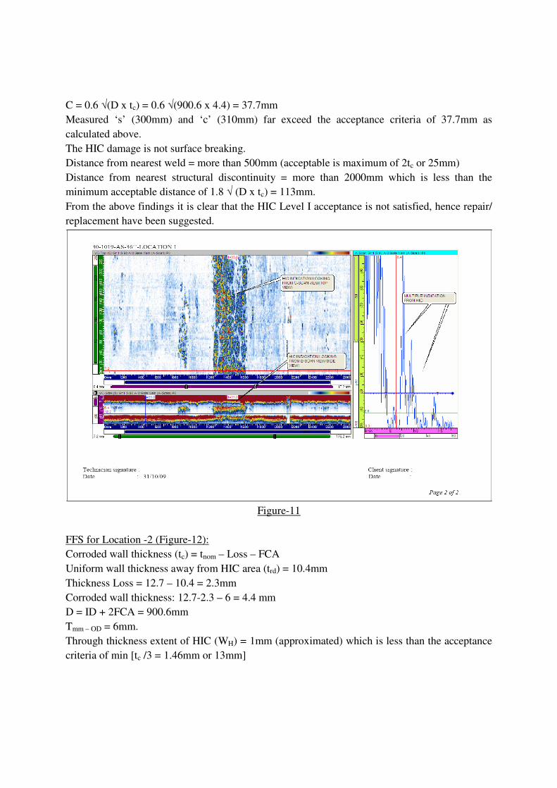
C = 0.6 √(D x tc) = 0.6 √(900.6 x 4.4) = 37.7mm
Measured ‘s’ (300mm) and ‘c’ (310mm) far exceed the acceptance criteria of 37.7mm as
calculated above.
The HIC damage is not surface breaking.
Distance from nearest weld = more than 500mm (acceptable is maximum of 2tc or 25mm)
Distance from nearest structural discontinuity = more than 2000mm which is less than the
minimum acceptable distance of 1.8 √ (D x tc) = 113mm.
From the above findings it is clear that the HIC Level I acceptance is not satisfied, hence repair/
replacement have been suggested.
Figure-11
FFS for Location -2 (Figure-12):
Corroded wall thickness (tc) = tnom – Loss – FCA
Uniform wall thickness away from HIC area (trd) = 10.4mm
Thickness Loss = 12.7 – 10.4 = 2.3mm
Corroded wall thickness: 12.7-2.3 – 6 = 4.4 mm
D = ID + 2FCA = 900.6mm
Tmm – OD = 6mm.
Through thickness extent of HIC (WH) = 1mm (approximated) which is less than the acceptance
criteria of min [tc /3 = 1.46mm or 13mm]
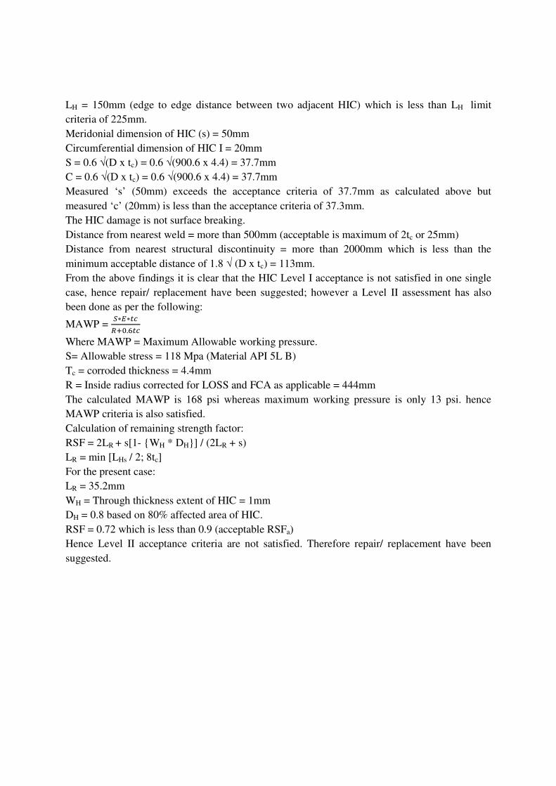
LH = 150mm (edge to edge distance between two adjacent HIC) which is less than LH limit
criteria of 225mm.
Meridonial dimension of HIC (s) = 50mm
Circumferential dimension of HIC I = 20mm
S = 0.6 √(D x tc) = 0.6 √(900.6 x 4.4) = 37.7mm
C = 0.6 √(D x tc) = 0.6 √(900.6 x 4.4) = 37.7mm
Measured ‘s’ (50mm) exceeds the acceptance criteria of 37.7mm as calculated above but
measured ‘c’ (20mm) is less than the acceptance criteria of 37.3mm.
The HIC damage is not surface breaking.
Distance from nearest weld = more than 500mm (acceptable is maximum of 2tc or 25mm)
Distance from nearest structural discontinuity = more than 2000mm which is less than the
minimum acceptable distance of 1.8 √ (D x tc) = 113mm.
From the above findings it is clear that the HIC Level I acceptance is not satisfied in one single
case, hence repair/ replacement have been suggested; however a Level II assessment has also
been done as per the following:
MAWP = �∗�∗��
���.��
Where MAWP = Maximum Allowable working pressure.
S= Allowable stress = 118 Mpa (Material API 5L B)
Tc = corroded thickness = 4.4mm
R = Inside radius corrected for LOSS and FCA as applicable = 444mm
The calculated MAWP is 168 psi whereas maximum working pressure is only 13 psi. hence
MAWP criteria is also satisfied.
Calculation of remaining strength factor:
RSF = 2LR + s[1- {WH * DH}] / (2LR + s)
LR = min [LHs / 2; 8tc]
For the present case:
LR = 35.2mm
WH = Through thickness extent of HIC = 1mm
DH = 0.8 based on 80% affected area of HIC.
RSF = 0.72 which is less than 0.9 (acceptable RSFa)
Hence Level II acceptance criteria are not satisfied. Therefore repair/ replacement have been
suggested.

Figure – 12
7. Advantages of Phased Arrays:
The documents that prescribe Engineering Critical Assessment and fitness for purpose of a
component take into account the capability and uncertainty of various NDT methods to be used.
The increasing use of fracture mechanics and engineering critical assessment philosophy has had
a major impact on the use of reliable ultrasonic methodology with good reliability and precision
in flaw sizing.
Phased array ultrasonic has specific advantages compared with other Ultrasonic methods:
1. Focussed beam with higher SNR (signal to noise ratio).
2. S-Scan imaging (sectorial scan) of the component makes interpretation easy and
straightforward.
3. Multiple beams with high angular resolution leads to a high POD (Probability of
Detection)
4. Data analysis is easier than ToFD (Time of Flight Diffraction Technique)
5. Data can be plotted into a 2D/3D drawing.
6. Repeatability and reproducibility of results.
Phased Array Ultrasonic can help to get most of the data required as stated above in conjunction
with visual inspection and good precision of results can be obtained which is the basis for
reliable FFS and ECA assessment.
8. Conclusion:
The intention of this document is that a good quality of flaw data had been collected for the
present job which would not be possible by using any other NDT method/ technique. The quality
and accuracy of the flaw data can be a very god data base for ECA and FFS analysis. Moreover
the results obtained can be used for future monitoring of pipelines and any propagation and
growing of flaws before they can grow to a critical size and cause catastrophic failure. Another
important consideration is that it can be carried out while the component is in service without
any interruption in the service unless the temperature of component very high typically more
than 600C, although some probes/ arrangement are available which can perform in the higher
temperature also.
9. References:
1. API 579-1: Fitness for service.
2. BS 7910: Guide on the methods for assessing the acceptability of flaws in metallic structures.
3. ASM Handbook Volume 11: Failure Analysis & Prevention.
4. ASM Handbook Volume 13C: Corrosion: Environments & Industries.
5. Hydrogen Embrittlement & Stress Corrosion Cracking: Gibala and Hehemann
6. Olympus Handbook: Advances in Phased Array Ultrasonic Applications.
7. API 571: Damage Mechanism Affecting Fixed Equipment in Refining Industry.