Details of Work Nama Creek Group Sudbury Contact Mines ItdV · Nama Creek Group Sudbury Contact...
15
-4- : " ' -.. . ^ Details of Work Nama Creek Group Sudbury Contact Mines ItdV Prospecting and Stripping. M.C* Hubble G. White. s Worked 25 .-',' ; ' ,* 25 : -.;v,,', /' '" v ' ' - 25x4 26X4 Credit ' •••' '•i .."Jop'^ : .^'^'''lOQV Geological Mapping P.A. Chubb s end Reports P. A. Chubb - 5 5x4 -3x4 Tota l shif ts ored IV* This work is being fepplled as 19 ittaji days credit 'f for each of the following 12 olaipWf TB,483Q2-85-84, Tg, ^ f 48403-4-5-6-7-8-9-10-11. "" ' : , ; '/-1 . . : '- . : : . , ; ^.; ; ;rt .. " , -',- v ; "' ; ,:; " -^ P .A. Chubb^ P; Sjig.
Transcript of Details of Work Nama Creek Group Sudbury Contact Mines ItdV · Nama Creek Group Sudbury Contact...

-4- : " ' -.. . ^
Details of Work
Nama Creek Group
Sudbury Contact Mines ItdV
Prospecting and Stripping.
M.C* Hubble G. White.
s Worked25 .-',' ; ' ,*25 : -.;v,,',
/' '" v ' ' -
25x426X4
Credit' •••' '•i .."Jop'^:.^'^'''lOQV
Geological Mapping
P.A. Chubb
s end Reports
P. A. Chubb -
5 5x4
-3x4
Tota l shif ts ored IV*
This work is being fepplled as 19 ittaji days credit 'f
for each of the following 12 olaipWf TB,483Q2-85-84, Tg, ^ f
48403-4-5-6-7-8-9-10-11. "" ' : , ; '/-1 . . : '- . : : . , ; ^.;; ;rt .. " , -',- v; "' ; ,:; " -^
P .A. Chubb^ P; Sjig.
63.451 MANITOUWADGE LAKE
r
020 S
R g P O R T IN D S X
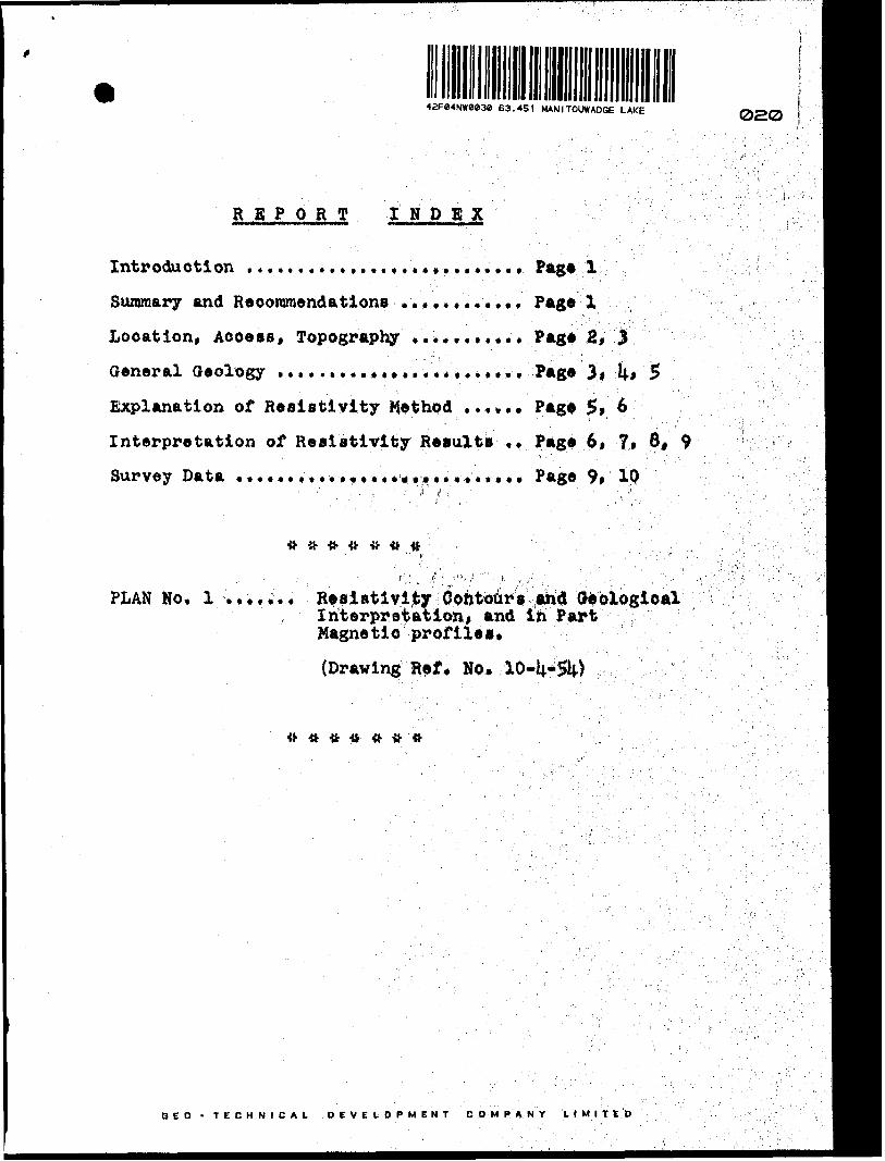
Introduction . . . . , . . . . . . . .. . . . ,,. . . .. . . , Page l
Summary and Recommendations .,.***,*.... Page 2.
Location, Access, Topography *..*....*** Page 2, 3
General Geology . . . . . . . . . . . . . . . , . , , . * , . , Page 3, l\-t S
Explanation of Resistivity Method . .*... Pag* 2* 6
Interpretation of Resistivity Results ,, Page 6, 7* 8* 9
Survey Data . . . * . * , . . . . , * . . . * . . * . . * . . . . * Page 9, 10
-tt
PLAN No. l ....... Realfltlvity Contours and Geological, Interpretation, and in Part
Magnetic profiles*
(Drawing Ref, No* 10-
GEO -TECHNICAL DEVELOPMENT COMPANY LIMITED

Contact Mines Limited 1010, 100 Adelaide Street West
Toronto, Ontario
Gentlemeni
The following report describes the
resistivity and magnetic surveys conducted on your property
located in the Manitouwadge Lake area, Nama Creek Section,
District of Thunder Bay, Port Arthur Mining Division, Ontario.
The survey was conducted by the Oeo-Technical Development
Company Limited during the period from March 8th to Apjpll
7th, 195U* The results are shown on Plan No. l accompanying
this report.
Summary and Reooramendations
Three good electrical conductors are shown by the
survey. Magnetic highs occur at the contacts of the zones,
which strike in a general N, 700 S* direction* Th* are^a *
appears to have been faulted in a north-south direction.
There is also a possibility of folding.
The three conductors are magnetic and have suf
ficient continuity and strength to contain concentrations
of sulphides. Geological mapping, prospecting and diamond
drilling are recommended* ; ;. ' . . . . '' ' t ' . - ', . . -,
Two possible diamond drill sites are shown onP--'-, ' " : : ' ' -'- : •••^: ! : i 'vPlan No. 1. The first hole is f o be drilled through^tht
center of "A" zone with a south b nringj second hole through
the center of "B" Bon* with a south bearing. These diaiiond
drill holes may follow preliminary ground work recommended
above, should the results of woVlrork warrant further
exploration. - . '.j; ' . ; \' '--':, .'.,: T,';";;"r; V; \ :," ; ,
BED - TECHNICAL b E'V E L O *" tjj E N T COMPANY LIMITE

- 2 -
Location j Access, Topography
The Sudbury Contact Mine a Limited property oom-
priaea 12, [4.0 -acre unsurveytd Mining claims numbered a*
follows: T.B. I|8l4.07, 14.814.06, 481*05, W08, 1*81*11* I*8k0lu 1*81*09, 1*81*10, 1*81*03, 1*8382, 1*8383.
The claims group adjoina Paige Petroleun Mad tad
property on the ea at, Mentor Exploration le Development
Company Limited on the neat* Maloney ataked group on the
south, and Cameron ataked group on the north.
Access to the property la made from Camp 12 of
the Marathon Paper Company Limited, which ia connected by
a first-clasa gravel road to Stevens, Ontario, on the
C.N.R. The distance south from Stevens ia approximately
30 mi le a. The group li e a approximately 5 mile a south-
east from Camp 12, and a logging road from the Camp awlnga
to within one-half a mile of the south boundary of the olaima
group. The winter route to Lun-JBeho Mines Limited paaaea
close to the aouth boundary. Direct aeoeaa from Camp 12
to the center of the property ia made by helicopter with
landings being made on a small pond in the center of tat
property (Eric Lake) . The survey eamp waa located 200 fttt
south of this pond. There are no roads or permanent build
ings on the property. i
The area ia fairly flat with a loir ridge trending
somewhat north of east in the atutfcwast portion of the olaima
group. "Eric Lake", approximately 900 fttt in diameter,
occupies the southwest part of Claim Ho. 1*61*10. A north-
south trending open bog area ooctfiea the southeast part\
of Claim No. 14.83814.. A aouth flowing erttk runs along the
GEO -TECHNICAL DEVELOPMENT COMPANY LIMITED

- 3 -
cevber of this swamp.
The property li forested with a thick cover of
first growth spruce* jaokpine and balsam, with sections of
birch and poplar. The swamp area* are covered with a think
growth of alders. This undergrowth is generally light in
the heavy timber areas. The property lies within the
Marathon Paper Company Limited timber limits.
Heavy snow conditions masked most of the possible
outcrop areas; only a few rock outcrops were visible above
the snow surface. The following field notes war* made on
the geology: At the south boundary 200 feet east ef #3
Post, Claim No, ij.8382 - massive* red granite. Claim Ho,
14.8383* hornblende gneiss j on east boundary strike of gneiss
osity N. 700 E. dip north. Grey and red granite was found
on Line 400 feet west of this location. The outcrops are
located at edge of zone "A". Remainder of the area may show
more outcrops but they are low lying and do not show through
the deep snow cover.
It is advisable to use the present marked footage
pickets where they lie in order to tie in outcrops or diejwmd
drill locations with this survey.
General Geology
The r ocks of the general area are pre-Cambrlan in
age and all are of the igneous type. The oldest formation
is Keewatin which consists chiefly of metamorphosed basie
lavas. A few dikes of basic intrusive* ranging from gabbre
to lamprophyre out t he greenstone! but are pre-granite In ag*.
These older rocks are intruded by a great batholith of granite
GEO - TECHNICAL DEVELOP MENT COMPANY LI M t T E D

and gneiss which covers the greater part of the area and
extends beyond its limits. Thi t intrusive is placed
(tentatively) as Algoman. Quart* and feldspar porphyries
are genetically related to the granite* All the rock* are
intersected by diabase dikes, part of the Keweenawan basis
intrusions. The rock formations of the area nay be clas
sified as follows:
Pleisto***e * Recent: Till tt flu vi o -glacial deposits
Fro-Cambrian: Great unconformity
Keweenalan: Olivine diabase * quarts diabase dikes
Intrusive Contact
ALGOMAN Tt Quarts 6 (feldspar porphyry " * (hornblende Is biotite granite
, (* gneiss
j Intrusive Contaet
KEKWATIHi Wsalt, andesite*, amygdaloidal tt pillow kVaft* amphibolite, aplite, peridotite, iorite ft hornblende schist, subordinate
s of intrusive gabbro le lamprophyre.
rocks are ohiefly basic volcanics
phosea equivalents. Whenever massive lavas
are andesitio to^bajialtic in composition and
aces show pillow or ellipsoidal stvueture.
altered to chlorite and hornblende schists.; . .'-i.'. ; ; ^ '-' :" : ..: ' ' ' - '- '
acts these schists are greatly sheared and-,;'" ' :
in one of these small areas of greenstone,
at its cont** **h granite, that the Geo o Mines Liaited
orebodles oclW* phese greenstone bands show faulting in
a north-sou t^Iirttion. ^ north-south fault offsets the
Oeoo orebodyifsi Ontario Departnent of Mines Vol. ;jQUC,
Part VI t 19*eo,ogy of Huron Bay, White Lake Area, by
Q E O -W H J C A L DEVELOPMENT COMPANY LIMITED

- 5 -
Jas. E. Thompson.)
Detailed geology on the Sudbury Contact Hine a
Limited property was impossible in the winter months. It
is known, however, that sheared granite and granite gneiss
occurs in the vicinity of the eones outlined by the resis
tivity survey. There is a possibility that the sane itself
may represent a sheared greenstone belt carrying sulphides.
This would be the typical geological picture for the area*
A marked linear topographic break shows in the
southeast part of the property. This feature is thought
to be a north-south trending fault which runs through
Claim No.
Explanation of Resistivity Method
The method used by the Oeo -Technical Development
Company Limited is a form of the early resistivity methods
modified by some eight years experience in the field.
In short* a known current is put into the ground
and readings are taken at 50 foot intervals along picket
lines by sensitive vacuum tube voltmeters Measuring the
voltage drop across this interval* Calculations translate
these voltage readings into resistance values in terms of
ohm-centimeters. These are plotted on the nap.
Due to the inhomogeneity of the medium being
examined; i.e., the complexity of the geology and structure,
interpretations are based on experience and a knowledge of
the geological conditions in the area being tested with this
particular method. Where the latter are unknown, the inter
pretation must, of necessity, be limited or very tentative*
GEO -TECHNICAL DEVELOPMENT COMPANY LIMITED

Ho w* Tar, without any geological Information it
la geaarally possible to differentiate between baaded roeka
•uoh aa volcanics, sediments or gneiaa and large bodlaa of
maaaive Intrusive*, dua to tha diff erenee of eleetrleA eea*
due t i vi ty between tha various f leva or bad*. Strike trend*,
folding, etc. ara tharafora readily pi oka d up. In aoaia aaaaa
rook oontaota may ba infarrad*
Shaar or fracture soaas ara relatively bat tar eon-
due t or o, dua to their higher watar content, Where extrene
low resistivity values ara found, graphite or au&phldaa ara
indloatad. Graphite la found in schist or atoear sonaa or
sedimentary horizons, which ara shown by electrical Mtheda
aa, generally, narrow low linear trends. Unfortunately,
from the point of viaw of interpretation, sulphides my ba
present with tha graphite or nay ooour in shear tones giv
ing similar low linear s,
Interpretation of Resistivity
Tha overall alee trioal pie tura suggaata a aariea
of gneiss i o or baddad rooks striking ganarally I. 70O X*
involved in apparent north-south fault pattarn.
Two cross-fault locations ara Infarrad, atrlka
H. to H. 150 B. Tha "A11 Kona appaara to have a alight off
set to tha north from "Al" wit* a daad area batwaen tha two
portions.
Tha aonaa outlined by tha eleotrieal raalftivity
survey ara described in tha following paragraphs)
"A" sona, shown by tha raaiativlty survey as a
- 7 - '! ' :' '
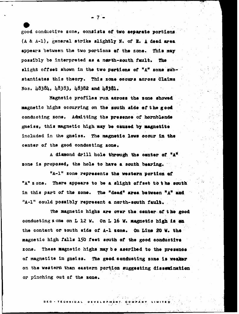
good conductive zone, consists of two separate portions
(A fc A-l), general strike slightly N. of 1. A dead area
appears between the two portions of the zone. Phis nay
possibly be interpreted as a north-south fault. The
slight offset shown in the two portions of "A" zone sub
stantiates this theory. This zone occurs across Claims
Noa. 48384, 48383, 48382 and 48381.
Magnetic profiles run across the 9000 showed
magnetic highs occurring on the south side of the good
conducting zone* Admitting the presence of hornblende
gneiss* this magnetic high may be caused by magnetite
included in the gneiss. The magnetic lows occur In the
center of the good conducting zone.
A diamond drill hole through the center of "A"
zone is proposed* the hole to have a south bearing*
11 A-l" zone represents the western portion of
"A" z one. There appears to be a slight offset to t he south
in this part of the zone. The "dead" area between "A* and
"A-l" could possibly represent a north-south fault*
The magnetic highs are over the center of too good
conducting zone on L 12 W. On L 16 W. magnetic high is on
the contact or louth side of A-l zone* On Lino 20 W. the
magnetic high falls 150 feet south of the good conductive
zone. These magnetic highs maybe ascribed to the presence
of magnetite in gneiss. The good conducting zone is weaker
on the western than eastern portion suggesting dissemination
or pinching out of the zone. , *
BED -TECHNICAL DEVELOPMENT COMPANY LIMITED
O -8-
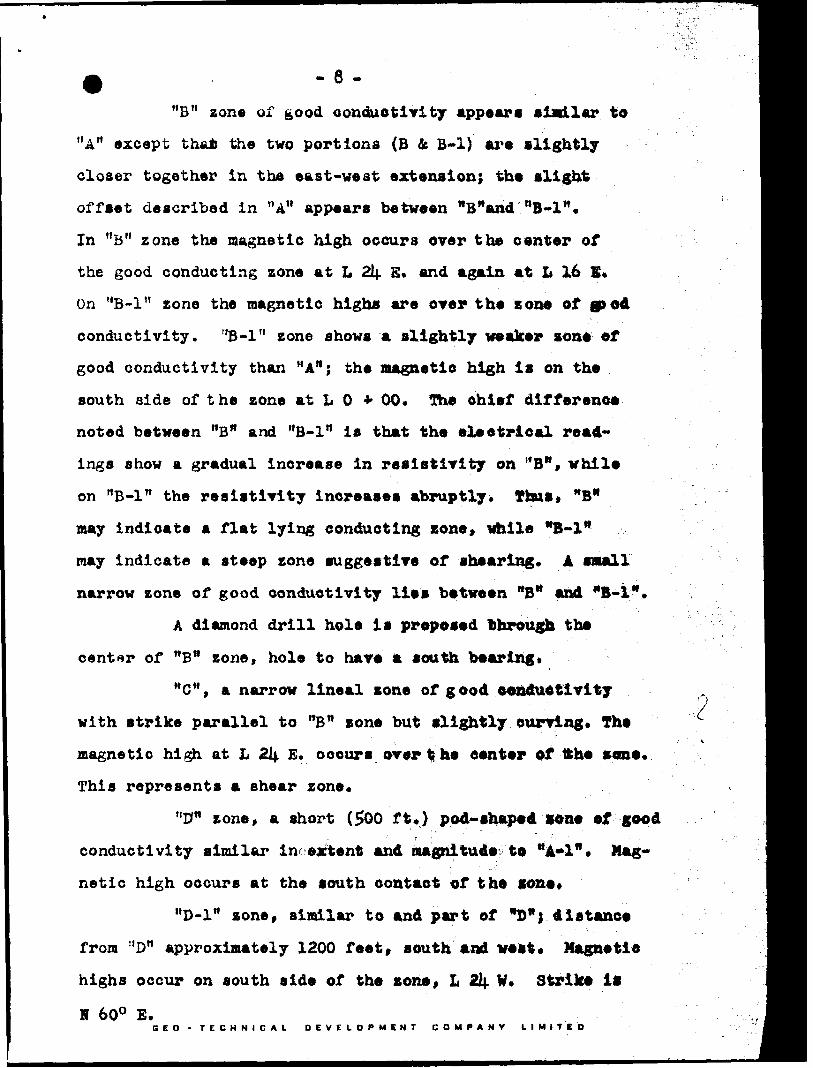
"B" zone of good conductivity appear* similar to
"A" except thai the two portions (B k B-l) are slightly
closer together in tha east-west extension; the alight
offset described in "A" appears between "B"and"B-1M .
In "B" zone the magnetic high occurs over the center of
the good conducting zone at L 2lj. E. and again at I* 16 5*
On "B-l" zone the magnetic highs are over the zone of 9 od
conductivity. "B-l" zone shows a slightly weaker son* of
good conductivity than "A"; the magnetic high is on the
south side of the zone at L O * 00. The chief difference
noted between "B" and "B-l" is that the eleetrical read
ings show a gradual increase in resistivity on HB", while
on "B-l" the resistivity increases abruptly. Thus* "B"
may indicate a flat lying conducting zone* while *B-1*
may indicate a steep zone suggestive of shearing. A small
narrow zone of good conductivity Iles between "B" and "B-l".
A diamond drill hole is proposed through the
center of "Bn zone, hole to have a south bearing.
"C", a narrow lineal sone of good conductivity
with strike parallel to "B" zone but slightly curving. The
magnetic high at L 21^ E. occurs over t he center of tfche sone.
This represents a shear zone.
"0" zone, a short (500 ft*) pod-shap*d cone of good
conductivity similar In extent and magnitude to "A*!". Mag
netic high occurs at the south contact of the zone*
"D-l" zone, similar to and part of "D"j distance
from "D" approximately 1200 feet, south and west. Magnetic
highs occur on south side of th* zone, L 2i|. W. Strike It
2
H 600 E.BED -TECHNICAL DEVELOPMENT COMPANY LIMITED
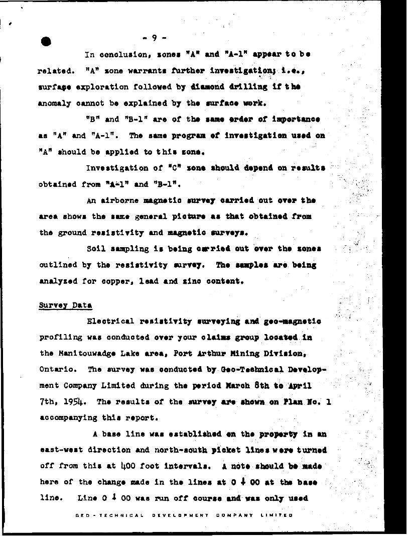
In conclusion, zonei "A" and "A-l" appear to b*
related. "A" cone warrants further investigation) i,e*,
surface exploration followed by diamond drilling if the
anomaly cannot be explained by the surface work.
"B" and "B-l" are of the sane order of importance
as "A" and HA-ln . The same program of investigation used on
"A" should be applied to this cone.
Investigation of "C" xono should d9pend on result*
obtained from "A-l" and "B-l".
An airborne magnetic survey carried out over the
area shows the same general picture as that obtained from
the ground resistivity and magnetic surveys.
Soil sampling is being carried out over the cones
outlined by the resistivity survey. The samples are being
analyzed for copper* lead and zinc content*
Survey Data
Electrical resistivity surveying and geo-magnetio
profiling was conducted over your claims group located in
the Manitouwadge Lake area. Port Arthur Mining Division*
Ontario. The survey was oonducted by (too-Technical Develop
ment Company Limited during the period March 8th to April
?th, 195^. The results of the survey are shown on Plan Ho. l
accompanying this report.
A base line was established ea the property in an
east-west direction and north-south picket lines were turned
off from this at 1;00 foot intervals. A note should be made
here of the change made in the lines at O 4 00 at the base
line. Line O -t 00 was run off course and was only used
GEO -TECHNICAL DEVELOPMENT COMPANY LIMITED

- 10 -
r a distance of 600 feet H* A new line was turned off at
0480 W. and run. This line was surveyed and is shewn on toe
accompanying map* The field pickets are marked "S.P," li th
ohalnage north or south of the base line. The line is
plainly marked in the field.
The electrical resistivity readings were taken at
50 foot Intervals along the picket lines* These readings
are depicted on Plan No. l to the east of the picket lines,
plotted in ohm-centimeters x 10\ and shown by contour lines*
The magnetic readings were taken at 100 foot inter
vals over and in the neighborhood of the good conducting
zones outlined by the resistivity survey. These readings
are plotted on Plan No. l to the west of the picket lines,
expressed in gammas and shown by profile lines*
A total of 9.i| miles of line were surveyed by the
electrical resistivity method, and 2.6 miles covered by the
magnetic survey.
The number of eight-hour sum-days required to
complete this work is as follows; J
Line cutting and chaining ,1(.5 x i*. Laying spread wire i x ij. Operating Resistivity Survey 2a x Operating Magnetic Survey .5 z Calculation A Interpretation q. x Drafting 7*4 Office typing 3c Supervision 12 x
102
•hour) Attributable to Man gays Assessment Work
1602096201628its uos
May 3, 1951* Toronto, Ontario
Respectfully submitted, QEO-TECHHICAL DSVILOPMKIT COHTHI LTD.
f fE. P. Sheppard Geologist
BED -TECHNICAL DEVELOPMENT COMPANY LIMITED

SOIL SAMPLE DATA of SUDBURY C OH T AC T HUES LIMITSD, itouwadge Lake Area, Ontario*
alyses made by testing with colorimetric method using"dlthizone")
Field Samples secured April 8-13, 1954* Assay Reports dated April 26 and May 7, 1954*
Sample Ho.
A 1 A 2A 3A kA 5A 6A 7A 8A 9
55565758596061626361^656667
Lab. No.
1 23
\6789
8151815281538151*815581568157815881598160816181628163
Parts per million
Copper
10 1191051051331U7U910V?
U545223560604522
5̂0602010
Lead
10 2010101010101520
701*030203000
40200202520
Zino
30it4540l060600
(**So
475254540
.Mjttlo*..
Line He.
2,,,tt
*"* : '* '
0400aN
SBwB' n .'.y" -
' ". . - ••n'
12Swtt ' - .tt ' -tt
161wtt
Footage o'-"
1950*1 1556*11200*1950*1700*1500*1100 'H356*1600*1
1700*8iSOO.fg1900 'S2050 *S2100*S2300 's2000*81900*31600*31700*81600*81700*81050*8
GEO TECHNICAL DEVELOPMENT COMPANY LIMITED

48407
48406
J- "J
48408 48411 48404
48410
48403
48409
48384
OR AN rvi
GNEISS (ALTERU)
RESISTIVITY ANOMALY
SWAMP, ALtUK SPRUC
GLACIAL TILL, hlRCM
G EO LO GY
SUDBURY CONTACT MINES LTD
MANITOUWADGE AREA,
LOCATION MAP l"* l MILE
fiA?**^, r42FMNWM3* 83.461 MANITOUWADQE UAKE

oo
100
200
UP
o ui
L li G E H D
LINES CUT AND CHAINED, RFSISTIVITV IUADINGS OBSERVED
HI. j 1ST l VITY CONTOUR
MAGNETIC READINGS PLOTTED ON WEST S l D F.
O c i
AND MAGNETIC PROFILES PLOTTED TO SCALF.
ELECTRICAL RESISTIVITY ANOMALY
FAULT ZONE INFERRED FROM GEOPHYSICAL SURVEY
PROPOSED DRILL HOLES
OUTLINE OF HIGH GROUND
OUTCROP
LOCATION OF SOIL SPECIMEN SAMPLE
OF LINE GRID l - IOOO i/-
Cu
LOCATION OF SOIL SAMPLE C ANALYSIS INDICAIfcS O~{ C* )
CLAIM BOUNDARY AND LLAIM POST LO'.A'IUD
LOCATION MAPSCALE l - l MILE
ELECTRICAL RESISTIVITY SURVEY OVER PROPERTY OF
SUDBURY CONTACT MINES LIMITEDRESISTIVITY CONTOURS AND GEOLOGICAL INTERPRETATION
AND IN PART MAGNETIC PROFILES
M ANITOUWADGL LAKt ARtANAMA CRLLK bEC I ION
DlbrUlCT OF THUNDtR BAY POH l Af^lHUR MIMING DIVISION
ON T A R l O
GEOPHYSICAL SURVEY BY
CEO-TECHNICAL DEVELOPMENT COMPANY LIMITEDPLAN NO l MARCH 1954
SCALE (400'
63 4bl HANITOUWADQE UAKE aio4(00* ~t - 00*
JU 0-4 -54