Detailing procedures for seismic rehabilitation of … procedures for seismic rehabilitation of...
12
Engineering Structures 30 (2008) 450–461 www.elsevier.com/locate/engstruct Detailing procedures for seismic rehabilitation of reinforced concrete members with fiber reinforced polymers S.P. Tastani * , S.J. Pantazopoulou Demokritus University of Thrace (DUTh), Vas. Sofias Street No. 1, Xanthi 67100, Greece Received 9 August 2005; received in revised form 31 January 2007; accepted 22 March 2007 Available online 25 May 2007 Abstract Fiber reinforced polymer jackets (FRP sheets) offer great advantages as confining devices of damaged or substandard reinforced concrete (r.c.) members and are already used extensively as local interventions in seismic rehabilitation of existing construction. The design issues and detailing rules related to this seismic repair/strengthening technique are explored by evaluating systematically the various mechanisms of resistance of the upgraded member and the jacket contribution. These include flexure, shear, lap-splice capacity, plastic hinge behavior, displacement capacity and jacket strain capacity associated with embedded bar buckling. A database of published experiments on r.c. beam/columns, tested under cyclic loading after being jacketed by FRPs was used as a point of reference in assessing the detailing rules and in calibrating design lower bound expressions. Criteria that should be considered for the upgrade design strategy in order to control the deformation demand of the structure when FRP jackets are used are also discussed in the paper. c 2007 Elsevier Ltd. All rights reserved. Keywords: FRP jacketing; Repair; Strengthening; Seismic upgrading; Design 1. Introduction A basic ailment of many of the r.c. structures that get damaged during earthquakes is intrinsic lack of stiffness (e.g. in soft storey formations), combined with limited deformation capacity of the individual structural elements owing to non- ductile, old type detailing. Because excessive displacement brings out all the potential problems of an inadequate design or construction, it is necessary in repair/strengthening schemes to target for reduced displacement demand, by increasing the lateral stiffness of the structure. The necessary global interventions are accompanied by targeted local measures aiming to increase the dependable deformation capacity of the individual members so that the supply exceeds the deformation demand. Rehabilitation of damaged or under-designed r.c. beam and columns with FRP jacketing belongs to the class of local interventions. In the context of this paper, the expression FRP * Corresponding author. Tel.: +30 25410 79639; fax: +30 25410 79639. E-mail addresses: [email protected] (S.P. Tastani), [email protected] (S.J. Pantazopoulou). jacketing refers to any type of application of the material where the primary fibers are oriented transversally to the longitudinal axis of the upgraded member and at a minimum of three faces of the member’s cross section so as to facilitate confining action against any dilation of the concrete (i.e. due to axial load, shear transverse tension or dilation produced by the bond action of a ribbed bar). Although FRP jackets are effective in upgrading shear strength, lap splice strength, and overall flexural and shear deformation capacity, they combine three characteristics that may prevail and control failure in a flexible structure. Thus, (a) they have negligible influence on the lateral stiffness of the jacketed member. Unless the transverse jackets serve to mitigate premature local failures that would otherwise limit the pre-yield response, secant to yield stiffness (EI ) remains unaltered by the repair. (b) They are susceptible to rupture at points of localized deformation demand. Although they can substantially increase the compression strain capacity of encased concrete, they delay but cannot preclude eventual buckling of compression reinforcement and the ensuing collapse of the member. (c) They effectively reduce shear cracking in the plastic hinge regions, driving all deformation to occur within a few flexural cracks 0141-0296/$ - see front matter c 2007 Elsevier Ltd. All rights reserved. doi:10.1016/j.engstruct.2007.03.028
Transcript of Detailing procedures for seismic rehabilitation of … procedures for seismic rehabilitation of...
Engineering Structures 30 (2008) 450–461www.elsevier.com/locate/engstruct
Detailing procedures for seismic rehabilitation of reinforced concretemembers with fiber reinforced polymers
S.P. Tastani∗, S.J. Pantazopoulou
Demokritus University of Thrace (DUTh), Vas. Sofias Street No. 1, Xanthi 67100, Greece
Received 9 August 2005; received in revised form 31 January 2007; accepted 22 March 2007Available online 25 May 2007
Abstract
Fiber reinforced polymer jackets (FRP sheets) offer great advantages as confining devices of damaged or substandard reinforced concrete (r.c.)members and are already used extensively as local interventions in seismic rehabilitation of existing construction. The design issues and detailingrules related to this seismic repair/strengthening technique are explored by evaluating systematically the various mechanisms of resistance of theupgraded member and the jacket contribution. These include flexure, shear, lap-splice capacity, plastic hinge behavior, displacement capacity andjacket strain capacity associated with embedded bar buckling. A database of published experiments on r.c. beam/columns, tested under cyclicloading after being jacketed by FRPs was used as a point of reference in assessing the detailing rules and in calibrating design lower boundexpressions. Criteria that should be considered for the upgrade design strategy in order to control the deformation demand of the structure whenFRP jackets are used are also discussed in the paper.c© 2007 Elsevier Ltd. All rights reserved.
Keywords: FRP jacketing; Repair; Strengthening; Seismic upgrading; Design
1. Introduction
A basic ailment of many of the r.c. structures that getdamaged during earthquakes is intrinsic lack of stiffness (e.g. insoft storey formations), combined with limited deformationcapacity of the individual structural elements owing to non-ductile, old type detailing. Because excessive displacementbrings out all the potential problems of an inadequate designor construction, it is necessary in repair/strengthening schemesto target for reduced displacement demand, by increasingthe lateral stiffness of the structure. The necessary globalinterventions are accompanied by targeted local measuresaiming to increase the dependable deformation capacity of theindividual members so that the supply exceeds the deformationdemand.
Rehabilitation of damaged or under-designed r.c. beam andcolumns with FRP jacketing belongs to the class of localinterventions. In the context of this paper, the expression FRP
∗ Corresponding author. Tel.: +30 25410 79639; fax: +30 25410 79639.E-mail addresses: [email protected] (S.P. Tastani),
[email protected] (S.J. Pantazopoulou).
0141-0296/$ - see front matter c© 2007 Elsevier Ltd. All rights reserved.doi:10.1016/j.engstruct.2007.03.028
jacketing refers to any type of application of the materialwhere the primary fibers are oriented transversally to thelongitudinal axis of the upgraded member and at a minimumof three faces of the member’s cross section so as to facilitateconfining action against any dilation of the concrete (i.e. dueto axial load, shear transverse tension or dilation producedby the bond action of a ribbed bar). Although FRP jacketsare effective in upgrading shear strength, lap splice strength,and overall flexural and shear deformation capacity, theycombine three characteristics that may prevail and controlfailure in a flexible structure. Thus, (a) they have negligibleinfluence on the lateral stiffness of the jacketed member.Unless the transverse jackets serve to mitigate premature localfailures that would otherwise limit the pre-yield response,secant to yield stiffness (EI) remains unaltered by the repair.(b) They are susceptible to rupture at points of localizeddeformation demand. Although they can substantially increasethe compression strain capacity of encased concrete, theydelay but cannot preclude eventual buckling of compressionreinforcement and the ensuing collapse of the member. (c) Theyeffectively reduce shear cracking in the plastic hinge regions,driving all deformation to occur within a few flexural cracks
S.P. Tastani, S.J. Pantazopoulou / Engineering Structures 30 (2008) 450–461 451
Nomenclature
Ast cross-sectional area of stirrup legs in a singlestirrup layer (mm2).
Ag cross-sectional area of r.c. member (mm2).b cross-sectional width (mm).c clear cover of steel reinforcement (mm).d cross-sectional effective depth (mm).Db longitudinal bar diameter (mm).E f modulus of elasticity of the FRP (GPa).fb average bond stress (MPa).f ′c , f ′
t uniaxial compressive and tensile strength ofconcrete (MPa).
f ′cc confined compressive strength of concrete (MPa).
f f b, f f b,d average bond stress and design value of theFRP sheet (MPa).
f f u nominal rupture stress of FRP material (MPa).fgl,d design shear strength of the resin (MPa).fs,crit critical buckling stress of compression reinforce-
ment (MPa).fy , fy,st yield stress of longitudinal and transverse
reinforcement (MPa).h cross-sectional height (mm).k f , kst effectiveness coefficients of FRP jacket and
stirrups. Superscript v refers to the sheareffectiveness, anch to the anchorage effectivenessand c to confinement effectiveness.
Lb, L f development length of longitudinal bar and FRPply, respectively (mm).
lp plastic hinge length (mm).Ls shear span of the r.c. member (mm).n number of FRP layers.Nb number of longitudinal bars.P axial load on the cross section (in N).q or R behavior factor.s spacing of stirrups (mm).sgl,u slip of the resin (mm).t f FRP ply thickness (mm).wcr crack width (mm).∆y,∆u yielding and ultimate displacement (mm).εc,u , εcc,u failure strain of unconfined and confined
concrete.εco, εcc uniaxial compressive strain at f ′
c and at f ′cc.
εe f ff effective tensile strain of the FRP jacket.
ε f u,d nominal deformation capacity of the FRPmaterial.
εs,crit critical buckling strain of compression reinforce-ment.
εs,cu strain of the compression reinforcement corre-sponding to εcc,u .
εy yield strain of longitudinal reinforcement.φy/φu yielding and ultimate curvature (1/mm)γ f b material safety factor for the relationship between
characteristic and design bond strengthµ coefficient of friction at the steel–concrete
interface.
µ∆,µφ, µε displacement, curvature and compressionstrain ductility.
ρ f v , ρsv volumetric ratio of FRP jacket and stirrups.ρ f y , ρsy transverse FRP and steel ratio.σlat passive pressure; superscripts f and st refer to
pressures applied by FRP and stirrups (MPa).
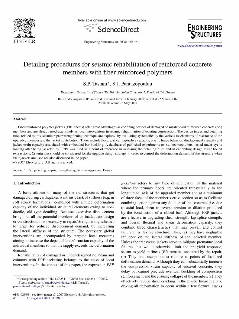
Fig. 1. Improvement of response due to FRP jacketing—definition ofdeformation indices.
near the face of the support. Confinement enables attainmentof high strain demands in the tension reinforcement at thecritical section. The increased demand for bar developmentcapacity cannot always be met by the anchorage which isoften inadequate in substandard construction and inaccessibleto rehabilitation (Tastani and Pantazopoulou [1]).
As a local intervention, FRP jacketing needs be explicitlyembedded in the context of the integrated global strategy ofseismic rehabilitation of the structure, where, survivability ofthe upgraded structural system depends on the magnitude ofthe lateral drift. In the paper, the first sections consider theconfining pressure generated by the FRP, its effectiveness, andthe design effective strain that may be used in calculations.The derived expressions are used next to obtain the variousstrength terms and the deformation capacity of FRP jacketedr.c. members. Considerations about drift control that need becombined with the FRP jacketing are discussed and the entireprocedure is applied in a building case study using the YieldPoint Spectrum Method to guide the upgrading strategy.
2. Mechanical effects of FRP jacketing on r.c. members
In selecting FRP jacketing for seismic upgrading, the repairobjective is restricted to maintaining or marginally increasingthe flexural strength of the members without influencingtheir initial stiffness (Fig. 1), up to full exploitation of thedeformation capacity of longitudinal reinforcement. The actualincrease in strength and deformation capacity effected throughFRP jacketing may be quantified by approaches similar tothose used in the case of conventionally r.c. members. ACI440.2R-02 [2] presents expressions for calculation of strengthenhancement and design recommendations.
As with stirrups, the jacket is mobilized in tensionwhen the encased concrete dilates laterally. Lateral expansion(resembling Poisson’s effect in elastic media) occurs inconcrete when the material is under significant axialcompressive stress. The FRP jacket acts as passive confinement
452 S.P. Tastani, S.J. Pantazopoulou / Engineering Structures 30 (2008) 450–461
by restraining dilation, thereby enhancing the deformationcapacity of confined concrete (Pantazopoulou [3]). In r.c.members with sparse stirrups the poorly supported longitudinalcompression reinforcement tends to buckle outwards at largecompression strains. In these cases the FRP jacket resistsstress concentrations along the buckling rebars. Web dilationalso occurs in the presence of significant shear action (webcracking due to diagonal tension failure of concrete). In thiscase the FRP jacket functions as the tension tie in a strut-and-tie analog of the shear resisting mechanism of the concretemember. FRP wrapping over the embedment length of baranchorages provides clamping, resisting propagation of coversplitting thereby enhancing the frictional mechanism of bondresistance.
Depending on the function of the jacket in the rehabilitationscheme, either the transverse pressure in the x or y direction(σlat,x , σlat,y), or the average pressure in two orthogonaldirections σ ave
lat = 0.5(σlat,x + σlat,y) may be needed to quantifythe mechanical function of pressure on resistance. In anygiven direction of action y, the total transverse pressure, σlat,y ,comprises contributions of the FRP jacket and the occasionalembedded stirrups:
σlat,y = σf
lat,y + σ stlat,y = 2
k f,ynt f E f εefff
b+
kst,y Ast fy,st
sb. (1)
Parameters k f,y and kst,y are the effectiveness coefficientsfor the two transverse confining systems in the direction ofinterest y (i.e. intersecting the plane of failure), εeff
f is theeffective tensile strain that develops in the jacket near failure(which may occur either by debonding or by rupture, whicheverprevails), E f , n, t f are the elastic modulus, the number of pliesand the thickness of an FRP ply, b is the cross-section width atthe splitting plane (orthogonal to the applied jacket force), Ast isthe total cross-sectional area of stirrup legs crossing the splittingplane provided by a single stirrup layer, s the longitudinalspacing of stirrups and fy,st their yield stress.
2.1. Effectiveness coefficients for the various response mecha-nisms
The effectiveness coefficients k f,y and kst,y in (1) for the twotransverse reinforcement systems depend upon the function ofσlat,y in the response mechanism considered:
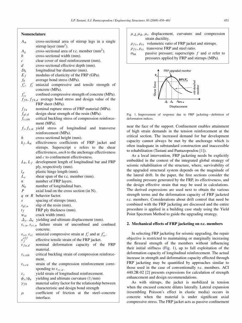
For shear strengthening, k f,y depends on the developmentcapacity of the jacket anchorage, whereas kst,y = 1 for wellanchored closed stirrups. Consider a shear crack extending at45◦ along the web height d f (Fig. 2(a)); transverse pressuredevelops in the y direction (along the web height). The wrappedjacket is called on to develop its design strain at the criticalsection, which is at the point of intersection with the crack. Ifthe jacket is closed (i.e., four-sided, well anchored application),then k f,y = 1 (Fig. 2(b)). If, owing to the cross-sectionalshape of the member it is not possible to wrap the jacketaround the section, thus terminating it on the web near thecompression zone, (e.g. near the underside of the flange in T-beams, Fig. 2(a)), then, only those fibers that have sufficientanchorage length L f beyond the crack may be considered
Fig. 2. (a) Free body diagram of FRP wrapped member at a shear crack planeand (b) stress state of FRP strengthened rectangular cross section.
effective as shear reinforcement (here the presence of possiblemechanical anchorage means is not considered). In this case,the effectiveness coefficient is k f,y = (d f − L f )/d f < 1; indirect analogy, for open shear links, kst,y = 0.5 (FIB Bulletin24 [4]). ACI 440.2R-02 [2] proposes methods for calculatingL f (this is also discussed in the following sections).
When strengthening for confinement, the confining pressureis the average value σ ave
lat obtained from (1) in the two principaldirections of the cross section as σlat-x and σlat-y :
σ avelat = 0.5
(σlat,y + σlat,x
)= 0.5
(kc
f ρ f v E f εefff + kc
stρsv fy,st
)(2)
where, ρ f v = 2nt f (b + h)/(bh) and ρsv = (b + h)Ast/(bhs)are the volumetric ratios of FRP and stirrup reinforcement(h is the cross-section height). The expression for calculatingkc
f approximates the volume fraction of core concrete that iseffectively restrained (similar to the approach used to evaluateconfinement effectiveness of stirrups kc
st (Priestley et al. [5]).Therefore, kc
f = 1 − (b′2+ d ′2)/[3Ag(1 − ρs)], where Ag
is the gross cross section of the element, ρs is the ratio oflongitudinal reinforcement, and b′ and d ′ the straight sidesof the rectangular cross section encased by the jacket afterchamfering the corners (ACI 440.2R-02 [2], FIB Bulletin14 [6]). Thus, for a cross section with a side aspect ratio of3, the confinement effectiveness coefficient becomes negligible(kc
f ≈ 0), whereas for square and circular cross sections kcf ≈
0.5 and 1, respectively. Therefore, the primary function of FRPwrapping in a cross section with a very large aspect ratio wouldbe to increase its lateral load resistance rather than its axial loadstrength (i.e., in these cases any reference to strength increaseowing to confinement may be neglected).
When strengthening bar anchorages or lap splices throughtransverse restraint the effectiveness coefficients kanch
f,y , kanchst,y
take into account how uniform is the restraint provided thoughthe FRP jacket or the stirrups: for the continuous FRP jacketkanch
f,y = 1 whereas kanchst,y ≈ 0.33 for stirrups to account for their
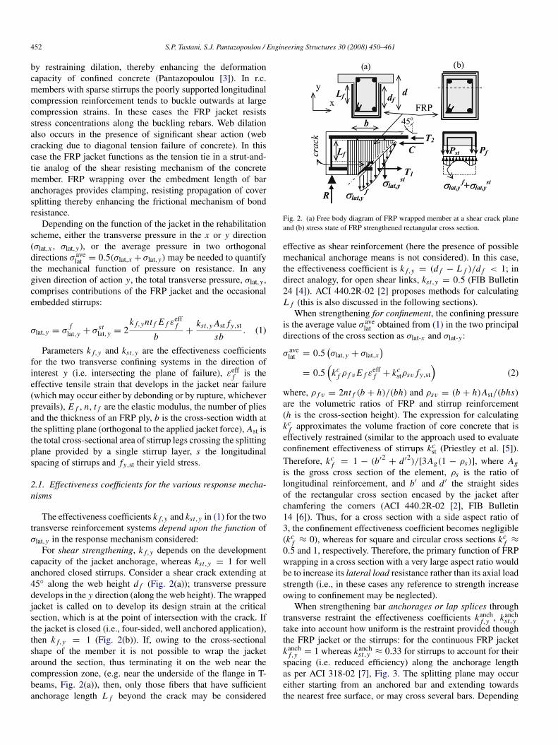
spacing (i.e. reduced efficiency) along the anchorage lengthas per ACI 318-02 [7], Fig. 3. The splitting plane may occureither starting from an anchored bar and extending towardsthe nearest free surface, or may cross several bars. Depending
S.P. Tastani, S.J. Pantazopoulou / Engineering Structures 30 (2008) 450–461 453
Fig. 3. Definition of the effectiveness coefficient of stirrups kanchst for anchorage
restraint: kanchst averages stirrup stress along their spacing s.
on the direction of splitting, the restraining pressure (and theassociated terms in (1)) may be in either of the two principaldirections of the cross section.
2.1.1. Derivation of the effective strain, εefff
The effective strain εefff in (1) and (2) is the usable tensile
strain capacity of the FRP jacket. In general, εefff is only a
fraction of the nominal deformation capacity of the material(ε f u,d ). The value of εeff
f depends on the mode of failure ofthe bonded layer that in turn is controlled by the bond strengthof the substrate. Choosing a reliable value for εeff
f is a criticalstep in establishing the contribution of jacket stresses to anyfailure mechanism of concrete. In the following, εeff
f is defineddepending on the jacket geometry (open or closed) and thelikely mode of failure of the wrap.
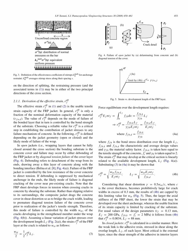
In open jackets (i.e., wrapping layers that cannot be fullyclosed around the cross section) the bonding substrate is theconcrete cover and failure may occur by either debonding ofthe FRP jacket or by diagonal tension failure of the cover layer(Fig. 4). Debonding refers to detachment of the wrap from itsends, drawing away a thin layer of concrete along with thebonding interface (Brena et al. [8], Fig. 4(a)). Failure of the FRPjacket is controlled by the low resistance of the cover concreteto direct tension. If debonding is suppressed by mechanicalanchorage in the ends, the likely mode of failure is diagonalcracking of the cover near pre-existing cracks. Note that theFRP sheet develops forces in tension when crossing cracks inconcrete by shearing the substrate. Rather than slipping relativeto its surroundings, the composite jacket drags the concretecover in shear distortion so as to bridge the crack width, leadingto premature diagonal tension failure of the concrete coverprior to realization of the jacket’s tensile strength. Therefore,this mode of failure is controlled by the width wcr, of thecracks developing in the strengthened member under the wrap(Fig. 4(b)). Assuming a linear variation of jacket stresses overthe development length L f (Fig. 2(a)), the strain εeff
f of the FRPlayer at the crack is related to wcr as follows:
wcr
2=
12εeff
f L f . (3)
Fig. 4. Failure of open jacket by (a) delaminating from concrete and (b)diagonal tension of the cover.
Fig. 5. Strain vs. development length of the FRP layer.
Force equilibrium over the development length requires:
εefff E f nt f =
∫ L f
0f f bdx =
f f b,k
γ f bL f
⇒ εefff =
f f b,k L f
γ f b E f nt f=
f f b,d L f
E f nt f;
where f f b,d =f f b,k
γ f b(4a)
where f f b is the bond stress distribution over the length L f ,f f b,k and f f b,d the characteristic and average design valuesand γ f b the material safety factor. f f b,k is taken here equal tothe tensile strength of the concrete, f ′
t and γb is taken equal to 2.The strain εeff
f that may develop at the critical section is linearlyrelated to the available development length, L f (Fig. 4(a)).Substituting (3) in (4a) it may be shown that
εefff =
√wcr f f b,d
E f nt f; L f =
√wcr E f nt f
f f b,d. (4b)
Considering that shear distortion γ = 0.5wcr/c, where cis the cover thickness, becomes prohibitively large for crackwidths in excess of 0.3 mm, the results of (4b) are capped bythis limiting value for wcr (Fig. 5). Thus, the larger the axialstiffness of the FRP sheet, the lower the strain that may bedeveloped over the sheet anchorage, whereas the usable fractionof its strain capacity is limited by cracking of the substrate.For usual values of the design parameters (t f = 0.13 mm,E f = 200 GPa, f f b,k = f ′
t = 2 MPa) it follows from (4b)that εeff
f = 0.0034, L f = 88 mm.
In closed jackets: εefff is calculated in a similar manner. Here
the weak link is the adhesive resin, stressed in shear along theoverlap length, L f , of each layer. Most critical is the externallayer, since the shear strength of the adhesive in interior layers

454 S.P. Tastani, S.J. Pantazopoulou / Engineering Structures 30 (2008) 450–461
is enhanced by friction due to confinement. The strength of thebonded system is controlled by the limiting slip sgl,u of theadhesive at shear failure:
su,gl = εefff L f
εefff E f t f = fgl,d L f
}⇒ εeff
f =
√fgl,dsu,gl
E f t f;
L f =
√su,gl E f t f
fgl,d(4c)
where fgl,d is the shear strength of the adhesive at the stage ofplastification. For illustrative purposes consider the followingexample: fgl,d = 5 MPa, su,gl = 1 mm, E f = 200 GPa,and t f = 0.13 mm, barring any stress concentrations thatwould accelerate jacket failure, it follows that εeff
f = 0.0138,and L f = 72 mm. Clearly the input data to this calculationdepend on the adhesive properties; a very large range ofproducts is available and used in FRP applications. Thus, adetailed study of FRP lap-splice development capacities wouldbe needed before design values may be proposed for practicalapplications.
According to ACI 440.2R-02 [2] the allowable values forεeff
f under monotonic loads are 0.004 and 0.75ε f u,d for openand closed jackets, respectively. Results from compression testswith closed FRP jackets (Chaallal et al. [9]) indicate that thematerial factor of 0.75 is rather high when used with rectangularcross sections due to the jacket’s susceptibility to local ruptureat the corners even after chamfering. A value of 0.5 has beenfound more conservative in this case (i.e., εeff
f = 0.5ε f u,d ,Tastani and Pantazopoulou [1]).
3. Strength assessment of FRP rehabilitated r.c. members
In redesigning a substandard r.c. element for seismicresistance the objective is to mitigate all failure modes exceptflexural, which is the most desirable. Design forces must satisfythe following qualitative relationship:
Vu,lim = min{Viflex, Vshear, Vanch, Vbuckl} (5)
where, Viflex = Mu/Ls is the seismic shear force required todevelop the ideal flexural resistance of the member, Ls is theshear span, Vshear is the nominal shear resistance, Vanch is themember shear force when the anchorage/lap-splice reach theirdevelopment capacity and Vbuckl is the member shear forcewhen compression reinforcement reaches buckling conditionsat the critical section. The strength components in (5) may beestimated from variables σlat,x , σlat,yand σ ave
lat , calculated by (1)and (2). The necessary calculation steps are presented below.
3.1. Ideal flexural capacity calculations
Flexural resistance is influenced by the concrete strengthincrease owing to confinement, and the containment of thecover region that would otherwise have spalled-off at ultimate.The confined concrete strength f ′
cc and the corresponding strainat attainment of peak stress, εcc, in the compression zone
of the encased cross section is calculated from the classicalconfinement model of Richart et al. [10]:
f ′cc = f ′
c + 4.1σ avelat ; εcc = εco
(1 + 5
(f ′cc
f ′c
− 1))
. (6)
Experimental results from FRP-confined concrete cylinderspoint to a reduced effect of transverse pressure on confinedcompressive strength (Tastani et al. [11], a multiplier of 3 ratherthan 4.1 operating on σ ave
lat ). By substitution of (2) in (6), andassuming εco = 0.002 (strain at peak stress of unconfinedconcrete), the following are obtained:
f ′cc = f ′
c + 1.5(
kcf ρ f v E f ε
efff + kc
stρsv fy,st
)εcc = 0.002 + 0.015
kcf ρ f v E f ε
efff + kc
stρsv fy,st
f ′c
. (7)
The failure strain εcc,u corresponding to a compressionstrength reduction in excess of 15% is obtained from twoalternative expressions:
(a) Priestley et al. [5] have proposed:
εcc,u = 0.004 + 1.25kc
f ρ f v E f (εefff )2
f ′cc
. (8a)
(b) A lower bound expression has been calibrated with testresults (Pantazopoulou [3]):
εcc,u = εc,u + 0.075
×
(kc
f ρ f v E f εefff + kc
stρsv fy,st
f ′c
− 0.1
)> εc,u;
0.003 6 εc,u 6 0.004. (8b)
For closed jackets, εefff = 0.5ε f u,d . Note that being a lower
bound, (8b) is rather conservative.
3.2. Shear strength calculations
Shear resistance of r.c. members subjected to displacementreversals degrades with the number of cycles and the magnitudeof imposed displacement ductility, owing to breakdown ofconcrete’s tensile and compressive resistance with increasingcrack widths. This strength reduction is accounted for using aductility dependent softening coefficient λ (Moehle et al. [12])as:
Vn(µ∆) = λ (Vs + Vc) ; λ = 1.15 − 0.075µ∆; 0.7 6 λ 6 1
Vs = σ stlatbd
Moehle et al. [12] : Vc =6√
f ′c
a/d
√1 +
P
6√
f ′c · Ag
· Ag
( f ′c in psi) (9)
EKOS-2000 : Vc = β ·
[τRdk (1.2 + 40ρl) + 0.15
P
Ag
]· bd(N ).
In the expression for Vc given by Moehle et al. [12] Pis the axial load on the section, α is the distance from
S.P. Tastani, S.J. Pantazopoulou / Engineering Structures 30 (2008) 450–461 455
maximum moment to inflection point. In the Greek DesignCode (EKOS-2000, [13]) parameter β takes into account thetype of r.c. member (plate/shell or linear) in combination withthe magnitude of axial load (i.e. β = 0.3 for seismic designof column and beam where the axial load is P 6 0.1bh f ′
c ,0.9 for higher axial loads), τRd is the shear strength of plainconcrete (=0.25 f ′
t ), k is a size-effect factor (=1.6 − d > 1, din m) and ρl is the ratio of longitudinal reinforcement that actsas dowels. Factor µ∆ is the imposed displacement ductility.Parameter Ag is the cross section area of the r.c. member.The transverse pressure σ st
lat,y contributed by any dependablestirrups is calculated from the second term of (1). In redesigningsubstandard r.c. members for shear resistance, (9) needs to beused both in assessing the residual Vn-res prior to the FRPjacketing intervention and also in evaluating the post-upgradingresistance. Therefore:
Vn-res(qold) = λ(qold) (Vs + Vc)
Vn(qnew) = min {λ(qold), λ(qnew)} (Vs + Vc) + V fw ;
V fw = σ
flat,y Ag
(10)
where q is the behavior factor (or R in FEMA 273 [14])and σ
flat,y is the transverse pressure in concrete owing to the
jacket in the direction of lateral sway (first term of (1)).The shear strength of the jacketed member is the sum of thejacket contribution, V f
w , and the contribution of the existingmechanisms, namely concrete, Vc, and transverse steel, Vs .
In deriving (10), it has been assumed that the target µ∆
used in the redesign of the member is equal to the behaviorindex, qnew (or Rnew), thus, µ∆ ≤ 3.5–4 that is currentlyrecommended for new designs (FEMA 273 [14], EC-8 [15]).It is recognized in (10) that the existing mechanisms mayhave sustained damage during previous loading. For this reasonresidual rather than the full contributions of core concrete andweb reinforcement are considered, by taking the minimumvalue of λ for these terms, based on the ductility demandsuffered during previous events, or used as a target value forredesign. Based on experiments the softening coefficient λ isnot applied on the V f
w as diagonal cracking is suppressed bythe application of the jacket (Tastani and Pantazopoulou [1]).
3.3. Anchorage/lap-splice strength calculations
As a rule, a direct consequence of upgrading memberresistance through FRP jacketing is to increase the deformationdemand in the lap-splice/anchorage regions. Frequent bondrelated problems in existing construction include, (a) lapsplicing of the main bars immediately above the floor levelin the anticipated plastic hinge regions without the necessarytransverse reinforcement, (b) use of smooth reinforcementwhere bond capacity depends on the frictional resistance andthe formed end-hooks, and (c) use of short developmentlengths.
To remedy anchorage problems, FRP jackets are wrappedorthogonal to the anticipated splitting plane. Using the ACI318-02 [7] frictional model for the bond, the developmentcapacity of a given anchorage length Lb is calculated from:
F = 0.5π · Db · Lb · fb = µ · σlat · Db · Lb, where µ is thecoefficient of friction at the steel–concrete interface and σlat thepressure exerted upon the lateral surface of the bar by the cover,transverse stirrups and FRP jacket. The average bond stress fb,d
is given by,
fb,d =2µ
π Db
(σ c
lat +σ st
lat + σf
lat
Nb
)
=2µ
π Db
(ζ · c · f ′
t +kanch
st Ast fy,st
Nbs+
2kanchf nt f E f ε
efff
Nb
)(11)
where Nb is the number of bars (or pairs of spliced bars)laterally restrained by the transverse pressure. Note that σ
flat
and σ stlat are obtained from (1) when considering the likely
plane of splitting failure through the lap or anchorage—e.g. thecrack path to the nearest unrestrained surface and the pertinenteffectiveness coefficients for the anchorage; σ c
lat represents thetransverse confining pressure exerted by the concrete cover(ζ = 1, 2 either for fully elastic or fully plastic behavior of theconcrete cover). For lap splices the likely cover spalling path, p,which depends on the density of bar placement along the crosssectional perimeter would be used instead of c in (11) (Priestleyet al. [5]).
The value of εefff used in (11), is the surface strain value
associated with attainment of bond strength along the bar. Forconventional deformed bars bond strength is attained at a barslip of 0.1–0.2 mm (Tastani and Pantazopoulou [16]). Recentresults (Lura et al. [17]) show that at any point along the bar,slip is about twice the radial displacement of the internal barboundary imposed by the displacing ribs, thus, the associatedradial displacement at the bar surface is ur,o = 0.05–0.1 mm.The corresponding hoop strain equals the ur,o divided by theradius of the internal boundary, εho
= ur,o/(Db/2). If thechange in radial displacement occurring through the coverthickness owing to contraction of concrete is neglected, thenthe hoop strain at the outside boundary of the cover, wherethe FRP jacket is installed is: εeff
f = ur,o/(c + Db/2) =
2ur,o · [Db(1 + 2(c/Db))]−1
= εho· (1 + 2(c/Db))
−1. Forexample, for Db = 20 mm and c = Db, εho
= 0.005 − 0.01,and εeff
f = 0.0017−0.003, a range of values consistent with theempirical strain lower limit of 0.0015 that has been proposedfor calculating the jacket stress for lap splices and anchorages(Priestley et al. [5]). The lateral force in (5) required to developthe anchorage or lap splice capacity in the upgraded element isreferred to as Vanch = [π Db Lb fb,d Nb jd + P(d − 0.h)]/Ls
where jd is the lever arm between the internal reinforcementforce and concrete stress resultant and P is the applied axialforce.
Thus, particularly for anchorage and lap splice calculations,(11) should be used with the following values for stirrup andFRP-jacket stresses: min{200 GPa · 0.1/Db, fy,st} and E f ·
(εefff due to slip of the bar), respectively. If greater values are
used in (11) for the strains of stirrups and jacket, this should beaccompanied by attendant reductions in the value of the shear
456 S.P. Tastani, S.J. Pantazopoulou / Engineering Structures 30 (2008) 450–461
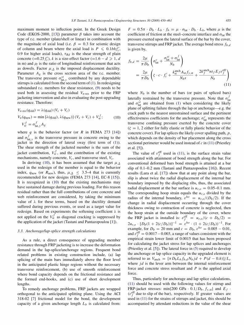
Fig. 6. Relationship between dependable compressive strain ductility, µεc ands/Db ratio.
friction coefficient µ so as to reflect the increased level of bonddamage.
3.4. Resistance to longitudinal bar buckling in FRP-wrappedr.c. elements
In r.c. members with substandard details, the compressionstrain capacity of longitudinal reinforcement is often limitedby premature buckling owing to the large unsupported lengthof the bars: stirrup spacing in the range of 200–300 mm isnot uncommon in old construction. At this spacing s, the barslenderness ratio s/Db is 10–15 for a Db = 20 mm bar, muchin excess of the upper limit of 6–8 recommended for highto moderate ductility structures (FIB Bulletin 24 [4]). Due toits susceptibility to local stress concentrations FRP jacketingcannot entirely mitigate rebar buckling (Bousias et al. [18]).If e is the lateral deflection of the buckling rebar from itsoriginal alignment, the corresponding local jacket strain ise/Rch, where Rch is the chamfering radius. For Rch = 25 mm,the jacket will reach its ultimate strain (≈0.01) at e = 0.25 mm,i.e. while buckling is still imperceptible. Failure is rather brittle,occurring by local rupture of the jacket before it may bemobilized for confinement.
Considering sideways buckling (that means, a bucklinglength equal to stirrup spacing) as would occur in a plastichinge region with severe shear demand, it may be shown thatthe critical s/Db ratio that corresponds to rebar stress fs,crit isgiven by s/Db = 0.785(Er/ fs,crit)
1/2 where Er is the double-modulus of steel at the stress level considered (FIB Bulletin24 [4]). Thus, given the full stress–strain diagram of any givenbar, the limiting strain–ductility µεc = εs,cri t/εy may beplotted against the s/Db ratio. Parameter εs,crit is the strain atwhich the bar will become unstable for the given s/Db ratio.The example in Fig. 6 refers to steel with fy = 400 MPa, initialstrain hardening slope of 30 GPa and a yield plateau to a strainof 0.005.
Theoretically, buckling of any individual bar segment iscontrolled by its strain–ductility curve, unless the dependabledeformation capacity of encased concrete, εcc,u ((8a) or (8b))exceeds the εs,crit value corresponding to the available s/Dbratio. In that case redistribution between the compressed barsat incipient buckling and the encased concrete is possible,thereby postponing buckling to occur at a higher strain level.Therefore, by increasing the strain capacity of concrete throughjacketing to levels higher than εs,crit, the effective s/Db ratio is
reduced, as depicted in Fig. 6. The dependable strain ductilityof compression reinforcement is:
µεc = max{
εs,crit
εy,εs,cu
εy
}. (12)
An important consideration in detailing the FRP jacket isto ensure that the target displacement ductility of the memberafter upgrading may be attained prior to buckling of primaryreinforcement. To achieve this objective the following steps arerequired in the design process:
(i) Estimate the target displacement ductility demand at thedesign performance limit state, µ∆,req = ∆target
u /∆y .(ii) Estimate the curvature ductility demand µφ,req (where
µφ = φu/φy) in the plastic hinge region of the member,using the relationship between µ∆ and µφ derived fromfirst principles:
µ∆,req = 1 + 3(µφ,req − 1
) lp
Ls
(1 − 0.5
lp
Ls
);
lp = 0.08Ls + 0.022 fy Db. (13)
In (13) lp is evaluated considering yield penetration(Priestley et al. [5]). This expression may require revisionfor FRP-jacketed members where the contribution ofpullout is significant.
(iii) From µφ,req the compression strain ductility demand,µεc,req, of compression reinforcement may be estimated.For symmetric displacement reversals during the seismicexcitation, it may be shown that µεc,req = 1.1µφ,req − 1(FIB Bulletin 24 [4]).
(iv) Given the available jacket confinement, determine from(12) the available compression strain ductility, µεc,avail, ofprimary reinforcement and check if µεc,avail > µεc,req.
If stirrup spacing is such that this requirement may not besatisfied, then an alternative upgrading scheme would be toopt for increased storey stiffness so as to effect a reduction inthe displacement ductility demand µ∆,req. The lateral force in(5) corresponding to the development of buckling strain in thecompression reinforcement is Vbuckl = Mbuckl/Ls . Mbuckl isobtained from equilibrium of moments in the critical section atattainment of strain εs,crit in the compression reinforcement.
4. Deformation capacity assessment for FRP encasedmembers
To better understand the cyclic load behavior of r.c. prismaticmembers with substandard detailing (i.e., reinforced withsparse stirrups, smooth primary reinforcement anchored withhooks, inadequate anchorages and/or lap splices in plastic hingeregions) after jacketing with FRPs, a database of tests publishedin international literature was assembled and analyzed, aimingto assess the relationship between strength and deformationenhancement and the design characteristics of the FRP jackets.
The database table contains over 70 specimens and is givenby Tastani and Pantazopoulou [1]. For each specimen theexperimental load–displacement envelope is used to defineyield and ultimate displacement and lateral load strength, as
S.P. Tastani, S.J. Pantazopoulou / Engineering Structures 30 (2008) 450–461 457
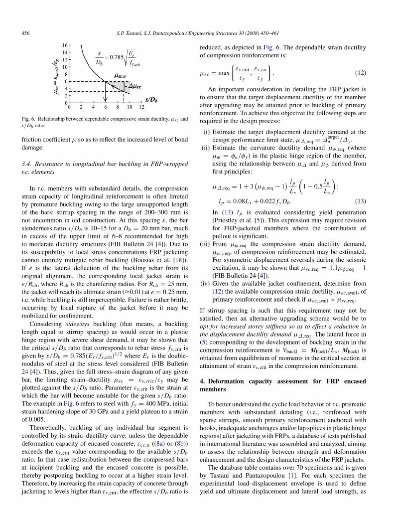
Fig. 7. (a) Comparison between experimental and analytical yield displacementestimates and (b) experimental strength values normalized to the ideal flexuraland anchorage strengths (empty square = control, black square = retrofittedspecimens).
illustrated in Fig. 1: the characteristic points in the envelopecorrespond to 80% of the peak load, Vu . Fig. 7(a) plotsexperimental estimates of yield displacement (defined as perFig. 1) after being normalized by the calculated result from twopopular models, i.e.:
1. The estimated yield displacement using classical mechanics(∆y,mech = φy L2
s /3) and2. the flexural-slip component of the yield-displacement as
proposed by Priestley et al. [5] (∆y,Priestley = φy(Ls +
0.022 fy Db)2/3, MPa, mm), where φy is the yield
curvature. The shear component is neglected in thiscalculation because it is deemed insignificant as comparedwith rotations owing to flexure and reinforcement pullout.
From Fig. 7(a) it is concluded that both analytical estimatesfall well below the experimental value for yield displacementwith the worse estimates resulting from the classical model.Underestimation of yield displacement indicates that the actualslip contribution is larger than calculated.
For all specimens, the ideal flexural strength Viflex wascalculated from first principles considering the materialproperties given by the researchers. The FRP confinementor strain-hardening of the embedded reinforcement were notconsidered, thereby representing the flexural resistance of themember prior to upgrading (the confining action of embeddedstirrups has been accounted for). From evaluation of the testresults it is confirmed that the behavior under cyclic loading isimproved through FRP jacketing to the extent that prematurebrittle failure modes are suppressed (shear, lap splice failure)so that ductility owing to yielding of embedded flexuralsteel may be realized. In most cases, failure was markedby excessive slippage of longitudinal reinforcement from thesupport (Fig. 7(a)). Few cases report crushing of the concretecompression zone accompanied by buckling of longitudinalreinforcement.
Fig. 7(b) plots the observed strength Vu of the upgradedmember normalized by the calculated value of Viflex onthe y-axis, and by the calculated value of Vanch on the x-axis. Vanch was calculated as per Section 3.3 detailed in thepreceding, using the following values for the parameters: f ′
t =
0.5 f′0.5c , kanch
st = 0.33, ζ = 1, µ = 1.4 and ur,o = 0.05 mm.In the case of bars anchored in a footing stub the contribution
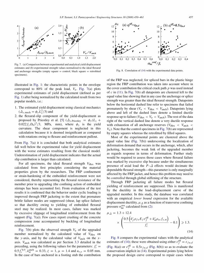
Fig. 8. Correlation of (14) with the experimental data points.
of the FRP was neglected; for spliced bars in the plastic hingeregion the FRP contribution was taken into account where inthe cover contribution the critical crack path p was used insteadof c in (11). In Fig. 7(b) all datapoints are clustered left to theequal value line showing that in any case the anchorage or splicestrength was greater than the ideal flexural strength. Datapointsbelow the horizontal dashed line refer to specimens that failedprematurely by shear (Vu < Viflex < Vanch). Datapoints lyingabove and left of the dashed lines denote a limited ductileresponse up to failure (Viflex < Vu < Vanch). The rest of the dataright of the vertical dashed line denote a very ductile responsewith exhaustion of all anchorage reserves (Viflex < Vanch <
Vu). Note that the control specimens in Fig. 7(b) are representedby empty squares whereas the retrofitted by filled squares.
Most of the experimental points are clustered above theequal value line (Fig. 7(b)) underscoring the localization ofdeformation demand that occurs in the anchorage, which, afterjacketing, becomes the weak link of the upgraded memberas regards response in terms of deformation. Further studywould be required to assess those cases where flexural failurewas marked by excessive slip because under the simultaneouspresence of axial load the P–∆ effects would decimate thedependable flexural strength—this parameter is only marginallyaffected by the FRP jacket, and hence this problem may need tobe controlled through global stiffening of the structure.
Through FRP jacketing all failure modes but flexuralyielding of reinforcement are suppressed. This is manifestedby the ductility in the load–displacement curve of theupgraded member. In this study, the database was correlatedwith an empirical lower bound expression for the availabledisplacement ductility, µ∆ as a function of transverse confiningpressure σ ave
lat calculated from (2):
µ∆ = 1.3 + 12.4
×
0.5(
kcf ρ f v E f ε
efff + kc
stρsv fy,st
)f ′c
− 0.1
> 1.3.
(14)
Fig. 8 compares the experimental values with the analyticalestimates of (14); these were obtained using either εeff
f = ε f u,d
(Fig. 8(a)) or εefff = 0.5ε f u,d (Fig. 8(b)) so as to evaluate the
conservatism implicit in (14). Experimental points lying belowthe proposed design curve correspond to repair cases where
458 S.P. Tastani, S.J. Pantazopoulou / Engineering Structures 30 (2008) 450–461
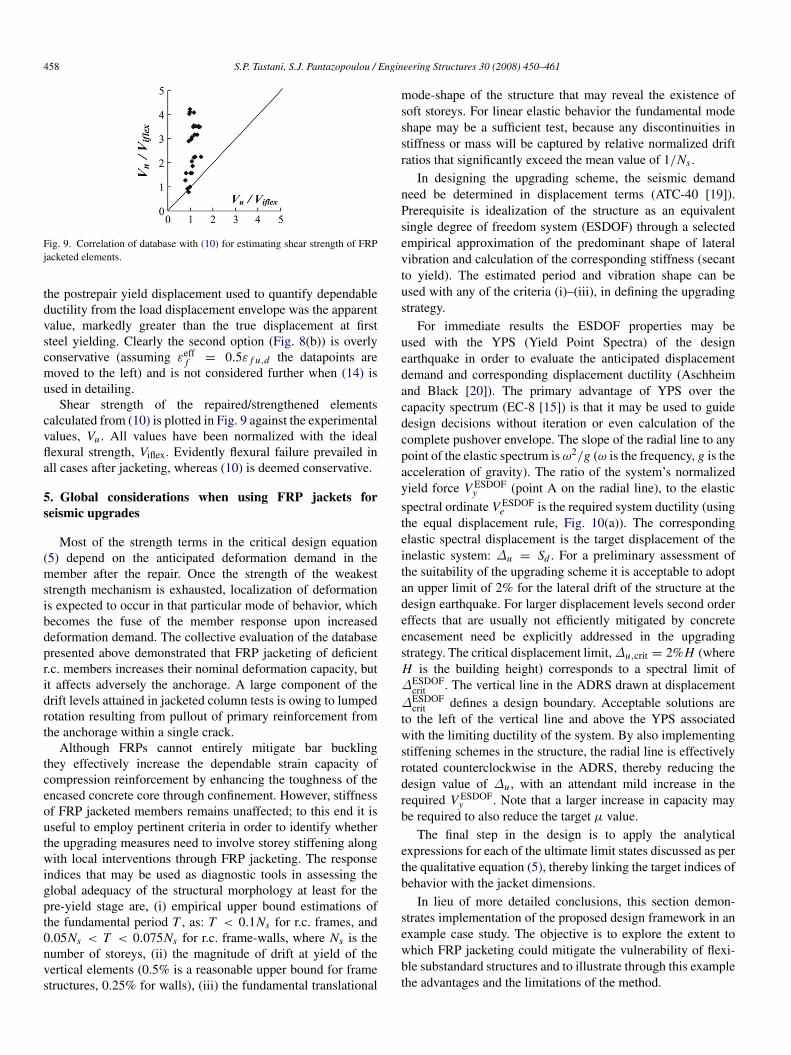
Fig. 9. Correlation of database with (10) for estimating shear strength of FRPjacketed elements.
the postrepair yield displacement used to quantify dependableductility from the load displacement envelope was the apparentvalue, markedly greater than the true displacement at firststeel yielding. Clearly the second option (Fig. 8(b)) is overlyconservative (assuming εeff
f = 0.5ε f u,d the datapoints aremoved to the left) and is not considered further when (14) isused in detailing.
Shear strength of the repaired/strengthened elementscalculated from (10) is plotted in Fig. 9 against the experimentalvalues, Vu . All values have been normalized with the idealflexural strength, Viflex. Evidently flexural failure prevailed inall cases after jacketing, whereas (10) is deemed conservative.
5. Global considerations when using FRP jackets forseismic upgrades
Most of the strength terms in the critical design equation(5) depend on the anticipated deformation demand in themember after the repair. Once the strength of the weakeststrength mechanism is exhausted, localization of deformationis expected to occur in that particular mode of behavior, whichbecomes the fuse of the member response upon increaseddeformation demand. The collective evaluation of the databasepresented above demonstrated that FRP jacketing of deficientr.c. members increases their nominal deformation capacity, butit affects adversely the anchorage. A large component of thedrift levels attained in jacketed column tests is owing to lumpedrotation resulting from pullout of primary reinforcement fromthe anchorage within a single crack.
Although FRPs cannot entirely mitigate bar bucklingthey effectively increase the dependable strain capacity ofcompression reinforcement by enhancing the toughness of theencased concrete core through confinement. However, stiffnessof FRP jacketed members remains unaffected; to this end it isuseful to employ pertinent criteria in order to identify whetherthe upgrading measures need to involve storey stiffening alongwith local interventions through FRP jacketing. The responseindices that may be used as diagnostic tools in assessing theglobal adequacy of the structural morphology at least for thepre-yield stage are, (i) empirical upper bound estimations ofthe fundamental period T , as: T < 0.1Ns for r.c. frames, and0.05Ns < T < 0.075Ns for r.c. frame-walls, where Ns is thenumber of storeys, (ii) the magnitude of drift at yield of thevertical elements (0.5% is a reasonable upper bound for framestructures, 0.25% for walls), (iii) the fundamental translational
mode-shape of the structure that may reveal the existence ofsoft storeys. For linear elastic behavior the fundamental modeshape may be a sufficient test, because any discontinuities instiffness or mass will be captured by relative normalized driftratios that significantly exceed the mean value of 1/Ns .
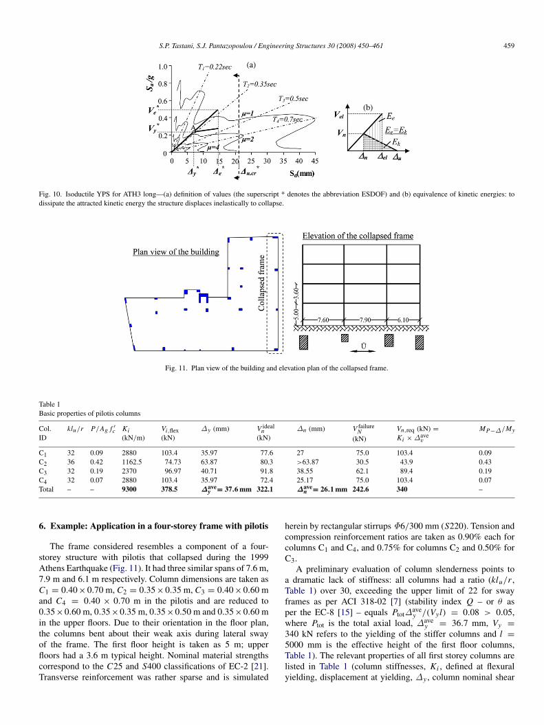
In designing the upgrading scheme, the seismic demandneed be determined in displacement terms (ATC-40 [19]).Prerequisite is idealization of the structure as an equivalentsingle degree of freedom system (ESDOF) through a selectedempirical approximation of the predominant shape of lateralvibration and calculation of the corresponding stiffness (secantto yield). The estimated period and vibration shape can beused with any of the criteria (i)–(iii), in defining the upgradingstrategy.
For immediate results the ESDOF properties may beused with the YPS (Yield Point Spectra) of the designearthquake in order to evaluate the anticipated displacementdemand and corresponding displacement ductility (Aschheimand Black [20]). The primary advantage of YPS over thecapacity spectrum (EC-8 [15]) is that it may be used to guidedesign decisions without iteration or even calculation of thecomplete pushover envelope. The slope of the radial line to anypoint of the elastic spectrum is ω2/g (ω is the frequency, g is theacceleration of gravity). The ratio of the system’s normalizedyield force V ESDOF
y (point A on the radial line), to the elasticspectral ordinate V ESDOF
e is the required system ductility (usingthe equal displacement rule, Fig. 10(a)). The correspondingelastic spectral displacement is the target displacement of theinelastic system: ∆u = Sd . For a preliminary assessment ofthe suitability of the upgrading scheme it is acceptable to adoptan upper limit of 2% for the lateral drift of the structure at thedesign earthquake. For larger displacement levels second ordereffects that are usually not efficiently mitigated by concreteencasement need be explicitly addressed in the upgradingstrategy. The critical displacement limit, ∆u,crit = 2%H (whereH is the building height) corresponds to a spectral limit of∆ESDOF
crit . The vertical line in the ADRS drawn at displacement∆ESDOF
crit defines a design boundary. Acceptable solutions areto the left of the vertical line and above the YPS associatedwith the limiting ductility of the system. By also implementingstiffening schemes in the structure, the radial line is effectivelyrotated counterclockwise in the ADRS, thereby reducing thedesign value of ∆u , with an attendant mild increase in therequired V ESDOF
y . Note that a larger increase in capacity maybe required to also reduce the target µ value.
The final step in the design is to apply the analyticalexpressions for each of the ultimate limit states discussed as perthe qualitative equation (5), thereby linking the target indices ofbehavior with the jacket dimensions.
In lieu of more detailed conclusions, this section demon-strates implementation of the proposed design framework in anexample case study. The objective is to explore the extent towhich FRP jacketing could mitigate the vulnerability of flexi-ble substandard structures and to illustrate through this examplethe advantages and the limitations of the method.
S.P. Tastani, S.J. Pantazopoulou / Engineering Structures 30 (2008) 450–461 459
Fig. 10. Isoductile YPS for ATH3 long—(a) definition of values (the superscript * denotes the abbreviation ESDOF) and (b) equivalence of kinetic energies: todissipate the attracted kinetic energy the structure displaces inelastically to collapse.
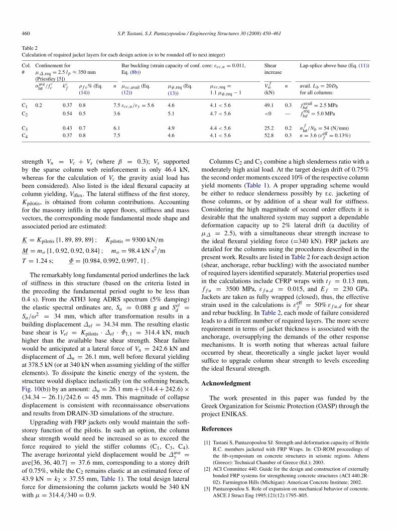
Fig. 11. Plan view of the building and elevation plan of the collapsed frame.
Table 1Basic properties of pilotis columns
Col.ID
klu/r P/Ag f ′c Ki
(kN/m)Vi,flex(kN)
∆y (mm) V idealn
(kN)∆n (mm) V failure
N(kN)
Vn,req (kN) =
Ki × ∆avev
MP−∆/My
C1 32 0.09 2880 103.4 35.97 77.6 27 75.0 103.4 0.09C2 36 0.42 1162.5 74.73 63.87 80.3 >63.87 30.5 43.9 0.43C3 32 0.19 2370 96.97 40.71 91.8 38.55 62.1 89.4 0.19C4 32 0.07 2880 103.4 35.97 72.4 25.17 75.0 103.4 0.07Total – – 9300 378.5 ∆ave
y = 37.6 mm 322.1 ∆aven = 26.1 mm 242.6 340 –
6. Example: Application in a four-storey frame with pilotis
The frame considered resembles a component of a four-storey structure with pilotis that collapsed during the 1999Athens Earthquake (Fig. 11). It had three similar spans of 7.6 m,7.9 m and 6.1 m respectively. Column dimensions are taken asC1 = 0.40×0.70 m, C2 = 0.35×0.35 m, C3 = 0.40×0.60 mand C4 = 0.40 × 0.70 m in the pilotis and are reduced to0.35×0.60 m, 0.35×0.35 m, 0.35×0.50 m and 0.35×0.60 min the upper floors. Due to their orientation in the floor plan,the columns bent about their weak axis during lateral swayof the frame. The first floor height is taken as 5 m; upperfloors had a 3.6 m typical height. Nominal material strengthscorrespond to the C25 and S400 classifications of EC-2 [21].Transverse reinforcement was rather sparse and is simulated
herein by rectangular stirrups Φ6/300 mm (S220). Tension andcompression reinforcement ratios are taken as 0.90% each forcolumns C1 and C4, and 0.75% for columns C2 and 0.50% forC3.
A preliminary evaluation of column slenderness points toa dramatic lack of stiffness: all columns had a ratio (klu/r ,Table 1) over 30, exceeding the upper limit of 22 for swayframes as per ACI 318-02 [7] (stability index Q – or θ asper the EC-8 [15] – equals Ptot∆ave
y /(Vyl) = 0.08 > 0.05,where Ptot is the total axial load, ∆ave
y = 36.7 mm, Vy =
340 kN refers to the yielding of the stiffer columns and l =
5000 mm is the effective height of the first floor columns,Table 1). The relevant properties of all first storey columns arelisted in Table 1 (column stiffnesses, Ki , defined at flexuralyielding, displacement at yielding, ∆y , column nominal shear
460 S.P. Tastani, S.J. Pantazopoulou / Engineering Structures 30 (2008) 450–461
Table 2Calculation of required jacket layers for each design action (n to be rounded off to next integer)
Col.#
Confinement forµ∆,req = 2.5 l p ≈ 350 mm(Priestley [5])
Bar buckling (strain capacity of conf. core: εcc,u = 0.011,Eq. (8b))
Shearincrease
Lap-splice above base (Eq. (11))
σ avelat / f ′
c kcf ρ f v% (Eq.
(14))n µεc,avail (Eq.
(12))µφ,req (Eq.(13))
µεc,req =
1.1 µφ,req − 1V f
w
(kN)n avail. Lb = 20Db
for all columns:
C1 0.2 0.37 0.8 7.5 εcc,u/εy = 5.6 4.6 4.1 < 5.6 49.1 0.3 f availbd = 2.5 MPa
C2 0.54 0.5 3.6 5.1 4.7 < 5.6 <0 — f reqbd = 5.0 MPa
C3 0.43 0.7 6.1 4.9 4.4 < 5.6 25.2 0.2 σf
lat/Nb = 54 (N/mm)
C4 0.37 0.8 7.5 4.6 4.1 < 5.6 52.8 0.3 n = 3.6 (εefff = 0.13%)
strength Vn = Vc + Vs (where β = 0.3); Vs supportedby the sparse column web reinforcement is only 46.4 kN,whereas for the calculation of Vc the gravity axial load hasbeen considered). Also listed is the ideal flexural capacity atcolumn yielding, Viflex. The lateral stiffness of the first storey,Kpilotis, is obtained from column contributions. Accountingfor the masonry infills in the upper floors, stiffness and massvectors, the corresponding mode fundamental mode shape andassociated period are estimated:
K = Kpilotis {1, 89, 89, 89} ; Kpilotis = 9300 kN/m
M = mo {1, 0.92, 0.92, 0.84} ; mo = 98.4 kN s2/m
T = 1.24 s; Φ = {0.984, 0.992, 0.997, 1} .
The remarkably long fundamental period underlines the lackof stiffness in this structure (based on the criteria listed inthe preceding the fundamental period ought to be less than0.4 s). From the ATH3 long ADRS spectrum (5% damping)the elastic spectral ordinates are, Sa = 0.088 g and Sel
d =
Sa/ω2= 34 mm, which after transformation results in a
building displacement ∆el = 34.34 mm. The resulting elasticbase shear is Vel = Kpilotis · ∆el · Φ1,1 = 314.4 kN, muchhigher than the available base shear strength. Shear failurewould be anticipated at a lateral force of Vn = 242.6 kN anddisplacement of ∆n = 26.1 mm, well before flexural yieldingat 378.5 kN (or at 340 kN when assuming yielding of the stifferelements). To dissipate the kinetic energy of the system, thestructure would displace inelastically (on the softening branch,Fig. 10(b)) by an amount: ∆u = 26.1 mm + (314.4 + 242.6) ×
(34.34 − 26.1)/242.6 = 45 mm. This magnitude of collapsedisplacement is consistent with reconnaissance observationsand results from DRAIN-3D simulations of the structure.
Upgrading with FRP jackets only would maintain the soft-storey function of the pilotis. In such an option, the columnshear strength would need be increased so as to exceed theforce required to yield the stiffer columns (C1, C3, C4).The average horizontal yield displacement would be ∆ave
y =
ave{36, 36, 40.7} = 37.6 mm, corresponding to a storey driftof 0.75%, while the C2 remains elastic at an estimated force of43.9 kN = k2 × 37.55 mm, Table 1). The total design lateralforce for dimensioning the column jackets would be 340 kNwith µ = 314.4/340 = 0.9.
Columns C2 and C3 combine a high slenderness ratio with amoderately high axial load. At the target design drift of 0.75%the second order moments exceed 10% of the respective columnyield moments (Table 1). A proper upgrading scheme wouldbe either to reduce slenderness possibly by r.c. jacketing ofthose columns, or by addition of a shear wall for stiffness.Considering the high magnitude of second order effects it isdesirable that the unaltered system may support a dependabledeformation capacity up to 2% lateral drift (a ductility ofµ∆ = 2.5), with a simultaneous shear strength increase tothe ideal flexural yielding force (=340 kN). FRP jackets aredetailed for the columns using the procedures described in thepresent work. Results are listed in Table 2 for each design action(shear, anchorage, rebar buckling) with the associated numberof required layers identified separately. Material properties usedin the calculations include CFRP wraps with t f = 0.13 mm,f f u = 3500 MPa, ε f u,d = 0.015, and E f = 230 GPa.Jackets are taken as fully wrapped (closed), thus, the effectivestrain used in the calculations is εeff
f = 50% ε f u,d for shearand rebar buckling. In Table 2, each mode of failure consideredleads to a different number of required layers. The more severerequirement in terms of jacket thickness is associated with theanchorage, oversupplying the demands of the other responsemechanisms. It is worth noting that whereas actual failureoccurred by shear, theoretically a single jacket layer wouldsuffice to upgrade column shear strength to levels exceedingthe ideal flexural strength.
Acknowledgment
The work presented in this paper was funded by theGreek Organization for Seismic Protection (OASP) through theproject ENIKAS.
References
[1] Tastani S, Pantazopoulou SJ. Strength and deformation capacity of BrittleR.C. members jacketed with FRP Wraps. In: CD-ROM proceedings ofthe fib-symposium on concrete structures in seismic regions. Athens(Greece): Technical Chamber of Greece (Ed.); 2003.
[2] ACI Committee 440. Guide for the design and construction of externallybonded FRP systems for strengthening concrete structures (ACI 440.2R-02). Farmington Hills (Michigan): American Concrete Institute; 2002.
[3] Pantazopoulou S. Role of expansion on mechanical behavior of concrete.ASCE J Struct Eng 1995;121(12):1795–805.

S.P. Tastani, S.J. Pantazopoulou / Engineering Structures 30 (2008) 450–461 461
[4] FIB Bulletin 24. Seismic assessment and retrofit or R.C. buildings. Reportby task group 7.1. Lausanne (Switzerland): International Federation forConcrete; 2003 [Chapter 4].
[5] Priestley M, Seible F, Calvi M. Seismic design and retrofit of bridges.New York: J. Wiley and Sons Inc.; 1996.
[6] FIB Bulletin 14. externally bonded FRP reinforcement for R.C. structures.Report by task group 9.3. Lausanne (Switzerland): InternationalFederation for Concrete; 2001.
[7] ACI Committee 318. Building code requirements for structural concreteand commentary (ACI 318-02). Farmington Hills (Michigan): AmericanConcrete Institute; 2002. 1323 pages.
[8] Brena S, Wood S, Kreger M. Full-scale tests of bridge componentsstrengthened using carbon FRP composites. ACI Struct J 2003;100(6):775–84.
[9] Chaallal O, Shahawy M, Hassan M. Performance of axially loaded shortrectangular columns strengthened with carbon FRP wrapping. ASCE JCompos Constr 2003;7(3):200–8.
[10] Richart F, Brandtzaeg A, Brown R. A study of the failure of concreteunder combined compressive stresses. Engrg. Experiment Station Bull.#185 1928.
[11] Tastani SP, Pantazopoulou SJ, Zdoumba D, Plakantaras V, Akritidis E.Limitations of FRP jacketing in confining old-type reinforced concretemembers in axial compression. ASCE J Compos Constr 2006;10(1):13–25.
[12] Moehle J, Elwood K, Sezen H. Gravity load collapse of building framesduring earthquakes. In: S.M. Uzumeri symposium behavior and design ofconcrete structures for seismic performance. ACI-SP 197; 2002.
[13] EKOS-2000. Greek code for reinforced concrete. Technical Chamber ofGreece; 2000. www.oasp.gr.
[14] NEHRP guidelines for the seismic rehabilitation of buildings. WashingtonDC: Federal Emergency Management Agency; 1997.
[15] Eurocode 8. Design provisions for earthquake resistance of structures(EC-8). Brussels: European committee for standardization; 1998.
[16] Tastani SP, Pantazopoulou SJ. Limit state model for bond of machinedsteel bars: Experimental results. In: CD ROM proceedings 2ndinternational fib congress. 2006.
[17] Lura P, Plizzari G, Riva P. 3D finite-element modelling of splitting crackpropagation. Mag Concrete Res. 2002;54(6):481–93.
[18] Bousias N, Triantafillou T, Fardis M, Spathis L, O’Regan B. Fiber-reinforced polymer retrofitting of rectangular R.C. columns with orwithout corrosion. ACI Struct J 2004;101(4):512–20.
[19] ATC-40. Seismic evaluation and retrofit of concrete buildings. Report no.SSC96-01. California: Applied Technology Council and Seismic SafetyCommission; 1996.
[20] Aschheim M, Black E. Yield point spectra for seismic design andrehabilitation. EERI Earthq Spectra 2000;16(2):317–36.
[21] Eurocode 2. Design of concrete structures (EC-2). Brussels: EuropeanCommittee for Standardization; 2002.