Detailed Specifications for 2 x 200KVA, 415V, 50HZ AC ... · and maintaining an Uninterruptible...
35
Detailed Specifications for 2 x 200KVA, 415V, 50HZ AC three phase 4wire Uninterruptible Power System in parallel configura- tion SCOPE: The scope involves design, supply, installation, testing and commissioning of UPS system along with required battery banks. Pre-dispatch inspection, packing, loading at factory, transportation, unloading at site, storing at site, shifting UPS with battery banks to UPS room where UPS has to be installed, installation including supply of all installation materials including minor civil works, UPS interconnection, initial charging batteries followed by two discharge test, conducting site test including load test, supplying load for the load test, commissioning checks, training the operators at site for a week and handing over the documents as listed in Documentation. A. SUBMITTAL B. Tenderer shall submit the following without which offer will not be considered: 1. Bill of materials clearly indicating the optional items. 2. Product catalogues or equipment brochures. 3. Product guide specifications. 4. System single-line operation diagram. 5. Installation information, including weights and dimensions. 6. Information about terminal locations for power and control connections. 7. Drawings for requested optional accessories. C. The following documents shall be submitted along with Delivery in both hard copy and soft copy: 1. Installation manual, which includes instructions for storage, handling, examination, preparation, installation and start-up of UPS. 2. User manual, which includes operating instructions. 3. As built equipment drawings for the standard solution. 4. Test reports
Transcript of Detailed Specifications for 2 x 200KVA, 415V, 50HZ AC ... · and maintaining an Uninterruptible...

Detailed Specifications for 2 x 200KVA, 415V, 50HZ AC three phase 4wire Uninterruptible Power System in parallel configura-tion
SCOPE:
The scope involves design, supply, installation, testing and commissioning of
UPS system along with required battery banks. Pre-dispatch inspection,
packing, loading at factory, transportation, unloading at site, storing at site,
shifting UPS with battery banks to UPS room where UPS has to be installed,
installation including supply of all installation materials including minor civil
works, UPS interconnection, initial charging batteries followed by two discharge
test, conducting site test including load test, supplying load for the load test,
commissioning checks, training the operators at site for a week and handing
over the documents as listed in Documentation.
A. SUBMITTAL
B. Tenderer shall submit the following without which offer will not be considered: 1. Bill of materials clearly indicating the optional items.
2. Product catalogues or equipment brochures.
3. Product guide specifications.
4. System single-line operation diagram.
5. Installation information, including weights and dimensions.
6. Information about terminal locations for power and control connections.
7. Drawings for requested optional accessories.
C. The following documents shall be submitted along with Delivery in both hard
copy and soft copy:
1. Installation manual, which includes instructions for storage,
handling, examination, preparation, installation and start-up of UPS.
2. User manual, which includes operating instructions.
3. As built equipment drawings for the standard solution.
4. Test reports

5. Warranty card for both UPS and battery
6. Contact details for after sales service and call escalation details
PART 1 - GENERAL
1.1 UPS DEFINITIONS
A. Purpose: The purpose of this specification is to define the design, manufacture
and testing characteristics required in view of supplying, putting into operation
and maintaining an Uninterruptible Power Supply system (referred to as a UPS in
the rest of this document). The UPS system shall be designed to supply depend-
able electric power to:
B. Brief description:
1. The UPS shall be a single UPS, operating in double-conversion mode (also
called on-line mode); it shall be a VFI-type UPS (as per standard IEC 62040-
2), made up of the following components, described in detail in this specifica-
tion:
a. Rectifier
b. Battery charger
c. Inverter
d. Battery
e. Automatic bypass (via a static switch)
f. User and communications interface
g. Battery management system
2. UPS system shall include:
a. Any and all other devices required for safe operation and maintenance, including
circuit breakers, switches, cables, etc.
1.2 WARRANTY
A. The components making up each modular UPS unit (rectifier, charger and invert-
er subassemblies) shall be guaranteed (parts and labour on site) for three years
following the start-up date.
B. The sealed lead-acid battery shall be covered by the same warranty as the UPS.

PART 2 - PRODUCTS
2.1 OPERATING PRINCIPLES
A. The UPS system shall operate in double-conversion mode, described in detail in
this specification.
B. Normal operation (normal AC source available): The rectifier shall supply the
inverter and the charger with DC current. The inverter shall continuously supply
the load with backed up electrical energy and the charger shall float charge the
battery.
C. Operation on battery power (normal AC source not available or outside toler-
ances): Upon failure or excessive deterioration of the normal AC source, the in-
verter shall continue to supply the load from battery power without interruption or
disturbance, within the limits imposed by the battery backup time.
D. Battery recharge (normal AC source restored): When the normal AC source is
restored, the rectifier shall again power the inverter, without interruption or dis-
turbance to the load, while the charger automatically recharges the battery.
E. Transfer to bypass AC source:
1. In case of a major overload or if the UPS shuts down, the static switch shall
instantaneously transfer the load, without a break in the supply of power, to
the bypass AC source if it is available and within tolerances.
2. Transfer of the load back to the UPS output, synchronized with the bypass
AC source, shall be automatic. During transfer, the load shall not suffer an
outage or disturbance in the supply of power.
3. On request, the UPS system may automatically transfer the load with a micro-
interruption (adjustable from 15 to 1000 ms) if a major fault occurs on the
UPS system and if synchronization with the bypass source has not been es-
tablished.
4. In all cases, to ensure load transfer in complete safety, the system shall sim-
ultaneously control all the static switches.
G. UPS maintenance:
1. All power and control electronics of the modular UPS units making up the
UPS system shall be accessible from the front of the UPS.
2. For maintenance purposes, the UPS system shall include an external, me-
chanical, manual bypass system with one-button operation, common to all
modular UPS units.
3. For personnel safety during servicing or testing, this system shall be designed
to isolate the UPS system while continuing to supply power to the load from
the bypass AC source. The UPS shall also include a device making it possi-
ble to isolate the rectifier and the charger of each modular UPS unit from the
normal AC source.
H. Battery maintenance: For safe maintenance on the battery, the system shall in-
clude a circuit breaker to isolate the battery from the rectifier, the charger and the
inverter. When the battery is isolated from the system, the UPS shall continue to
supply the load without interruption or disturbance, except in the event of a nor-
mal AC source outage.
I. Cold Start (normal AC source absent): The battery shall be capable of starting
the UPS if the normal AC source is absent and continue supplying power to the
load within the specified backup time. Cold start on battery power shall be possi-
ble on the condition that the system shall have started at least once on normal
AC power.
2.2 SIZING AND GENERAL CHARACTERISTICS
A. Technology: UPS technology shall be based on IGBT transistors for all the
power converters (rectifier, charger and inverter with variable chopping frequen-
cy).
B. Rating: The UPS shall be sized to continuously supply a load of 200 kVA at a
power factor of 0.9.
C. Battery backup time:
1. The battery backup time in the event of a normal AC source outage shall be
15 minutes, for a load power factor of 0.9.
2. The battery shall be designed for a service life of 10years. It shall be selected
and sized correspondingly, for a load power factor of 0.9.
D. Types of loads accepted:
1. The UPS system shall accept high crest factors without de-rating (kW) to en-
sure correct operation with computer loads and loads where the leading pow-
er factor can reach 0.9.
2. The total harmonic voltage distortion at UPS output (THDU downstream) shall
respect the following limits:
a. THDU downstream ph/ph ≤ 2% for non-linear loads.
E. PFC sinusoidal-current input rectifiers:
1. The UPS shall not draw a level of harmonic currents that could disturb the upstream
AC system, i.e. it shall comply with the stipulations of guide IEC 61000-3-4.
2. The PFC input rectifiers of the modular UPS units, using sinusoidal-current IGBTs,
shall have the following performance levels:
a. Total harmonic current distortion (THDI) upstream of the rectifier not exceeding 5%
b. Input power factor (PF) greater than 0.99 from 50% load upwards.
. F. Outputs without a transformer: To reduce losses, dimensions and weight, the
output of each UPS unit shall be of the transformerless type and the neutral
shall be recreated electronically. G. Efficiency: Overall efficiency (between the rectifier inputs and the UPS output)
shall be greater than or equal to:
1. 94.5% from 50% load to full rated load (In); H. Noise level: The noise level, measured as per standard ISO3746, shall be less
than 75 dBA.
2.3 AC SOURCES
A. Normal AC source (rectifier input): The normal AC source supplying the UPS
shall, under normal operating conditions, have the following characteristics:
1. Rated voltage: 415 V at full rated load Pn.
2. Input voltage range: 250 V (at 30% load) to 470 V.
2. Number of phases: 3, a neutral is not necessary.
3. Frequency: 50Hz ± 10%.
B. Bypass AC source (automatic-bypass input): 1. The characteristics of the bypass AC source supplying the UPS in the event of an
inverter shutdown (maintenance, failure) or an overload (short-circuit, very high in-
rush current) shall be the following:
a. Voltage:415volts, ± 10%
b. Number of phases: 3 ph + N + earth (a non-distributed neutral is possible)
c. Frequency: 50Hz ± 8% (adjustable up to ± 2 Hz)
2. Outside these tolerances, it shall be possible to supply the load, but in downgraded
mode.
2.4 ELECTRICAL CHARACTERISTICS A. Rectifier and charger
1. Supply: The PFC rectifier, drawing sinusoidal current, shall be supplied by
the normal AC source, without a neutral. It shall provide power for the load as
well as charge or float charge the battery. The battery charger shall be sup-
plied by the rectifier to avoid transmitting any AC fluctuations to the battery.
2. Inrush current: A device shall be provided to limit the inrush currents. When
AC power fails and during genset start, the rectifier shall limit the power
drawn by implementing a walk-in for ten seconds.
3. Phase sequence: A device shall check that the phase sequence is correct to
protect the power system from the effects of incorrect connections. The de-
vice shall also check the bypass AC input.
4. Operating mode: The standard charger shall be sufficient to charge the bat-
tery rapidly. For a backup time of 15minutes, battery recharging shall take
less than 6 to 8hours (values after discharge to Pn/2 and recovery of 90% of
total battery charge for a recent battery).
5. Input power factor > 0.99 @ 100% load. 6. Charger regulation and monitoring:
a. The battery recharge system shall include independent regulation and
monitoring devices to ensure conformity with standard NFC 58311.
b. The battery recharge voltage shall be a function of the ambient
temperature in the battery room.
B. Batteries: Each modular UPS unit shall be equipped with its own battery of the:
1. The UPS shall be equipped with a battery of the value regulated sealed tubu-
lar lead-acid type, mounted and wired in a cabinet identical in aspect to that
of the UPS [mounted on shelves] and shall have a service life of 10years.
2. The battery shall be sized to ensure a continuous supply to the inverter for at
least 15minutes, in the event the normal AC source fails, given that the in-
verter is at full rated load, i.e. 200kVA for a power factor PF = 0.9lag.
3. Sizing calculations shall assume an ambient temperature between 0°C and
35°C. battery sizing calculation shall be submitted.
C. Inverter: The inverter shall be sized to supply a rated load of 200kVA at 0.9 PF
and shall satisfy the specifications listed below.
1. Output voltage
a. Rated voltage: 415volts rms, adjustable via the user interface, within
tolerances of +/- 3% in order to take into account voltage drops in the
cables.
b. Number of phases: 3 phases + neutral + earth.
c. Steady-state conditions: Variations in the rated voltage shall be limited
to ± 2% for a balanced load between 0 and 100% of the rated load,
whatever the voltage level on the normal AC source and the DC voltage
level, within the defined limits.
d. Voltage variations for load step changes: Output voltage transients
shall not exceed ± 1% of rated voltage for 0 to 100% or 100 to 0% step
loads. In all cases, the voltage shall return to within steady-state
tolerances in less than 100 milliseconds.
e. Unbalanced conditions: For a load unbalance between phases, the
variation in the output voltage shall be less than 1%.
2. Output frequency a. Rated frequency: - 50Hz.
b. Variations in the free-running frequency: - ± 0.5 Hz,
3. Synchronisation with bypass power
a. When bypass power is within tolerances: To enable transfer to bypass
power, the inverter output voltage shall be synchronised with the bypass
source voltage whenever possible. To that end, during normal operation, a
synchronisation system shall automatically limit the phase deviation
between the voltages to 3 degrees, if the bypass source frequency is
sufficiently stable (within adjustable tolerances of 0.5% to 8% with respect
to the rated frequency).
b. Synchronisation with an external source: It shall be possible to
synchronise with all types of external source.
c. Autonomous operation following loss of synchronisation with by-pass power: When the bypass source frequency deviates beyond these
limits, the inverter shall switch over to free-running mode with internal
synchronisation, regulating its own frequency to within ± 0.02 Hz. When
bypass power returns to within tolerances, the inverter shall automatically
resynchronise.
d. Variation in frequency per unit time: To avoid transmitting to the
inverter any excessive frequency variations on the bypass AC source
when it is within tolerances, inverter frequency variations per unit time
(dF/dt) shall be limited to 1 Hz/s or 2 Hz/s (user defined).
4. Overload and short-circuit capacity: The UPS shall be capable of supply-
ing for at least:
a. 10 minutes a load representing 125% of the rated load
b. 30 second a load representing 150% of the rated load.
c. For the specified power rating of 200kVA, the inverter shall be capable of
current limiting to a peak capacity of 235% for 150 ms to allow highly dis-
turbed transient operating states without transferring the load to the by-
pass.
d. The overload capacity shall be capable of taking into account temperature
conditions for more than ten minutes, by allowing a continuous, 10% over-
load when the temperature is less than or equal to 20°C.
5. Higher power ratings for lower temperatures: It shall be possible to
increase the power rating when the temperature is less than 35°C. The rating
can be raised by +3% for 30°C, +5% for 25°C and +8% for 20°C.
D. Automatic bypass
1. Load transfer to the static bypass: a. The UPS shall be equipped with an automatic bypass comprising a static
switch
b. Instantaneous transfer of the load from the inverter to bypass power and
back shall take place without a break or disturbance in the supply of power
to the load, on the condition that the bypass source voltage and frequency
are within the specified tolerances and that the inverter is synchronised.
c. Transfer shall take place automatically in the event of a major overload or
an internal inverter fault. Manually initiated transfer shall also be possible.
d. If the bypass power is outside the specified tolerances or is not synchro-
nised with the inverter, automatic transfer of the load from the inverter to
bypass power shall take place after a calibrated interruption adjustable
from 15 to 1 000 milliseconds.
2. Static-switch protection: The static switch shall be equipped with an RC fil-
ter for protection against switching over voltages and lightning strikes.
3. Static-switch withstand: For the specified power rating of 200kVA, the stat-
ic switch shall be capable of handling an over current of 18times the rated
current of the UPS to facilitate discrimination within the electrical installation.
E. Discrimination and short-circuit capacity
1. If the bypass power is within the specified tolerances, the static switch shall
make it possible to use the short-circuit power of the bypass source to trip the
downstream protection devices of the inverter.
2. To ensure tripping in a selective manner, the total available power shall be
sufficient to trip protection devices with high ratings (circuit breaker rated In/2
or UR fuses rated In/4, where In is the rated inverter current).
3. If the bypass source is outside the specified tolerances, all the inverters in
operation shall, for the same discrimination requirements, be capable of trip-
ping circuit breakers rated In/2 or UR fuses rated In/4, irrespective of the type
of short-circuit.
F. System earthing (grounding) arrangement (SEA): The UPS shall be compati-
ble with the following system earthing arrangements (SEA):

1. Upstream source SEA: TNS / TNC
2. Downstream installation SEA: TT/ TNS / TNC
3. If the upstream and downstream SEAs are different, galvanic isolation shall
be provided on the normal and bypass lines.
G. Redundancy: The UPS shall be configured with redundant output inverters, each
with semiconductor fusing, and logic controlled contactors to remove a failed
component from the critical bus.
H. Manually-operated bypass Manual bypass and isolating device in the external auxiliary cabinet for total uninter-
ruptible isolation of the UPS shall be provided in order to isolate both the input side and
the output side of the UPS systems for the maintenance without interrupting the supply
to the load.
2.5 MECHANICAL CHARACTERISTICS
A. Mechanical structure: The UPS and batteries shall be installed in cabinet(s) with
an IP 20 / IP 32 degree of protection (standard IEC 60529). Access to the subas-
semblies making up the system shall be exclusively through the front.
B. Cabinet construction The panel thickness of the side and rear covers, as well as the front doors shall be at
least 1.5mm. Suitable stiffeners shall be provided at points subject to high mechanical
loads.
Dimensions: The UPS shall require as little floor space as possible. To gain
space, it shall be possible to install the UPS with the back to the wall or back to
back.
C. Connection:
1. To facilitate connections, all terminal blocks must be easily accessible from
the front when the modular UPS units are installed with the back to the wall.
Entry of upstream and downstream power cables, as well as any auxiliary
cables, shall be possible through the bottom without requiring a false floor.
2. The UPS shall be equipped with an earth-circuit connector, in compliance
with the listed standards. The cables shall comply with the listed standards
and be mounted in compliance with the safety stipulations.

D. Ventilation:
1. System cooling of shall be by forced-air ventilation. To facilitate layout (partic-
ularly when installed back to the wall), air input shall be through the front and
bottom, exit through the top.
2. All power electronics shall be equipped with a redundant ventilation system
including fault detection.
E. Safety:
1. For the safety of maintenance personnel, the cabinet shall be provided with a
manually operated mechanical bypass designed to isolate the rectifier,
charger, inverter and static switch while continuing to supply the load from the
bypass AC source.
2. The UPS shall be equipped with a terminal block for reception of an external
EPO order resulting in opening of the battery circuit breaker and shutdown of
all converters.
2.6 ENVIRONMENT CONDITIONS
A. UPS
1. Operation: The UPS shall be capable of operating under the following envi-
ronmental conditions without loss of performance:
a. Ambient temperature range: 0° C to +35° C.
b. Maximum temperature: 40°C for eight hours
c. Recommended temperature range: +20° C to + 25° C;
d. Maximum relative humidity: 95% at 25° C;
e. Maximum altitude without de-rating: 1000 meters.
2. Storage
a. The UPS shall be designed for storage under the following condi-tions: ambient temperature range: -25° C to +45° C.
2.7 BATTERY MANAGEMENT
A. Batteries are components whose service life is sensitive to operating
conditions, i.e. particular care is required for their management. In addition to
the protective systems, battery management shall be included the systems
listed below.
B. Measurement of actual backup time: The battery function shall be
equipped with the means to know at all times the real backup time available
(AC power available) or remaining (AC power not available), taking into ac-
count the true load on the inverter, the battery temperature and battery age-
ing.
C. Digital battery monitoring
1. The UPS shall be equipped with a system for battery digital management.
2. Based on a number of parameters (percent load, temperature, battery type and
age), the system shall control the battery charge voltage and continuously calculate:
a. The true available backup time
b. The remaining service life.
D. Block by block monitoring
1. To further optimise battery availability and service life, it shall be possible to
equip the UPS to continuously monitor all battery strings and display a block
by block failure prediction.
2. The system shall include the functions listed below.
a. Continuous measurement of the voltage of each block.
b. Continuous measurement of the internal resistance.
c. Identification of faulty blocks (trend curves).
d. Possibility of replacing individual blocks.
e. Remoting of all information via Ethernet, dry contacts or JBus.
2.8 DISPLAY
A. User interface: UPS operation shall be facilitated by a user interface comprising:
1. A graphic display (at least quarter VGA and high resolution are preferable);
2. ON and OFF control buttons (independent of the display);
3. Status indications with mimic panel.
B. Graphic display: The mimic diagram shall enable display of installation
parameters, configuration, operating status and alarms and indication of operator
instructions for switching operations (e.g. bypass). It shall be capable of supervis-
ing a single UPS unit or a parallel system.
1. Display of measurements: It shall be possible to display the following
measurements for any one of the UPS units or for the entire system:
a. Inverter output phase-to-phase voltages
b. Inverter output currents
c. Inverter output frequency
d. Voltage across battery terminals
e. Battery charge or discharge current
f. Rectifier/charger input phase-to-phase voltages
g. Rectifier/charger input currents
h. Crest factor
i. Active and apparent power
j. Power factor of the load
k. Battery temperature
l. Battery percent charge
m. Available backup time
n. The remaining battery service life
5. Display of status conditions and events: It shall be possible to display the
following indications:
a. Load on battery power
b. Load on UPS
c. Load on automatic bypass
d. General alarm
e. Battery fault
f. Remaining battery backup time
g. Low battery warning
h. Bypass AC source outside tolerances
i. Battery temperature
j. Additional information shall be provided in view of accelerating servicing of
the system.
6. Display of operating graphs: It shall be possible to graphically display the
measurements mentioned above on the screen over significant periods.
7. Statistics: Number of overloads, number of transfers to battery power,
cumulative time on battery power, maximum power levels, demand power
levels.
8. Log of time-stamped events: This function shall store in memory and make
available, for automatic or manually initiated recall, time-stamped logs of all
important status changes, faults and malfunctions, complete with an analysis
and display of troubleshooting procedures. It shall be possible to time stamp
and store at least 2 500 events.
C. Controls: The UPS shall comprise the following controls:
1. Two ON and OFF buttons: Located on the front panel of the UPS, they shall
control UPS-unit ON/OFF status. It shall be possible to turn OFF the UPS ex-
ternally via an isolated dry contact.
2. EPO terminal block: The UPS shall be equipped with an emergency power
off (EPO) terminal block for complete system shutdown following reception of
an external control signal. The EPO command shall result in:
a. Shutdown of UPS units;
b. Opening of the static switches on the bypass line and of the battery circuit
breaker;
c. Opening of an isolated dry contact on the programmable card.
3. Alarm reset button: This button shall turn off audio alarms (buzzer). If a new
alarm is detected after clearing the first, the buzzer sounds again.
D. Status indications with mimic panel: Indication of status conditions shall be
distinct of the graphic display.
1. Three LEDs on the control panel on each modular UPS unit indicate the fol-
lowing status conditions:
a. Load protected;
b. Minor fault;
c. Major fault.
2. The mimic panel shall represent the modular UPS and indicate the status of
the load supply using five two-colour (red and green) LEDs:
a. Load supplied (LED at UPS output on mimic panel),
b. Inverter on (inverter LED on mimic panel),
c. Operation on battery power (LED between battery and inverter on mimic
panel),
d. Bypass activated (bypass LED on mimic panel),
e. PFC rectifier on (rectifier LED on mimic panel).
3. A buzzer shall warn the user of faults, malfunctions or operation on battery
power.
2.9 COMMUNICATION
A. Standard communication: It shall be possible to remote the following controls,
indications and measurements. To that end, the UPS shall have as standard
equipment:
1. A programmable card with four inputs and six outputs.
B. Communications options: The UPS shall be designed to enable the extension
of communications, without system shutdown, to the following types of cards:
1. Multi-standard communications card with two outputs:
a. An RS485 serial-link implementing the ModBus protocol for connection to
a building management system (BMS)
b. Ethernet 10/100 Mbps using one of the protocols below:
2. XML-Web for direct UPS connection to an intranet network, without
connection to a server, capable of supplying information via a standard web
browser SNMP for connection to a computer-network management system
a. Multi-standard communications card with three outputs:
1) The two outputs listed above
2) Plus a modem output for communication with a tele-maintenance
system.
b. Shutdown and administration software shall be available in addition to the
communication cards.
PART 3 – EXECUTION 3.1 PROTECTION
A. UPS: The UPS shall include protection against AC-source over voltages (as per
standard IEC 60146), excessive external or internal temperature rise and vibra-
tions and impacts during transport.
B. Rectifier and charger: 1. The rectifier shall automatically shutdown if the temperature exceeds the
specified limits.
2. The charger shall automatically shut down if the DC voltage reaches the
maximum value specified by the battery manufacturer or if the temperature
exceeds the specified limits.
C. Inverter: Inverters shall self-protect against overloads and short-circuits, irre-
spective of the operating mode (AC power or battery power).
C. Batteries: Battery specification is given in the end of this specification
1. Protection against deep discharge: The UPS shall comprise a device de-
signed to protect the battery against deep discharges, taking into account the
characteristics of the discharge cycles, with isolation of the batteries by a cir-
cuit breaker.
2. Independent regulation and monitoring system: a. A regulation system shall regulate the battery voltage and the charge cur-
rent.
b. A second system, independent of the regulation, shall monitor the battery
voltage and the charge current. Consequently, if the regulation system
fails, the monitoring system steps into shut down the charger and avoid
overcharging.
3. Regulation of the battery voltage depending on the ambient tempera-ture: a. A temperature sensor adapts the charge voltage of each charger to the
ambient temperature.
b. This regulation system takes into account the chemical reaction and pro-
longs the battery service life.
c. The permissible temperature range is set in the personalisation parame-
ters.
d. An alarm shall be issued for temperatures outside the permissible range.
4. Self-test: a. The battery shall be equipped with a self-test that can be run:
1) On request via a manual control
2) automatically according to user-set time intervals.
b. The self-test shall enable updating of battery parameters and detection of
all abnormal conditions in view of preventive maintenance.
3.2 MAINTAINABILITY
A manual bypass shall be available to completely isolate the UPS for mainte-
nance purposes.
A. Local and remote diagnostics and monitoring - E. Services: The UPS shall
be equipped with a self-test system to check operation of the system as a whole
each time it is started. To that end, the supply control/monitoring electronics shall
offer:
1. Auto-compensation of component drift;
2. Acquisition of information vital for computer-aided diagnostics or monitoring
(local or remote);
3. Overall readiness for remote supervision services provided by the manufac-
turer.
3.3 STANDARD AND TESTS
A. Standards
1. All equipment shall be designed and built in accordance with accepted engineering
practice and applicable international standards, in particular the standards listed be-
low.
a. IEC 60140-4: UPS - Performance.
b. IEC 62040-1 and EN 62040-1: UPS - Safety.
c. IEC 62040-2 and EN 62040-2: UPS - Electromagnetic compatibility (EMC), level B.
d. IEC 62040-3 and EN 62040-3: UPS - Performance.
e. IEC 60950 / EN 60950: Safety of IT equipment, including electrical business equip-
ment.
f. IEC 61000-2-2: EMC, levels of compatibility..
g. IEC 61000-3-4: Limits for harmonic current emissions (equipment input current > 16
A/ph).
h. IEC 61000-4: EMC – Immunity tests.
j. IEC 439: Low-voltage switchgear and control gear assemblies.
k. IEC 60529: Degrees of protection provided by enclosures (IP Code).
l. ISO 3746: Sound power levels.
m. CE marking.
2. The equipment shall comply with eco-design and eco-manufacturing criteria
in view of sustainable development and to that end, the manufacturer shall
be able to demonstrate:
a. R&D and production on an ISO 14001 certified site
b. Manufacture with over 90% recyclable materials
c. Capacity to recover products at the end of their service life and provide
proof of destruction by a certified organisation
d. The environmental profile of the product, which shall be supplied with the
sales offer.
B. Certification of conformity: The manufacturer shall provide, on request, a
complete qualification file demonstrating compliance with the above standards.
The indicated levels of performance shall be confirmed by certification from inde-
pendent laboratories (e.g. TÜV or Veritas).
Tests
At manufacturer’s place: The following test shall be carried out in the presence of
department’s engineer before dispatch.
§ Battery simulation test.
§ Static voltage and frequency stability under varying loads and operat-
ing states as per specification
§ Output distortion factor at rated load
§ Short-circuit performance
§ Mains perturbation
§ Efficiency data
If UPS is imported, test report shall be supplied at the time of delivery.
3.4 QUALITY SYSTEM AND TEST PROCEDURES A. Test procedures: 1. The manufacturer shall provide proof of a quality-assurance system. In particular,
the main manufacturing steps must be subject to suitable tests such as:

a. Inspection of incoming components, tests on discrete subassemblies
b. Complete functional checks on termination of manufacture.
2. The equipment shall be subject to burn-in under load conditions prior to shipping.
3. Final checks and adjustments shall be recorded in a report drafted by the quality-
inspection department of the supplier.
4. Certification of the industrial facilities in compliance with ISO 9001 or 9002 shall be
required.
B. Quality system: The UPS must be designed using an ISO 9001 quality system
and a dependability study to ensure maximum reliability.
Transportation Transportation, delivery of the UPS system to the construction site or dispatch ad-
dress and unloading from the heavy goods vehicle including mobile crane / fork lift as
required shall be in the scope of the vendor. Hence it is requested the vendor to famil-
iarise them self in advance of the on-site conditions and the facilities for on-site deliv-
ery.
Commissioning Commissioning checks/ tests of the UPS system shall be done as listed below
§ Inspection of incoming and outgoing cables § Functional test § Input voltage failure § Restoration of the input voltage § Fault simulation The tests shall be carried out in the presence of the department engineers and recorded
in a report. Test is to be carried out during normal working hours, from Mondays to
Fridays from 8:30 a.m. to 4:30 p.m.
3.5 SERVICES
A. Maintenance: The supplier shall propose contracts covering four levels of
maintenance.
1. Level one: simple checks and settings, procedures accessible without any
dismounting and involving no risk.
2. Level two: preventive maintenance, checks not inhibiting continuous opera-
tion of the system and preparing operators for Manufacturer services.

3. Level three: trouble-shooting. Repairs by standard exchange of subassem-
blies and functional power and control components. Preventive-maintenance
operations, both systematic and when indicated by qualified diagnosis.
4. Level four: major preventive and corrective maintenance operations or tech-
nical upgrades during start-up, operation or renovation of the UPS installation
and recycling of equipment or components representing a risk. These opera-
tions require the use of devices and means that have been calibrated by cer-
tified organisations.
B. Technical competency:
1. Customer operators: the supplier shall offer a level 2 training program.
2. Service personnel: the supplier shall ensure that service personnel are
qualified for level 4.
C. Functional components - organisation of supplier’s services:
1. Sufficient geographical proximity of the supplier or an authorised agent shall
ensure reasonable access times to the customer site in view of reducing the
mean time to repair (MTTR). The supplier shall be in a position to offer a con-
tract limiting the response time to four hours.
2. The supplier's logistics system and the availability 24 hours a day of original
replacement parts shall similarly contribute to reducing to the greatest extent
possible the mean time to repair (MTTR).
D. System start-up: The system and equipment shall be started up on site by the
supplier or its authorised agent. The procedure shall include checks on the char-
acteristics of the upstream and downstream protection devices and on the UPS
installation parameters.
E. Replacement parts: The suppler shall undertake to provide certified original re-
placement parts for at least ten years following the date of delivery.
3.6 INSTALLATION SERVICES A. Required services include:
1. Supply of the UPS and any necessary parts or elements.
2. UPS transportation and delivery to the site.
3. UPS handling and installation on the site.

4. Connections between the battery and the UPS.
5. Connection of the normal AC source to the rectifier/charger.
6. Connection of the bypass AC source to the input transformer or bypass input.
7. Connection of the load circuits to the UPS output.
OTHER REQUIREMENT: 1. If air conditioning is required for battery and UPS, recommended AC system
shall be furnished.
2. Validity of the offer shall be 120 days from the date of opening of technical bid.
3. Place of Installation shall be at Bylalu village, IDSN campus (Chandrayaan
campus) Bangalore.
4. The offer shall be exclusive of all taxes, duties, octroi, etc and shall be clearly
indicated.
5. Payment: 67.5% against delivery, 12.5% against installation, 10% against test-
ing and commissioning of complete UPS system and 10% against handing over of
system with document and training
6. Warranty: The fully assembled UPS system with battery banks shall be war-
ranted for a period of 36months from the date of commissioning.
7. Security deposit: 10% on the contract value shall be submitted immediately on
completion of work which will be refunded after successful completion of warranty
period. Bank guarantee may be submitted in lieu of security deposit.
8. EMD: EMD for the value of Rs 1,00,000.00 in the form of bank guarantee or DD
shall be submitted with the offer without which offer will not be considered. EMD
paid will be returned after completion of work and the receipt of security deposit
from the successful tenderer. EMD will be returned to all unsuccessful tenderer
immediately upon finalizing order.
SPECIFICATION FOR VALVE REGULATED (SEALED) LEAD ACID STATION-ARY BATTERY FOR UPS BACK UP Definitions: Valve regulated Lead Acid (VRLA) Battery: A lead acid battery with an immobi-
lized electrolyte that is sealed in terms of electrolyte maintenance. The battery
contains a pressure relief valve that releases internal pressure to the atmosphere
when the cell pressure exceeds a manufacturer’s prescribed level. The immobiliz-

ing electrolyte medium accommodates an oxygen recombination cycle thus mini-
mizing gassing and water consumption.
1. This specification requires reference to the following standards:
IEEE 1189: Guide for selection of valve regulated lead acid batteries for stationary
applications
IEEE 1187: Recommended practice for installation design and installation for se-
lection of valve regulated lead acid batteries for stationary applications
IEEE 1188: Recommended practice for maintenance, testing and replacement of
valve regulated lead acid batteries for stationary applications
Design shall be in accordance with IEC 60896-21/22
.
1.1. Service life of the battery shall be not less than 10years.
2. Constructions: VRLA battery shall be absorbed glass mat construction or gel type.
2.1: Inter-cell connections: The inter-cell connections shall be sufficiently robust
to withstand a 1minute short circuit condition without damage to either the connec-
tion or the container and the cover assembly.
2.2: Valve: The valve shall operate at the specified pressure and tolerance limits.
The valve shall not allow ingress of air into the unit. All the cells shall be subjected
to pressure test up to 10 psi. The vent plug used shall be explosion resistant and
self-re-sealing and pressure regulating type. Vent plug shall be such that it cannot
be opened without proper tool.
2.3: Nuts and Bolts: Nuts and bolts for connecting the cells shall be made of cop-
per, brass or stainless steel and effectively lead coated to prevent corrosion. Stain-
less steel bolts/nuts can be used without lead coating. Stainless steel used shall
be of special grade which is resistant to sulfuric acid.
3. Performance: 3.1: Rated capacity: Batteries shall be rated in watts per block at constant power
discharge at 25ºC for 15minutes discharge rate to 1.67V per cell. Batteries shall be
rated in ampere hour at constant current discharge at 25ºC for 10 hour (C10) dis-
charge rate to 1.67V per cell. Ampere hour efficiency shall be better than 90% and
Watt hour efficiency batter than 80%.
3.2: Storage life: The block shall have discharge of not more than 5% per month
at 25ºC and shall be capable of being restored to full rated capacity after 6months
storage at 25ºC utilizing the battery manufacturers recommended freshening
charge practice.
3.3: Ripple current tolerance: The battery shall be able to withstand upto 5 am-
pere per 100 ampere-hour rated capacity at the 20hour rate without significant
heating less than 1ºC or degradation in the expected life.
3.4: Thermal runaway Resistance: The battery shall be capable of withstanding
the following conditions without entering thermal runaway.
2.4volts per cell charging voltage at 40ºC – indefinite
2.45volts per cell charging voltage at 40ºC – 168hours
2.5volts per cell charging voltage at 40ºC – 72hours
3.5: Quality assurance: The batteries shall be manufactured as per ISO
9001:2000 quality assurance procedure laid down so as to meet the requirement
of the specification. The Routine tests shall form a part of the QA procedure and
records maintained. Amongst other requirements of the specification, validation
and system monitoring of QA procedure shall form a part of type approval. The
necessary Plant & machinery and Test instruments shall be available with the
manufacturer to ensure compliance to the approved QAP.
4: Acceptance test: The acceptance tests shall be performed at the manufactur-
er’s premises before dispatch in the presence of department engineer if batteries
manufactured in India or the acceptance test shall be conducted at site if batteries
are imported.
The following shall constitute the acceptance tests
a) Test for capacity
b) Test for voltages during discharge.
5: Packing: Vendors/tenderers shall be responsible for safe transportation of cells/
battery, which should be packed and delivered in good condition to the respective
site as indicated in the tender. If there is any damage, vendors/tenderers shall re-
place the damaged cell/ battery free of cost.
6: Manual of instructions: Two copies of instruction manual of initial treatment
and routine maintenance during service shall be supplied by the manufacturer
along with every set of battery.
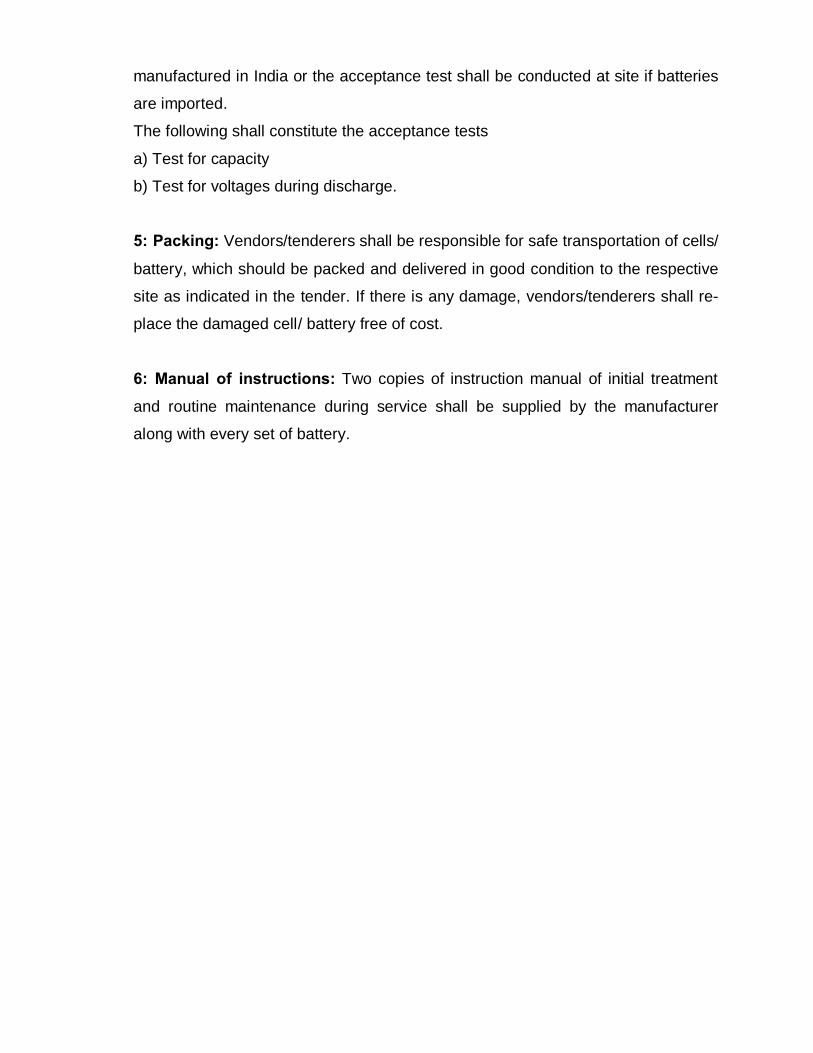
Information as per format given below is to be furnished by the tenderer in techno-commercial bid failing which offer will not be considered
UPS SYSTEM – 2 x 200 KVA
Sl. No.
Indent specification Tenderer’s specification Remarks
1. UPS RATING KVA 200 KW 180 at 0.9 log
2. Qty : 1set consist of UPS unit 2nos and battery bank 2nos
3. Make
4. Series
5. Model
6. Output Power factor at full rated load :0.9lag
7 Output wave form : sine wave 8. Overload capacity:
150% for 60 sec
9. Overload capacity: 125% for 10min
10. Output voltage distortion factor < 1% with linear, <2% with non-linear load
11. Maximum crest factor 3
12. Maximum input current at rated load & power factor
13. Maximum input current with bat-tery charging(line current)
14. Maximum input current without battery charging (line current)
15. Battery charging current max .
16. Rectifier / Charger Technology IGBT
17. Type of Rectifier/ Charger IGBT
18. Battery Management system It shall compliance to the de-tailed specification
UPS SYSTEM – 2 x 200 KVA
Sl. No.
Indent specification Tenderer’s specification Remarks
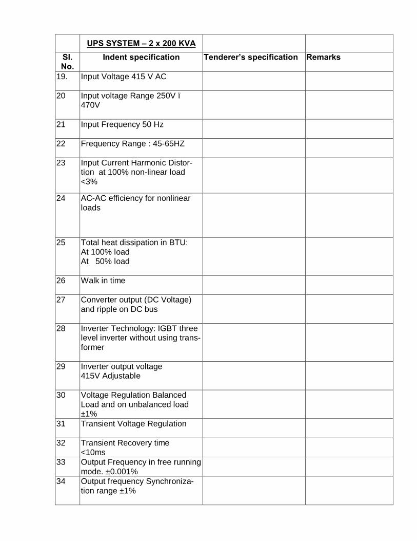
19. Input Voltage 415 V AC
20 Input voltage Range 250V – 470V
21 Input Frequency 50 Hz
22 Frequency Range : 45-65HZ
23 Input Current Harmonic Distor-tion at 100% non-linear load <3%
24 AC-AC efficiency for nonlinear loads
25 Total heat dissipation in BTU: At 100% load At 50% load
26 Walk in time
27 Converter output (DC Voltage) and ripple on DC bus
28 Inverter Technology: IGBT three level inverter without using trans-former
29 Inverter output voltage 415V Adjustable
30 Voltage Regulation Balanced Load and on unbalanced load ±1%
31 Transient Voltage Regulation
32 Transient Recovery time <10ms
33 Output Frequency in free running mode. ±0.001%
34 Output frequency Synchroniza-tion range ±1%

UPS SYSTEM – 2 x 200 KVA
Sl. No.
Indent specification Tenderer’s specification Remarks
35 Power loss at 100% load
36 Wave form
37 Total Harmonic Distortion at out-put <1% with liner load and <2% with non- liner load
38 Crest Factor
39 Phase Voltage displacement <1%
40 Short circuit performance when invertor on battery mode and mains failure 300% for 10ms
41 Max. non-liner load 100% 42 Bypass Static Switch
43 Rated voltage 415V
44 Voltage tolerance ±10%
45 Rated frequency 50Hz
46 Frequency tolerance ± 10%
47 Overload capacity 150% 10min
48 Change over time From inverter to bypass From bypass to inverter in synchronization mode and non-synchronization mode: 0 ms
49 Cooling method adopted / type of cooling
50 Environnemental protection 51 Audible Noise in dbA at 1 Mtr.
52 Degree of Ingress protection
53 Batteries:

UPS SYSTEM – 2 x 200 KVA
Sl. No.
Indent specification Tenderer’s specification Remarks
Type: 12V VRLA maintenance free
54 No. of Battery Panels per UPS
55 Whether inter-cell / Row / Tier connection included in the Bat-tery offered.
56 Battery backup time 15 min 54 Battery bank voltage 55 No. of Battery per bank as de-
signed
56 Battery capacity in AH for 10 hour discharge rate
57 Battery make
58 Model 59 Efficiency AC/AC (overall)
a) At full load b) At 75% load c) At 50% load d) At 25% load
60 Reliability
61 MTBF 62 MTTR 63 Details of External Maintenance
bypass switch offered
64 Details of Remote monitoring of-fered
65 Whether Power paralleling kit is included for parallel redundant system
66 Battery monitoring system with temperature sensor is included
67 List of test offered at factory and at site is furnished

SCHDULE OF MATERIALS WITH APPROXIMATE QUANTITES
Sl.no Description Quantity Unit Unit price
Rs. P Amount Rs. P
1 Supply of 200KVA UPS consist of 2 UPS units working in redundant / power paralleling
1 set
2 Supply of ---- AH, 12V each set of 2 battery banks, each battery bank consist of ------ nos mono-block battery/ cells and 2nos battery breaker provided externally
1 set
3 Supply of paralleling kit 1 each 4 Supply of remote display panel for
each UPS 2 each
5 Supply of maintenance bypass switch with enclosure
1 each
6 Supply of communication cable for remote display panel from UPS in-cluding laying through metal con-duit and end connections
1500 RM
7 Supply of Nyvin cables size-0 for input cable from UPS input panel to UPS; from UPS to UPS output and UPS to Battery bank through battery breaker including laying through PVC flexible conduit and end connections with C8 rated copper lugs.
1200 RM
8 Custom duty/ Excise duty as appli-cable @---- %. Note: Custom duty exemption certificate/ Excise duty exemption certificate will be is-sued.
9 Sales tax @ --- % 10 Packing, forwarding, transport and
delivery charge including insur-ance
11 Installation, testing and commis-sioning of UPS
1 set
12 Installation, testing and commis-sioning of Battery banks
1 set
13 Service tax @ ----% 14 Total Note: 1) RM indicated in the unit column means running meter.

2) Cables shall be supplied based on the site assessment and payment will be made for actual usage of cables. Hence quantity indicated for cable supply is in-dicative and site variable quantity.

--51.
Item Name of IINo.
Finolex, Rallison, L &'[ ,
1 PVC wires Anchor, RR Kabel, Rei.IAVOCAS, Darshan PiliEON ( INDO KOPP), ,;~
Flush type switches and Cona, Anchor, Leader,2
5A/15A sockets M.K., Toyama, Legran:Western, LK, Finoswit~~Anchor (Roma), Lisha,
Modular (plate type) switches Toyama, Vega, LitaskL3 GELCO, ASS,North-Wand 5A/15A sockets
Kolors, Finoswitch(Fin<EON ( INDO KOPP), Ij
Sockets, Plugs (with Poly Sest & Crompton, Cye!
4 carbonate, FRP or metal clad (MOS), Crompton Gre:North-West, Clipsal (S<body)Hensel.Anchor, MK. Gelco, Cn
5 Electronic Fan Regulators Electric, Oecon, Rider,ASS, North-West, Fin(~Philips, GE lighting, WI
6 a. Light fittings Greaves, Thorn lightin;Havell's, Jaquar, Osra
~6b. Lamps Same makes under iter-
7 Lighting Management System Lutron, Schneider, Phi i-
8 Light fittings: Out doorSame makes under iterapplications only
-9 Energy efficient fittings with In addition to makes un
T5 Lamps also.-10 Emergency light fittings Philips / SPL / IMCO.
11 Electronic time switch L & T, Siemens, Duke, I
Legrand (MOS).-
12 Ceiling fans & Pedestal/wall GEC, Usha, Khaitan, CImounted fans Orient, Rallis, Havells ,
13 Exhaust fans GEC, Khaitan, Sajaj,Pe,Crompton Greaves, Us
14 Air circulators GEC, EPC, Bajaj, Khai':Almonard.
15 Flame proof light fittings Baliga, FLEXPRO, STJFCG-Flame Proof Cont
Flame proof switchgear and Saliga, FCG-Flame Pro16
accessories Ltd., Felxpro, SterlingFlame pack.
17 Geysers Racold, Bajaj, Johnson,Voltas, USHA, CromptcLegrand (MOS), Havell~
Miniature circuit breakers Siemens, Indo Kopp sa18 (MCSs) Oatar, HPL, Standard,
~Hager,AREVA T&O, AlC&S.
nd / make
Iysocables, Q Flex,Jandha cable,StandardLAPP kabel,ster, V-Guard.isha, Record, Vega,MOS), Sonata,Finolex).K, Legrand (MOS), LK,::hneider, Crabtree,:, Clipsal (Schneider),K), L&T, Standard,er.BCH-Electric, Legrands, Havells, ASS,
lIeider), Standard,
pton Greaves,:grand (MOS), Litaski,~itch(Finolex).
: 0, Crompton
E:AJAJ, Surya Roshini,
-{la.-;, Honeywell.-E;, K- Lite, Ligman.
-! - item 6, AS IAN E+
-
-rlics, SCH-Electric,
-r lpton Greaves,!iaj.
r EPC,
:. Crompton Greaves,
-L, Crompton GreavesI 3ears, Sajaj.
(;ontrol Gears Pvt.I tchgears, STAHL,
-E,nus, Remson,AO Smith.
\/ersatrip, GE,lille, Indo-Asian, S&S,
Elcon, Schneider,, North-West, L& T,
-
.' 0'
LIST OF APPROVED MAKES WITH EFFECT FI::OM 14-10-2013
c'...>
,\
,i!S,
10
L.I (
~{M
::H".,...)
LE;,V:>/
1.
r1
'I
:Ie
I)
:!c
113haan
, '-I")
vIt,
iHJI3
-_51._ -- -
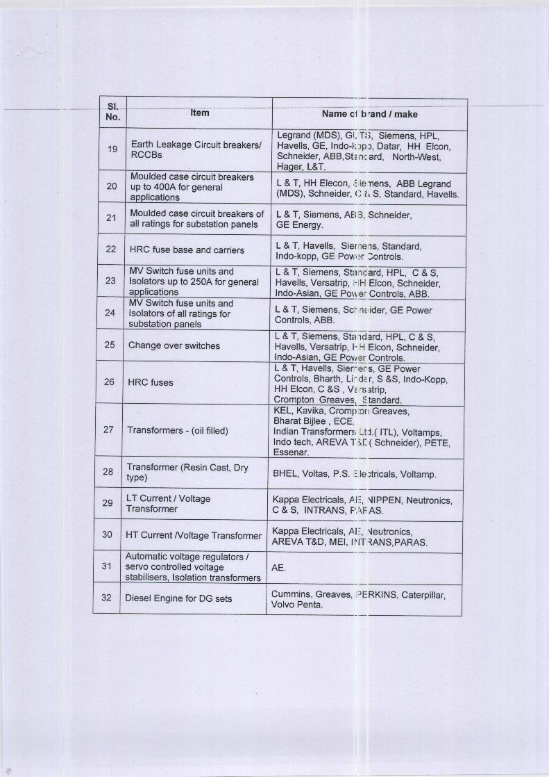
No. Item --Name c1
Legrand (MDS), GI.
19Earth Leakage Circuit breakers/ Havells, GE, Indo-I:RCCSs Schneider, ASS,St,
Hager, L&T.-Moulded case circuit breakers
L & T, HH Elecon,:20 up to 400A for generalapplications (MDS), Schneider, (
-
21 Moulded case circuit breakers of L & T, Siemens, AEIall ratings for substation panels GE Energy.
-22 HRC fuse base and carriers L & T, Havells, Sier
Indo-kopp, GE Pow,
MV Switch fuse units and L & T, Siemens, Sta23 Isolators up to 250A for general Havells, Versatrip, 1-
applications Indo-Asian, GE PO\~MV Switch fuse units and
L & T, Siemens, Scr24 Isolators of all ratings forsubstation panels Controls, ASS.
L & T, Siemens, Stet25 Change over switches Havells, Versatrip, l-
Indo-Asian, GE Po~~L & T, Havells, Sier-
26 HRC fuses Controls, Sharth, Li-HH Elcon, C &S , V,Crompton Greaves!KEL, Kavika, CrompSharat Sijlee , ECE
27 Transformers - (oil filled) Indian TransformeniIndo tech, AREVA TEssenar.
28 Transformer (Resin Cast, DrySHEL, Voltas, P.S.type)
29 LT Current / Voltage Kappa Electricals, PTransformer C & S, INTRANS, F'
30 HT Current Noltage Transformer Kappa Electricals, AAREVA T&D, MEI, II
Automatic voltage regulators /31 servo controlled voltage AE.
stabilisers, Isolation transformers
32 Diesel Engine for DG sets Cummins, Greaves,Volvo Penta.
rand I make
>, Siemens, HPL,J, Datar, HH Elcon,ard, North-West,
Tlens, ASS Legrand, S, Standard, Havells.
Schneider,
ns, Standard,:;ontrols.
-ard, HPL, C & S,Elcon, Schneider,
-Controls, ASS.
E,ider, GE Power
13rd, HPL, C & S,Elcon, Schneider,
. Controls.
. s, GE Power: r, S &S, Indo-Kopp,; 3trip,: tandard.rl Greaves,
t t( ITL), Voltamps,: ( Schneider), PETE,
-
! ;tricals, Voltamp.
-'JIPPEN, Neutronics,
I; AS.-'Jeutronics,.~ANS,PARAS.
-
-ERKI NS, Caterpillar,
-
".'
-- b
T:
iE!:: I
nd11-1
n
'1(
H
:0
::IE
I::,
.\

No..
Item.___ _______Name-of-
33.Alternators for DG sets Stamford- AVK, CrorY,
a. Leroy Somer.
33.HT Alternators for DG sets Same makes as itemb.
Armoured HT power cable Hindustan Vidyut Pro,34 (both PVC and XLPE) Universal, Finolex, C<
Polycab, KEllndustriEHindustan Vidyut Pro,
35 Armoured LT power cable INCAS, Polycab, Uni\(both PVC and XLPE) Torrent, Nicco, Havell
Rallison, TERA, Unic,Armoured and Unarmoured Hindustan Vidyut Proc
36 control cable INCAS, Polycab, Uni\(both PVC and XLPE) and Torrent, Nicco, Havellspecial purpose cables advance cable.
Unistar, Mehar, Asian37 LT Capacitors Greaves, Khatau Junl
EPCOS, ASS.
38 Automatic Power factor Seluke, Power MonitcCorrection Relay T&D.
39 LT Air circuit breaker L & T, Siemens, GE,'Schneider (Merlin-Gel
40 Overload relays with built-in L & T, Siemens, GE FSingle phase preventors Schneider.
Siemens, Andrew YUlE
41 11 kV Vacuum circuit breakers Salmer Lawrie, Alind,Crompton Greaves, A
Analog instruments: Nippen, MECO, AE, H42 Ammeter, Voltmeter,Frequency meter, PF meter L &T, Rishab, Riken.
Digital type instruments: Clectro systems, AE, I43 Ammeter, Voltmeter, Digital, CG Schlumbel
Frequency meter, PF meter Prok dv's..
44 Load Manager Meters AE, Conzerv, L&T.
45 Static Power meter and logger Conzerv, CG Schlumt
46 Single and three phase Energy Remco (SHEL), Havelmeters Jyothi, ECE, UE, Capi
47 Air break power/ Control L & T, Siemens, GE, EContactors Greaves, ASS, Telem
md./-make
n Greaves,
I above and TDPS.
ts Ltd (HVPL), INCAS,~PG,Torrent, Nicco,
3loster, Havell's.ts Ltd, (HVPL), Gloster,ai, Finolex, CCI, RPG,KEI Industries,
ts Ltd (HVPL),Gloster,ai, Finolex, CCI, RPG,,app Kabel,Rallison,
)rague, CromptonSiemens, L & T,
:onzerv, L & T, AREVA
:hi, ASS, C & S,
er controls, ASS,
lEI, Jyothi,EVA T&D( Schneider),Easun Reyrolle, L&T.
~lIs,Neutronics,
T, Conzerv, GE" MECO, Rishab,
:er.
Siemens, MET, Alind,L & T, Conzerv.
I-Electric, Cromptonanic, C & S.
"
--
ptc
juc:1, I
jut:
"",lb.juc',::r:
:" I
I I'I'
I/,o
';n)
I:i,t:ll,

-SI.N
Item ____ ___Name_of.-0.--
Push button stations and key L & T, Siemens, Vaish48 Teknic, GE Power COilactuators
ABB, Schneider, C &
~49Motors Kirloskar, Bharat Bijle:
Jyothi, Siemens, GE, t-
50 Starters L & T, Siemen, SchneiTeknic, ABB, Cramptci
-
51 Soft starters Allen Bradley, Cromptc
-
52 Variable speed drives Emerson (Control TeetHitachi, Danfoss, Sier-
-
53 Protective Relays ASEA, ALlND, Brown I(EM and Numeric) AREVA T&D, Jyoti, L
~Smokedetection sensor, NOTIFIER, Hochki, Th54
control panels Appollo, Simplex, SierrEdward, Telefire, Morl~
55 Cable management system MK, LK, Centaur, MD~)OBO Bettermann.
-
56 UPS (of all ratings) Libert (Emerson), MitslRiello AROS, epi, MGI:
57 a. UPS ( of rating upto 80 kVA) In addition to makes SlNumeric, Socomec.
In addition to makes sl
57b. UPS (of rating up to 30 kVA) 57a,and invertors APLAB, EATON, GE,
UPS (of rating up to 10 kVA) In addition to the makE!57 c. 57 a, 57 b,and invertors
Power one, Consul, En
58 Batteries Exide, Amco, Panasor,Amararaja.
59 Heat /Cold Shrinkable jointREYCHEM, M-SEAL, :kits (HT & LT)
60 Electric perimeter securityIBEX, ECIL.fencing
Electrical grade FRP61 Laminates (substitute for Electro fibres.
bakelite hylum)
62 Rotary Switch L & T, GE Power contr
63 Time delay relay L & T, GE Power contrElectric, ABS, Hager, l
md/make
v, BCH-Electric ,I, Crompton Greaves,
:rompton Greaves3.
r, GE Power controls,
ques), ABB, Nelco,s, Landis & Staefa.
leri, Easun, Siemens,, CSPC, Prok dv's.
I, Honey well,IS, Ziton, Secutron,
:R eubiq,
5hi, Piller,PC).
ified under 56,
ified under item 56,
LTRON, APC.
pecified under 56,
ec, Dubas.
Sonnenchein,
. Multi pressings.
-
-
-; Siemens, Jainson.
-, Siemens, BCH-wand.-
. ..
---
im
tn:
'.
:IE3
'1.
~'f...:
F,
Ibi{II
:I,K
:13C
:;> ::
,3r1
ic,
JM
: Is
: IsI:~

-51.
Item Name.of-h-No.
64 Timer L & T, GE Power controlASS, Havells, Hager, Le
65 Selector switch I toggleL & T, Kaycee, Jay, Tekswitch
66 Electrical bus ducts In addition to approved ISTARDRIVE also.
Thermoplastic
67(Poly carbonate) Switch
Hensel, Devi polymer, Sbox/Junction box anddistribution boards
Cable trays Profab, Sintex, Indiana,68 Cablofjl ( Legrand), ase(PVC, FRP & GI)
Sumip Composites.
69 Sandwiched SusbarC&S, L&T, Legrand, GETrunking System
Double Walled Corrugated70 (DWC) HOPE Pipes ( for UG Manufactured by Mis RE
Cables)Advanced Lightning
71 Protection System( EarlyERiCa, INDELEC, SherWarning Lightning Protection
system)
72 Unitizedl Package ASS, Schneider, ArevaSubstation Greaves, Siemens.
ld/make
3iemens, Schneider,md.
panel manufacturers,
~x,ASS, Spelsberg.
lny Systems, L&T,.:ttermann,
ergy, Schneider.
IJolyextrusions.
-D, PETE, Crompton
-
-- reil
rde:
\IV
i'lh
fla.) Ei
::11
l"&


![[] Transformer or Transformerless Ups[2003]{Koffler}](https://static.fdocuments.in/doc/165x107/577cc6881a28aba7119e864d/-transformer-or-transformerless-ups2003koffler.jpg)