DETAILED SPECIFICATIONS - Bourgault · DETAILED SPECIFICATIONS: ... Calibration motor is mounted...
14
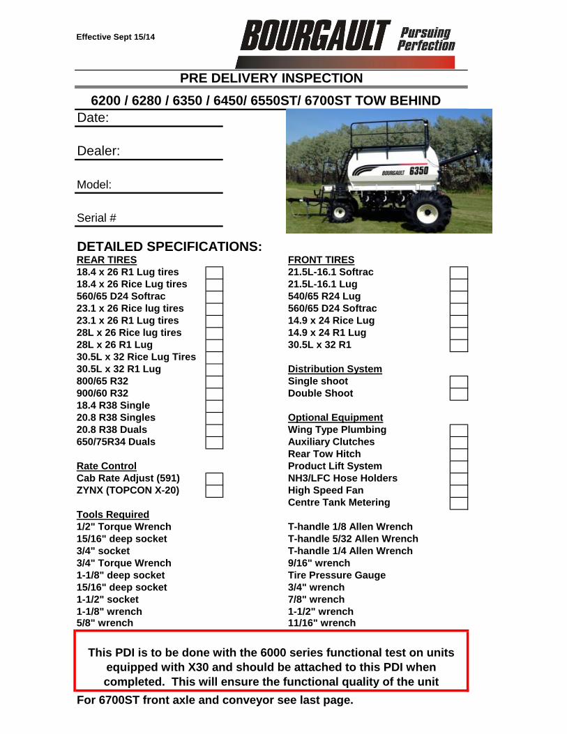
Effective Sept 15/14 Date: Dealer: Model: Serial # DETAILED SPECIFICATIONS: REAR TIRES 18.4 x 26 R1 Lug tires 21.5L-16.1 Softrac 18.4 x 26 Rice Lug tires 21.5L-16.1 Lug 560/65 D24 Softrac 540/65 R24 Lug 23.1 x 26 Rice lug tires 560/65 D24 Softrac 23.1 x 26 R1 Lug tires 14.9 x 24 Rice Lug 28L x 26 Rice lug tires 14.9 x 24 R1 Lug 28L x 26 R1 Lug 30.5L x 32 R1 30.5L x 32 Rice Lug Tires 30.5L x 32 R1 Lug 800/65 R32 Single shoot 900/60 R32 Double Shoot 18.4 R38 Single 20.8 R38 Singles Optional Equipment 20.8 R38 Duals Wing Type Plumbing 650/75R34 Duals Auxiliary Clutches Rear Tow Hitch Rate Control Product Lift System Cab Rate Adjust (591) NH3/LFC Hose Holders ZYNX (TOPCON X-20) High Speed Fan Centre Tank Metering T-handle 1/8 Allen Wrench 3/4" socket 3/4" wrench 1-1/2" socket 7/8" wrench 1-1/8" wrench 1-1/2" wrench 5/8" wrench 11/16" wrench For 6700ST front axle and conveyor see last page. Tools Required PRE DELIVERY INSPECTION FRONT TIRES 6200 / 6280 / 6350 / 6450/ 6550ST/ 6700ST TOW BEHIND Distribution System This PDI is to be done with the 6000 series functional test on units equipped with X30 and should be attached to this PDI when completed. This will ensure the functional quality of the unit 1-1/8" deep socket 15/16" deep socket 3/4" Torque Wrench 1/2" Torque Wrench 15/16" deep socket Tire Pressure Gauge T-handle 5/32 Allen Wrench 9/16" wrench T-handle 1/4 Allen Wrench
Transcript of DETAILED SPECIFICATIONS - Bourgault · DETAILED SPECIFICATIONS: ... Calibration motor is mounted...
Effective Sept 15/14
Date:
Dealer:
Model:
Serial #
DETAILED SPECIFICATIONS:REAR TIRES
18.4 x 26 R1 Lug tires 21.5L-16.1 Softrac
18.4 x 26 Rice Lug tires 21.5L-16.1 Lug
560/65 D24 Softrac 540/65 R24 Lug
23.1 x 26 Rice lug tires 560/65 D24 Softrac
23.1 x 26 R1 Lug tires 14.9 x 24 Rice Lug
28L x 26 Rice lug tires 14.9 x 24 R1 Lug
28L x 26 R1 Lug 30.5L x 32 R1
30.5L x 32 Rice Lug Tires
30.5L x 32 R1 Lug
800/65 R32 Single shoot
900/60 R32 Double Shoot
18.4 R38 Single
20.8 R38 Singles Optional Equipment
20.8 R38 Duals Wing Type Plumbing
650/75R34 Duals Auxiliary Clutches
Rear Tow Hitch
Rate Control Product Lift System
Cab Rate Adjust (591) NH3/LFC Hose Holders
ZYNX (TOPCON X-20) High Speed Fan
Centre Tank Metering
T-handle 1/8 Allen Wrench
3/4" socket
3/4" wrench
1-1/2" socket 7/8" wrench
1-1/8" wrench 1-1/2" wrench5/8" wrench 11/16" wrench
For 6700ST front axle and conveyor see last page.
Tools Required
PRE DELIVERY INSPECTION
FRONT TIRES
6200 / 6280 / 6350 / 6450/ 6550ST/ 6700ST TOW BEHIND
Distribution System
This PDI is to be done with the 6000 series functional test on units
equipped with X30 and should be attached to this PDI when
completed. This will ensure the functional quality of the unit
1-1/8" deep socket
15/16" deep socket
3/4" Torque Wrench
1/2" Torque Wrench
15/16" deep socket
Tire Pressure Gauge
T-handle 5/32 Allen Wrench
9/16" wrench
T-handle 1/4 Allen Wrench

Section 1 - Tires
Record values in allotted space for appropriate machine and tire size
6200 L6200Left Right
Size Pressure PSI Ft-LBS PSI Ft-LBS Torque (+/-25) Pressure Torque (+/-25)
Front Tires 14.9L x 24 N/A
21.5L-16.1 SL
Rear Tires 18.4 x 26
23.1 x 26
6280 L6280
Left Right
Size Pressure PSI Ft-LBS PSI Ft-LBS Torque (+/-25) Pressure Torque (+/-25)
Front Tires 21.5L-16.1 SL N/A
540/65 R24
Rear Tires 20.8 R38
18.4 R38
28L x 26
23.1 x 26
30.5L x 32
480/80R38
520/85R38
6350 L6350
Left Right
Size Pressure PSI Ft-LBS PSI Ft-LBS Torque (+/-25) Pressure Torque (+/-25)
Front Tires 21.5L-16.1 SL N/A
540/65 R24
Rear Tires 20.8 R38
30.5L x 32
28L x 26
520/85R38
800/65 R32
6550 L6550
Left Right
Size Pressure PSI Ft-LBS PSI Ft-LBS Torque (+/-25) Pressure Torque (+/-25)
Front Tires 540/65 R24 N/A
Rear Tires 900/60 R32
650/75 R34(dual)
6450 L6450
Left Right
Size Pressure PSI Ft-LBS PSI Ft-LBS Torque (+/-25) Pressure Torque (+/-25)
Front Tires 21.5L-16.1 SL N/A
540/65 R24
Rear Tires 900/60 R32
30.5L x 32
650/75 R34(dual)
6700
Left Right
Size Pressure PSI Ft-LBS PSI Ft-LBS Torque (+/-25)
Front Tires 30.5L x 32
Rear Tires 650/75 R34(dual)
Tires
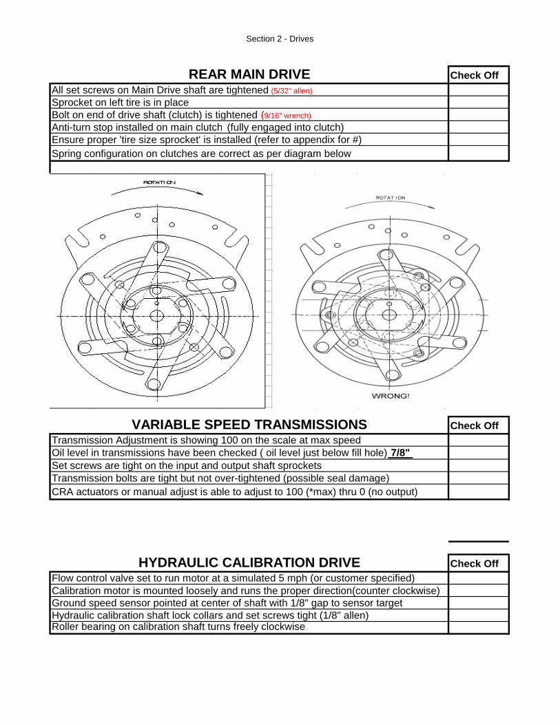
Section 2 - Drives
Check Off
All set screws on Main Drive shaft are tightened (5/32" allen)
Sprocket on left tire is in place
Bolt on end of drive shaft (clutch) is tightened (9/16" wrench)
Anti-turn stop installed on main clutch (fully engaged into clutch)
Ensure proper 'tire size sprocket' is installed (refer to appendix for #)
Spring configuration on clutches are correct as per diagram below
Check Off
Transmission bolts are tight but not over-tightened (possible seal damage)
Check Off
Calibration motor is mounted loosely and runs the proper direction(counter clockwise)
REAR MAIN DRIVE
Transmission Adjustment is showing 100 on the scale at max speed
Oil level in transmissions have been checked ( oil level just below fill hole) 7/8"
Set screws are tight on the input and output shaft sprockets
Roller bearing on calibration shaft turns freely clockwise
HYDRAULIC CALIBRATION DRIVEFlow control valve set to run motor at a simulated 5 mph (or customer specified)
Ground speed sensor pointed at center of shaft with 1/8" gap to sensor target
Hydraulic calibration shaft lock collars and set screws tight (1/8" allen)
VARIABLE SPEED TRANSMISSIONS
CRA actuators or manual adjust is able to adjust to 100 (*max) thru 0 (no output)

Section 3 - Metering
Check Off
Check Off
Anti-turn stoppers are installed on clutches (if equipped with auxilary clutches)
Ratcheting Clutch has been greased (1 shot each clutch)
METERING AUGERSLock collars and set screws on metering augers are tight (1/8" allen)
All grease nipples on metering augers are in place and greased
Absolutely no rubbing of flighting inside auger housing
Ensure that metering augers are in the proper tanks when matched with the
order sheet
Centerline of sensor intersects the centerline of the shaft within ± 1/4"
Sensor gap distance between sensor and sprocket teeth is 0.030" - 0.060"
for 591 or 1/32" - 1/8" for Topcon.
Centerline of the sensor is centered axially with the sprocket teeth (591) or
magnet assembly (Topcon) within ± 1/16"
METERING DRIVES
Angle drive gearboxes have 2oz of oil (see decal 3904-01-01)
All set screws on Drive shaft are tightened (3/16" allen)
All set screws on gear box shafts are tightened (5/32" allen)
Chains are running straight and quietly (use calibration motor to test)
Ensure proper implement sizing sprocket is installed (refer to appendix for #)
Drive shaft is aligned with gearboxes for smooth operation
Slip clutch on the end of the metering auger is greased

Section 4 - Hydraulics & Lift
Check Off
Check Off
Lift system lifts/lowers smoothly and at an acceptable speed
Lock pin engages/disengages easily
Doors on both sides of crate open/close easily
Calibration box retainer functions properly
Rubber bumpers ( x 2) are installed on tank side of crate.
Hydraulic ball valve on main fan functions properly - when the valve is in the off
position the fan is off
All fasteners on fan mount(s) are tight
Hydraulic hoses are not kinked or too tight
Higher Output Fan Motor - 1/2" hyd male couplers & caps at front of hitch have
been replaced with 1/2x3/4" adapters, 3/4" male couplers & 3/4" caps (hi speed
fan pictured below)
Case drain sensor installed on main fan - all electric and hydraulic connections
tight
Case drain line is not pinched off anywhere restricting oil flow
Hydraulic hose holder installed on fan(s) to support hoses and fittings
Identification tags are attached to front of hoses - fan 1, fan 2, case drain
LIFT SYSTEM (Optional)
Hydraulic on/off ball valve for calibration functions properly - when the valve is in
the on position the calibration motor is running
Hydraulic selector valve for the L/U auger functions properly - with the selector
valve in the in position the blower should operate and in the out position the
auger will function
Hydraulic hoses do not rub on sharp edges, or interfere with moving parts
HYDRAULICS
Two selector valves in place for double fan - one valve for single fan
All hoses are routed neatly
Hose holder installed on right side of hitch and hoses in storage position
All fittings are tight and free of leaks
Handrail folds properly for unloading at tank top

10 INCH / DELUXE LOAD/UNLOAD AUGER Check Off
Downspout is cut to the proper length - 43 ribs
All 3 cylinders function properly
All hydraulics are hooked up properly, are tight and are routed neatly
Supply connection to manifold is on the bottom - see picture below.
All fasteners are tightened
Auger swings freely and hydraulic hoses do not limit the auger movement
Transport lock is in place and is not too difficult to engage/disengage
Transfer hopper locks are properly set
L/U auger hydraulic hoses are routed correctly and looped according to photo below.
L/U auger arm is greased.
All paint damage fixed on L/U assembly (Pivot Arms, Saddle Arm, linkage threads, etc)
Angle drive is greased
L/U auger manifold hydraulic line layout Please ensure that hose loop is tied up
to replicate photo.
Check Off
Hopper is square to the seeder and pins in all locations
Auger is greased
Control and selector valves move freely and control rod threads are painted
Checked that all fasteners are tight on selector rod and handles
Control Lever must be perpendicular to auger in neutral position
All hydraulics are hooked up properly and are tightened (no leaks)
(standard equipment on 6550ST/ optional on 6450)
STANDARD LOAD/UNLOAD AUGER (8" or 10")Down spout installed and cut to the proper length
6200 - 47 ribs, 6280 - 39 ribs, 6350 - 33 ribs, 6450 - 26 ribs
Wire helix is trimmed back enough on downspout, to prevent paint damage on tank top
Transport locks are in place
Suggested Completion Time = 20 min.
Signature:_________________________
__________
Actual Time
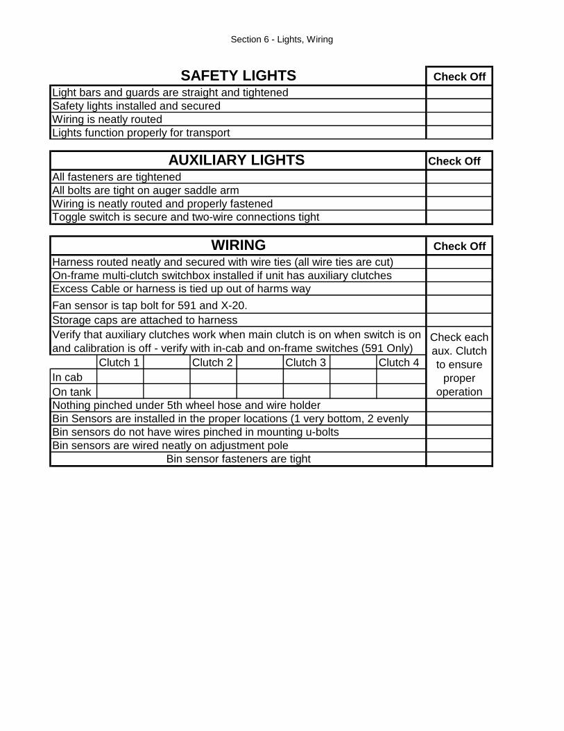
Section 6 - Lights, Wiring
Check Off
Light bars and guards are straight and tightened
Safety lights installed and secured
Wiring is neatly routed
Lights function properly for transport
Check Off
All fasteners are tightened
All bolts are tight on auger saddle arm
Wiring is neatly routed and properly fastened
Toggle switch is secure and two-wire connections tight
Check Off
Harness routed neatly and secured with wire ties (all wire ties are cut)
On-frame multi-clutch switchbox installed if unit has auxiliary clutches
Clutch 1 Clutch 2 Clutch 3 Clutch 4
In cab
On tank
SAFETY LIGHTS
AUXILIARY LIGHTS
WIRING
Verify that auxiliary clutches work when main clutch is on when switch is on
and calibration is off - verify with in-cab and on-frame switches (591 Only)
Excess Cable or harness is tied up out of harms way
Storage caps are attached to harness
Fan sensor is tap bolt for 591 and X-20.
Bin sensors do not have wires pinched in mounting u-bolts
Bin sensors are wired neatly on adjustment pole
Bin sensor fasteners are tight
Check each
aux. Clutch
to ensure
proper
operation
Bin Sensors are installed in the proper locations (1 very bottom, 2 evenly
Nothing pinched under 5th wheel hose and wire holder

Section 7 - Lids & Ladders
Check Off
Figure Y - Lid Assembly Breakdown
Check Off
Folding ladders are easy to fold and unfold
Working lights wiring does not get pinched when folding handrails
Broom doesn't interfere with handrails when they are folded down
All ladder bolts are tight
Plastic caps are installed in tubing ends of the folding ladders
TANK LIDS
Lid hinge stopper bolts installed (1/4" bolts, see Fig. Y)
Lid handle lock hooks protrude past lock tabs by at least 1/8" (See Fig. X)
Rubber handles are attached
Lid flange is installed with gasket underneath
Lid flange fasteners are tight
Lid seals have been installed straight and mesh well in the corners
Lid hinge bolts are tight, and lid pivots freely in bushing
Lid lock engages both lid lock tabs evenly
Lock tab bolts are tightened to 50 ft.lbs ± 10
Ensure that all bolts on the lids are tight
All top handrail sections fold up & down freely and are easy to return to
upright working position
CATWALKS & LADDERS

Section 8 - Unibody
Check Off
Unidbody/Running Gear (6200 - 6550ST)Check for gap between plates on 5th wheel assembly (1/16" or less)
Rotate (steering motion) 5th wheel to make sure not too tight
Ensure that front axle pivot bolt is tight (no slop) (see Fig X)
Figure Y - Axle Stub Connection
Grease 5th Wheel (10 shots)
Check torques on axle stub bolts (3/4" 200 ft-lb, 1" 480 ft-lb; see Fig Y)
Figure W - 5th Wheel Assembly
Figure X - Front Axle
Suggested Completion Time = 10 min
Signature:________________________________________
_________
Actual Time

Section 9 - Pressurization
Check Off Check Off
Check Off Check Off
All clamps are tight
All dents in pipes < 1/8"
Main pipes are in line with the fan and parallel to each other
Main pipes are parallel when looking at them from the side of the machine
Calibration hose clamps are complete with hair pins
Calibration Tubes are installed - one per metering auger
U-bolts hanging main pipes under 5th wheel are tight
Check Off
Hose clamps on pressurization lines are tight (see fig x)
CHECK OFF
Intertank connect doors are installed and tight (see fig x)
DISTRIBUTION SYSTEM
TANK COMPARTMENTS
CALIBRATION TOOLSCorrect amount of boxes included with tank (1 per metering auger, Fig X)
Storage container attached in-between transmissions
Weight of calibration boxes all within ± 0.2 lbs (as stamped on each box)
Cal. Box lock pin installed and operates properly
Figure X - Calibration Boxes
PRESSURE TEST
No leaks from fan to all transfer line connections
Use the procedure on the following page to test for individual
tank pressurization. This is very important
Fan turns in correct direction (clockwise looking into the fan inlet)
Fan run up to 4000 rpm (as shown on monitor)
Figure X - Intertank Door
Figure X - Pressurization Line Figure X - Bin Level Sensors


Section 11 - Final Inspection
CHECK OFF
Grease line is installed with zerks (2010-56) & greased
Tie rods & jam nuts are installed and tightened to proper tow in ( picture at bottom of page)
Hitch jack turns easily by hand
Distribution line holder on hitch installed with fastener tight
Correct Safety Chain (60000lb min) and Tag attached to the hitch
Ensure quantity 2 - 5/16 bolts are tight on hitch pull pin
Easy Hitch functions properly and can be easily moved
Easy hitch pin installed along with lynch pin
Hitch hinge cotter pins and washers installed
All paint damage repaired
CHECK OFF
Check for paint damage and touch-up if required.
Chains for Single Metering Augers are placed in high range, double augers in low range
All sensors working correctly: shaft, bin level, fan, and ground speed sensors
Monitor turned off for 10 seconds and turned back on and still functions (3 times) - 591 Only
Monitor programmed and has learned the correct sensors (as per Oper. Man.) - 591 Only
Front Axle & Hitch (6700ST only)
Actuators are returned to zero and then extended 1/2" - 591 Only
Unit is free of Hydraulic leaks
Colored wire ties have been installed on harnesses - 591 Only
Unit is washed
Front tires installed with all wheel nuts
Ensure the front hitch is perpendicular "90 degrees" to the front axle
FINAL INSPECTION
Clutch harness to clutch; Monitor harness to Monitor(ends are marked) - 591 Only
To measure the toe in measure the front and back of tires from centre to centre (ensuring that measurement is taken at same height front to back). The front should measure 0" - 1.5" narrower than the rear side. Also ensure that the turnbuckles on the front side of the axle measure the same from pin to pin.
Axle Turnbuckle.
Suggested Completion Time = 45 min
Signature:________________________________________
_________
Actual Time

Check Off
10 INCH CONVEYOR (6700ST Only)All cotter pins are installed in cylinder pins after final adjustments are made
Transport lock is in place
All 4 cylinders function properly
Transport lock is in place and transfer hopper locks are properly set
L/U auger arm is greased
All hydraulics are hooked up properly, are tight and are routed neatly
All fasteners are tightened
Auger swings freely and hydraulic hoses do not limit the auger movement
Front support is not too difficult to engage/disengage

Appendix
TIRE SIZING SPROCKET REAR TIRE SIZE
2810-90 DRV SPRKT 40A35 2.641 ID PNTD 28LX26 AWT
2810-88 DRV SPRKT 40A34 2.641 ID PNTD 28LX26 DT2 R1 LUG, 28LX26 TD8 R2 RICE
23.1X26 DT2 R1 LUG, 23.1X26 TD8 R2 RICE
2810-77 DRV SPRKT 40A31 2.641 ID PNTD 800/65R32 172A8 R1W
2810-76 DRV SPRKT 40A30 2.641 ID PNTD 20.8R38 RDL R2 SGL
2811-07 DRV SPRKT 40A40 2.641 ID PNT 18.4X26 AWT
2811-01 DRV SPRKT 40A38 2.641 ID PNTD 18.4X26 R1 DT2 LUG
2810-99 DRV SPRKT 40A37 2.641 ID PNTD 18.4X26 TD8 R2 RICE, 23.1X26 AWT
2811-22 DRV SPRKT 40A43 2.641 ID PNTD 560/65D24 SOFTR
2810-76 DRV SPRKT 40A30 2.641 ID PNTD 650 duals
IMPLEMENT SIZING SPROCKET IMPLEMENT WIDTH
2813-97 SPROCKET SLTD 40A24 23½’ - 24’5”
2814-35 SPROCKET SLTD 40A25 24½’ - 25’5”
2814-03 SPROCKET SLTD 40A28 27½’ - 28’5”
2814-04 SPROCKET SLTD 40A29 28½’ - 29’5”
2814-05 SPROCKET SLTD 40A30 29½’ - 30’5”
2814-06 SPROCKET SLTD 40A32 31½’ - 32’5”
2814-07 SPROCKET SLTD 40A33 32½’ - 33’5”
2814-08 SPROCKET SLTD 40A34 33½’ - 34’5”
2814-44 SPROCKET SLTD 40A35 34½’ - 35’5”
2814-47 SPROCKET SLTD 40A36 35½’ - 36’5”
2814-11 SPROCKET SLTD 40A39 38½’ - 39’5”
2814-12 SPROCKET SLTD 40A40 39½’ - 40’5”
2814-49 SPROCKET SLTD 40A41 40½’ - 41’5”
2814-13 SPROCKET SLTD 40A42 41½’ - 42’5”
2814-16 SPROCKET SLTD 40A45 44½’ - 45’5”
2814-17 SPROCKET SLTD 40A46 45½’ - 46’5”
2814-18 SPROCKET SLTD 40A47 46½’ - 47’5”
2814-19 SPROCKET SLTD 40A48 47½’ - 48’5”
2814-20 SPROCKET SLTD 40A50 49½’ - 50’11”
2814-22 SPROCKET SLTD 40A52 51’ - 52’11”
2814-50 SPROCKET SLTD 40A54 53’ - 54’11”
2814-23 SPROCKET SLTD 40A56 55’ - 56’11”
2814-24 SPROCKET SLTD 40A58 57’ - 58’5”
2814-25 SPROCKET SLTD 40A59 58½’ - 60’5”
2814-30 SPROCKET SLTD 40A62 60½’ - 62’11”
2814-26 SPROCKET SLTD 40A64 63’ - 64’5”
2814-28 SPRKT SLTD 40A70 69'3" - 70'2"
2814-27 SPRKT SLTD 40A74 73'6"
TOOLS REQUIRED:
Allen Wrenches 1/8", 5/32", 3/16", 1/4"
Flat wrenches 1/2', 9/16"
Torque Wrench 1 1/16", 1 1/2 "
Tape Measure
Tire guage
Feeler guages