DETAILED PROJECT REPORT FOR INSTALLATION OF 45 KLPD...
100
DETAILED PROJECT REPORT FOR INSTALLATION OF 45 KLPD GRAIN BASED DISTILLERY PLANT FOR PRODUCTION OF RECTIFIED SPIRIT OR EXTRA NEUTRAL ALCOHOL WITH STILLAGE EVAPORATION PLANT, DRYER, EFFLUENT TREATMENT PLANT, AND BOILER (18MT/Hr) WITH TG (1.5MW) SET TO ACHIEVE ZERO LIQUID DISCHARGE (ZLD) --------------------------------------------------------- VITTHALRAO SHINDE SAHAKARI SAKHAR KARKHANA LTD., GANGAMAINAGAR, PIMPALNER, TAL. MADHA, DIST. SOLAPUR (M.S.) PHONE NO. 02183-233056, 233075, 233076 FAX NO. 02183-233005 [email protected] Prepared By- VASANTDADA SUGAR INSTITUTE Manjari (Bk), Pune- 412 307; Maharashtra. Phone – (020) 26902100, Fax – (020) 26902244 E-mail : [email protected] Visit us at : www.vsisugar.com MAY- 2017
Transcript of DETAILED PROJECT REPORT FOR INSTALLATION OF 45 KLPD...
DETAILED PROJECT REPORT
FOR
INSTALLATION OF
45 KLPD GRAIN BASED DISTILLERY PLANT
FOR PRODUCTION OF
RECTIFIED SPIRIT OR
EXTRA NEUTRAL ALCOHOL
WITH
STILLAGE EVAPORATION PLANT,
DRYER,
EFFLUENT TREATMENT PLANT,
AND BOILER (18MT/Hr) WITH TG (1.5MW) SET
TO
ACHIEVE ZERO LIQUID DISCHARGE (ZLD)
---------------------------------------------------------
VITTHALRAO SHINDE SAHAKARI SAKHAR
KARKHANA LTD., GANGAMAINAGAR, PIMPALNER,
TAL. MADHA, DIST. SOLAPUR (M.S.)
PHONE NO. 02183-233056, 233075, 233076 FAX NO. 02183-233005
Prepared By-
VASANTDADA SUGAR INSTITUTE
Manjari (Bk), Pune- 412 307; Maharashtra.
Phone – (020) 26902100, Fax – (020) 26902244
E-mail : [email protected] Visit us at : www.vsisugar.com
MAY- 2017

A C K N O W L E D G E M E N T
The Director General and the staff of Department of Alcohol Technology,
Vasantdada Sugar Institute, Pune express their sincere gratitude and thanks to Hon‟ble
Founder Chairman, Shri. Babanrao Vitthalrao Shinde (MLA), Vice Chairman,
Shri. Pandurang Anna Patil, Managing Director, Shri. R. S. Ranaware & the Board of
Directors of M/s. Vitthalrao Shinde Sahakari Sakhar Karkhana Ltd., Gangamainagar,
Post. Pimpalner, Tal. Madha, Dist. Solapur for assigning the work of preparation of
Detailed Project Report for 45 KLPD grain based distillery plant to produce rectified
spirit or Extra Neutral Alcohol, alongwith stillage evaporation system to achieve “Zero
Liquid Discharge”, as well as for installation of boiler (18MT/hr,@45 Kg/cm2) &
1.50MW TG set.
We are also thankful to the Secretary, Shri. S. M. Khadsare, Chief Engineer,
Shri. C. S. Bogade, Chief Chemist, Shri. P. S. Yelpale, Chief Agriculture Officer, Shri. S.
P. Thite, Chief Accountant, Shri. B. N. Jagdale, Distillery Manager, Shri. P. V. Bagal and
other technical staff of M/s. Vitthalrao Shinde Sahakari Sakhar Karkhana Ltd.,
Gangamainagar, Post. Pimpalner, Tal. Madha, Dist. Solapur, for their valuable assistance
in collection of technical data from the sugar mill, which was necessary for preparing this
Detailed Project Report.
(Dr. S. V. Patil)
Technical Adviser and Head,
Department of Alcohol Technology,
Vasantdada Sugar Institute,
Manjari (BK), Pune-412307.
Date: May 2017
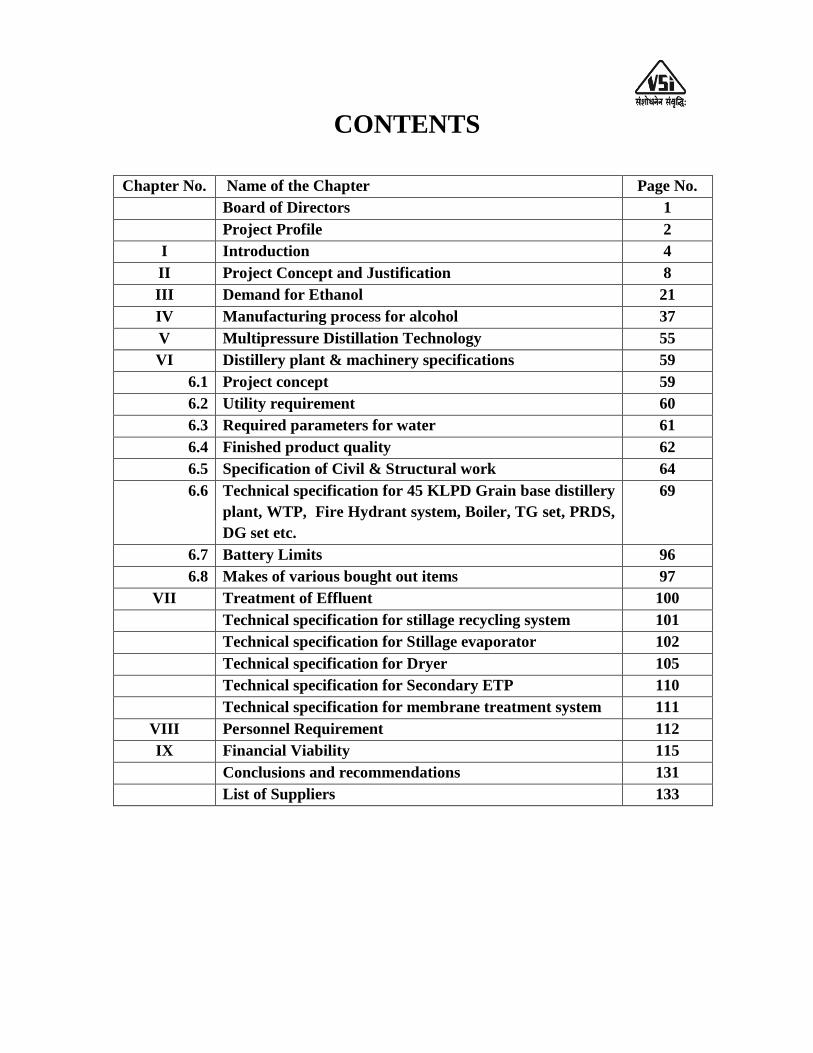
CONTENTS
Chapter No. Name of the Chapter Page No.
Board of Directors 1
Project Profile 2
I Introduction 4
II Project Concept and Justification 8
III Demand for Ethanol 21
IV Manufacturing process for alcohol 37
V Multipressure Distillation Technology 55
VI Distillery plant & machinery specifications 59
6.1 Project concept 59
6.2 Utility requirement 60
6.3 Required parameters for water 61
6.4 Finished product quality 62
6.5 Specification of Civil & Structural work 64
6.6 Technical specification for 45 KLPD Grain base distillery
plant, WTP, Fire Hydrant system, Boiler, TG set, PRDS,
DG set etc.
69
6.7 Battery Limits 96
6.8 Makes of various bought out items 97
VII Treatment of Effluent 100
Technical specification for stillage recycling system 101
Technical specification for Stillage evaporator 102
Technical specification for Dryer 105
Technical specification for Secondary ETP 110
Technical specification for membrane treatment system 111
VIII Personnel Requirement 112
IX Financial Viability 115
Conclusions and recommendations 131
List of Suppliers 133
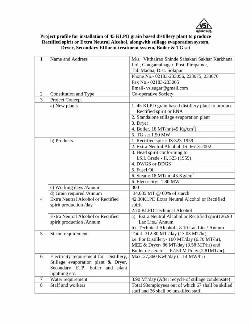
Project profile for installation of 45 KLPD grain based distillery plant to produce
Rectified spirit or Extra Neutral Alcohol, alongwith stillage evaporation system,
Dryer, Secondary Effluent treatment system, Boiler & TG set
1 Name and Address M/s. Vitthalrao Shinde Sahakari Sakhar Karkhana
Ltd., Gangamainagar, Post. Pimpalner,
Tal. Madha, Dist. Solapur
Phone No.- 02183-233056, 233075, 233076
Fax No.- 02183-233005
Email- [email protected]
2 Constitution and Type Co-operative Society
3 Project Concept
a) New plants 1. 45 KLPD grain based distillery plant to produce
Rectified spirit or ENA
2. Standalone stillage evaporation plant
3. Dryer
4. Boiler, 18 MT/hr (45 Kg/cm2)
5. TG set 1.50 MW
b) Products 1. Rectified spirit: IS:323-1959
2. Extra Neutral Alcohol: IS: 6613-2002
3. Head spirit conforming to
I.S.I. Grade - II, 323 (1959)
4. DWGS or DDGS
5. Fusel Oil
6. Steam: 18 MT/hr, 45 Kg/cm2
6. Electricity: 1.80 MW
c) Working days /Annum 300
d) Grain required /Annum 34,085 MT @ 60% of starch
4 Extra Neutral Alcohol or Rectified
spirit production /day
42.30KLPD Extra Neutral Alcohol or Rectified
spirit
2.70 KLPD Technical Alcohol
Extra Neutral Alcohol or Rectified
spirit production /Annum
a) Extra Neutral Alcohol or Rectified spirit126.90
Lac Lits./ Annum
b) Technical Alcohol - 8.10 Lac Lits./ Annum
5 Steam requirement Total- 312.80 MT /day (13.03 MT/hr),
i.e. For Distillery- 160 MT/day (6.70 MT/hr),
MEE & Dryer- 86 MT/day (3.58 MT/hr) and
Boiler de-aerator – 67.50 MT/day (2.81MT/hr).
6 Electricity requirement for Distillery,
Stillage evaporation plant & Dryer,
Secondary ETP, boiler and plant
lightning etc.
Max. 27,360 Kwh/day (1.14 MW/hr)
7 Water requirement 3.90 M3/day (After recycle of stillage condensate)
8 Staff and workers Total 93employees out of which 67 shall be skilled
staff and 26 shall be unskilled staff.
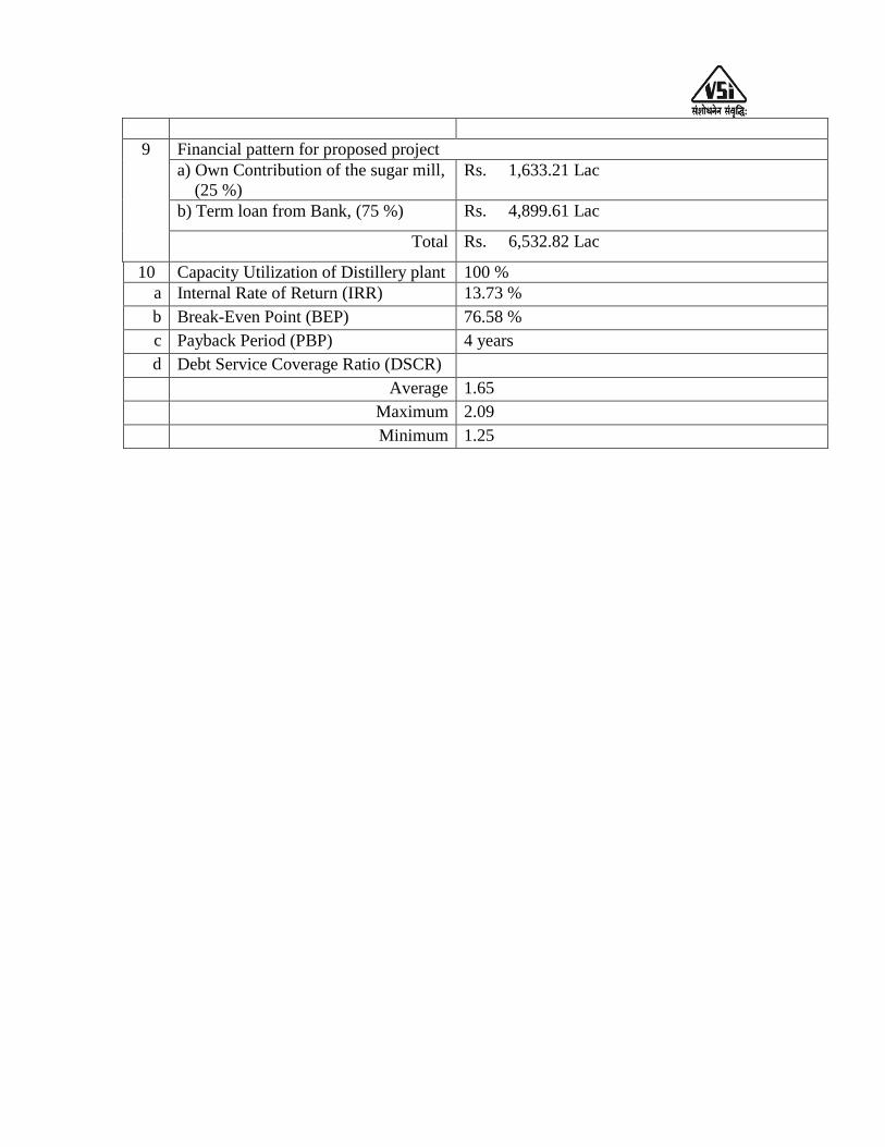
9 Financial pattern for proposed project
a) Own Contribution of the sugar mill,
(25 %)
Rs. 1,633.21 Lac
b) Term loan from Bank, (75 %) Rs. 4,899.61 Lac
Total Rs. 6,532.82 Lac
10 Capacity Utilization of Distillery plant 100 %
a Internal Rate of Return (IRR) 13.73 %
b Break-Even Point (BEP) 76.58 %
c Payback Period (PBP) 4 years
d Debt Service Coverage Ratio (DSCR)
Average 1.65
Maximum 2.09
Minimum 1.25

Vitthalrao Shinde Sahakari Sakhar Karkhana Ltd.,
Gangamainagar, Post. Pimpalner,
Tal. Madha, Dist. Solapur
BOARD OF DIRECTORS
Sr. No. Name Designation
1 Hon. Shri. BabanraoVitthalrao Shinde (M.L.A.) Founder Chairman
2 Shri. Pandurang Anna Patil Vice Chairman
3 Shri. Maruti Vishwanath Bagal Director
4 Shri. Nilkanth Bhagwan Patil Director
5 Shri. Sitaram Limbraj Gaikawad Director
6 Shri. Prabhakar Gangadhar Kute Director
7 Shri. Baban Pandurang Patil Director
8 Shri. Ramesh Venkyatrao Yewale Director
9 Shri. Bhaurao Bhanudas Tarange Director
10 Shri. Vishnu Mahadeo Humbe Director
11 Shri. Shivaji Mahadeo Doke Director
12 Shri. Popat Digambar Gaikawad Director
13 Shri. Amol Saudagar Chavan Director
14 Shri. Ranjitsinh Babanrao Shinde Director
15 Shri. Vetala Jalindhar Jadhav Director
16 Shri. Gautam Maruti More Director
17 Shri. Laxman Ramdas Khupase Director
18 Shri. Balasaheb Annasaheb Dhavale Director
19 Sau. Nandatai Baburao Surve Director
20 Sau. Sindhutai Subhash Nagtilak Director
21 Shri. Vamanrao Pralhad Ubale Director
22 Shri. Popat Balbhim Chavan Director
23 Shri. Ramchandra Dhula Takale Director
24 Shri. Rajendrakumar Suryakant Ranaware Managing Director
CHAPTER - I: INTRODUCTION
Vitthalrao Shinde Sahakari Sakhar Karkhana Limited, is located about 7 kms
away from Mumbai- Hyderabad National Highway No. 65 at Gangamainagar, Post
Pimpalner, Tal. Madha, Dist. Solapur. Nearest railway station is Kurduwadi. The sugar
mill (VSSSKL) is registered as a Co-Operative Society vide Registration No.
SUR/MADH/PRG/(A), S90/1999 dated 21/05/1999. It is one of the progressive sugar
mill in the Solapur district and has achieved excellent results since its establishment. The
sugar mill has achieved best technical performance and expanded its capacity in short
time span under the able guidance of Founder Chairman Hon. Shri. Babanrao Vitthalrao
Shinde (MLA).
The initial installed crushing capacity of the sugar mill was 2500 TCD & the first
crushing season was conducted in the year 2001-02. Based on increasing availability of
sugarcane in area of operation, the sugar mill has expanded its crushing capacity from
2,500 TCD to 3,500 TCD in 2007-08, from 3,500 TCD to 6,000 TCD in 2011-12 and
from 6,000 TCD to 12,500 TCD in 2013-14. VSSSKL has also installed a 49 MW
co-generation plant.
The present capacity of the sugar mill is 12,500 TCD. During the season 2015-
2016, the factory operated for 137 days and crushed 16.07 Lac MT of sugarcane with an
average daily crushing of 11,767 MT of sugarcane (including stoppages). Since, the
season 2015-2016 was the drought year, the sugarcane availability to sugar mill was less
and accordingly, the average cane crush was low. However, during the month of
December, 2015, the factory has crushed 3,92,076 MT of sugarcane in 31 days, resulting
in a daily cane crush rate of 12,648 MT (including stoppages).
The last five years performance of sugar mill and future five years expected
technical performance of the sugar mill is given in table 1.1 & 1.2.
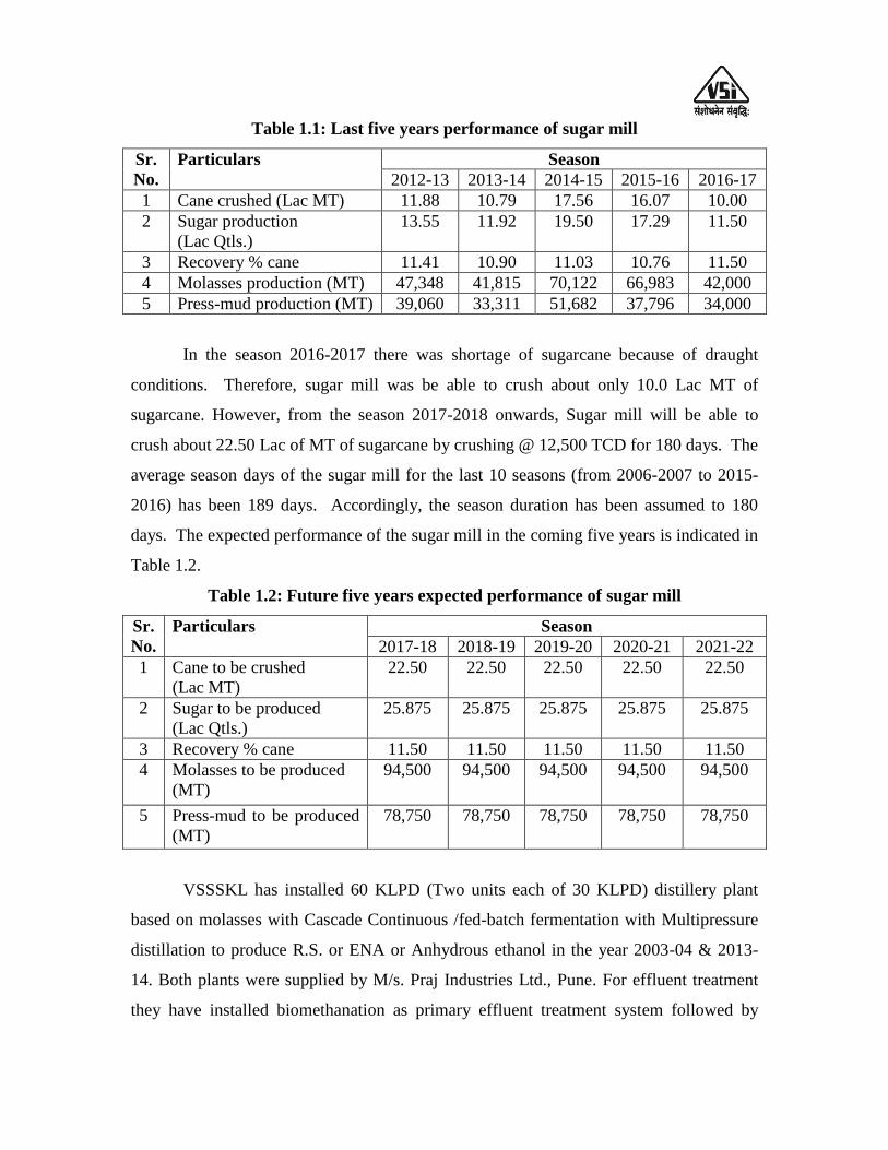
Table 1.1: Last five years performance of sugar mill
Sr.
No.
Particulars Season
2012-13 2013-14 2014-15 2015-16 2016-17
1 Cane crushed (Lac MT) 11.88 10.79 17.56 16.07 10.00
2 Sugar production
(Lac Qtls.)
13.55 11.92 19.50 17.29 11.50
3 Recovery % cane 11.41 10.90 11.03 10.76 11.50
4 Molasses production (MT) 47,348 41,815 70,122 66,983 42,000
5 Press-mud production (MT) 39,060 33,311 51,682 37,796 34,000
In the season 2016-2017 there was shortage of sugarcane because of draught
conditions. Therefore, sugar mill was be able to crush about only 10.0 Lac MT of
sugarcane. However, from the season 2017-2018 onwards, Sugar mill will be able to
crush about 22.50 Lac of MT of sugarcane by crushing @ 12,500 TCD for 180 days. The
average season days of the sugar mill for the last 10 seasons (from 2006-2007 to 2015-
2016) has been 189 days. Accordingly, the season duration has been assumed to 180
days. The expected performance of the sugar mill in the coming five years is indicated in
Table 1.2.
Table 1.2: Future five years expected performance of sugar mill
Sr.
No.
Particulars Season
2017-18 2018-19 2019-20 2020-21 2021-22
1 Cane to be crushed
(Lac MT)
22.50 22.50 22.50 22.50 22.50
2 Sugar to be produced
(Lac Qtls.)
25.875 25.875 25.875 25.875 25.875
3 Recovery % cane 11.50 11.50 11.50 11.50 11.50
4 Molasses to be produced
(MT)
94,500 94,500 94,500 94,500 94,500
5 Press-mud to be produced
(MT)
78,750 78,750 78,750 78,750 78,750
VSSSKL has installed 60 KLPD (Two units each of 30 KLPD) distillery plant
based on molasses with Cascade Continuous /fed-batch fermentation with Multipressure
distillation to produce R.S. or ENA or Anhydrous ethanol in the year 2003-04 & 2013-
14. Both plants were supplied by M/s. Praj Industries Ltd., Pune. For effluent treatment
they have installed biomethanation as primary effluent treatment system followed by

standalone multiple effect biomethanated spentwash evaporation as secondary effluent
treatment system followed by biocomposting as tertiary effluent treatment system to
achieve “Zero Spentwash Discharge” as per CPCB norms.
The performance of the both distillery plants is excellent. Both distillery plants
are now running smoothly. The average rectified spirit production of existing 60 KLPD
distillery plant for last three years is about 80 KLPD.
Last five years performance of the distillery plants and expected performance in
the future five years is given in the Table 1.3 & Table 1.4 respectively.
Table 1.3: Last five years performance of distillery plant
Sr.
No.
Particulars Years
2011-12 2012-13 2013-14 2014-15 2015-16
1 Total Alcohol Production
(Lac Lits./annum)
104.35 80.18 146.46 164.82 267.80
2 Total molasses
Consumption (MT)
37,945 29,156 57,481 60,834 1,00,090
Own molasses (MT) 55,689 47,348 41,815 70,122 66,983
Purchased molasses (MT) ---- ---- ---- ----- 33,107
3 Recovery of Rectified spirit
(Lits./MT)
275.00 275.00 254.79 270.93 267.52
4 Fermentation Efficiency
(%)
88.80 89.00 89.00 89.00 89.00
5 Distillation Efficiency (%) 98.32 98.45 98.23 98.32 98.40
6 Average working days /
Annum
303 223 195 203 281
7 Average alcohol production
(Lits./ day)
34,400 35,900 75,100 81,100 95,300
It can be seen from table 1.3 that the average production of alcohol from the year
2013-14 to 2015-16 was above 80 KLPD and recovery of Rectified spirit was about 270
liters/MT of molasses.
Table 1.4: Future five years expected performance distillery plant,
Sr.
No.
Particulars Years
2017-18 2018-19 2019-20 2020-21 2021-22
1 Average working days /
Annum
270 270 270 270 270
2 Total alcohol (R.S. + I.S.)
to be produced
216.00 216.00 216.00 216.00 216.00

(Lac Lits./annum)
4 Total molasses to be
consumed (MT)
80,000 80,000 80,000 80,000 80,000
5 Expected recovery of
Rectified spirit (Lits./MT)
270.0 270.0 270.0 270.0 270.0
6 Expected Fermentation
Efficiency (%)
90.00 90.00 90.00 90.00 90.00
7 Expected Distillation
Efficiency (%)
98.50 98.50 98.50 98.50 98.50
Socio Economic Activities: Apart from running the factory successfully and distributing
the profit to member farmers, the management of VSSSKL is also involved in several
Socio-Economic developmental activities for member farmers and workers. Some of the
activities are briefly mentioned below,
i) The sugar mill is giving medical aid to the employees and their dependents.
ii) The sugar mill helps member farmers by supplying fertilizers, cane seeds and
also arranges field demonstration & seminar to educate the farmers.
iii) Sugar mill provides financial support to implement lift irrigation schemes and
drip irrigation schemes in its area of operation.
iv) Sugar mill provides the residential facility for the staff members.
v) The labour welfare activities for workers are conducted at site.
vi) Sugar mill has arranged mass marriage program every year at factory site.
vii) The labour welfare activities for workers are conducted at site.
In short, the performance of existing 60 KLPD distillery plant of Vitthalrao
Shinde Sahakari Sakhar Karkhana Ltd., is very impressive. To exploit more benefit from
this industrial complex, the management of the sugar mill has decided to install 45 KLPD
grain based distillery plant, boiler & TG set, stillage evaporation plant, dryer and Effluent
treatment plant etc.
CHAPTER – II: PROJECT CONCEPT AND JUSTIFICATION
India is the largest producer of sugarcane as well as sugar in the world. The sugar
industry occupies a pride of place in rural economy. Most of the sugar industries are
located in rural areas providing employment to rural masses.
Justification for diversification to additional grain based distillery plant:
Due to increasing demand for alcohol in the country in the last few years and also
due to shortage of molasses, the prices of alcohol are increasing day by day. Potable
grade Rectified spirit (produced from molasses) price went up to almost Rs. 35.0 to 36.0
per liter. In the last two-three years the availability of alcohol has become very difficult.
The present basic price of molasses and extra neutral alcohol (produced from molasses) is
Rs. 5,000 to 5,500/MT and Rs. 40.00 to 42.00 /liter respectively. These prices are
expected to remain high in the coming years due to increasing demand for alcohol. It has
become difficult for liquor manufacturing units to purchase good quality alcohol from the
open market and run economically. Therefore, many potable alcohol and liquor-
manufacturing units are looking for alternate raw materials. One of the well established
routes to manufacture potable alcohol and liquors is to use grains as feedstock. Grain
alcohol and liquors made from grain alcohol have special value and can fetch higher price
in the market. Also it will be worthwhile to note that there are abnormal variations in the
price & availability of rectified spirit & molasses depending upon the availability of basic
raw material, i.e. sugar cane. There is also no assurance of good return for molasses
based rectified spirit. To fulfill this demand the management of has decided to establish a
new distillery unit based on grains as the feedstock to produce superior quality of potable
alcohol (Rectified spirit and Extra Neutral Alcohol).
Table 2.1: State wise grain based distilleries in India
Sr.
No.
State Category Based on Capacity Total Number
of Distilleries 0-50 KLPD
(Small)
50-100 KLPD
(Medium)
100 KLPD
and above
(Large)
1 Andhra Pradesh 02 09 04 15
2 Chhattisgarh 01 04 -- 05

3 Assam 01 01 -- 02
4 Haryana 04 05 03 12
5 Himachal Pradesh 02 -- -- 02
6 Karnataka 02 03 -- 05
7 Madhya Pradesh 01 06 01 08
8 Maharashtra 22 06 02 30
9 Punjab 04 05 07 16
10 Rajasthan 06 01 01 08
11 Uttar Pradesh 01 01 -- 02
12 West Bengal -- 01 -- 01
13 Jharkhand -- 01 -- 01
14 Sikkim -- 01 -- 01
15 Orissa 01 -- -- 01
16 Bihar 01 -- -- 01
Total 48 44 18 110
Total installed capacity based on 300 working days, Million Lits/Annum= 2062.20
Establishing proposed grain based distillery project will be benefit to the farming
community and surrounding environment due to following aspects:
Maize /Rice crop is grown in normal soil.
It grows in four months on rainwater
Corn & rice are the crops that can be grown by small & marginal farmers because it
does not need the infrastructure as in case of sugarcane.
Corn /rice based distillery effluent can be treated more efficiently to produce DWGS
or DDGS, which can be used as animal feed.
The corn/ rice -based distillery will be zero pollution distilleries.
Blackened or damaged rice can also be procured from market to produce alcohol.
It is expected that the farmers in the surrounding area will grow corn in addition to
conventional crops and supply it to the Vitthalrao Shinde S.S.K. Ltd.,
Rice, maize and other grains are one of the main course cereal crops of India.
India‟s market year 2015-16 rice ending stocks are estimated to be 18.50 million tonnes
(16.2 million government rice and 2.3 million tonnes private) due to higher procurement
and relatively weak off take, according to the FAS. Market year 2016-17 ending stocks

are also forecasted to be higher at 16.4 million tonnes on normal procurement and
government off take.
Maize is the third most important cereal crop in India after rice and wheat. It
accounts for 9% of total food grain production in the country. Karnataka, Rajasthan,
Andhra Pradesh, Maharashtra and Uttar Pradesh are the major maize producing states;
together contribute 60% of area and 70% of maize production in India. In India in 2015-
16, maize occupied 86.27 lakh ha area and production was estimated 13 percent low to
about 210.20 lakh tonnes (Third Advance Estimates dt. 9-5-2016) as against 92.71 lakh
ha and 241.7 lakh tonnes in previous year, respectively.
The production of major crops during 2015-16 in India is as follows:
Food grains:-
Rice – 103.61 million tonnes
Wheat – 93.82 million tonnes
Coarse Cereals – 38.40 million tonnes
Maize – 21.00 million tonnes
Pulses – 17.33 million tonnes
Tur – 2.55 million tonnes
Gram – 8.09 million tonnes
India is second largest producer of corn/rice in the world. This crop is ideally
suited for semi-arid agro climatic regions of the country and it gives reasonably good
yield with minimal requirement of irrigation and fertilizers. Since corn/rice must be
cultivated in semi-arid regions as fodder to feed the large cattle population of the country,
industrial applications for this grain are being explored so that corn/rice cultivation
becomes economically viable for small & marginal farmers. While the area under
corn/rice cultivation in India is consistently declining, the yield is increasing year by year
and thus the overall production of corn/rice is increasing.
Corn/rice is grown in the Kharif (Rainy season) and Rabi (Post rainy season) but
the share of Kharif is higher both in terms of area under cultivation & production. The
Kharif corn/rice crop accounts for 55% of the total area under cultivation and 68% of the
total production. Also the yield of Kharif season is much higher than Rabi. Produce of
Kharif season gets damaged to the extent of 20% and fetches a low price of Rs. 2500-
4,500 /M.T. as compared to Rs. 4,000-6,000 /M.T. for Rabi crop. One of the reasons for
low farm gate price for Kharif corn/rice is that there are several layers of traders between
farmer and consumer whereas Rabi crop has good demand and does not go through so
many layers of traders. Rabi crop is almost entirely used for human consumption whereas
Kharif crop is not very popular for human consumption and is largely used for animal
feed, starch and alcohol industry.
The consumption pattern of rice grains indicates that the demand for rice as food
would decrease, however the demand for Industrial use is set to increase due to
availability of sound technical knowledge & encouragement by Government. The major
industry sector consumers are Poultry sector (also replacing share of maize), Dairy sector,
Alcohol sector & Starch sector. Amongst these sectors alcohol industry is having the
largest share.
The major application of maize is animal feed, production of starch/starch
derivatives and ethanol production. Corn/rice grains fetches lower price when used for
animal feed and the quantity used for starch industry is very small. Therefore, use of rice
for production of Potable Alcohol would help the poor farmers because they will get a
good price for their produce.
Out of total stock 18.50 million MTs of corn/rice, about 2-3 million MT is wasted
due to grain blackening following un-seasonal rains. This grain is not suitable for human
or animal consumption. Hence, it is sold at a low price and thus gives lower returns to
the farmers. Thousands of the marginal farmers will be benefited if such grains can be
used for Potable alcohol production.
Rice has higher starch contents when compared with maize. Rice is the best suited
amongst all coarse grains for the production of alcohol because of higher yield as
compared with the industry average. The process for alcohol production using Corn or
rice is preferable as it is environment friendly compared to molasses. Use of Corn or rice
for alcohol/ethanol production will use up to 10-15% of the mold damaged grain, which
will help farmers to get a good price for their produce.
The proposed project mainly consists of following major sections:
1. Grain processing section
2. Distillery unit

3. Decantation
4. Stillage evaporation plant
5. Dryer
6. Secondary effluent treatment plant
7. Boiler
8. TG set etc.
While the current financial viability analysis is based upon selling the entire
products in India, the export market potential is also tremendous. The promoters may
consider entering export market at a later stage either on their own or with a suitable tie-
up with international partner for marketing.
Comparative advantages of grain-based distillery over molasses based distillery
are given in the following table 2.2.
Table 2.2: Comparison between Molasses and Grain based distilleries to produce
alcohol
Molasses based
Distillery to produce alcohol
Grain based
Distillery to produce alcohol
Pollution
Aspect
Molasses based distilleries are highly
polluting and are categorized as “Red” in
our country.
The norms for treatment of molasses
based distillery are becoming stringent
and therefore, the treatment cost is
increasing day by day.
It is a “Green Field” project
with zero discharge.
Residual matter can be used
as fuel in the boiler or can
be converted to high protein
containing animal feed.
Installed
capacity
About 4500 million litres. Considering
maximum availability of 10.50 – 11.50
million MT of molasses in the country,
maximum alcohol that can be produced
is about 2500 million litres
(More than 350 units.)
Surplus raw material (Corn,
Rice Wheat, Millet etc.) is
available.
In the last few years, about
1000 million liters/annum
of grain alcohol have been
produced and this trend is
increasing every year.
Quality of
alcohol
Inferior in quality. Though used in India
to produce Liquors, it is not suitable to
produce good quality liquors. It contains
sulphur containing compounds and other
impurities, which even at ppm level can
Used worldwide to produce
various grades of liquors of
superior quality.

affect the quality of alcohol.
It is suitable for industrial purpose.
Yield
250-270 liters of alcohol per MT of
molasses.
400-418 liters of alcohol
per MT of Corn, Sorghum
or Rice.
Crop specific
limitations
Sugarcane is long duration crop and
requires high level of irrigation. There
will be always limitations on how much
sugarcane can be grown in our country
Cereal grains are short
duration crops with
substantially less irrigation
water requirement. Many
parts of the country can
produce more cereal grains
if there is a good demand
for them.
Seasonal nature
Many molasses based distilleries are
attached to Sugar mills and therefore,
these distilleries also run only during the
sugarcane crushing season.
However, some molasses based
distilleries now run for almost 270 days
in a year.
Grain based Distilleries,
because of non-polluting
nature, can run for 300 to
350 days in a year.
Low grade or damaged food
grains, which are available
sometime at throwaway
price, can also be used for
grain alcohol production.
Technological
Developments
Molasses is very complex substrate. The
quality of molasses is detoriating day by
day due to the tendency of sugar
factories to extract maximum sugar.
Very promising new
developments (such as raw
starch hydrolysis, new
generation of efficient
enzymes, dry degermination
etc.) are taking place in dry
milling grain alcohol
production, which will
bring down the cost of
conversion substantially in
future.
Future trends
Due to increasing cost of petroleum
crude, parallel alcohol based route to
produce vital industrial chemicals is
becoming more viable. Therefore, in
future molasses alcohol will mostly go
for industrial use. Part of the molasses
alcohol will also be converted to “Fuel
ethanol” for blending with petrol. This
Slowly, we are expecting a
switch-over in our country
so that grain alcohol will be
mostly used for liquor
manufacturing. Some grain
alcohol may also be
converted to “Fuel ethanol”
provided the raw material is
demand is expected to increase day by
day for which there is no sufficient
molasses in the country. Central
Government is also formulating National
Ethanol Policy, which is expected to
promote Fuel ethanol production from
molasses. Thus, most of the molasses
will be utilized for industrial and fuel
ethanol production and therefore, there
will be shortage of molasses alcohol for
potable purpose.
made available at
competitive price. This is
one of the recommendations
of draft of model excise
policy prepared by ministry
of Food Processing, GOI.
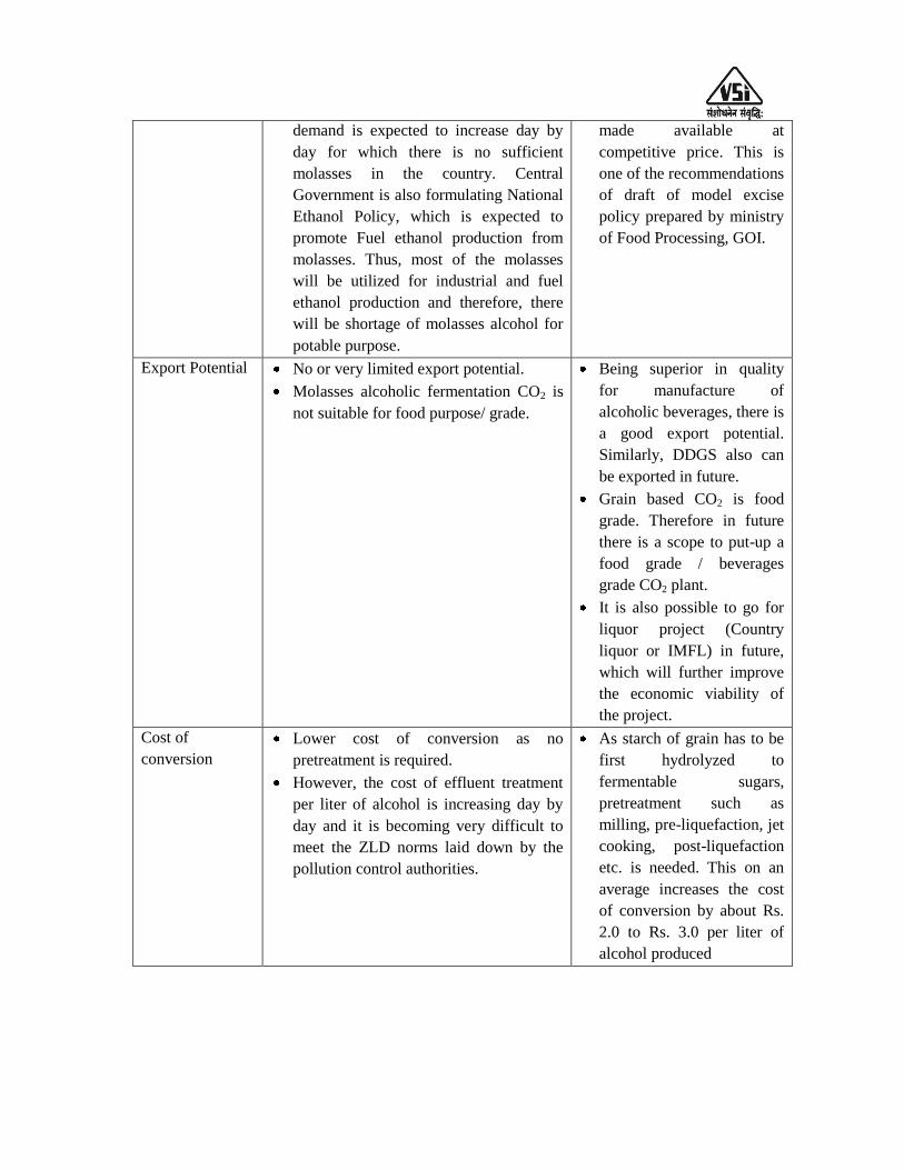
Export Potential
No or very limited export potential.
Molasses alcoholic fermentation CO2 is
not suitable for food purpose/ grade.
Being superior in quality
for manufacture of
alcoholic beverages, there is
a good export potential.
Similarly, DDGS also can
be exported in future.
Grain based CO2 is food
grade. Therefore in future
there is a scope to put-up a
food grade / beverages
grade CO2 plant.
It is also possible to go for
liquor project (Country
liquor or IMFL) in future,
which will further improve
the economic viability of
the project.
Cost of
conversion
Lower cost of conversion as no
pretreatment is required.
However, the cost of effluent treatment
per liter of alcohol is increasing day by
day and it is becoming very difficult to
meet the ZLD norms laid down by the
pollution control authorities.
As starch of grain has to be
first hydrolyzed to
fermentable sugars,
pretreatment such as
milling, pre-liquefaction, jet
cooking, post-liquefaction
etc. is needed. This on an
average increases the cost
of conversion by about Rs.
2.0 to Rs. 3.0 per liter of
alcohol produced
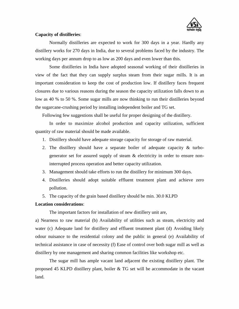
Capacity of distilleries:
Normally distilleries are expected to work for 300 days in a year. Hardly any
distillery works for 270 days in India, due to several problems faced by the industry. The
working days per annum drop to as low as 200 days and even lower than this.
Some distilleries in India have adopted seasonal working of their distilleries in
view of the fact that they can supply surplus steam from their sugar mills. It is an
important consideration to keep the cost of production low. If distillery faces frequent
closures due to various reasons during the season the capacity utilization falls down to as
low as 40 % to 50 %. Some sugar mills are now thinking to run their distilleries beyond
the sugarcane-crushing period by installing independent boiler and TG set.
Following few suggestions shall be useful for proper designing of the distillery.
In order to maximize alcohol production and capacity utilization, sufficient
quantity of raw material should be made available.
1. Distillery should have adequate storage capacity for storage of raw material.
2. The distillery should have a separate boiler of adequate capacity & turbo-
generator set for assured supply of steam & electricity in order to ensure non-
interrupted process operation and better capacity utilization.
3. Management should take efforts to run the distillery for minimum 300 days.
4. Distilleries should adopt suitable effluent treatment plant and achieve zero
pollution.
5. The capacity of the grain based distillery should be min. 30.0 KLPD
Location considerations:
The important factors for installation of new distillery unit are,
a) Nearness to raw material (b) Availability of utilities such as steam, electricity and
water (c) Adequate land for distillery and effluent treatment plant (d) Avoiding likely
odour nuisance to the residential colony and the public in general (e) Availability of
technical assistance in case of necessity (f) Ease of control over both sugar mill as well as
distillery by one management and sharing common facilities like workshop etc.
The sugar mill has ample vacant land adjacent the existing distillery plant. The
proposed 45 KLPD distillery plant, boiler & TG set will be accommodate in the vacant
land.

Raw material availability and storage:-
For the proposed 45 KLPD grain based distillery, it will be necessary to have
scientifically designed storage facility. During the period when grain prices are running
low it is advisable to purchase sufficient quantity and store it for use in other seasons.
Usually, 5.0 to 10.0 % losses take place during storage of grains and therefore, necessary
care should be taken to prevent losses during storage. 30 days storage silos (2 numbers)
to store grains are considered in the cost of the project. If it is required, additional storage
capacity (godowns) can be taken on rental basis in nearby area. These godowns will be
properly modified to minimize losses during storage.
World‟s grains production countries is given in the table 2.4. Similarly, world‟s
top ten countries for corn, rice, wheat, sorghum and sugarcane production is given in the
table 2.5.
Corn from other neighboring states and other grains (such as rice) also can be
made available for the proposed grain based distillery unit. Thus, the requirement of
33,000 MT of grains/annum (such as corn, rice etc. containing min. 62% starch) for the
proposed distillery can be easily made available. The following table nos. 2.3 & 2.4
shows world‟s top most grain production countries.
Table 2.3: World’s grains production countries
Cereals First Second Third Fourth Fifth
Barley Russia Germany France Canada Turkey
Buckwheat Russia China Ukraine France Poland
Maize (corn) United States China Brazil Argentina Ukraine
Millet India Niger China Mali Burkina Faso
Oat Russia Canada Finland Poland Australia
Rice, paddy China India Indonesia Bangladesh Vietnam
Rye Germany Russia Poland Belarus Ukraine
Sorghum United States Mexico Nigeria India Ethiopia
Triticale Poland Germany France Belgium Russia
Wheat China India United States Russia France

Table 2.4: World’s top 10 countries for production of
corn, rice, wheat & sugarcane:
1) Corn production:-
Rank Country Production in 1000 MT
1 United states 3,84,778
2 China 2,19,554
3 Brazil 86,500
4 European Union 60,309
5 Argentina 36,500
6 Ukraine 28,000
7 Mexico 26,000
8 India 24,500
9 Russia 15,500
10 Canada 13,200
Source: https://apps.fas.usda.gov
2) Rice production:-
Rank Country Production in 1000 MT
1 China 1,44,560
2 India 1,04,800
3 Indonesia 35,560
4 Bangladesh 34,500
5 Vietnam 28,234
6 Thailand 18,750
7 Burma 12,600
8 Philippines 11,915
9 Brazil 8,465
10 Japan 7,842
Source: https://apps.fas.usda.gov
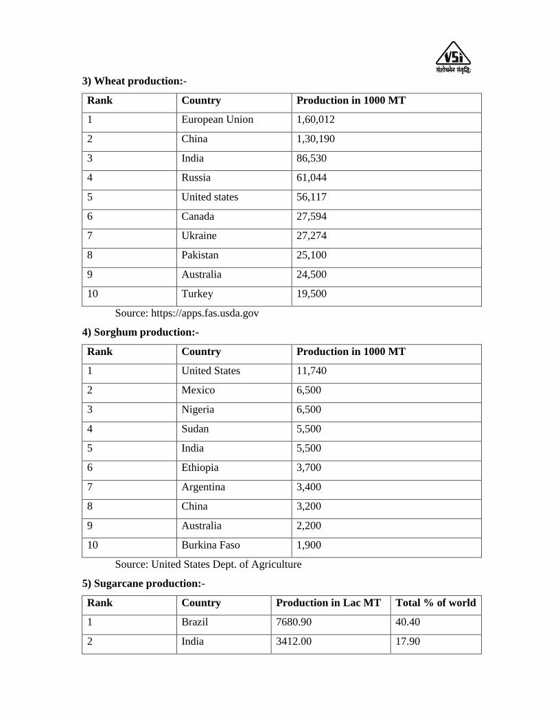
3) Wheat production:-
Rank Country Production in 1000 MT
1 European Union 1,60,012
2 China 1,30,190
3 India 86,530
4 Russia 61,044
5 United states 56,117
6 Canada 27,594
7 Ukraine 27,274
8 Pakistan 25,100
9 Australia 24,500
10 Turkey 19,500
Source: https://apps.fas.usda.gov
4) Sorghum production:-
Rank Country Production in 1000 MT
1 United States 11,740
2 Mexico 6,500
3 Nigeria 6,500
4 Sudan 5,500
5 India 5,500
6 Ethiopia 3,700
7 Argentina 3,400
8 China 3,200
9 Australia 2,200
10 Burkina Faso 1,900
Source: United States Dept. of Agriculture
5) Sugarcane production:-
Rank Country Production in Lac MT Total % of world
1 Brazil 7680.90 40.40
2 India 3412.00 17.90
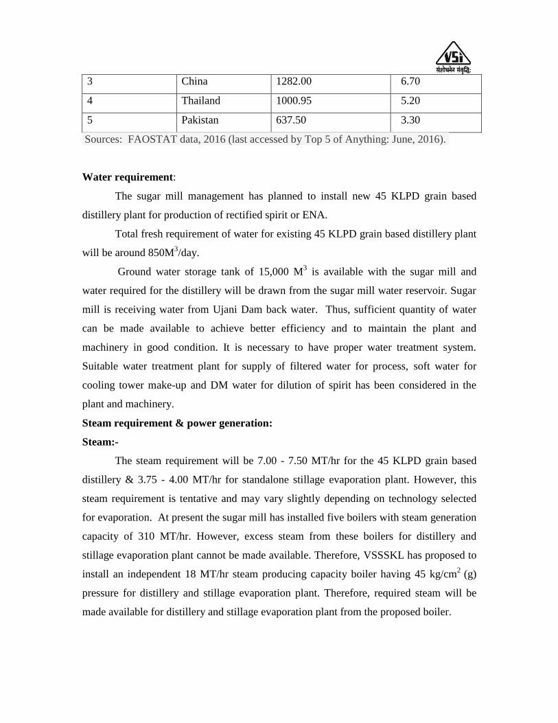
3 China 1282.00 6.70
4 Thailand 1000.95 5.20
5 Pakistan 637.50 3.30
Sources: FAOSTAT data, 2016 (last accessed by Top 5 of Anything: June, 2016).
Water requirement:
The sugar mill management has planned to install new 45 KLPD grain based
distillery plant for production of rectified spirit or ENA.
Total fresh requirement of water for existing 45 KLPD grain based distillery plant
will be around 850M3/day.
Ground water storage tank of 15,000 M3 is available with the sugar mill and
water required for the distillery will be drawn from the sugar mill water reservoir. Sugar
mill is receiving water from Ujani Dam back water. Thus, sufficient quantity of water
can be made available to achieve better efficiency and to maintain the plant and
machinery in good condition. It is necessary to have proper water treatment system.
Suitable water treatment plant for supply of filtered water for process, soft water for
cooling tower make-up and DM water for dilution of spirit has been considered in the
plant and machinery.
Steam requirement & power generation:
Steam:-
The steam requirement will be 7.00 - 7.50 MT/hr for the 45 KLPD grain based
distillery & 3.75 - 4.00 MT/hr for standalone stillage evaporation plant. However, this
steam requirement is tentative and may vary slightly depending on technology selected
for evaporation. At present the sugar mill has installed five boilers with steam generation
capacity of 310 MT/hr. However, excess steam from these boilers for distillery and
stillage evaporation plant cannot be made available. Therefore, VSSSKL has proposed to
install an independent 18 MT/hr steam producing capacity boiler having 45 kg/cm2
(g)
pressure for distillery and stillage evaporation plant. Therefore, required steam will be
made available for distillery and stillage evaporation plant from the proposed boiler.

Power: -
Existing power generation capacity of VSSSKL is 49 MW during crushing
season. VSSSKL is going to install 18 MT/hr capacity new boiler and 1.50 MW capacity
new turbine separately for distillery and ETP system. The estimated requirement of
power for existing & proposed distillery as well as ETP will be 1400 KWH. The required
electricity for 45KLPD distillery & ETP will be generated and supplied from the
independent distillery boiler and TG set.
Power for idle days will be supplied through the DG set of the sugar mill or
purchased from State Electricity Board at the rate of Rs. 5.20/unit and Rs. 9.20/unit
respectively.
It will be also necessary to work out the exact steam and power balance during the
tendering process for the 45 KLPD distillery unit & new multiple effect evaporation plant
& new boiler with TG set.
The services of workers and the engineering staff of the sugar mill could be
readily made available in case of necessity. The nearness of the distillery to sugar mill is
also of advantageous from the point of security.

CHAPTER - IV: MANUFACTURING PROCESS FOR
ALCOHOL
The proposed 45 KLPD distillery will utilize corn or rice as the basic raw
material to produce either potable quality Rectified Spirit (R.S.) or potable quality super
fine Extra Neutral Alcohol (ENA). Along with the main product the distillery will also
produce animal feed called as Distillers' Dried Grain with Soluble (DDGS) or Distillers'
Wet Grain with Soluble (DWGS), which will fetch additional income. The whole
integrated approach and production of DWGS or DDGS will result in zero discharge or
there will be no process effluent coming out of the distillery as in the case of
conventional distilleries based on molasses. The process will be based on Dry Milling
Technology. The overall set-up of grain based distillery with utilities and effluent
treatment plants is shown in the flow-diagram (Figure 4.6) on the next page.
Basic of alcoholic fermentation:
During the fermentation, yeast strains of the species Saccharomyces Cerevisiae, a
living microorganism belonging to class fungi converts sugar (Glucose, Fructose,
Sucrose, Maltose or Maltotrioes) present in the molasses or sugar cane juice to alcohol.
However, Saccharomyces Cerevisiae cannot use starch as such. To produce alcohol from
starch containing raw materials such as grains or cassava etc. by fermentation, the starch
has to first hydrolyze to glucose. Industrially, this conversion is accomplished by cooking
of starch slurry and use of enzymes to breakdown the polymers of glucose (Amylose and
Amylopectin), Transformation of starch to glucose consists of Gelatinization (Cooking),
Liquefaction and Saccharification. Chemically this transformation to alcohol can be
approximated by the equation:
The overall transformation takes place into two steps:-
1) n(C6H10O5) + n(H2O) Amylase / Gluco-amylase n(C6H12O6)
n (162) + n (18) n (180)
Starch + Water
2) C6H12O6 Saccharomyces cerevisiae 2C2H5OH + 2CO2
180 gm 92 gm 88 gm
As per above reaction 162 gm of starch produces 180 gm of glucose. Therefore, 1
MT of starch gives 1111.11 gm of glucose.
180 gm. of glucose on reaction gives 92 gm. of alcohol. Therefore, 1 MT of sugar
gives 511.1 kgs of alcohol. The specific gravity of alcohol is 0.7934, therefore, 511.1 kg.
of alcohol is equivalent to 511.1/0.7934 = 644.19 litres of Alcohol. During fermentation,
other by-products like glycerin, succinic acids etc also are formed from sugars.
Therefore, actually 94.5% total fermentable sugars are available for alcohol conversion.
Thus, one MT of sugar will give only 644 x 0.945 = 608.6 litres of alcohol, under ideal
conditions theoretically. Similarly, one MT of pure starch should give 715.0 liters of
alcohol under ideal conditions, theoretically (at 100 % efficiency and 100 % ethanol).
Corn or sorghum contains about 62.0 % starch on dry weight basis. Therefore, one MT of
corn or sorghum can yield about 410 liters of Rectified Spirit.
For bringing out above biochemical reaction, we require proper and careful
handling of yeast, control of optimum parameters like pH and temperature and substrate
concentration and enzyme dose, which results into effective conversion of starch to
sugars and then to alcohol.
For propagation, yeast is developed in the laboratory from the pure yeast culture
slant. In first step yeast is propagated in a test tube. Then it is transferred to a 500ml
conical flask and propagated for 12 hrs. This is further transferred to 5 litres flask
containing the sterilized medium. The pH of the medium is adjusted in the range of 4.5
and nutrients such as ammonium sulphate or urea, di-ammonium phosphate etc. are
added. Each stage of development of yeast from test tube to 500ml and 500ml to 5 litres
requires 24 hours.
On the plant, there are again 3 stages of propagation namely 100 litres, 500 litres
and 5000 litres of culture vessels. All these vessels are designed so as to facilitate boiling
medium in order to sterilize it and also cool to bring it to the proper temperature of 320C.
Further stages of yeast propagation are done in tanks. i.e. Pre-fermenters, which requires
about 8 hours in order to build up necessary concentration of yeast cell mass. Finally pre-
fermenter is transferred in the fermenter. Simultaneously grain slurry is transferred to
fermenter.

Now a day, readymade active dry yeast is used directly in the pre-fermenters.
Good quality of active dry yeast is available for use in distillery. The yeast is
manufactured under strict controlled conditions. This yeast is useful to obtain a good
yield of alcohol by fermentation.
Grain based distillery plant process details
Raw material
Mostly Broken Rice, Maize, Millet and Sorghum or mixed grains are being used
as raw material in the distillery units. Following table no. 4.1 & 4.2 are indicating the
starch percentage & alcohol yield from various grains.
Table 4.1: Grain starch percentage and alcohol yields
Sr.
No.
Grain Fermentable carbohydrate
(Starch %)
Alcohol yield
(Lits. of alcohol/MT)
1 Rice 62-67 380-418
2 Sorghum 62-65 380-410
3 Wheat 62-65 380-410
4 Maize 62-65 380-410
5 Malt 58-59 389-395
Table 4.2: Composition of various grains
Grain Moisture (% w/w)
Starch (% w/w)
Proteins (% w/w)
Fats (% w/w)
Crude
Fiber (% w/w)
Ash (% w/w)
Other
Solids (% w/w)
Rice 8-10 65-70 7-8 1-1.2 0.8-1 0.8-1 8.8-9
Wheat 8-12 59-63 11-13 1-2 2-3 1.5-2.5 7-10
Corn 8-12 60-64 9-12 3.5-6 1.5-2 1-2.5 7-10
Sorghum 9-10 65-70 7-8 3-3.5 2.3-2.5 1.5-1.6 1.5-1.7
Millet 8-10 65-70 10-11 4-4.2 0.8-1 3-3.3 1.8-2
Barley 7.5-8 60-63 7-9 2.5-3.5 9-10 1.5-2.5 6-8
Starch hydrolysis: Starch can be hydrolyzed to fermentable sugar (Glucose) by
enzymatic hydrolysis. Following two enzymes are commonly used for starch
hydrolysis in grain based distillery.
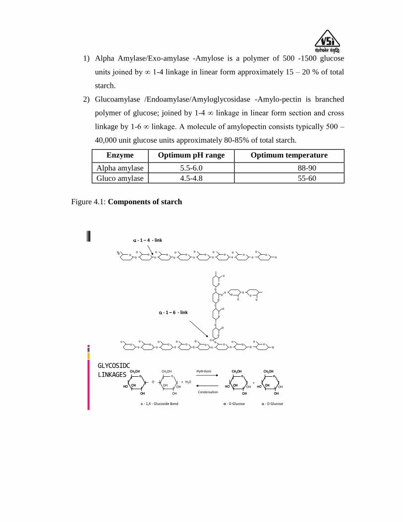
1) Alpha Amylase/Exo-amylase -Amylose is a polymer of 500 -1500 glucose
units joined by ∞ 1-4 linkage in linear form approximately 15 – 20 % of total
starch.
2) Glucoamylase /Endoamylase/Amyloglycosidase -Amylo-pectin is branched
polymer of glucose; joined by 1-4 ∞ linkage in linear form section and cross
linkage by 1-6 ∞ linkage. A molecule of amylopectin consists typically 500 –
40,000 unit glucose units approximately 80-85% of total starch.
Enzyme Optimum pH range Optimum temperature
Alpha amylase 5.5-6.0 88-90
Gluco amylase 4.5-4.8 55-60
Figure 4.1: Components of starch
OH
OH
CH2OHo
HO OH
OH
CH2OHo
HO OH OH
OH
CH2OHo
HO OH
OH
CH2OHo
HO OHO
OH
CH2OHo
HO OH
OH
CH2OHo
HO OH OH
OH
CH2OHo
OH+ H2O
Hydrolysis
Condensation
- D Glucose - D Glucose
+
- 1,4 - Glucoside Bond
oo
o
oo
o
oo
o
oo
o
oo
o
oo
o
oo
o
o o
o
o
oo
o
o
oo
o
oo o
oo o
o
o
o
o
ooo o o o o o o o
oo
oo
oo
oo
oo
oo
oo
o
- 1 – 4 - link
- 1 – 6 - link
GLYCOSIDC LINKAGES

Process Description:-
The incoming grains (corn or sorghum or rice) are inspected upon receipt.
Inspection is carried out to determine the starch content, bushel weight, moisture content,
mold infestation and general appearance. The accepted quality corn grain is unloaded into
silos for storage before milling. The stored grain is weighed to determine the incoming
quantity.
Silos for grain storage:-
Grain Handling & Milling:-
System involved in Grain handling system:
1. Grain Unloading: Involves receiving hopper with magnetic grill and bucket
elevator.
2. Grain Storage: Storage silos with feeding arrangement and sweep auger and
chain conveyor for discharge.
3. Grain cleaning: Involves pre-cleaner (vibratory screen) separating oversize and
undersize impurities, Destoner for removing stones and magnetic drum separator
for removing iron particles.
4. Grain Milling: Involves rotary feeder for controlled feed, hammer mill to achieve
desired particle size and capacity. Hammer mill discharge arrangement with
screw conveyor, rotary screen for coarse separation.
5. Flour handling: Involves mechanical or pneumatic conveying, screw conveyor,
bucket elevator, rotary valves with roots blowers.
6. Flour Storage: Flour storage silo is provided with bin activator for a smooth
discharge. Silo is provided with level switches high and low and load cells for
weighing/automation.
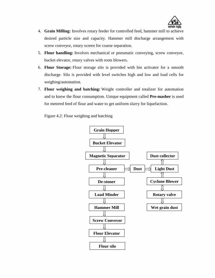
7. Flour weighing and batching: Weight controller and totalizer for automation
and to know the flour consumption. Unique equipment called Pre-masher is used
for metered feed of flour and water to get uniform slurry for liquefaction.
Figure 4.2: Flour weighing and batching
Grain Hopper
Bucket Elevator
Magnetic Separator
Pre-cleaner
De-stoner
Load Minder
Hammer Mill
Screw Conveyor
Flour Elevator
Flour silo
Dust Light Dust
Dust collector
Cyclone Blower
Rotary valve
Wet grain dust
Grains are stored in the silos from there it is conveyed through screw conveyor to
bucket elevator. Bucket elevator lifts the grains to approximately 18m height and then
passes the grains through vibrating screen, de-stoner and magnetic separator to remove
dust and stones, the flow through this equipment are under gravity.
The cleaned grains are then again conveyed by bucket elevator to an intermediate
hopper, which are provided with rotary air lock system for controlled flow in hammer
mill. In hammer mill the particle size is reduced (Size 400-700µ) as per required for the
process. The size distribution test or "sieve analysis" of the flour is done regularly in
order to ascertain the mill setting and particle size distribution. From hammer mill the
flour is pneumatically conveyed to flour bin (Intermediate storage for flour). From flour
bin the flour is carried to pre-masher for slurry preparation.
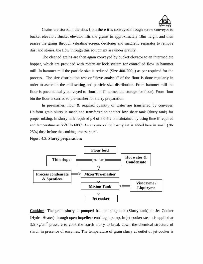
In pre-masher, flour & required quantity of water are transferred by conveyer.
Uniform grain slurry is made and transferred to another low shear tank (slurry tank) for
proper mixing. In slurry tank required pH of 6.0-6.2 is maintained by using lime if required
and temperature as 550C to 600C. An enzyme called α-amylase is added here in small (20-
25%) dose before the cooking process starts.
Figure 4.3: Slurry preparation:
Cooking: The grain slurry is pumped from mixing tank (Slurry tank) to Jet Cooker
(Hydro Heater) through open impeller centrifugal pump. In jet cooker steam is applied at
3.5 kg/cm2 pressure to cook the starch slurry to break down the chemical structure of
starch in presence of enzymes. The temperature of grain slurry at outlet of jet cooker is
Flour feed
Mixer/Pre-masher
Mixing Tank
Jet cooker
Hot water &
Condensate
Viscozyme /
Liquizyme
Thin slope
Process condensate
& Spentlees

maintained between 115 to 1200C, after cooking the grain slurry is passed through the
retention vessel to provide desired retention time at a given flow rate to convert starch
into dextrin. In this step slurry pressure & viscosity reduces. The slurry which is hot is
transferred into the flash tank to reduce the temperature of the slurry to 90- 950C before
sending to final liquefaction tank. Flash tank is attached to flash condensers where
vapours are condensed and condensate is sent to slurry tank.
Figure 4.4: Cooking
Table 4.3: Characteristics of starch in cereal grain
Cereal Grain Gelatinization
Temp.0C
Shape Granule size
(µm)
Barley 51-60 Elliptical
Spherical
20-25
2-6
Wheat 58-64 Lenticular
Round
25-35
2-10
Corn 62-72 Round/Polyhedral 15
Rice 68-78 Polygonal 3-8
Sorghum 68-78 Round 15
Oats 53-59 Polyhedral 3-10
Rye 57-78 Round/ Lenticular 28
Jet cooker
Retention loop
Flash tank
Steam
3.5Kg/cm2
Jet cooker feed
Liquefaction
Vent vapour
Condenser
Steam condensate
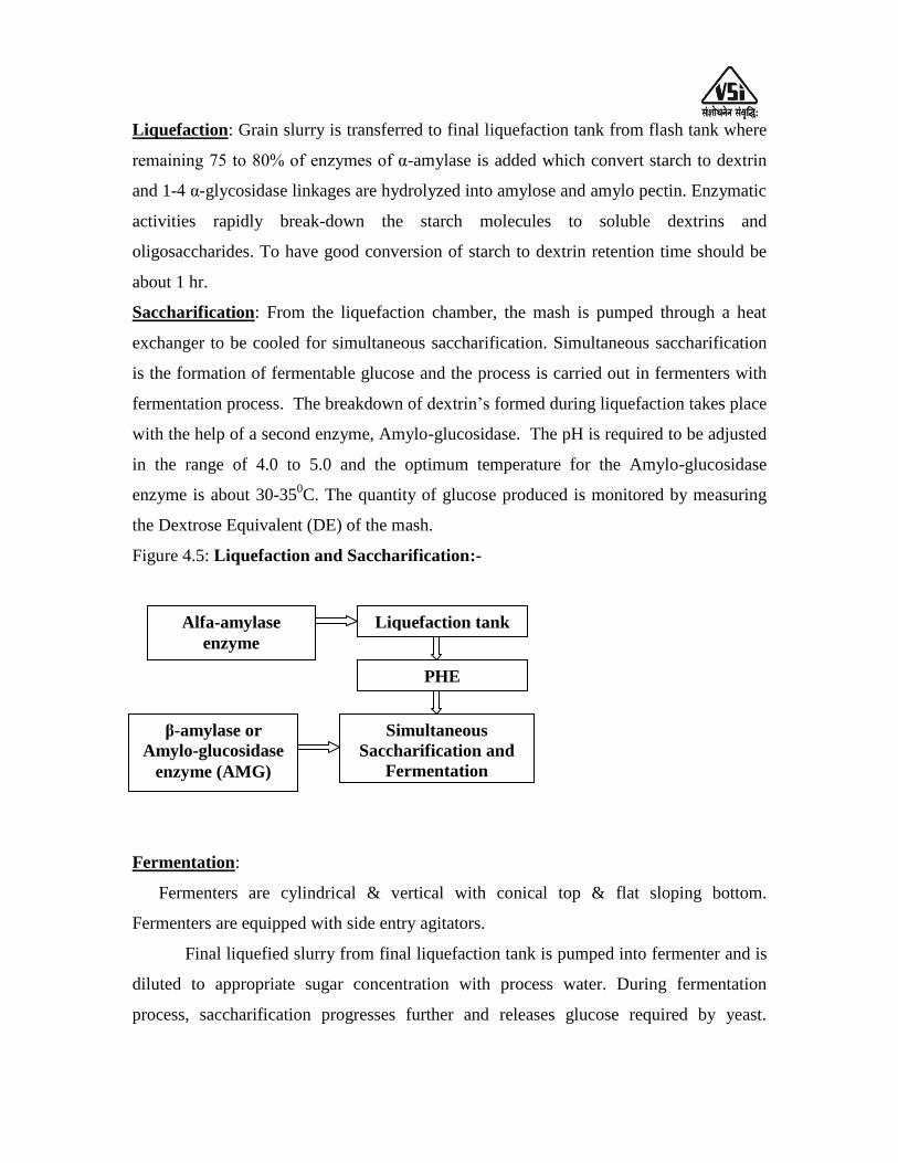
Liquefaction: Grain slurry is transferred to final liquefaction tank from flash tank where
remaining 75 to 80% of enzymes of α-amylase is added which convert starch to dextrin
and 1-4 α-glycosidase linkages are hydrolyzed into amylose and amylo pectin. Enzymatic
activities rapidly break-down the starch molecules to soluble dextrins and
oligosaccharides. To have good conversion of starch to dextrin retention time should be
about 1 hr.
Saccharification: From the liquefaction chamber, the mash is pumped through a heat
exchanger to be cooled for simultaneous saccharification. Simultaneous saccharification
is the formation of fermentable glucose and the process is carried out in fermenters with
fermentation process. The breakdown of dextrin‟s formed during liquefaction takes place
with the help of a second enzyme, Amylo-glucosidase. The pH is required to be adjusted
in the range of 4.0 to 5.0 and the optimum temperature for the Amylo-glucosidase
enzyme is about 30-350C. The quantity of glucose produced is monitored by measuring
the Dextrose Equivalent (DE) of the mash.
Figure 4.5: Liquefaction and Saccharification:-
Fermentation:
Fermenters are cylindrical & vertical with conical top & flat sloping bottom.
Fermenters are equipped with side entry agitators.
Final liquefied slurry from final liquefaction tank is pumped into fermenter and is
diluted to appropriate sugar concentration with process water. During fermentation
process, saccharification progresses further and releases glucose required by yeast.
Liquefaction tank
PHE
Simultaneous
Saccharification and
Fermentation
Alfa-amylase
enzyme
β-amylase or
Amylo-glucosidase
enzyme (AMG)
Fermentation is initiated by inoculating with required quantity of yeast. The assimilable
nitrogen is added in the medium in the form of urea and di-ammonium phosphate.
Temperature in the fermenter is maintained at 32 C with the help of external wide
gap plate heat exchanger (PHE). The fermented mash is re-circulated continuously
through the PHE. Recirculation also helps in proper mixing of fermented mash. The rate
of fermentation reaction gradually increases and after about 55 to 65 hours fermentation
completes. At the end of fermentation, the alcohol concentration in the mash is 10.0 to
12.0 % (v/v). This section will have six fermenters of capacity given 70 hours retention
time. After completion of fermentation the mash is transferred to mash holding tank.
The CO2 which is liberated during fermentation is scrubbed in water, in CO2
scrubber. This CO2 contains alcohol, which is recovered by collecting CO2 scrubber
water into mash holding tank. If required, CO2 can be collected, washed, purified and
compressed in cylinders to be sold in consumption for beverages production. However, in
the present report this aspect is not considered.
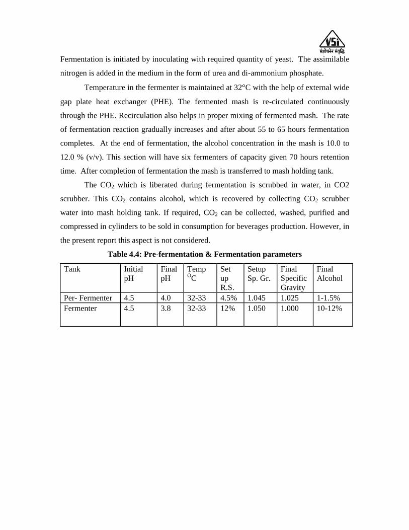
Table 4.4: Pre-fermentation & Fermentation parameters
Tank Initial
pH
Final
pH
Temp OC
Set
up
R.S.
Setup
Sp. Gr.
Final
Specific
Gravity
Final
Alcohol
Per- Fermenter 4.5 4.0 32-33 4.5% 1.045 1.025 1-1.5%
Fermenter 4.5 3.8 32-33 12% 1.050 1.000 10-12%

Figure 4.6: GRAIN TO ETHANOL PROCESS FLOW DIAGRAM
Decantation
Grain Storage
Boiler
Grain Handling & Dry Milling
Thin stillage TG set
Liquefaction, cooking
& post- liquefaction
Evaporation
Cooling
Tower
Saccharification &
Fermentation
Mingler
WTP & Treatment
DWGS
Distillation- Product
R.S. or ENA
Dryer
DDGS
Condensate
Secondary ETP
Power to all electrical
equipments
R.S. to storage
Impure spirit to
storage
ENA to
storage
Wet
cake
Syrup
Treated water

CHAPTER-V: MULTIPRESSURE DISTILLATION TECHNOLOGY
After fermentation the next stage in the manufacture of alcohol is to separate
alcohol from fermented wash and to concentrate it to 95% (v/v) alcohol called as
Rectified spirit. For this purpose, method of distillation is employed.
It‟s a physical process various compounds of a mixture get separated by virtue of
their differences in boiling points.
The distillation columns consist of number of bubble cap /Rh grid plates where
wash is boiled and alcoholic vapours are separated and concentrated on each plate stage
by stage.
MULTIPRESSURE DISTILLATION:
Vacuum distillation is defined as that in which the operating pressure in the system is
either less than atmospheric pressure or more than atmospheric pressure. Vacuum is nothing
but sub-atmospheric pressure (negative gauge pressure).
Fermented wash to rectified spirit & ENA: Multi-pressure distillation system for
production of Rectified spirit & ENA consists of distillation columns namely-
For –Rectified Spirit mode
1. Degasifying cum analyzer column
2. Rectification column
3. Fusel Oil Concentration column
4. Extractive Distillation column
For –ENA mode
1. Degasifying cum analyzer column
2. Pre-rectifier column
3. Extractive Distillation column
4. Rectification column
5. Refining /Simmering column
6. Fusel Oil Concentration column
7. Head Concentration column
Advantages of MPR Distillation:
1) Maximum Heat Integration is possible.
2) Few columns operate under vacuum, few under pressure and few under
atmospheric pressure.
3) Resolution of impurities is better.
4) Analyzer column operates under vacuum. Therefore Scaling is minimized in
distillation.
5) Formation of by-products such as acetal is minimized - improvement in
quality of alcohol.
6) Pre-rectification column ensure removal of sulfur compounds /mercaptans,
reduces load of lower boiling volatile compounds
7) Low steam consumption with reboiler (2.2 Kg/lit. of Rectified Spirit)
8) Stillage generation is less.
The distillation system is designed for the production of potable alcohol. The
distillation system comprises seven columns namely Analyzer/Degasifying column, Pre-
rectifier column, Extraction column, Second Rectifier column & Refining column. The
Fusel Oil column, Head Concentration column are used for concentrating & removal of
Fusel Oil & impurities. After separation of impurities the recovered alcohol is recycled
back to the pre rectifier column system.
Process –
The fermentation mash containing alcohol, non-fermentable solids and water is
supplied to Distillation to separate the alcohol and other impurities, as a continuous flow.
The Distillation system is designed for premium quality Extra Neutral Alcohol.
The system details are as below:
The system consists of 7 main columns, namely, Degassifier, Stripper column,
Pre-rectifier column, Extraction column, Rectification column, Refining column, Fusel
Oil column.
Wash is fed to Degassifier/ Stripper column. Top vapours of Degassifier are fed
to Condensers. Alcohol is stripped off water in stripper column. The top vapours from
stripper column are fed to pre-rectifier column as feed and as heat source too. The
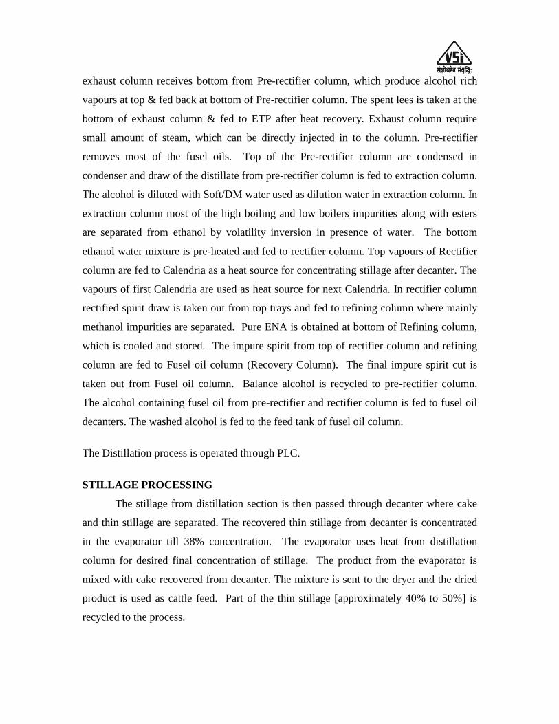
exhaust column receives bottom from Pre-rectifier column, which produce alcohol rich
vapours at top & fed back at bottom of Pre-rectifier column. The spent lees is taken at the
bottom of exhaust column & fed to ETP after heat recovery. Exhaust column require
small amount of steam, which can be directly injected in to the column. Pre-rectifier
removes most of the fusel oils. Top of the Pre-rectifier column are condensed in
condenser and draw of the distillate from pre-rectifier column is fed to extraction column.
The alcohol is diluted with Soft/DM water used as dilution water in extraction column. In
extraction column most of the high boiling and low boilers impurities along with esters
are separated from ethanol by volatility inversion in presence of water. The bottom
ethanol water mixture is pre-heated and fed to rectifier column. Top vapours of Rectifier
column are fed to Calendria as a heat source for concentrating stillage after decanter. The
vapours of first Calendria are used as heat source for next Calendria. In rectifier column
rectified spirit draw is taken out from top trays and fed to refining column where mainly
methanol impurities are separated. Pure ENA is obtained at bottom of Refining column,
which is cooled and stored. The impure spirit from top of rectifier column and refining
column are fed to Fusel oil column (Recovery Column). The final impure spirit cut is
taken out from Fusel oil column. Balance alcohol is recycled to pre-rectifier column.
The alcohol containing fusel oil from pre-rectifier and rectifier column is fed to fusel oil
decanters. The washed alcohol is fed to the feed tank of fusel oil column.
The Distillation process is operated through PLC.
STILLAGE PROCESSING
The stillage from distillation section is then passed through decanter where cake
and thin stillage are separated. The recovered thin stillage from decanter is concentrated
in the evaporator till 38% concentration. The evaporator uses heat from distillation
column for desired final concentration of stillage. The product from the evaporator is
mixed with cake recovered from decanter. The mixture is sent to the dryer and the dried
product is used as cattle feed. Part of the thin stillage [approximately 40% to 50%] is
recycled to the process.
CHAPTER –VI: DISTILLERY PLANT AND MACHINERY
SPECIFICATIONS
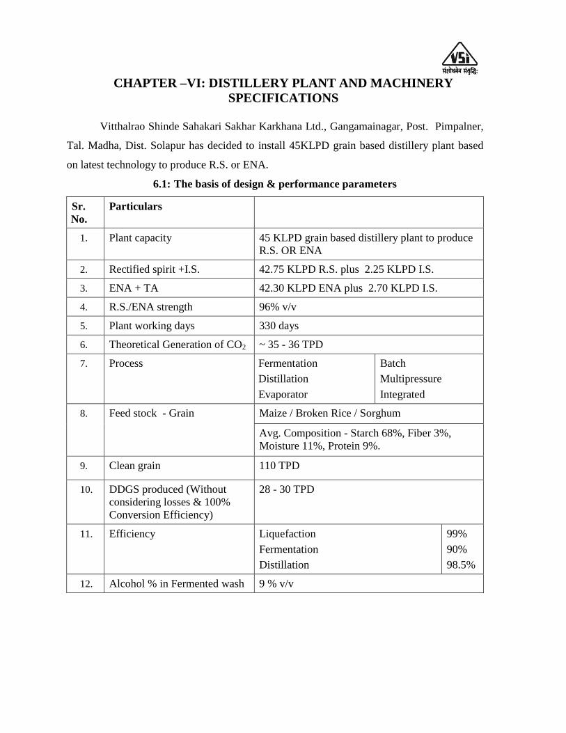
Vitthalrao Shinde Sahakari Sakhar Karkhana Ltd., Gangamainagar, Post. Pimpalner,
Tal. Madha, Dist. Solapur has decided to install 45KLPD grain based distillery plant based
on latest technology to produce R.S. or ENA.
6.1: The basis of design & performance parameters
Sr.
No.
Particulars
1. Plant capacity 45 KLPD grain based distillery plant to produce
R.S. OR ENA
2. Rectified spirit +I.S. 42.75 KLPD R.S. plus 2.25 KLPD I.S.
3. ENA + TA 42.30 KLPD ENA plus 2.70 KLPD I.S.
4. R.S./ENA strength 96% v/v
5. Plant working days 330 days
6. Theoretical Generation of CO2 ~ 35 - 36 TPD
7. Process Fermentation
Distillation
Evaporator
Batch
Multipressure
Integrated
8. Feed stock - Grain
Maize / Broken Rice / Sorghum
Avg. Composition - Starch 68%, Fiber 3%,
Moisture 11%, Protein 9%.
9. Clean grain 110 TPD
10. DDGS produced (Without
considering losses & 100%
Conversion Efficiency)
28 - 30 TPD
11. Efficiency Liquefaction
Fermentation
Distillation
99%
90%
98.5%
12. Alcohol % in Fermented wash 9 % v/v
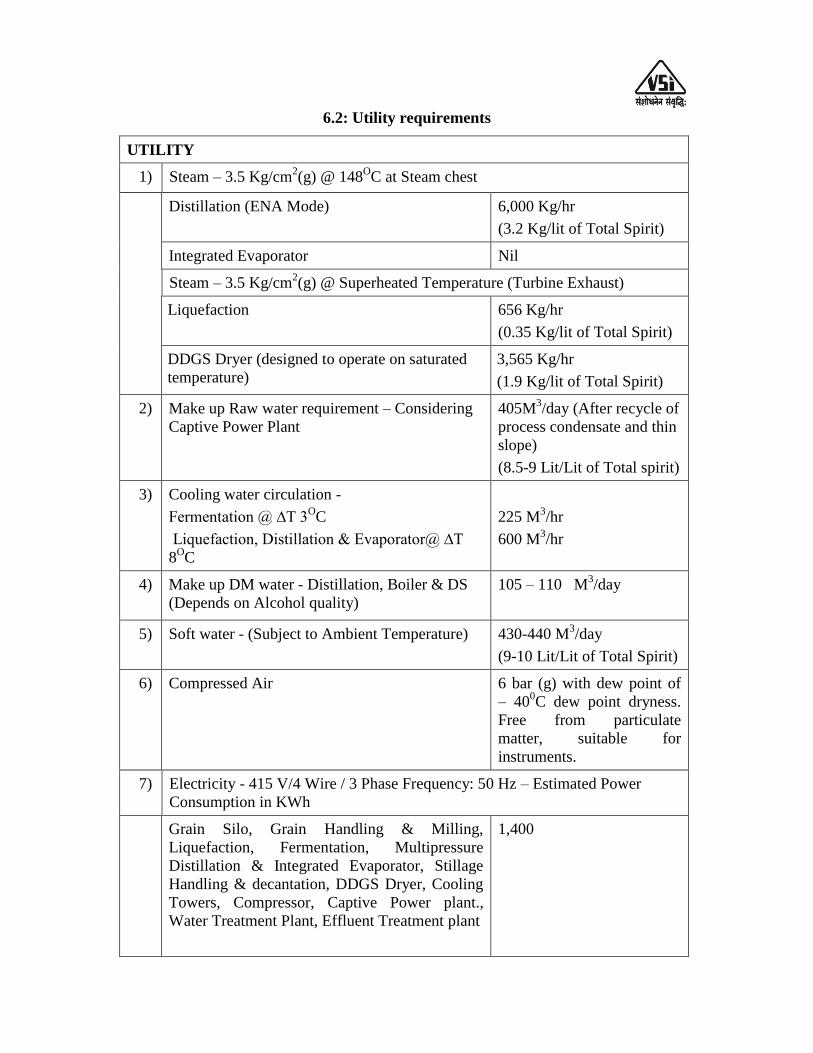
6.2: Utility requirements
UTILITY
1) Steam – 3.5 Kg/cm2(g) @ 148
OC at Steam chest
Distillation (ENA Mode) 6,000 Kg/hr
(3.2 Kg/lit of Total Spirit)
Integrated Evaporator Nil
Steam – 3.5 Kg/cm2(g) @ Superheated Temperature (Turbine Exhaust)
Liquefaction 656 Kg/hr
(0.35 Kg/lit of Total Spirit)
DDGS Dryer (designed to operate on saturated
temperature)
3,565 Kg/hr
(1.9 Kg/lit of Total Spirit)
2) Make up Raw water requirement – Considering
Captive Power Plant
405M3/day (After recycle of
process condensate and thin
slope)
(8.5-9 Lit/Lit of Total spirit)
3) Cooling water circulation -
Fermentation @ ∆T 3OC
Liquefaction, Distillation & Evaporator@ ∆T
8OC
225 M3/hr
600 M3/hr
4) Make up DM water - Distillation, Boiler & DS
(Depends on Alcohol quality)
105 – 110 M3/day
5) Soft water - (Subject to Ambient Temperature) 430-440 M3/day
(9-10 Lit/Lit of Total Spirit)
6) Compressed Air 6 bar (g) with dew point of
– 400C dew point dryness.
Free from particulate
matter, suitable for
instruments.
7) Electricity - 415 V/4 Wire / 3 Phase Frequency: 50 Hz – Estimated Power
Consumption in KWh
Grain Silo, Grain Handling & Milling,
Liquefaction, Fermentation, Multipressure
Distillation & Integrated Evaporator, Stillage
Handling & decantation, DDGS Dryer, Cooling
Towers, Compressor, Captive Power plant.,
Water Treatment Plant, Effluent Treatment plant
1,400
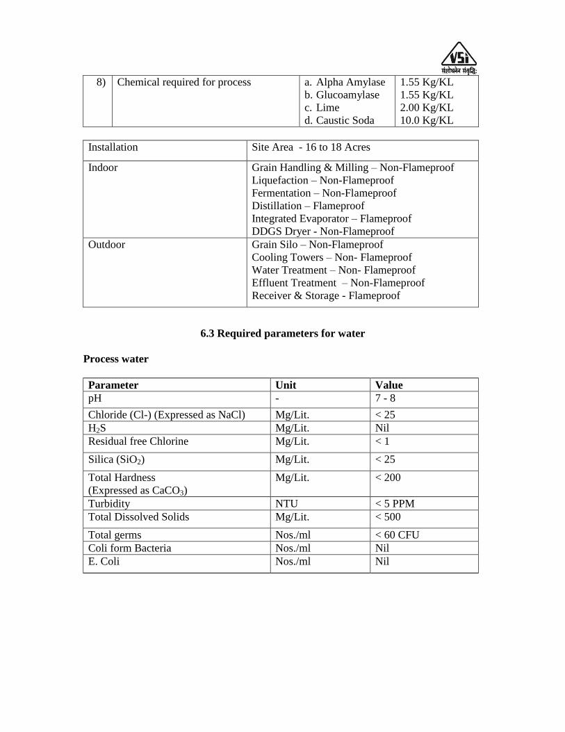
8) Chemical required for process a. Alpha Amylase
b. Glucoamylase
c. Lime
d. Caustic Soda
1.55 Kg/KL
1.55 Kg/KL
2.00 Kg/KL
10.0 Kg/KL
Installation Site Area - 16 to 18 Acres
Indoor Grain Handling & Milling – Non-Flameproof
Liquefaction – Non-Flameproof
Fermentation – Non-Flameproof
Distillation – Flameproof
Integrated Evaporator – Flameproof
DDGS Dryer - Non-Flameproof
Outdoor Grain Silo – Non-Flameproof
Cooling Towers – Non- Flameproof
Water Treatment – Non- Flameproof
Effluent Treatment – Non-Flameproof
Receiver & Storage - Flameproof
6.3 Required parameters for water
Process water
Parameter Unit Value
pH - 7 - 8
Chloride (Cl-) (Expressed as NaCl) Mg/Lit. < 25
H2S Mg/Lit. Nil
Residual free Chlorine Mg/Lit. < 1
Silica (SiO2) Mg/Lit. < 25
Total Hardness
(Expressed as CaCO3)
Mg/Lit. < 200
Turbidity NTU < 5 PPM
Total Dissolved Solids Mg/Lit. < 500
Total germs Nos./ml < 60 CFU
Coli form Bacteria Nos./ml Nil
E. Coli Nos./ml Nil
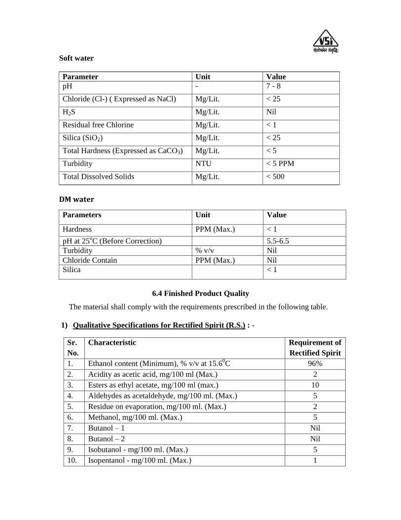
Soft water
Parameter Unit Value
pH - 7 - 8
Chloride (Cl-) ( Expressed as NaCl) Mg/Lit. < 25
H2S Mg/Lit. Nil
Residual free Chlorine Mg/Lit. < 1
Silica (SiO2) Mg/Lit. < 25
Total Hardness (Expressed as CaCO3) Mg/Lit. < 5
Turbidity NTU < 5 PPM
Total Dissolved Solids Mg/Lit. < 500
DM water
Parameters Unit Value
Hardness PPM (Max.) < 1
pH at 25oC (Before Correction) 5.5-6.5
Turbidity % v/v Nil
Chloride Contain PPM (Max.) Nil
Silica < 1
6.4 Finished Product Quality
The material shall comply with the requirements prescribed in the following table.
1) Qualitative Specifications for Rectified Spirit (R.S.) : -
Sr.
No.
Characteristic Requirement of
Rectified Spirit
1. Ethanol content (Minimum), % v/v at 15.60C 96%
2. Acidity as acetic acid, mg/100 ml (Max.) 2
3. Esters as ethyl acetate, mg/100 ml (max.) 10
4. Aldehydes as acetaldehyde, mg/100 ml. (Max.) 5
5. Residue on evaporation, mg/100 ml. (Max.) 2
6. Methanol, mg/100 ml. (Max.) 5
7. Butanol – 1 Nil
8. Butanol – 2 Nil
9. Isobutanol - mg/100 ml. (Max.) 5
10. Isopentanol - mg/100 ml. (Max.) 1
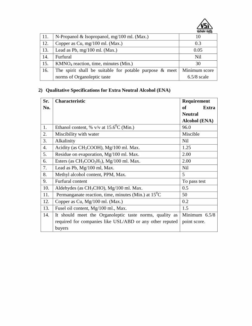
11. N-Propanol & Isopropanol, mg/100 ml. (Max.) 10
12. Copper as Cu, mg/100 ml. (Max.) 0.3
13. Lead as Pb, mg/100 ml. (Max.) 0.05
14. Furfural Nil
15. KMNO4 reaction, time, minutes (Min.) 30
16. The spirit shall be suitable for potable purpose & meet
norms of Organoleptic taste
Minimum score
6.5/8 scale
2) Qualitative Specifications for Extra Neutral Alcohol (ENA)
Sr.
No.
Characteristic Requirement
of Extra
Neutral
Alcohol (ENA)
1. Ethanol content, % v/v at 15.60C (Min.) 96.0
2. Miscibility with water Miscible
3. Alkalinity Nil
4. Acidity (as CH3COOH), Mg/100 ml. Max. 1.25
5. Residue on evaporation, Mg/100 ml. Max. 2.00
6. Esters (as CH3COO2H5), Mg/100 ml. Max. 2.00
7. Lead as Pb, Mg/100 ml, Max. Nil
8. Methyl alcohol content, PPM, Max. 5
9. Furfural content To pass test
10. Aldehydes (as CH3CHO), Mg/100 ml. Max. 0.5
11. Permanganate reaction, time, minutes (Min.) at 150C 50
12. Copper as Cu, Mg/100 ml. (Max.) 0.2
13. Fusel oil content, Mg/100 ml., Max. 1.5
14. It should meet the Organoleptic taste norms, quality as
required for companies like USL/ABD or any other reputed
buyers
Minimum 6.5/8
point score.

6.5: SPECIFICATION OF CIVIL AND STRUCTURALWORK FOR PROPOSED
45 KLPD GRAIN BASED PLANT TO PRODUCE R.S. OR ENA
The following are to be considered:-
Wind and soil test to be considered. Details of soil strata & load data.
All design will be as per ISI specification and drawings are to be approved by
factory /electrical inspectorate /safety inspectorate weights & measurement
inspectorate etc.
The plinth level of distillery building will be at min 0.75 mtr height from
developed ground level and it is to be built by brick masonry. For ground floor
flooring of M10 grade (CC1:3:6) as a base concrete is to be made and it‟s IPS
shall be 50 mm of M15 grade (CC1:2:4). Plinth foundation should carry the load
of 4 M height wall safely.
Staircase – M.S. (Chequred plate with supports/grating of 5 mm thick) staircase of
1M wide, 150 mm risers and 300 mm treads with a landing at every 3M
maximum and rails provided on both sides, thus two staircases are provided up to
top floor of plant. The staircases have to be inside the building.
All floors (except ground) of the distillation building should be with MS grating
of 5 mm thickness and each floor height should be minimum 4 M & Chequred
plate at a condenser floor of 6 mm thickness.
All distillation columns accessed from flooring (grating)
The roof of the structures (fermentation, distillation, receivers) must be covered
totally by pre-coated sheets (Pre-painted galvano loom sheet i.e. PPGL sheets) of
0.5 mm thickness.
Pre-coated sheet should cover roofing with extension on both side minimum as
0.75 M. Similarly pre-coated louvers of 0.75M size & 0.5 mm thickness provided
for every floor.
Receivers‟ tanks for R.S. & ENA in a structure of which roof covered in pre-
coated sheets and side walls of structure should be constructed in brick masonry
up to the 2.5 M height and above burnt brick masonry (BBM) wall standard chain
link fencing up to roof.
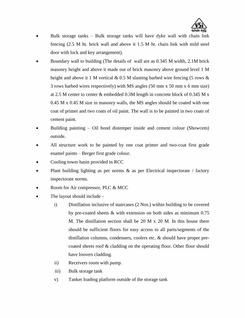
Bulk storage tanks – Bulk storage tanks will have dyke wall with chain link
fencing (2.5 M ht. brick wall and above it 1.5 M ht. chain link with mild steel
door with lock and key arrangement).
Boundary wall to building (The details of wall are as 0.345 M width, 2.1M brick
masonry height and above it made out of brick masonry above ground level 1 M
height and above it 1 M vertical & 0.5 M slanting barbed wire fencing (5 rows &
3 rows barbed wires respectively) with MS angles (50 mm x 50 mm x 6 mm size)
at 2.5 M center to center & embedded 0.3M length in concrete block of 0.345 M x
0.45 M x 0.45 M size in masonry walls, the MS angles should be coated with one
coat of primer and two coats of oil paint. The wall is to be painted in two coats of
cement paint.
Building painting – Oil bond distemper inside and cement colour (Showcem)
outside.
All structure work to be painted by one coat primer and two-coat first grade
enamel paints – Berger first grade colour.
Cooling tower basin provided in RCC
Plant building lighting as per norms & as per Electrical inspectorate / factory
inspectorate norms.
Room for Air compressor, PLC & MCC
The layout should include –
i) Distillation inclusive of staircases (2 Nos.) within building to be covered
by pre-coated sheets & with extension on both sides as minimum 0.75
M. The distillation section shall be 20 M x 20 M. In this house there
should be sufficient floors for easy access to all parts/segments of the
distillation columns, condensers, coolers etc. & should have proper pre-
coated sheets roof & cladding on the operating floor. Other floor should
have louvers cladding.
ii) Receivers room with pump.
iii) Bulk storage tank
v) Tanker loading platform outside of the storage tank

vi) Cooling towers.
vii) Administration building – Existing
viii) Distance between flameproof and non-flame proof area min. 15M.
The layout will take into account the working space & safety requirement of Factory
Inspectorate, Govt. of Maharashtra State.
Structural Work –
Wind and soil test to be considered. Details of soil data and load data are to be
ascertained by purchaser.
Sr.
No.
Section Civil work Structural work
1. Grain Handling &
Milling
RCC column and brick masonry
works around periphery up to
bottom of truss with ventilation.
Staircase in RCC, (i.e. window).
Equipments foundations,
Blowers foundation
Providing roof on top,
trusses,
2. Liquefaction &
Fermentation
Structure building foundation.
Equipment foundation, Pumps,
PHE foundation,
Structural building
enclosed by providing
roof. Operating floor and
other floors with grating
for ease of operation.
Hand rail, Top Roof,
truss, M.S. (grating)
staircase on both sides as
per our GA.
3. Distillation RCC slab including staircase
column up to 5/6 M level above
5/6 M Structure Building
foundation. Equipment
foundation, Column, Pumps,
PHE foundation
Structural building above
5/6M level enclosed by
providing roof.
Condenser floor covered
with Chequered plate and
other floors with grating
for ease of operation.
Hand rail, M.S. (grating)
staircase on both sides.
All floors kept open,
roofing depending upon
span.
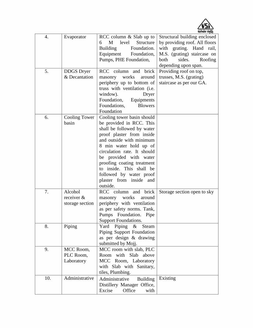
4. Evaporator RCC column & Slab up to
6 M level Structure
Building Foundation.
Equipment Foundation,
Pumps, PHE Foundation,
Structural building enclosed
by providing roof. All floors
with grating. Hand rail,
M.S. (grating) staircase on
both sides. Roofing
depending upon span.
5. DDGS Dryer
& Decantation
RCC column and brick
masonry works around
periphery up to bottom of
truss with ventilation (i.e.
window). Dryer
Foundation, Equipments
Foundations, Blowers
Foundation
Providing roof on top,
trusses, M.S. (grating)
staircase as per our GA.
6. Cooling Tower
basin
Cooling tower basin should
be provided in RCC. This
shall be followed by water
proof plaster from inside
and outside with minimum
8 min water hold up of
circulation rate. It should
be provided with water
proofing coating treatment
to inside. This shall be
followed by water proof
plaster from inside and
outside.
7. Alcohol
receiver &
storage section
RCC column and brick
masonry works around
periphery with ventilation
as per safety norms. Tank,
Pumps Foundation. Pipe
Support Foundations.
Storage section open to sky
8. Piping Yard Piping & Steam
Piping Support Foundation
as per design & drawing
submitted by Mojj.
9. MCC Room,
PLC Room,
Laboratory
MCC room with slab, PLC
Room with Slab above
MCC Room, Laboratory
with Slab with Sanitary,
tiles, Plumbing.
10. Administrative Administrative Building
Distillery Manager Office,
Excise Office with
Existing
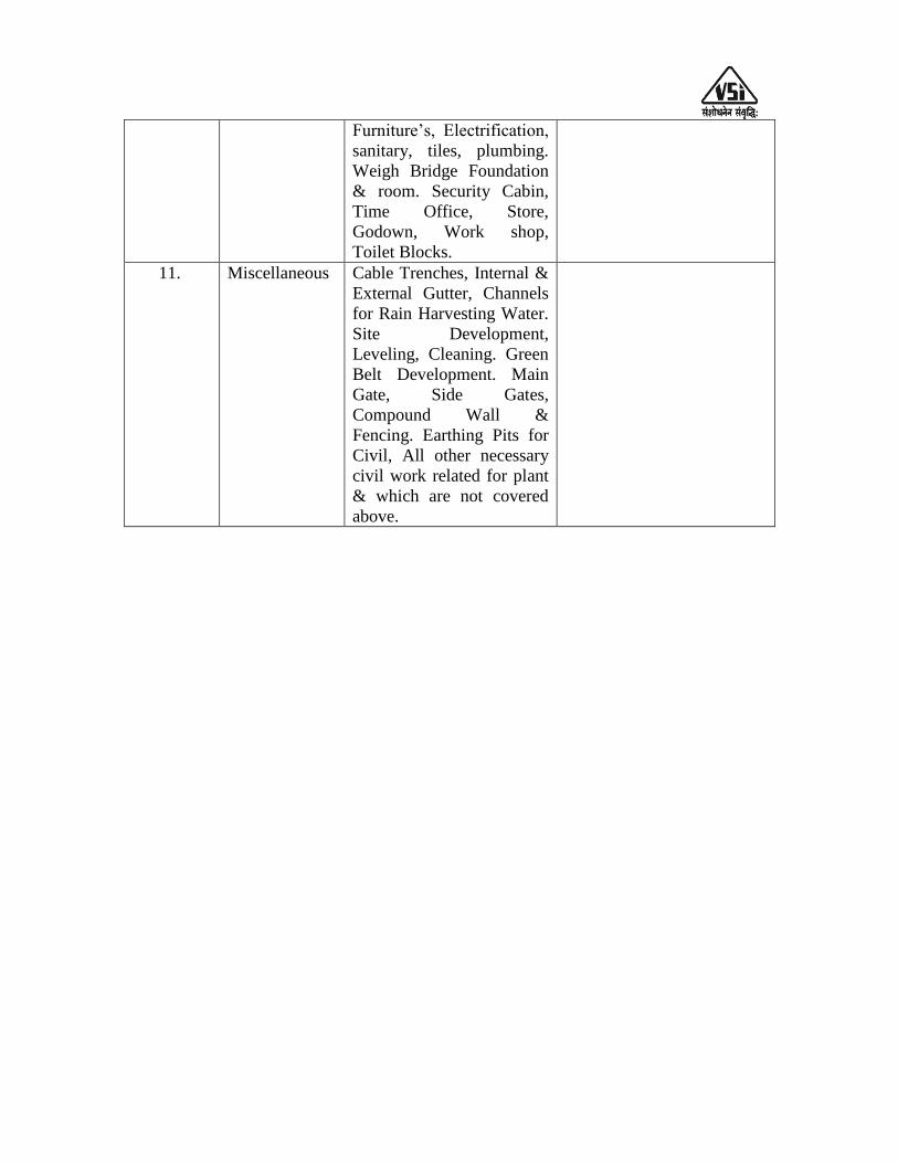
Furniture‟s, Electrification,
sanitary, tiles, plumbing.
Weigh Bridge Foundation
& room. Security Cabin,
Time Office, Store,
Godown, Work shop,
Toilet Blocks.
11. Miscellaneous Cable Trenches, Internal &
External Gutter, Channels
for Rain Harvesting Water.
Site Development,
Leveling, Cleaning. Green
Belt Development. Main
Gate, Side Gates,
Compound Wall &
Fencing. Earthing Pits for
Civil, All other necessary
civil work related for plant
& which are not covered
above.
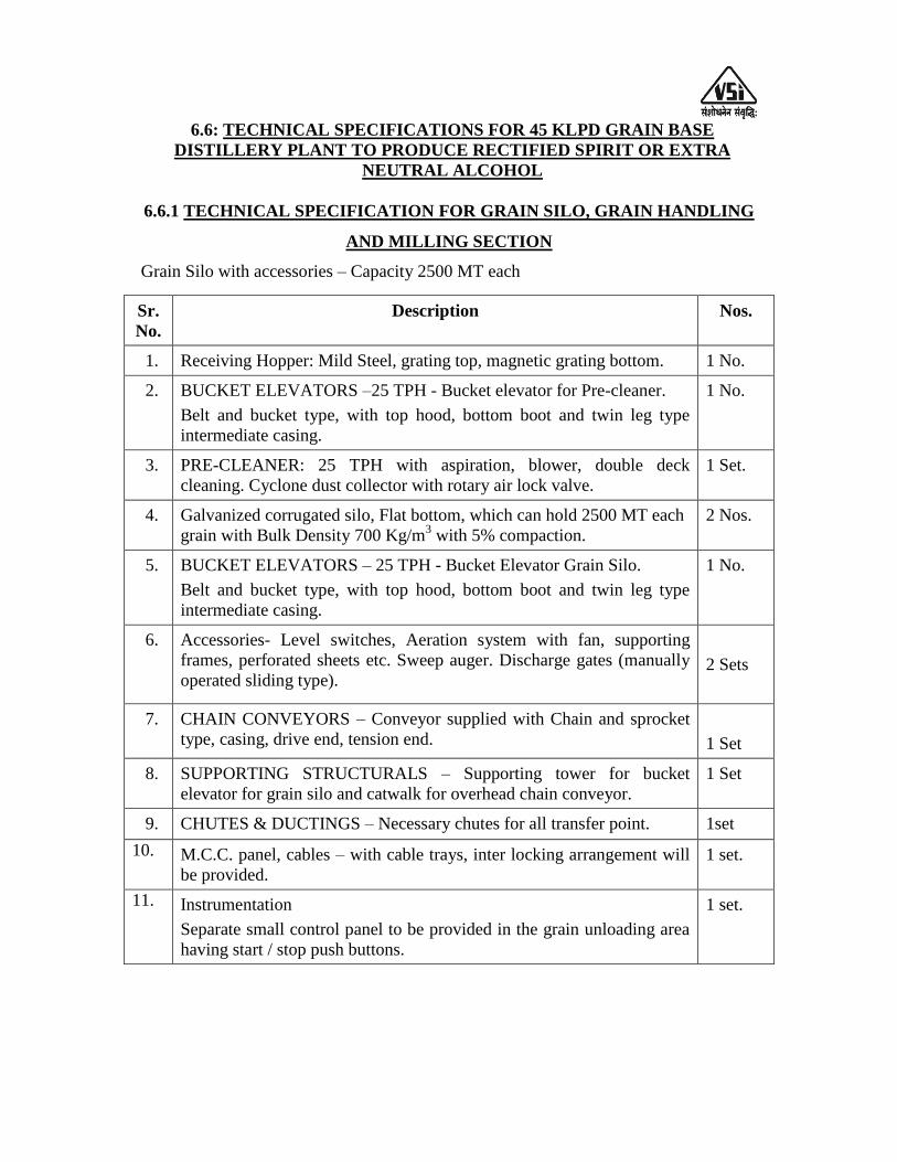
6.6: TECHNICAL SPECIFICATIONS FOR 45 KLPD GRAIN BASE
DISTILLERY PLANT TO PRODUCE RECTIFIED SPIRIT OR EXTRA
NEUTRAL ALCOHOL
6.6.1 TECHNICAL SPECIFICATION FOR GRAIN SILO, GRAIN HANDLING
AND MILLING SECTION
Grain Silo with accessories – Capacity 2500 MT each
Sr.
No.
Description Nos.
1. Receiving Hopper: Mild Steel, grating top, magnetic grating bottom. 1 No.
2. BUCKET ELEVATORS –25 TPH - Bucket elevator for Pre-cleaner.
Belt and bucket type, with top hood, bottom boot and twin leg type
intermediate casing.
1 No.
3. PRE-CLEANER: 25 TPH with aspiration, blower, double deck
cleaning. Cyclone dust collector with rotary air lock valve.
1 Set.
4. Galvanized corrugated silo, Flat bottom, which can hold 2500 MT each
grain with Bulk Density 700 Kg/m3 with 5% compaction.
2 Nos.
5. BUCKET ELEVATORS – 25 TPH - Bucket Elevator Grain Silo.
Belt and bucket type, with top hood, bottom boot and twin leg type
intermediate casing.
1 No.
6. Accessories- Level switches, Aeration system with fan, supporting
frames, perforated sheets etc. Sweep auger. Discharge gates (manually
operated sliding type).
2 Sets
7. CHAIN CONVEYORS – Conveyor supplied with Chain and sprocket
type, casing, drive end, tension end.
1 Set
8. SUPPORTING STRUCTURALS – Supporting tower for bucket
elevator for grain silo and catwalk for overhead chain conveyor.
1 Set
9. CHUTES & DUCTINGS – Necessary chutes for all transfer point. 1set
10. M.C.C. panel, cables – with cable trays, inter locking arrangement will
be provided.
1 set.
11. Instrumentation
Separate small control panel to be provided in the grain unloading area
having start / stop push buttons.
1 set.
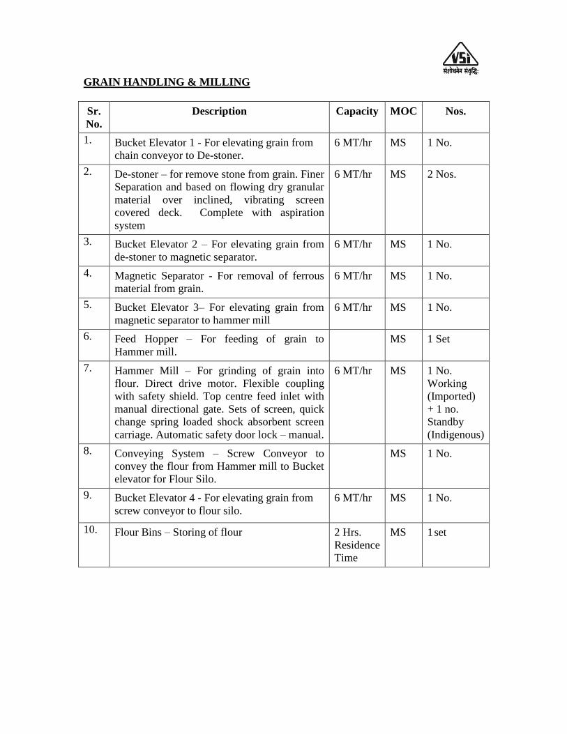
GRAIN HANDLING & MILLING
Sr.
No.
Description Capacity MOC Nos.
1. Bucket Elevator 1 - For elevating grain from
chain conveyor to De-stoner.
6 MT/hr MS 1 No.
2. De-stoner – for remove stone from grain. Finer
Separation and based on flowing dry granular
material over inclined, vibrating screen
covered deck. Complete with aspiration
system
6 MT/hr MS 2 Nos.
3. Bucket Elevator 2 – For elevating grain from
de-stoner to magnetic separator.
6 MT/hr MS 1 No.
4. Magnetic Separator - For removal of ferrous
material from grain.
6 MT/hr MS 1 No.
5. Bucket Elevator 3– For elevating grain from
magnetic separator to hammer mill
6 MT/hr MS 1 No.
6. Feed Hopper – For feeding of grain to
Hammer mill.
MS 1 Set
7. Hammer Mill – For grinding of grain into
flour. Direct drive motor. Flexible coupling
with safety shield. Top centre feed inlet with
manual directional gate. Sets of screen, quick
change spring loaded shock absorbent screen
carriage. Automatic safety door lock – manual.
6 MT/hr MS 1 No.
Working
(Imported)
+ 1 no.
Standby
(Indigenous)
8. Conveying System – Screw Conveyor to
convey the flour from Hammer mill to Bucket
elevator for Flour Silo.
MS 1 No.
9. Bucket Elevator 4 - For elevating grain from
screw conveyor to flour silo.
6 MT/hr MS 1 No.
10. Flour Bins – Storing of flour 2 Hrs.
Residence
Time
MS 1 set
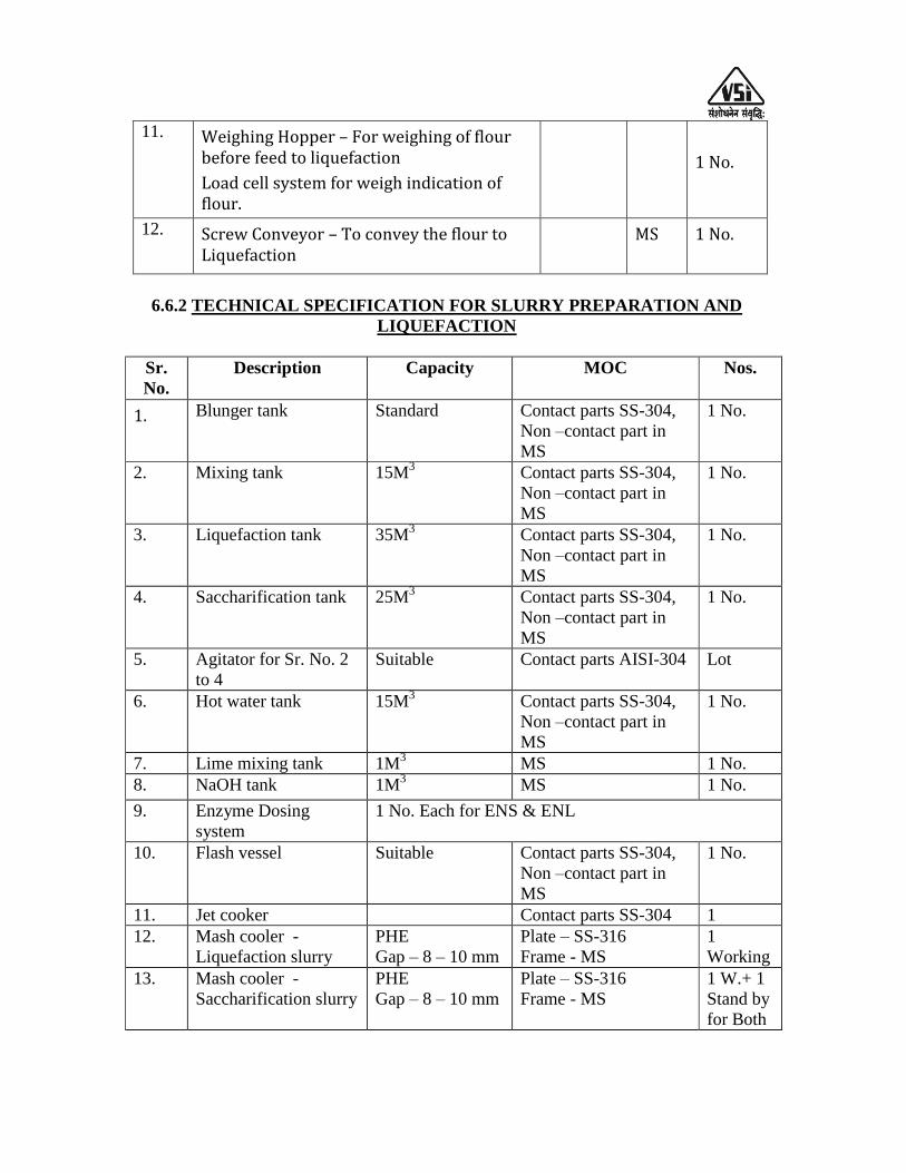
11. Weighing Hopper – For weighing of flour before feed to liquefaction
Load cell system for weigh indication of flour.
1 No.
12. Screw Conveyor – To convey the flour to Liquefaction
MS 1 No.
6.6.2 TECHNICAL SPECIFICATION FOR SLURRY PREPARATION AND
LIQUEFACTION
Sr.
No.
Description Capacity MOC Nos.
1. Blunger tank Standard Contact parts SS-304,
Non –contact part in
MS
1 No.
2. Mixing tank 15M3 Contact parts SS-304,
Non –contact part in
MS
1 No.
3. Liquefaction tank 35M3 Contact parts SS-304,
Non –contact part in
MS
1 No.
4. Saccharification tank 25M3 Contact parts SS-304,
Non –contact part in
MS
1 No.
5. Agitator for Sr. No. 2
to 4
Suitable Contact parts AISI-304 Lot
6. Hot water tank 15M3 Contact parts SS-304,
Non –contact part in
MS
1 No.
7. Lime mixing tank 1M3 MS 1 No.
8. NaOH tank 1M3 MS 1 No.
9. Enzyme Dosing
system
1 No. Each for ENS & ENL
10. Flash vessel Suitable Contact parts SS-304,
Non –contact part in
MS
1 No.
11. Jet cooker Contact parts SS-304 1
12. Mash cooler -
Liquefaction slurry
PHE
Gap – 8 – 10 mm
Plate – SS-316
Frame - MS
1
Working
13. Mash cooler -
Saccharification slurry
PHE
Gap – 8 – 10 mm
Plate – SS-316
Frame - MS
1 W.+ 1
Stand by
for Both
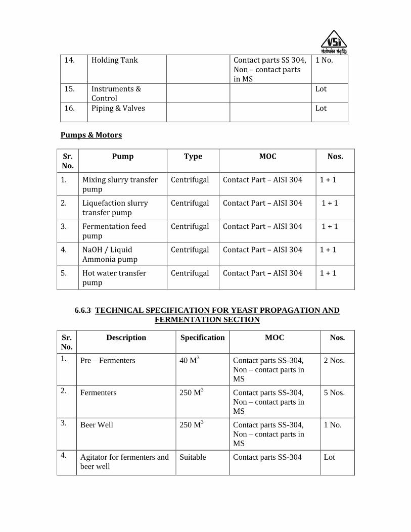
14. Holding Tank Contact parts SS 304, Non – contact parts in MS
1 No.
15. Instruments & Control
Lot
16. Piping & Valves Lot
Pumps & Motors
Sr. No.
Pump Type MOC Nos.
1. Mixing slurry transfer pump
Centrifugal Contact Part – AISI 304 1 + 1
2. Liquefaction slurry transfer pump
Centrifugal Contact Part – AISI 304 1 + 1
3. Fermentation feed pump
Centrifugal Contact Part – AISI 304 1 + 1
4. NaOH / Liquid Ammonia pump
Centrifugal Contact Part – AISI 304 1 + 1
5. Hot water transfer pump
Centrifugal Contact Part – AISI 304 1 + 1
6.6.3 TECHNICAL SPECIFICATION FOR YEAST PROPAGATION AND
FERMENTATION SECTION
Sr.
No.
Description Specification MOC Nos.
1. Pre – Fermenters 40 M3 Contact parts SS-304,
Non – contact parts in
MS
2 Nos.
2. Fermenters 250 M3 Contact parts SS-304,
Non – contact parts in
MS
5 Nos.
3. Beer Well 250 M3 Contact parts SS-304,
Non – contact parts in
MS
1 No.
4. Agitator for fermenters and
beer well
Suitable Contact parts SS-304 Lot

5. CIP Tank 10 M3 Contact parts SS-304,
Non – contact parts in
MS
2 Nos.
6. CO2 Scrubber
Sieve Tray
Contact parts SS-304,
Non – contact parts in
MS
1 No.
7. Pre fermenters cooler PHE
Gap - 4 to 4.5
mm
Plate – SS-316
Frame - MS
2 Nos.
8. Fermented cash cooler PHE
Gap - 4 to 4.5
mm
Plate – SS-316
Frame - MS
5 Nos.
9. Instrumentation 1 set
10. Piping & Valves 1 set
Pumps & Motors
Sr.
No.
Pump Type MOC Nos.
1. Fermented wash recirculation
pump
Centrifugal Contact parts – SS- 304 5+ 1
2. CIP Pump with motor Centrifugal Contact parts – SS- 304 1 + 1
3. Pre-fermenter pump Centrifugal Contact parts – SS- 304 1 + 1
4. Fermented wash transfer pump Centrifugal Contact parts – SS- 304 1 + 1
5. Liquid Ring Blower for
Fermentation
Water
Ring Type
Contact parts – SS- 304 1 + 1

6.6.4: TECHNICAL SPECIFICATION FOR MULTIPRESSURE DISTILLATION
SECTION
COLUMNS
Sr.
No.
Description Specification MOC Nos.
1. CO2 Stripping column Diameter – 950 mm
RH grid 6 Nos.
Contact parts
SS-304
1 No.
2. Stripping column Diameter – 1650 mm
RH grid 22 Nos.
Contact parts
SS-304
1 No.
3. Pre-rectifier Cum Exhaust
column
Pre-rectifier
Diameter – 1550 mm
Bubble Cap 55 Nos.
Exhaust - Dia. – 450 mm
Bubble 12 Nos.
Contact parts
SS-304
1 No.
4. Extraction column Diameter – 1100 mm
Bubble Cap 44 Nos.
Contact parts
SS-304
1 No.
5. Rectifier column Diameter – 1400 mm
Bubble Cap 72 Nos.
Shell – SS
304;
38 Trays SS
304; 34 Trays
DOC
1 No.
6. Refining column Diameter – 900 mm
Bubble Cap 50 Nos.
Shell – DOC,
Trays - DOC
1 No.
7. Fusel Oil column Diameter – 900 mm
Bubble Cap 72 Nos.
Contact parts
SS-304
1 No.
REBOILERS
Sr.
No.
Description Specification MOC Nos.
1. Stripper Reboiler Shell & Tube
Tube – OD 38.1 mm X 1.6
mm thk.
Contact parts
SS-304
1 No.
2. Exhaust Reboiler Shell & Tube
Tube – OD 25.4 mm X 1.6
mm thk.
Contact parts
SS-304
1 No.
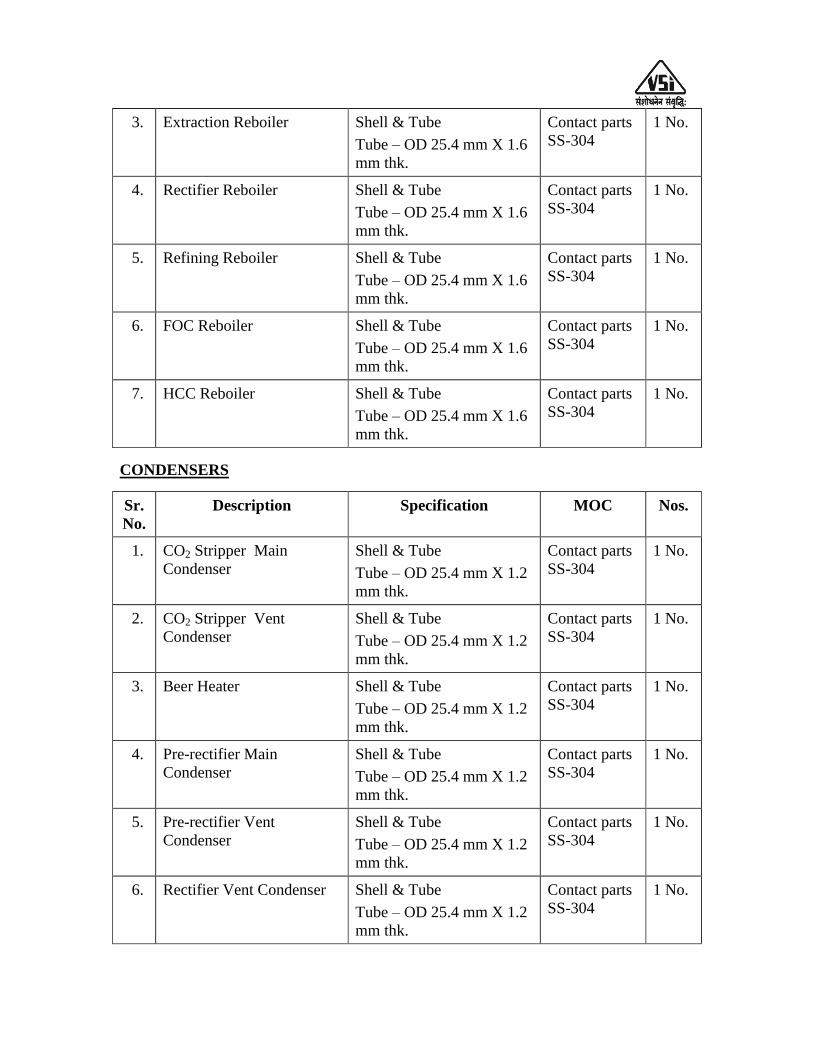
3. Extraction Reboiler Shell & Tube
Tube – OD 25.4 mm X 1.6
mm thk.
Contact parts
SS-304
1 No.
4. Rectifier Reboiler Shell & Tube
Tube – OD 25.4 mm X 1.6
mm thk.
Contact parts
SS-304
1 No.
5. Refining Reboiler Shell & Tube
Tube – OD 25.4 mm X 1.6
mm thk.
Contact parts
SS-304
1 No.
6. FOC Reboiler Shell & Tube
Tube – OD 25.4 mm X 1.6
mm thk.
Contact parts
SS-304
1 No.
7. HCC Reboiler Shell & Tube
Tube – OD 25.4 mm X 1.6
mm thk.
Contact parts
SS-304
1 No.
CONDENSERS
Sr.
No.
Description Specification MOC Nos.
1. CO2 Stripper Main
Condenser
Shell & Tube
Tube – OD 25.4 mm X 1.2
mm thk.
Contact parts
SS-304
1 No.
2. CO2 Stripper Vent
Condenser
Shell & Tube
Tube – OD 25.4 mm X 1.2
mm thk.
Contact parts
SS-304
1 No.
3. Beer Heater Shell & Tube
Tube – OD 25.4 mm X 1.2
mm thk.
Contact parts
SS-304
1 No.
4. Pre-rectifier Main
Condenser
Shell & Tube
Tube – OD 25.4 mm X 1.2
mm thk.
Contact parts
SS-304
1 No.
5. Pre-rectifier Vent
Condenser
Shell & Tube
Tube – OD 25.4 mm X 1.2
mm thk.
Contact parts
SS-304
1 No.
6. Rectifier Vent Condenser Shell & Tube
Tube – OD 25.4 mm X 1.2
mm thk.
Contact parts
SS-304
1 No.
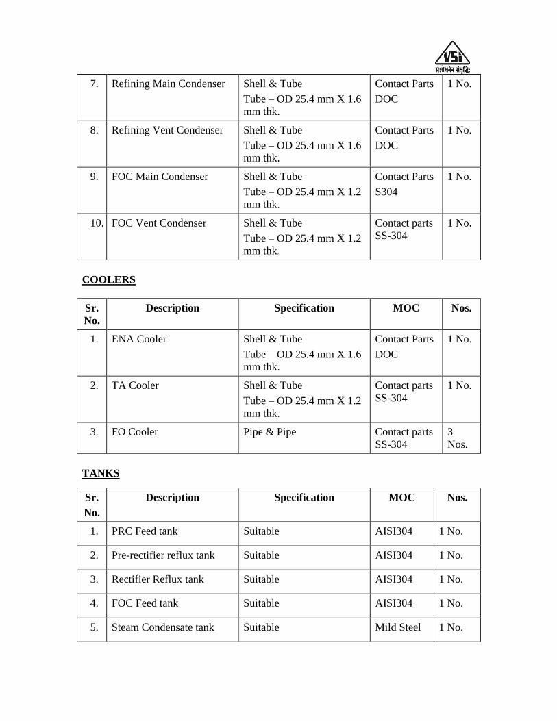
7. Refining Main Condenser Shell & Tube
Tube – OD 25.4 mm X 1.6
mm thk.
Contact Parts
DOC
1 No.
8. Refining Vent Condenser Shell & Tube
Tube – OD 25.4 mm X 1.6
mm thk.
Contact Parts
DOC
1 No.
9. FOC Main Condenser Shell & Tube
Tube – OD 25.4 mm X 1.2
mm thk.
Contact Parts
S304
1 No.
10. FOC Vent Condenser Shell & Tube
Tube – OD 25.4 mm X 1.2
mm thk.
Contact parts
SS-304
1 No.
COOLERS
Sr.
No.
Description Specification MOC Nos.
1. ENA Cooler Shell & Tube
Tube – OD 25.4 mm X 1.6
mm thk.
Contact Parts
DOC
1 No.
2. TA Cooler Shell & Tube
Tube – OD 25.4 mm X 1.2
mm thk.
Contact parts
SS-304
1 No.
3. FO Cooler Pipe & Pipe Contact parts
SS-304
3
Nos.
TANKS
Sr.
No.
Description Specification MOC Nos.
1. PRC Feed tank Suitable AISI304 1 No.
2. Pre-rectifier reflux tank Suitable AISI304 1 No.
3. Rectifier Reflux tank Suitable AISI304 1 No.
4. FOC Feed tank Suitable AISI304 1 No.
5. Steam Condensate tank Suitable Mild Steel 1 No.

6. Fusel Oil Decanter Suitable AISI 304 2 Nos.
MISCELLANEOUS
Sr.
No.
Description Specification MOC Nos.
1. Alcohol Scrubber Packed column AISI 304 1
2. Feed Preheater PHE Plate AISI
304 / Frame
MS
Lot
3. PLC system,
Instrumentation
Lot
4. Piping & Valves Lot
Pumps & Motors
Sr.
No.
Pump Type MOC Nos.
1. CO2 Stripper Reflux pump Centrifugal Contact parts SS-304 1 + 1
2. Stripper Bottom pump Centrifugal Contact parts SS-304 1 + 1
3. Pre-rectifier Reflux pump Centrifugal Contact parts SS-304 1 + 1
4. Extraction Feed pump Centrifugal Contact parts SS-304 1 + 1
5. Rectifier Feed pump Centrifugal Contact parts SS-304 1 + 1
6. Rectifier Reflux pump Centrifugal Contact parts SS-304 1 + 1
7. Rectifier Bottom pump Centrifugal Contact parts SS-304 1 + 1
8. Refining Reflux pump Centrifugal Contact parts SS-304 1 + 1
9. Product Transfer pump Centrifugal Contact parts SS-304 1 + 1
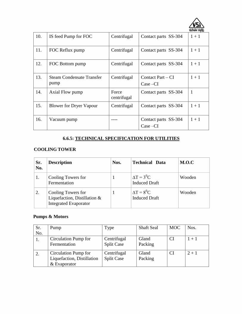
10. IS feed Pump for FOC Centrifugal Contact parts SS-304 1 + 1
11. FOC Reflux pump Centrifugal Contact parts SS-304 1 + 1
12. FOC Bottom pump Centrifugal Contact parts SS-304 1 + 1
13. Steam Condensate Transfer
pump
Centrifugal Contact Part – CI
Case –CI
1 + 1
14. Axial Flow pump Force
centrifugal
Contact parts SS-304 1
15. Blower for Dryer Vapour Centrifugal Contact parts SS-304 1 + 1
16. Vacuum pump ---- Contact parts SS-304
Case –CI
1 + 1
6.6.5: TECHNICAL SPECIFICATION FOR UTILITIES
COOLING TOWER
Sr.
No.
Description Nos. Technical Data M.O.C
1. Cooling Towers for
Fermentation
1 ∆T = 30C
Induced Draft
Wooden
2. Cooling Towers for
Liquefaction, Distillation &
Integrated Evaporator
1 ∆T = 80C
Induced Draft
Wooden
Pumps & Motors
Sr.
No.
Pump Type Shaft Seal MOC Nos.
1. Circulation Pump for
Fermentation
Centrifugal
Split Case
Gland
Packing
CI
1 + 1
2. Circulation Pump for
Liquefaction, Distillation
& Evaporator
Centrifugal
Split Case
Gland
Packing
CI 2 + 1

MISCELLANEOUS
Sr.
No.
Description Technical Data Nos.
1. Air Compressor Type - Reciprocating
Max. Working Pressure – 7 Bar
Air system, Integrated Air dryer
system, Drive Arrangement &
Air Filter.
1 + 1
2. Sealing Water Recycle Systems Tank – Suitable Capacity with
SS 304 Contact Parts, 1 No.
Pump – Suitable Capacity,
Contact part in SS 304, 1 + 1
Nos.,
PHE – Plate in SS 304, End
Frame in Mild Steel, 1 No.
1 Lot
3. Vacuum Water Recycle Systems Tank – Suitable Capacity with
SS 304 Contact Parts, 1 No.
Pump – Suitable Capacity,
Contact part in SS 304, 1 + 1
Nos.,
PHE – Plate in SS 304, End
Frame in Mild Steel, 1 No.
1 Lot
6.6.6: TECHNICAL SPECIFICATION FOR RECEIVER &
STORAGE SECTION
RECEIVERS
Sr.
No.
Description Technical Data M.O.C Nos.
1. Day Receiver Tank for R.S. Type : Vertical /
Cylindrical
Capacity – 50M3
Mild
Steel
3
1. 2. Day Receiver Tank for ENA Type : Vertical /
Cylindrical
Capacity – 50M3
Mild
Steel
3
2. 3. Day Receiver Tank for TA Type : Vertical /
Cylindrical
Capacity – 5M3
Mild
Steel
3

ALCOHOL STORAGE
Sr.
No.
Description Technical Data M.O.C Nos.
1. Bulk Storage Tank for R.S. Type : Vertical /
Cylindrical
Capacity – 700 M3
Mild
Steel
2
2. Bulk Storage Tank for ENA Type : Vertical /
Cylindrical
Capacity – 700 M3
Mild
Steel
2
3. Bulk Storage Tank for TA Type : Vertical /
Cylindrical
Capacity –100 M3
Mild
Steel
1
4. FO Storage Tank Type : Vertical /
Cylindrical
Capacity –10 M3
Mild
Steel
1
ACCESSORIES
Sr.
No.
Description Nos. Technical Data M.O.C
1. 1. Vent Condenser – For Bulk
Storage tanks
1 Lot Shell & Tube Mild Steel
2. 2. Flame Arrestor 1 Lot.
3. Piping & Valves 1 Lot Mild Steel
Pumps & Motors
Sr.
No. Pump
Nos. Type Shaft Seal MOC
4. 1. Issue cum Transfer
pump for R.S./ENA
1 + 1 Centrifugal
40 M3/hr
Single
Mech.
Contact
Parts CF8
5. 2. Issue cum Transfer
pump for IS
1 + 1 Centrifugal
20 M3/hr
Single
Mech.
Contact
Parts CF8
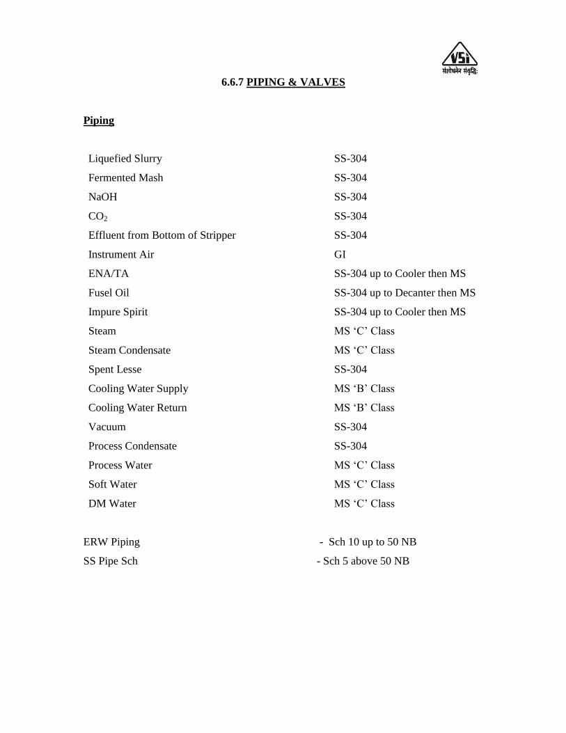
6.6.7 PIPING & VALVES
Piping
Liquefied Slurry
Fermented Mash
NaOH
CO2
Effluent from Bottom of Stripper
Instrument Air
ENA/TA
Fusel Oil
Impure Spirit
Steam
Steam Condensate
Spent Lesse
Cooling Water Supply
Cooling Water Return
Vacuum
Process Condensate
Process Water
Soft Water
DM Water
SS-304
SS-304
SS-304
SS-304
SS-304
GI
SS-304 up to Cooler then MS
SS-304 up to Decanter then MS
SS-304 up to Cooler then MS
MS „C‟ Class
MS „C‟ Class
SS-304
MS „B‟ Class
MS „B‟ Class
SS-304
SS-304
MS „C‟ Class
MS „C‟ Class
MS „C‟ Class
ERW Piping - Sch 10 up to 50 NB
SS Pipe Sch - Sch 5 above 50 NB

Valves
Description Less than 50 NB More than 50 NB
Slurry Ball valve CS body with SS 304
ball
Butterfly valve CI Body &
SS-304 disc.
Fermented Wash Ball valve SS 304 contact parts Butterfly valve with SS-304
disc.
Process & cooling
water
Ball valve with CS body Butterfly valve with CS body
and SGI disc.
Air Ball valve with contact parts
SS304 and Body CS
-
CO2 - Butterfly valve with CI body
and SS-304 disc
Stillage Ball valve SS 304 contact Butterfly valve with CI body
and SS-304 disc
ENA Ball valve SS-304 contact Butterfly valve with CI body
and SS-304 disc
Spent Lesse Ball valve SS-304 contact Butterfly valve with CI body
and SS-304 disc
Steam Condensate Gate valve with CI Body Gate valve with CI Body
Pipe sizing: Velocities to be considered for pipe sizing irrespective of
Pressures are as under-
Steam : 25 – 30 m/sec
Process vapor : 15 - 20 m/sec
Process vapor
Under vacuum : up to 25 m/sec
Pumped liquids : 1.2-1.8 m/sec
Gravity flow : 0.8-0.9 m/sec
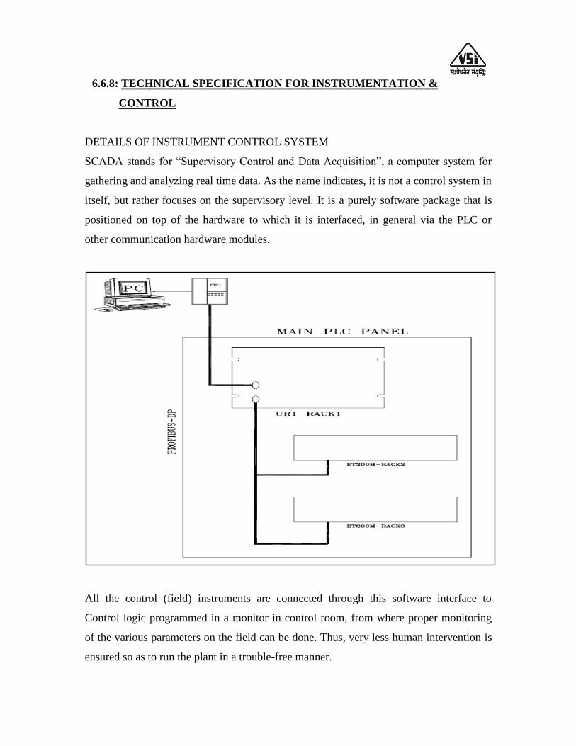
6.6.8: TECHNICAL SPECIFICATION FOR INSTRUMENTATION &
CONTROL
DETAILS OF INSTRUMENT CONTROL SYSTEM
SCADA stands for “Supervisory Control and Data Acquisition”, a computer system for
gathering and analyzing real time data. As the name indicates, it is not a control system in
itself, but rather focuses on the supervisory level. It is a purely software package that is
positioned on top of the hardware to which it is interfaced, in general via the PLC or
other communication hardware modules.
All the control (field) instruments are connected through this software interface to
Control logic programmed in a monitor in control room, from where proper monitoring
of the various parameters on the field can be done. Thus, very less human intervention is
ensured so as to run the plant in a trouble-free manner.
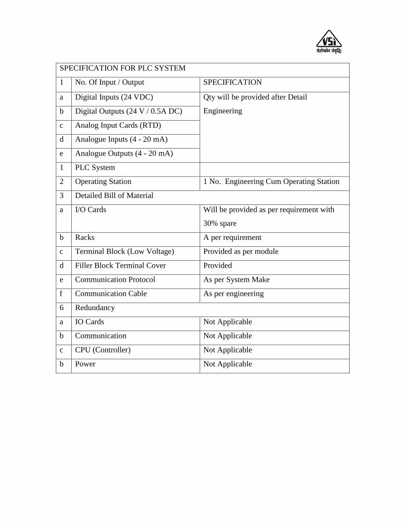
SPECIFICATION FOR PLC SYSTEM
1 No. Of Input / Output SPECIFICATION
a Digital Inputs (24 VDC) Qty will be provided after Detail
Engineering b Digital Outputs (24 V / 0.5A DC)
c Analog Input Cards (RTD)
d Analogue Inputs (4 - 20 mA)
e Analogue Outputs (4 - 20 mA)
1 PLC System
2 Operating Station 1 No. Engineering Cum Operating Station
3 Detailed Bill of Material
a I/O Cards Will be provided as per requirement with
30% spare
b Racks A per requirement
c Terminal Block (Low Voltage) Provided as per module
d Filler Block Terminal Cover Provided
e Communication Protocol As per System Make
f Communication Cable As per engineering
6 Redundancy
a IO Cards Not Applicable
b Communication Not Applicable
c CPU (Controller) Not Applicable
b Power Not Applicable

SPECIFICATIONS FOR ICP PANEL FOR FERMENTATION & DDGS DRYER
INDICATION ONLY
Type Fixed, Free Vertical Standalone Type
Operation Front Operated with Single door, door lock rittal
type
Location Outside. (Open Area In Fermentation Section)
Enclosure Protection IP 52
Cable Entry From Bottom through detachable gland plates,
3mm Thk
Fabrication 14 / 16 G CRCA Sheet
Painting Powder Coating with 7 - Tank Process
Colour Shade Siemens Grey, RAL - 7032
Base Frame 75 mm ISMC
Lifting Lugs To be Provided as Required
Panel Dimensions Suitable
Power Supply 230 VAC, 50 Hz
Control Supply 230 VAC, 50 Hz / 24 VDC
6.6.9: List of Instrumentation
LIQUIFICATION
1
2
3
4
Temp Element
Flow Meters – Glass Tube Rotameters, Metal Tube Rotameters, Magnetic
Flow Meter
Pressure Gauges
Control Loops
Lot
FERMENTATION
1
2
3
Temp Element
Flow Meters – Glass Tube Rotameters, Magnetic Flow Meter
Pressure Gauges
Lot
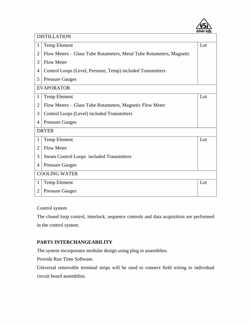
DISTILLATION
1
2
3
4
5
Temp Element
Flow Meters – Glass Tube Rotameters, Metal Tube Rotameters, Magnetic
Flow Meter
Control Loops (Level, Pressure, Temp) included Transmitters
Pressure Gauges
Lot
EVAPORATOR
1
2
3
4
Temp Element
Flow Meters – Glass Tube Rotameters, Magnetic Flow Meter
Control Loops (Level) included Transmitters
Pressure Gauges
Lot
DRYER
1
2
3
4
Temp Element
Flow Meter
Steam Control Loops included Transmitters
Pressure Gauges
Lot
COOLING WATER
1
2
Temp Element
Pressure Gauges
Lot
Control system
The closed loop control, interlock, sequence controls and data acquisition are performed
in the control system.
PARTS INTERCHANGEABILITY
The system incorporates modular design using plug in assemblies.
Provide Run Time Software.
Universal removable terminal strips will be used to connect field wiring to individual
circuit board assemblies.
SECURITY
Memory protect key switch is there to prevent alteration of program and configuration
data through interface device.
SYSTEM SPECIFICATION
System hardware
The system offers following subsystems connected to it.
Communication hardware
– Communication within PLC system
– The system is reliable, high speed, and peer–to–peer communication.
– The BUS of IEEE standard and of latest version.
– The BUS system capable of being extended through a connection of Modem.
– PLC is provided with profibus communication.
– Communication with external device through TCP/IP protocol.
Control system
The closed loop control, interlock, sequence controls and data acquisition are performed
in the control system.
Communication system
PC + Printer
PC
Make – HP/Equivalent
Intel Core I3 Processor / 4 GB RAM / 360 GB HDD
Accessories – Keyboard / Mouse / DVD Writer
Operating System – Windows Xp / Windows 7
Monitor – 21.5 inch LCD
License – User 1 Paper License
Printer with Scanner - 1 No
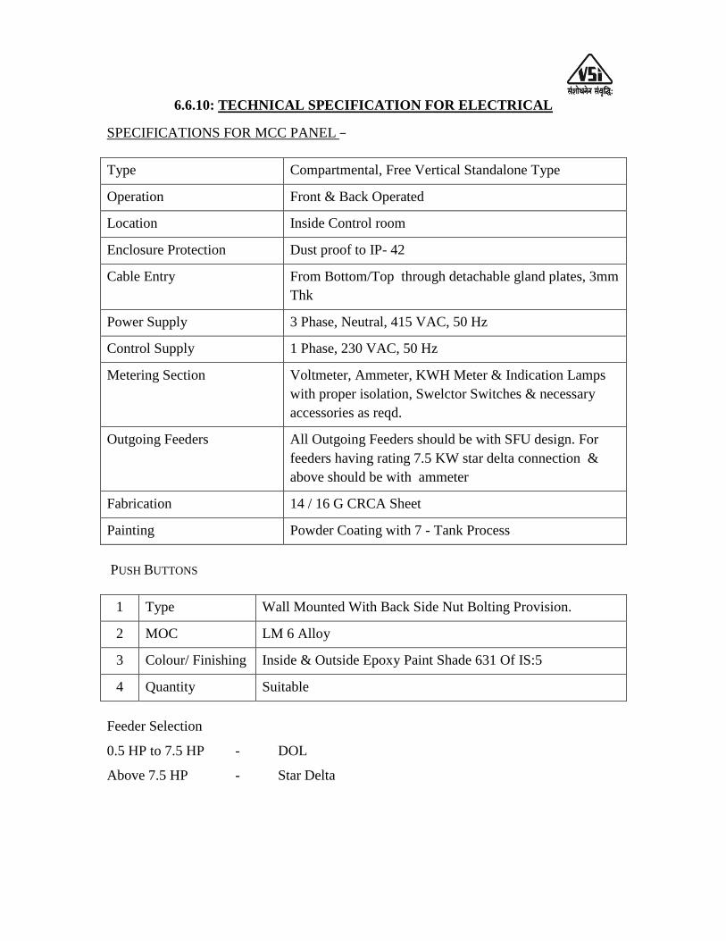
6.6.10: TECHNICAL SPECIFICATION FOR ELECTRICAL SPECIFICATIONS FOR MCC PANEL –
Type Compartmental, Free Vertical Standalone Type
Operation Front & Back Operated
Location Inside Control room
Enclosure Protection Dust proof to IP- 42
Cable Entry From Bottom/Top through detachable gland plates, 3mm
Thk
Power Supply 3 Phase, Neutral, 415 VAC, 50 Hz
Control Supply 1 Phase, 230 VAC, 50 Hz
Metering Section Voltmeter, Ammeter, KWH Meter & Indication Lamps
with proper isolation, Swelctor Switches & necessary
accessories as reqd.
Outgoing Feeders All Outgoing Feeders should be with SFU design. For
feeders having rating 7.5 KW star delta connection &
above should be with ammeter
Fabrication 14 / 16 G CRCA Sheet
Painting Powder Coating with 7 - Tank Process
PUSH BUTTONS
1 Type Wall Mounted With Back Side Nut Bolting Provision.
2 MOC LM 6 Alloy
3 Colour/ Finishing Inside & Outside Epoxy Paint Shade 631 Of IS:5
4 Quantity Suitable
Feeder Selection
0.5 HP to 7.5 HP - DOL
Above 7.5 HP - Star Delta

CABLE SPECIFICATION
Instrument / Control cable
300/500 V Standard non compact tinned Copper Conductor with XLPE insulation,
overall screened with AL MYLAR & DRAIN WIRE, EXTRUDED PVC ST2
INNERSHEATH,SINGLE GI Rounded wire Armour AND PVC ST2 Outer sheath
For 24 & 5 Core Cable, all cores shall be colored Grey & Numbering shall be provided
on each core insulation in Black Letters, for core Identification. For 3 Core Cable, cores
shall be color coded with Brown + Black + Blue. Also for 2 Core Cable, cores shall be
color coded with Blue + White. The same will be applicable for Pair & Triad cable. For
Multi Pair & Triad Cables, all individual pairs / triads should be in Twisted form & with
proper Numbering.
Power cable
C 1.1 KV, Aluminium / Copper Conductor, PVC Insulated, Inner Sheathed, Armoured
& PVC Sheathed cables Conforming to IS:1554 (part I),
1 3 Core up to 2.5 mm2
Copper, Type - YWY
2 3 Core above 2.5 mm2
Aluminium, Type - YWY
For Cables above 200 mtr should be supplied in Drum
Standard Drum length should be of 1000 / 500 mtrs. +/- 5% tolerance OR Single length
+/- 5% tolerance in case of quantity is less than 500 mtr.
Plant & Yard Lighting
Sr. No. Description
1. Plant Lighting
a. LP – WP Well Glass fitting suitable for 160W MLL / 200W GLS / 125W
HPMV lamp in LM6 construction duly epoxy powder coating
b. 125W / 160 W HPMV lamp suitable for sr. no. 1
c. 2 Core X 1.5 mm2
Copper Armoured Cable
d. 3 Core X 1.5 mm2
Copper Flexible Cable
e. Push Button Station WP, On-Off, in Die Cast Al. Alloy within built Cap
f. Junction Box in Aluminium, TYPE : PFC
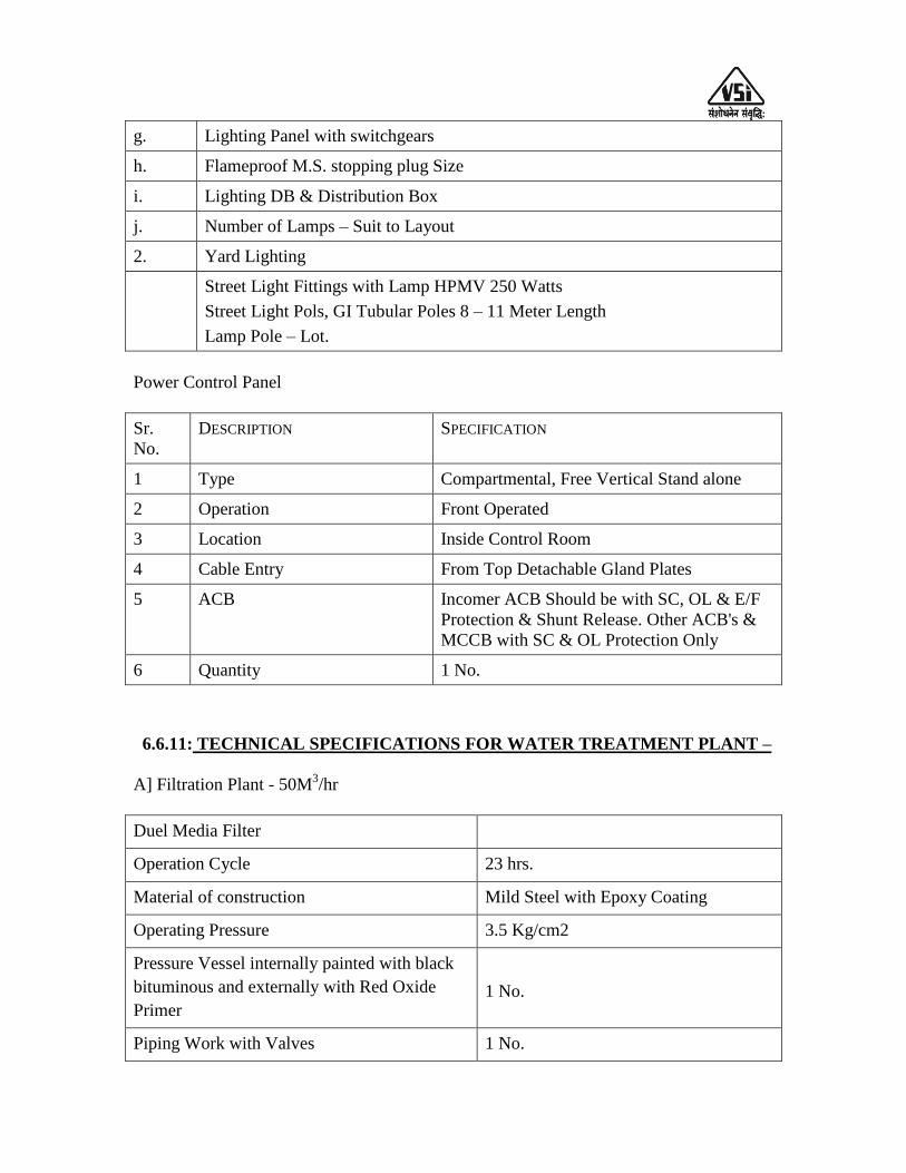
g. Lighting Panel with switchgears
h. Flameproof M.S. stopping plug Size
i. Lighting DB & Distribution Box
j. Number of Lamps – Suit to Layout
2. Yard Lighting
Street Light Fittings with Lamp HPMV 250 Watts
Street Light Pols, GI Tubular Poles 8 – 11 Meter Length
Lamp Pole – Lot.
Power Control Panel
Sr.
No.
DESCRIPTION SPECIFICATION
1 Type Compartmental, Free Vertical Stand alone
2 Operation Front Operated
3 Location Inside Control Room
4 Cable Entry From Top Detachable Gland Plates
5 ACB Incomer ACB Should be with SC, OL & E/F
Protection & Shunt Release. Other ACB's &
MCCB with SC & OL Protection Only
6 Quantity 1 No.
6.6.11: TECHNICAL SPECIFICATIONS FOR WATER TREATMENT PLANT –
A] Filtration Plant - 50M3/hr
Duel Media Filter
Operation Cycle 23 hrs.
Material of construction Mild Steel with Epoxy Coating
Operating Pressure 3.5 Kg/cm2
Pressure Vessel internally painted with black
bituminous and externally with Red Oxide
Primer
1 No.
Piping Work with Valves 1 No.
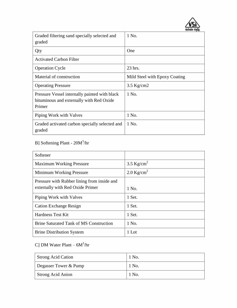
Graded filtering sand specially selected and
graded
1 No.
Qty One
Activated Carbon Filter
Operation Cycle 23 hrs.
Material of construction Mild Steel with Epoxy Coating
Operating Pressure 3.5 Kg/cm2
Pressure Vessel internally painted with black
bituminous and externally with Red Oxide
Primer
1 No.
Piping Work with Valves 1 No.
Graded activated carbon specially selected and
graded
1 No.
B] Softening Plant - 20M3/hr
Softener
Maximum Working Pressure 3.5 Kg/cm2
Minimum Working Pressure 2.0 Kg/cm2
Pressure with Rubber lining from inside and
externally with Red Oxide Primer
1 No.
Piping Work with Valves 1 Set.
Cation Exchange Resign 1 Set.
Hardness Test Kit 1 Set.
Brine Saturated Tank of MS Construction 1 No.
Brine Distribution System 1 Lot
C] DM Water Plant – 6M3/hr
Strong Acid Cation 1 No.
Degasser Tower & Pump 1 No.
Strong Acid Anion 1 No.

Mixed Bed Exchanger 1 No.
Qty 1 No.
6.6.12: Scope of supply for fire hydrant section
Sr.
No.
DESCRIPTION Nos. Unit
SECTION – A
FIRE HYDRANT SYSTEM COMPRISING OF PIPING,,FIRE
HYDRANT VALVES , WATER GUM FOAM MONITOR &
OTHER ACCESSORIES AS MENTIONED BELOW
1. Piping : 01 Lot
2. Single Hydrant Valve : 01 Lot
3. Double Door Hose Cabinet : 01 Lot
4. Canvas Hose for Double door Hose cabinet: 01 Lot
5. Hose Reel Drum with Fire Hose: 01 Lot
6. Water Cum Foam Monitor: 01 Lot
7. Single Hydrant Valve : (SHV) : 01 Lot
8. Double Hydrant Valve : (DHV) : 01 Lot
9. Canvas Hose for single door hose cabinet : 01 Lot
10. Single Door Hose Cabinet: 01 Lot
SECTION – B
SIAMESE INLET & BREACH CONNECTIONS
11. Breach Inlet connection 01 Lot
12. Siamese Breaching Assembly 01 Lot
SECTION – C
PUMP ROOM COMPONENTS :
FIRE PUMP AND ITS ACCESSORIES
13. Electric Driven Centrifugal Pump : 01 Lot
Hydrant pump 01 Lot

Jockey pump
14. Diesel Pump Suitable for Above - Kirloskar 01 Lot
15. POWER CABLES - required for above pumps to control panel 01 Lot
16 MCC Panel: 01 Lot
17. Air Vessel : 01 Lot
18. Non-Return Valve : 01 Lot
19. Butterfly Valve: 01 Lot
20. Accessories for Pump (Applicable only if it is negative Suction ) :
21. Pressure Switch : 01 Lot
SECTION – D Lot
22. FIRE EXTINGUISHER & BUCKETS Lot
22.1 CO2 type Fire Extinguisher 01
22.2 ABC Stored Pressure type Fire Extinguisher 01 Lot
22.3 ABC Stored Pressure type Fire Extinguisher 4 Kgs. 01 Lot
22.4 AFFF M Foam type Fire extinguishers 01 Lot
22.5 AFFF M Foam type Fire extinguishers 01 Lot
22.6 Fire Bucket with Support Stand ( 6 buckets –one stand ) 01 Lot
6.6.13: SPECIFICATIONS FOR BOILER, TURBINE, PRDS, DG SET, STEAM
PIPING
A. BOILER
Design code IBR 1950 with latest amendments
Steam capacity Kg/hr 18000
Steam pressure Kg/cm2 (g) 45
Steam temperature C 490 ± 5
Feed Water Temp. C 105
Main fuel for boiler Coal / rice Husk as supporting fuel or 100%
Coal/Bagasse.
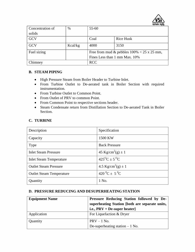
Concentration of
solids
% 55-60
GCV Coal Rice Husk
GCV Kcal/kg 4000 3150
Fuel sizing Free from mud & pebbles 100% < 25 x 25 mm,
Fines Less than 1 mm Max. 10%
Chimney RCC
B. STEAM PIPING
High Pressure Steam from Boiler Header to Turbine Inlet.
From Turbine Outlet to De-aerated tank in Boiler Section with required
instrumentation.
From Turbine Outlet to Common Point.
From Outlet of PRV to common Point.
From Common Point to respective sections header.
Steam Condensate return from Distillation Section to De-aerated Tank in Boiler
Section.
C. TURBINE
Description Specification
Capacity 1500 KW
Type Back Pressure
Inlet Steam Pressure 45 Kg/cm2(g) ± 1
Inlet Steam Temperature 425OC ± 5
OC
Outlet Steam Pressure 4.5 Kg/cm2(g) ± 1
Outlet Steam Temperature 420 0C ± 5
0C
Quantity 1 No.
D. PRESSURE REDUCING AND DESUPERHEATING STATION
Equipment Name Pressure Reducing Station followed by De-
superheating Station [both are separate units,
i.e., PRV + De-super heater]
Application For Liquefaction & Dryer
Quantity PRV – 1 No.
De-superheating station – 1 No.
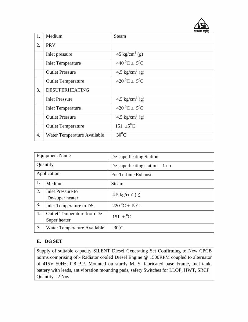
1. Medium Steam
2. PRV
Inlet pressure 45 kg/cm2 (g)
Inlet Temperature 440 0C ± 5
0C
Outlet Pressure 4.5 kg/cm2 (g)
Outlet Temperature 420 0C ± 5
0C
3. DESUPERHEATING
Inlet Pressure 4.5 kg/cm2 (g)
Inlet Temperature 420 0C ± 5
0C
Outlet Pressure 4.5 kg/cm2 (g)
Outlet Temperature 151 ±50C
4. Water Temperature Available 300C
Equipment Name De-superheating Station
Quantity De-superheating station – 1 no.
Application For Turbine Exhaust
1. Medium Steam
2. Inlet Pressure to
De-super heater 4.5 kg/cm
2 (g)
3. Inlet Temperature to DS 220 0C ± 5
0C
4. Outlet Temperature from De-
Super heater 151 ±
0C
5. Water Temperature Available 300C
E. DG SET
Supply of suitable capacity SILENT Diesel Generating Set Confirming to New CPCB
norms comprising of:- Radiator cooled Diesel Engine @ 1500RPM coupled to alternator
of 415V 50Hz; 0.8 P.F. Mounted on sturdy M. S. fabricated base Frame, fuel tank,
battery with leads, ant vibration mounting pads, safety Switches for LLOP, HWT, SRCP
Quantity - 2 Nos.
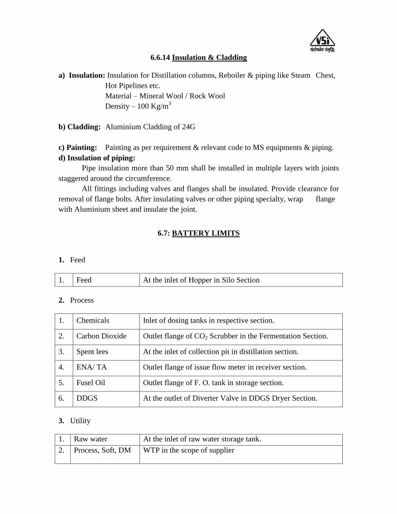
6.6.14 Insulation & Cladding
a) Insulation: Insulation for Distillation columns, Reboiler & piping like Steam Chest,
Hot Pipelines etc.
Material – Mineral Wool / Rock Wool
Density – 100 Kg/m3
b) Cladding: Aluminium Cladding of 24G
c) Painting: Painting as per requirement & relevant code to MS equipments & piping.
d) Insulation of piping:
Pipe insulation more than 50 mm shall be installed in multiple layers with joints
staggered around the circumference.
All fittings including valves and flanges shall be insulated. Provide clearance for
removal of flange bolts. After insulating valves or other piping specialty, wrap flange
with Aluminium sheet and insulate the joint.
6.7: BATTERY LIMITS
1. Feed
1. Feed At the inlet of Hopper in Silo Section
2. Process
1. Chemicals Inlet of dosing tanks in respective section.
2. Carbon Dioxide Outlet flange of CO2 Scrubber in the Fermentation Section.
3. Spent lees At the inlet of collection pit in distillation section.
4. ENA/ TA Outlet flange of issue flow meter in receiver section.
5. Fusel Oil Outlet flange of F. O. tank in storage section.
6. DDGS At the outlet of Diverter Valve in DDGS Dryer Section.
3. Utility
1. Raw water At the inlet of raw water storage tank.
2. Process, Soft, DM
water
WTP in the scope of supplier
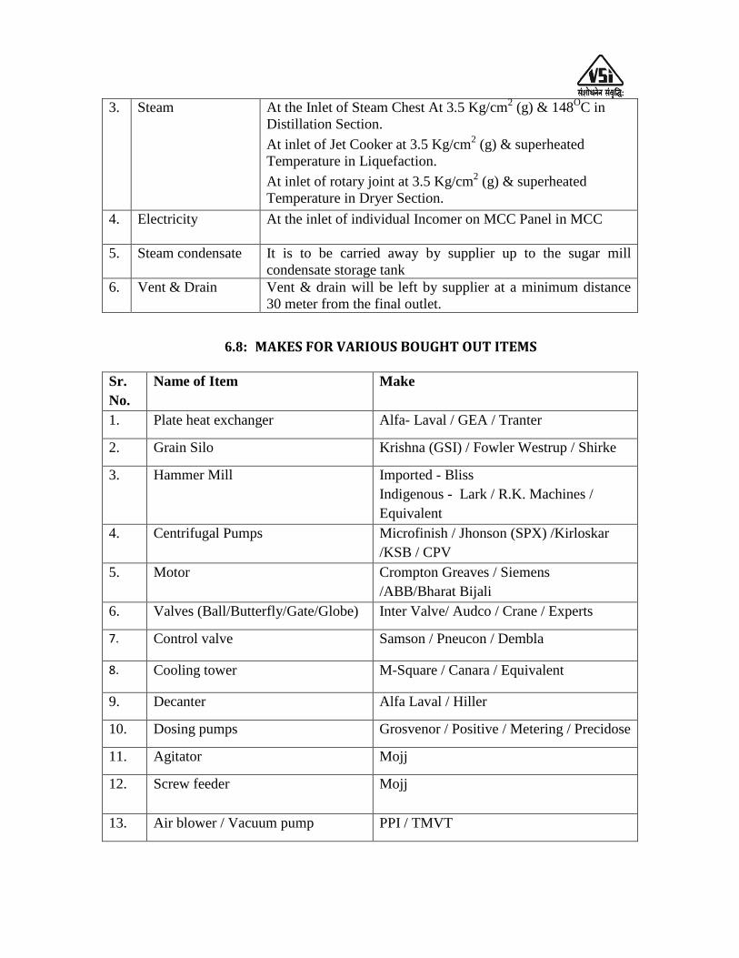
3. Steam At the Inlet of Steam Chest At 3.5 Kg/cm2 (g) & 148
OC in
Distillation Section.
At inlet of Jet Cooker at 3.5 Kg/cm2 (g) & superheated
Temperature in Liquefaction.
At inlet of rotary joint at 3.5 Kg/cm2 (g) & superheated
Temperature in Dryer Section.
4. Electricity At the inlet of individual Incomer on MCC Panel in MCC
Room nea
5. Steam condensate It is to be carried away by supplier up to the sugar mill
condensate storage tank
6. Vent & Drain Vent & drain will be left by supplier at a minimum distance
30 meter from the final outlet.
6.8: MAKES FOR VARIOUS BOUGHT OUT ITEMS
Sr.
No.
Name of Item Make
1. Plate heat exchanger Alfa- Laval / GEA / Tranter
2. Grain Silo Krishna (GSI) / Fowler Westrup / Shirke
3. Hammer Mill Imported - Bliss
Indigenous - Lark / R.K. Machines /
Equivalent
4. Centrifugal Pumps Microfinish / Jhonson (SPX) /Kirloskar
/KSB / CPV
5. Motor Crompton Greaves / Siemens
/ABB/Bharat Bijali
6. Valves (Ball/Butterfly/Gate/Globe) Inter Valve/ Audco / Crane / Experts
7. Control valve Samson / Pneucon / Dembla
8. Cooling tower M-Square / Canara / Equivalent
9. Decanter Alfa Laval / Hiller
10. Dosing pumps Grosvenor / Positive / Metering / Precidose
11. Agitator Mojj
12. Screw feeder
Mojj
13. Air blower / Vacuum pump PPI / TMVT
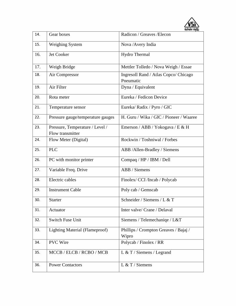
14. Gear boxes Radicon / Greaves /Elecon
15. Weighing System Nova /Avery India
16. Jet Cooker Hydro Thermal
17. Weigh Bridge Mettler Tolledo / Nova Weigh / Essae
18. Air Compressor Ingresoll Rand / Atlas Copco/ Chicago
Pneumatic
19. Air Filter Dyna / Equivalent
20. Rota meter Eureka / Fedicon Device
21. Temperature sensor Eureka/ Radix / Pyro / GIC
22. Pressure gauge/temperature gauges H. Guru / Wika / GIC / Pioneer / Waaree
23. Pressure, Temperature / Level /
Flow transmitter
Emerson / ABB / Yokogava / E & H
24. Flow Meter (Digital) Rockwin / Toshniwal / Forbes
25. PLC ABB /Allen-Bradley / Siemens
26. PC with monitor printer Compaq / HP / IBM / Dell
27. Variable Freq. Drive ABB / Siemens
28. Electric cables Finolex/ CCI /Incab / Polycab
29. Instrument Cable Poly cab / Gemscab
30. Starter Schneider / Siemens / L & T
31. Actuator Inter valve/ Crane / Delaval
32. Switch Fuse Unit Siemens / Telemechaniqe / L&T
33. Lighting Material (Flameproof)
Phillips / Crompton Greaves / Bajaj /
Wipro
34. PVC Wire Polycab / Finolex / RR
35. MCCB / ELCB / RCBO / MCB
L & T / Siemens / Legrand
36. Power Contactors L & T / Siemens
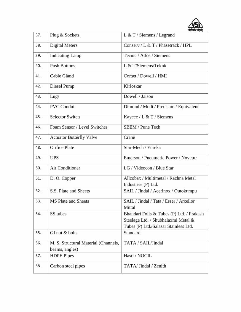
37. Plug & Sockets L & T / Siemens / Legrand
38. Digital Meters Conserv / L & T / Phasetrack / HPL
39. Indicating Lamp Tecnic / Atlos / Siemens
40. Push Buttons L & T/Siemens/Teknic
41. Cable Gland Comet / Dowell / HMI
42. Diesel Pump Kirloskar
43. Lugs Dowell / Jaison
44. PVC Conduit Dimond / Modi / Precision / Equivalent
45. Selector Switch Kaycee / L & T / Siemens
46. Foam Sensor / Level Switches SBEM / Pune Tech
47. Actuator Butterfly Valve Crane
48. Orifice Plate Star-Mech / Eureka
49. UPS Emerson / Pneumeric Power / Novetur
50. Air Conditioner LG / Videocon / Blue Star
51. D. O. Copper Allcobax / Multimetal / Rachna Metal
Industries (P) Ltd.
52. S.S. Plate and Sheets SAIL / Jindal / Acerinox / Outokumpu
53. MS Plate and Sheets SAIL / Jindal / Tata / Esser / Arcellor
Mittal
54. SS tubes Bhandari Foils & Tubes (P) Ltd. / Prakash
Steelage Ltd. / Shubhalaxmi Metal &
Tubes (P) Ltd./Salasar Stainless Ltd.
55. GI nut & bolts Standard
56. M. S. Structural Material (Channels,
beams, angles)
TATA / SAIL/Jindal
57. HDPE Pipes Hasti / NOCIL
58. Carbon steel pipes TATA/ Jindal / Zenith
CHAPTER – VII: TREATMENT OF EFFLUENT
The mother liquor left behind after distilling-off alcohol is called as stillage. The
stillage of distillery poses a very serious problem by way of threat to the
environment.
The VSSSKL management has decided to install new 45 KLPD grain based
distillery plant to produce R.S. or ENA. Sugar mill management has also decided to
install Decantation section, Multiple Effect Evaporation section, Mingler section to
produce Distiller‟s Wet Grains with Solubles (DWGS), Steam Tube Dryer to produce
Distiller‟s Dried Grains with Solubles (DDGS) and standalone multiple effect spentwash
evaporation plant as primary effluent treatment system followed by Up-flow Anaerobic
Sludge Blanket (UASB) digester for treatment of process condensates, CIP effluents,
Boiler & Cooling tower blow downs, Fermenter washing water etc. In UASB digester
COD & BOD % values are reduced and biogas produced, which is used as a fuel in
boiler.
The effluent coming out of the UASB digester is further treated in the polishing
aerobic reactor to bring down the BOD as per the norms of pollution control authorities
and then can be used for ferti-irrigation purpose.
Decantation section: The alcohol stripped whole stillage or spent mash or thick stillage
coming out of distillation section is subjected to decantation by centrifugation to separate
the suspended fibrous mass called wet cake and thin stillage. Wet cake has about 30 %
w/w total solids as removed from the bottom of the decanter and can be directly loaded
on the trolleys. Wet cake can be used directly in the formulation of animal feed.
Otherwise, wet cake is taken to the mingler for further processing.
Composition of Wet cake and thin slops are given in Table 7.1 and 2.2,
respectively.

Table 7.1: Composition of Grains & Wet cake (after decantation)
Sr. No Contents Sorghum Rice / Broken rice
Grains Wet cake Grains Wet cake
1 Total solids 87 - 91 28 - 32.0 88 - 90 28 - 30.0
2 Moisture 9 - 13 68 - 72 10 - 12 70 - 72
3 Starch 64 - 70 1.9 - 2.1 65 - 70 1.9 - 2.1
4 Proteins 7 - 11.0 7 - 11.0 4 - 7.0 4 - 7.0
5 Oils/Fats 2.2 - 3.2 2.2 - 3.2 0.4 - 1.0 0.4 - 1.0
6 Crude fibers 3.3 - 4.1 3.3 - 4.1 0.8 - 1.6 1.0 - 1.7
7 Inorganic ash 1.0 - 1.6 1.1 - 1.6 0.4 - 1.2 0.45 - 1.3
Table 7.2: Composition of Thin Slop
Sr. No. Parameters Values
1 Flow 200-300 M3/day (after decantation)
2 Total solids (T.S.) 9 - 10 % (W/W)
3 COD 50-60,000 Mg/Lit.
4 BOD 30 - 35,000 Mg/Lit.
5 T.S.S. 15,200 - 16,000 Mg/Lit. (Max.)
6 Temperature 38 - 40 C
7 pH 4.5 - 5.0
Table 7.3: Technical specification for stillage recycling system
Sr.
No.
Description Specification MOC Nos.
1. Decanter Horizontal
Centrifugal
Contact parts-SS 316 1 + 1
2. Raw Stillage tank 30M3 MS with Epoxy paint 1 No.
3. Thin Stillage tank 65M3 MS with Epoxy paint 1 No.
4. Conc. Stillage tank 10M3 Contact parts SS 1 No.

304,
Non – contact pars in
MS
5. Piping and valves As per process Standard 1 lot
6. Instrumentation & Control As per process Standard 1 lot
Pumps & Motors:
Sr.
No.
Pump Type MOC Nos.
1. Raw Stillage feed pump Centrifugal Contact part – SS-304
1 + 1
2. Thin Stillage pump Centrifugal Contact part – SS-304
1 + 1
3. Conc. Stillage Feed pump Centrifugal Contact part – SS-304
1 + 1
7.4: Technical specification for stillage evaporator
Evaporators are classified by the number of effects. In a single-effect evaporator,
steam provides energy for vaporization and the vapor product is condensed and removed
from the system. In a double-effect evaporator, the vapor product off the first effect is
used to provide energy for a second vaporization unit. Triple- effect evaporator, the vapor
product off the second effect is used to provide energy for a third vaporization unit. This
cascading of effects can continue for many stages. For special applications, Multiple-
effect evaporators consisting of even 12 effects have been designed. Multiple-effect
evaporators can remove much larger amounts of solvent than is possible in a single
effect.
In a multiple effect arrangement, the latent heat of the vapor product off of an
effect is used to heat the following effect. Effects are thus numbered beginning with the
one heated by steam. It will have the highest pressure. Vapor from Effect I will be used to
heat Effect II, which consequently will operate at lower pressure. This continues through
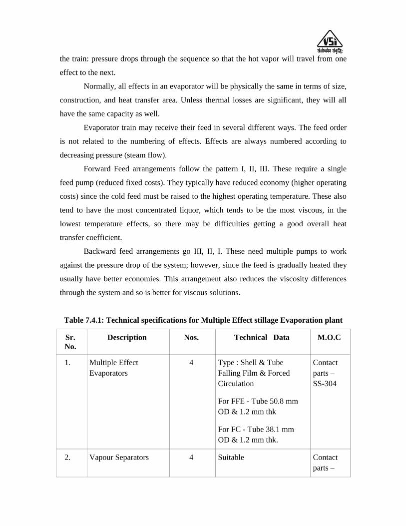
the train: pressure drops through the sequence so that the hot vapor will travel from one
effect to the next.
Normally, all effects in an evaporator will be physically the same in terms of size,
construction, and heat transfer area. Unless thermal losses are significant, they will all
have the same capacity as well.
Evaporator train may receive their feed in several different ways. The feed order
is not related to the numbering of effects. Effects are always numbered according to
decreasing pressure (steam flow).
Forward Feed arrangements follow the pattern I, II, III. These require a single
feed pump (reduced fixed costs). They typically have reduced economy (higher operating
costs) since the cold feed must be raised to the highest operating temperature. These also
tend to have the most concentrated liquor, which tends to be the most viscous, in the
lowest temperature effects, so there may be difficulties getting a good overall heat
transfer coefficient.
Backward feed arrangements go III, II, I. These need multiple pumps to work
against the pressure drop of the system; however, since the feed is gradually heated they
usually have better economies. This arrangement also reduces the viscosity differences
through the system and so is better for viscous solutions.
Table 7.4.1: Technical specifications for Multiple Effect stillage Evaporation plant
Sr.
No.
Description Nos. Technical Data M.O.C
1. Multiple Effect
Evaporators
4 Type : Shell & Tube
Falling Film & Forced
Circulation
For FFE - Tube 50.8 mm
OD & 1.2 mm thk
For FC - Tube 38.1 mm
OD & 1.2 mm thk.
Contact
parts –
SS-304
2. Vapour Separators 4 Suitable Contact
parts –
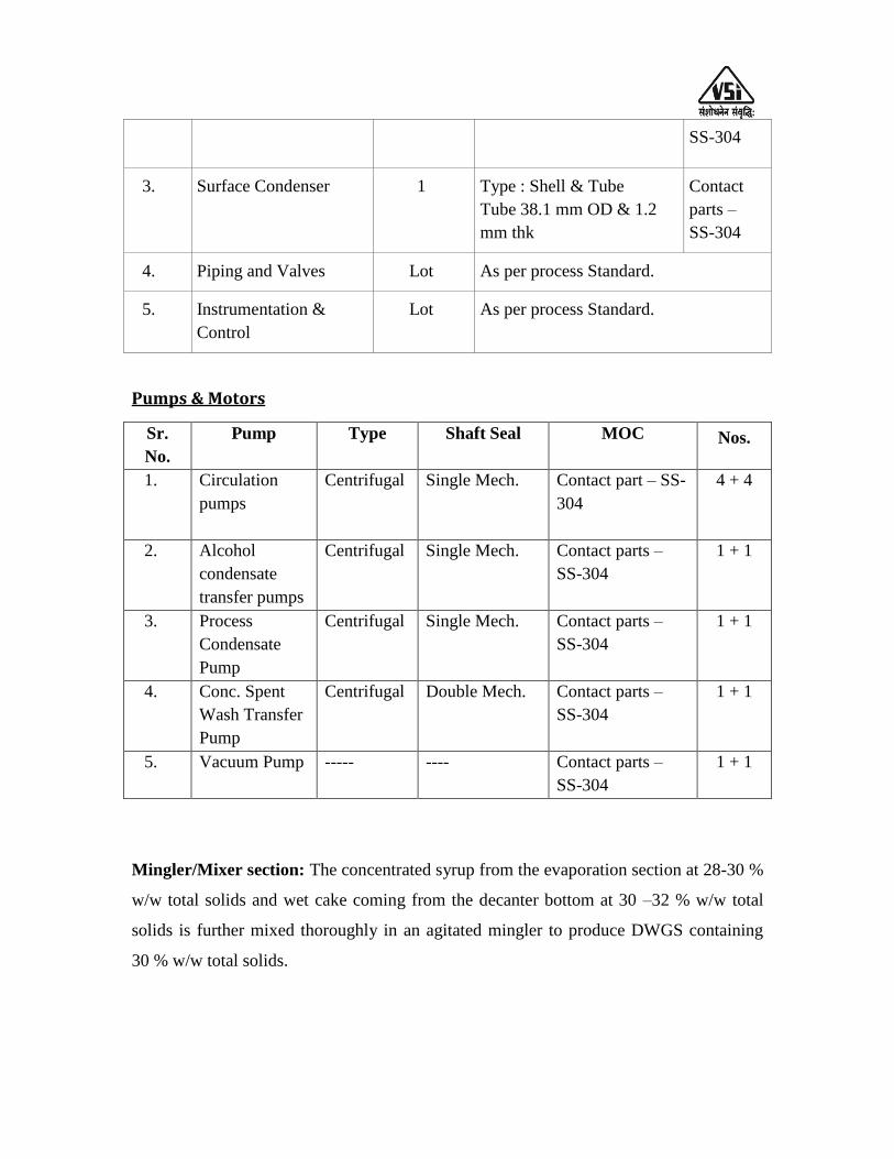
SS-304
3. Surface Condenser 1 Type : Shell & Tube
Tube 38.1 mm OD & 1.2
mm thk
Contact
parts –
SS-304
4. Piping and Valves Lot As per process Standard.
5. Instrumentation &
Control
Lot As per process Standard.
Pumps & Motors
Sr.
No.
Pump Type Shaft Seal MOC Nos.
1. Circulation
pumps
Centrifugal Single Mech. Contact part – SS-
304
4 + 4
2. Alcohol
condensate
transfer pumps
Centrifugal Single Mech. Contact parts –
SS-304
1 + 1
3. Process
Condensate
Pump
Centrifugal Single Mech. Contact parts –
SS-304
1 + 1
4. Conc. Spent
Wash Transfer
Pump
Centrifugal Double Mech. Contact parts –
SS-304
1 + 1
5. Vacuum Pump ----- ---- Contact parts –
SS-304
1 + 1
Mingler/Mixer section: The concentrated syrup from the evaporation section at 28-30 %
w/w total solids and wet cake coming from the decanter bottom at 30 –32 % w/w total
solids is further mixed thoroughly in an agitated mingler to produce DWGS containing
30 % w/w total solids.
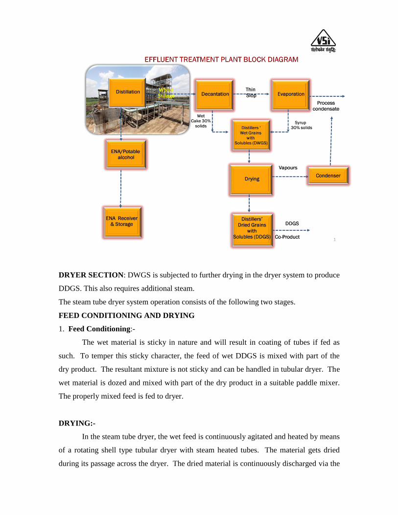
DRYER SECTION: DWGS is subjected to further drying in the dryer system to produce
DDGS. This also requires additional steam.
The steam tube dryer system operation consists of the following two stages.
FEED CONDITIONING AND DRYING
1. Feed Conditioning:-
The wet material is sticky in nature and will result in coating of tubes if fed as
such. To temper this sticky character, the feed of wet DDGS is mixed with part of the
dry product. The resultant mixture is not sticky and can be handled in tubular dryer. The
wet material is dozed and mixed with part of the dry product in a suitable paddle mixer.
The properly mixed feed is fed to dryer.
DRYING:-
In the steam tube dryer, the wet feed is continuously agitated and heated by means
of a rotating shell type tubular dryer with steam heated tubes. The material gets dried
during its passage across the dryer. The dried material is continuously discharged via the
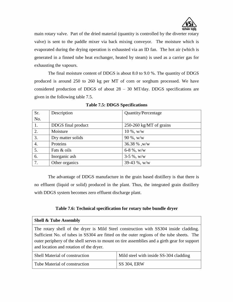
main rotary valve. Part of the dried material (quantity is controlled by the diverter rotary
valve) is sent to the paddle mixer via back mixing conveyor. The moisture which is
evaporated during the drying operation is exhausted via an ID fan. The hot air (which is
generated in a finned tube heat exchanger, heated by steam) is used as a carrier gas for
exhausting the vapours.
The final moisture content of DDGS is about 8.0 to 9.0 %. The quantity of DDGS
produced is around 250 to 260 kg per MT of corn or sorghum processed. We have
considered production of DDGS of about 28 – 30 MT/day. DDGS specifications are
given in the following table 7.5.
Table 7.5: DDGS Specifications
Sr.
No.
Description Quantity/Percentage
1. DDGS final product 250-260 kg/MT of grains
2. Moisture 10 %, w/w
3. Dry matter solids 90 %, w/w
4. Proteins 36.38 % ,w/w
5. Fats & oils 6-8 %, w/w
6. Inorganic ash 3-5 %, w/w
7. Other organics 39-43 %, w/w
The advantage of DDGS manufacture in the grain based distillery is that there is
no effluent (liquid or solid) produced in the plant. Thus, the integrated grain distillery
with DDGS system becomes zero effluent discharge plant.
Table 7.6: Technical specification for rotary tube bundle dryer
Shell & Tube Assembly
The rotary shell of the dryer is Mild Steel construction with SS304 inside cladding.
Sufficient No. of tubes in SS304 are fitted on the outer regions of the tube sheets. The
outer periphery of the shell serves to mount on tire assemblies and a girth gear for support
and location and rotation of the dryer.
Shell Material of construction Mild steel with inside SS-304 cladding
Tube Material of construction SS 304, ERW

Nos. 1 No
Drive Arrangement
Drive motor rotates the dryer through a drive train of pulleys, V belts, gearbox, flexible
coupling and pinion / girth gear assembly. All drive components are mounted on a
common M.S. base frame.
Feed Section
Wet cake & concentrated Stillage from Grain plant mixed in a Feed conditioner followed
by screw conveyor which is fed in dryer through a stationary cover located at a central
cut-out on the tube sheet.
Vapour Exhaust
On the stationary COVER on the discharge side, there is an exhaust port which is to be
connected to cyclone separator in SS304 contact parts with Rotary air lock & exhaust fan
for exhaust of vapors to atmosphere. MOC of ducting SS 304 Contact parts.
Vapour Blower
A centrifugal blower driven by a TEFC motor through V belt and pulleys is provided.
The blower is statically dynamically balanced.
Type Centrifugal
Drive Belt Driven
Material of Construction Impeller : SS-304
Casing : SS-304
Post Drying
The Product from Rotary Dryer is fed to Post Drying System to achieve 10% - 12%
w/w moisture Content in DDGS. The Material of Constriction SS-304 for Contact
Parts. Non-Contact Parts are in Mild Steel.
Product Discharge
At the end of the rotary shell, near the steam supply end, there are ports for
discharge of the feed into a fixed receiver. Product is collected from the bottom of
the receiver, at an elevation from finished floor level. This product from rotary dryer
will be fed to post drying section thru a screw conveyor in carbon steel. The final
product from post drying section will be collect from discharge Rotary valve below
twin cyclone separator in carbon steel. Material of Construction – Mild Steel

Discharge Screw & Bucket Elevator
Product from rotary dryer feed to post drying section through screw conveyor
followed by bucket elevator. Material of Construction – Mild Steel.
Non Condensable
Non condensable in steam are vented to atmosphere through suitable vents, valves,
from the steam manifold.
Access
The cut-out is large enough for partial manual access into the dryer for cleaning and
maintenance as and when required.
Cyclone Separator
High efficiency twin cyclone separator is provided for separating the product from
exhaust air and exhaust vapours. The product is discharged through a discharge
Rotary valve at the bottom of the cyclone.
Type Tangential Entry
Material of Construction Mild Steel for Product
Support Bracket Carbon Steel
Accessories Inspection / cleaning hand hole, support
bracket, Vortex breaker, Discharge Valve, U-
tube manometer.
Rotary Air Lock Valves (construction) –
A motorized rotary air lock valve is fitted to discharge the dry powder through the chute.
Material of Construction
Housing Aluminium
Rotor Carbon Steel
Ducting from Post Dryer to collection cyclone in Mild Steel. Vapour ducting from rotary
dryer to vapour cyclone in SS-304
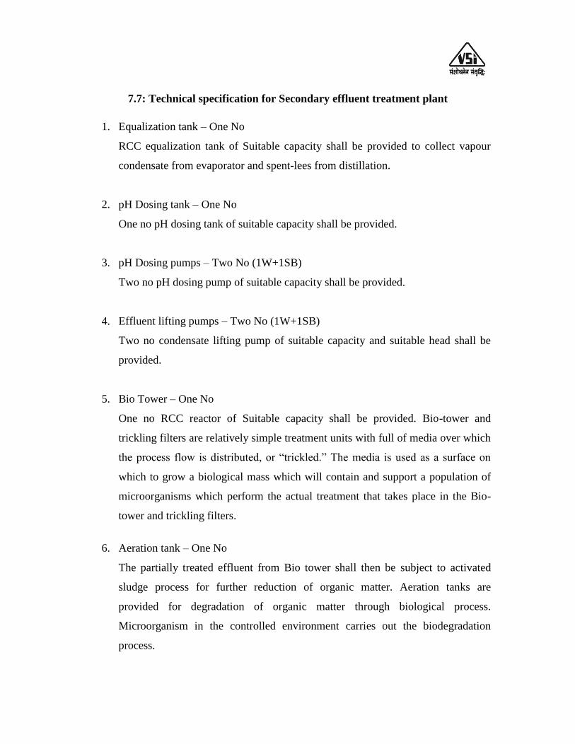
7.7: Technical specification for Secondary effluent treatment plant
1. Equalization tank – One No
RCC equalization tank of Suitable capacity shall be provided to collect vapour
condensate from evaporator and spent-lees from distillation.
2. pH Dosing tank – One No
One no pH dosing tank of suitable capacity shall be provided.
3. pH Dosing pumps – Two No (1W+1SB)
Two no pH dosing pump of suitable capacity shall be provided.
4. Effluent lifting pumps – Two No (1W+1SB)
Two no condensate lifting pump of suitable capacity and suitable head shall be
provided.
5. Bio Tower – One No
One no RCC reactor of Suitable capacity shall be provided. Bio-tower and
trickling filters are relatively simple treatment units with full of media over which
the process flow is distributed, or “trickled.” The media is used as a surface on
which to grow a biological mass which will contain and support a population of
microorganisms which perform the actual treatment that takes place in the Bio-
tower and trickling filters.
6. Aeration tank – One No
The partially treated effluent from Bio tower shall then be subject to activated
sludge process for further reduction of organic matter. Aeration tanks are
provided for degradation of organic matter through biological process.
Microorganism in the controlled environment carries out the biodegradation
process.
7. Blower – I – Two Nos.
Two no blowers (1 Working + 1 Standby) of suitable capacity shall be provided
to facilitate aeration in aeration tank-I.
8. Treated Water Sump- One No.
One no RCC pre-treated water sump of suitable capacity shall be provided to
collect the treated water.
9. Treated Water transfer pump – Two No (1w+1SB)
Two no filter feed pump of suitable capacity shall be provided to feed multigrade
filter.
10. Multi-grade Filter – One No
One No suitable capacity multi-grade filter shall be provided to remove
suspended solids in treated water. Its internals shall be fabricated of carbon steel.
11. Activated Carbon Filter – One No
One no suitable capacity activated carbon filter shall be provided to adsorb the
impurities from treated water. Its internals shall be fabricated of carbon steel.
7.8: Technical specifications membrane treatment plant
Micron Filtration System - 1 Set.
Max. Working Pressure : 3.5 kg /cm2
M.O.C. Of Housing : FRP
MEMBRANE – 1No.
High Pressure pump : Vertical Multistage SS Pump
Quantity : 1nos.
Pressure tube : FRP
Skid : MS Coated with Powder paint
C.I.P. System with SS Pump

CHAPTER –VIII: PERSONNEL REQUIREMENT
VSSSKL is having existing molasses based 60 KLPD Distillery plant based on
Continuous fermentation and MPR distillation system. To exploit more benefit from this
industrial complex, the management of the sugar mill has decided to install new 45
KLPD grain based distillery plant, stillage evaporation plant and secondary effluent
treatment system to achieve “Zero Liquid Discharge” (ZLD) as per CPCB/MPCB norms.
The management of VSSSKL has also decided to install 18 MT/hr @ 45 Kg/cm2 pressure
boiler and 1.5 MW TG set for 45 KLPD grain based distillery plant.
VSSSKL distillery plant is under Administrative Control of Managing Director of
the sugar mill and they have already appointed Distillery Manager, Distillery Chemists,
Lab. Chemists, and Operators for fermentation and distillation section, other skilled and
unskilled workers for their existing 60 KLPD distillery plant.
Existing distillery staff will not be able to operate the new 45 KLPD grain based
distillery plant and effluent treatment systems. Therefore, there is requirement to appoint
additional staff for distillery plant and effluent treatment systems as well as operation.
The section wise requirement of staff and workers and their estimated salary and
wages are given in the following table.
Additional staff salary and wages-
A) For 45 KLPD Grain based distillery plant staff salary and wages-
Sr. No.
Designation No. of Posts Total Annual Salary
(Rs. Lac)
1. Distillery Sr. Chemist 01 4.00
2. Distillery Chemist 03 10.00
3. Assistant Engineer (Elect./Mech.) 01 3.00
4. Lab. Chemist 3+1 9.60
5. Milling plant-Operator 04 10.66
6. Liquefaction plant-Attendant 03 6.00
7. Fermentation process attendant 03 6.00

8. Distillation plant - Operator 04 10.67
9. Distillation process attendant 03 6.00
10. Evaporation plant operator 04 10.67
11. Evaporation plant attendant 03 6.00
12. DDGS and Decantation plant
operator
03 6.00
13. Decantation plant attendant 03 8.00
14. DDGS plant attendant 03 6.00
15. Ware house Attendant 02 4.00
16. Pump Attendant 03 6.00
17. Laboratory Attendant 02 4.00
18. Peon 01 2.00
19. Helper 04 6.00
Total (A) 46 124.60
B) For Condensate Polishing Unit (CPU) -
Sr. No.
Designation No. of Posts Total Annual Salary
(Rs. Lac)
1 Plant Operators 03 8.00
2 Helper 02 3.00
Total (B) 05 11.00
C) For Boiler section –
Sr. No.
Designation No. of Posts Total Annual Salary
(Rs. Lac)
1 Maintenance Engineer 04 14.40
2 Senior DCS Operator 03 9.00
3 Assistant DCS Operator 04 9.60
4 Worker 12 10.08
Total (C) 23 43.08
D) For Turbine section –
Sr. No.
Designation No. of Posts Total Annual Salary
(Rs. Lac)
1 Turbine attendant 03 5.40
2 Assistant turbine attendant 04 4.80
3 Worker 04 3.36
Total (D) 11 13.56
Total (A+B+C+D) (Rs. Lac) 192.24
CONCLUSIONS AND RECOMMENDATIONS
1. The feasibility report is prepared based on information provided by VSSSKL to
the Institute.
2. The new 45 KLPD grain based distillery plant is to be based on latest technology
to produce Rectified Spirit or Extra Neutral Alcohol.
3. The total requirement of grain is 34,085 MT for proposed 45 KLPD grain based
distillery plant considering working for 300 days per annum (100% capacity
utilization). The VSSSKL will purchase grain quantity 34,085 MT from nearby
market.
4. The total investment for 45 KLPD grain based distillery plant based on
multipressure distillation technology, Stillage evaporation, DDGS dryer,
Secondary effluent treatment system, boiler (steam production capacity 18MT/hr,
steam pressure @45 Kg/cm2), T.G. set (1.50 MW/hr), civil & structural works
including taxes and duties shall be Rs. 6,532.82 Lacs.
5. Special arrangement for water treatment should be undertaken depending on raw
water quality.
6. The technical specifications included in this feasibility report are based on
information supplied by Plant supplier‟s to the sugar mill. Institute has updated it
from time to time. However, it will be guideline and may change/improve further
depending on quality.
7. Some of the inputs and utilities are available with the sugar mill. It needs to be
discussed thoroughly at the time of inviting and technical discussion before
negotiation and finalization of order.
8. It is recommended to operate the distillery throughout the year (300 days/annum).
For this purpose special boiler (18 MT/hr, 45 Kg/cm2 g) and new T.G. set (1.50
MW) has been recommended for meeting the requirement of steam and power
and to achieve “Zero Liquid Discharge” of stillage.
9. As regards effluent treatment; modern method of decantation followed by
evaporation and followed by dryer will result in total conversion of stillage in to
animal feed (either as DWGS or DDGS). For other effluents such as process

condensate, spentlees, boiler / cooling tower blow down water, vacuum pump/
pump gland cooling water etc. a secondary effluent treatment system is required
so as to achieve “ZLD” as per CPCB norms.
10. Based on the performance of the proposed distillery plant, mentioned in earlier
chapters, financial parameters are computed which are mentioned below:-
Capacity Utilization of Distillery plant 100 %
Internal Rate of Return (IRR) 13.73 %
Break Even Point (BEP) 76.58 %
Payback period 4 years
Debt Service Coverage Ratio (DSCR)
Average 1.65
Maximum 2.09
Minimum 1.25
11. The earlier discussions on technical configurations and financial parameters in
foregoing chapters reveal that this project is technically feasible and financially
viable. The financial projection indicates higher percentage of profits, sufficient
cash generations to repay the loan with interest. All the financial parameters
normally considered for financing the project are quite favorable. We conclude
that the proposal in the present form is technically feasible, financially viable and
so can be considered favorably for financing.
LIST OF DISTILLERY PLANT SUPPLIERS
* Praj Industries Limited,
Praj Tower, 274/75,
Hinjawadi, Lonkar Chowk,
Phase-III, Pune.
Ph. No.- 020-22951511, 22952214
Fax – 020 – 22951515 / 22951718.
* Mojj Engineering System Limited,
81-B/15, M.I.D.C., Bhosari,
Pune – 411026. (M.S.)
Ph. No. 020-27120835, 27122837, 27122838
Fax No. 020-27127198
* KBK Chem Engg. Pvt. Ltd.,
KBK-House, I -Dot Complex, Survey No. 13/3/7
NDA Pashan Road, Near Maratha Mandir Hall
Bavdhan Khurd, Pune-411021
Ph. No. 020-22953685
Fax No. 020-22951939
* Naran Lala Pvt. Limited,
Post Box No. 20,
Near Railway Station,
Navsari – 396445, (G.S.)
Ph. No. 02637-250371/256192
Fax No. 02637-252092
* Raj Process Equip. and Systems Pvt. Ltd.,
Jai Ganesh Vision, B wing, 3rd
floor,
Jai Ganesh Fame Building, Akurdi, Pune
Ph. No.- 020- 40710010
Fax – 020- 40710009.
Universal Forces Industries Ltd,
“Universal Center”
Plot No. 130C, Sec. No. 10, PCNTDA,
Bhosari, Pune-411026.
Ph. No. 020-66339672/27690744
Fax No. 020-66339673
Meru Industries,
S-31, T Block, Near Pawana Industrial Complex
MIDC, Bhosari, Pune-411026
Ph. No.- 020- 27110181, 27119308
Fax – 020- 27122948.
MULTIPLE EFFECT EVAPORATION PLANT
SUPPLIERS
* S. S. Techno Services Pvt. Limited,
502, Mayfair Tower I, Wakdewadi,
Shivajinagar, Pune-411005.
Ph. No.- 020- 66524431/32/33
Fax – 020- 66524434.
* SSP (Pvt.) Limited,
13, Milestone, Mathura Road,
Faridabad – 121003 (Haryana)
Ph. No.- 0129-2275968, 2277442
Fax – 0129 – 2277441.
* Mojj Engineering System Limited,
81-B/15, M.I.D.C., Bhosari,
Pune – 411026. (M.S.)
Ph. No.- 020-27120835, 27122837, 27122838
Fax – 020 – 27127198.
* Praj Industries Limited,
Praj Tower, 274/75,
Hinjawadi, Lonkar Chowk,
Phase-III, Pune.
Ph. No.- 020-22951511, 22952214
Fax – 020 – 22951515 / 22951718.

* Raj Process Equip. and Systems Pvt. Ltd.,
Jai Ganesh Vision, B wing, 3rd
floor,
Jai Ganesh Fame Building, Akurdi, Pune
Ph. No.- 020- 40710010
Fax – 020- 40710009.
* Naran Lala Pvt. Limited,
Post Box No. 20,
Near Railway Station,
Navsari – 396445, (G.S.)
Ph. No. 02637-250371/256192
Fax No. 02637-252092
* Meru Industries,
S-31, T Block, Near Pawana Industrial Complex
MIDC, Bhosari, Pune-411026
Ph. No.- 020- 27110181, 27119308
Fax – 020- 27122948.
LIST OF SECONDARY ETP PLANT SUPPLIERS
* M M Enviro Projects Pvt. Ltd.,
Aakanksha Arcade, KDK College Road,
Nandanvan, Nagpur-440009
Ph. No. - +91-712-2714960
Fax No. - +91-712-2714968
* Global Enviro Tech. Services,
Flat No. 704, “A” wing,
Kalparukha Jawalkar Nagar,
Kashid Park, Pimple Gurav,
Pune-411061.
Ph. No. 7875157070
* Water Treatment Equipments,
Sr. No. 80/1, Bhosari-Alandi Road,
Behind Hotel Pragati, Wadmukhwadi,
Charholi (Bk), Pune-412105,
Ph. No. 020-32009688,
email- [email protected]
* Praj Industries Limited,
Praj Tower, 274/75,
Hinjawadi, Lonkar Chowk,
Phase-III, Pune.
Ph. No.- 020-22951511, 22952214
Fax – 020 – 22951515 / 22951718.
* Naran Lala Pvt. Limited,
Post Box No. 20,
Near Railway Station,
Navsari – 396445, (G.S.)
Ph. No. 02637-250371/256192
Fax No. 02637-252092
* ATE Enviro Tech. Pvt. Ltd.,
49A/47A Ist floor, Virwani Industrial Estate,
Western Express highway,
Goregaon (East), Mumbai-400063.
Ph. No. 022-29271818 / 29271717
INCINERATION BOILER SUPPLIERS
Chima Boilers
S.C.O. 523-524, Sector-70
Mohali, Chandigarh-160071
Fax :0172-5090486
Mr. Kumar Buch
(Luz-Hou, Thermal Power Equipment Company Ltd.)
6, Soubhagyanagar,Vihitgaon-Lam Road,
Nasik Road-422101
Telphpne- (0253 )-2451275
Thermax Babcock & Wilcox
Division of Thermax Ltd.,
D-1MIDC, R. D. Aga Road,
Chinchwad, Pune-411019
Kind Attn:Mr.John Alwaris
Fax: 020-27479200
Fives-Cail KCP Ltd.,
Ramkrishna Building
No.2, Dr. P. V. Cherian Crescent
Egome, Chennai-600008,
Tel:91 44 66772755, Fax: 91 44 66772799
SSP (Pvt.) Limited,
13, Milestone, Mathura Road,
Faridabad – 121003 (Haryana)
Ph. No.- 0129-2275968, 2277442
Fax – 0129 – 2277441.
ISGEC John Thompson
A-7, Sector 63,
Noida – 201301
U. P.
Email:- [email protected]
LIST OF C.P.U. PLANT SUPPLIERS
* M M Enviro Projects Pvt. Ltd.,
Aakanksha Arcade, KDK College Road,
Nandanvan, Nagpur-440009
Ph. No. - +91-712-2714960
Fax No. - +91-712-2714968
* Global Enviro Tech. Services,
Flat No. 704, “A” wing,
Kalparukha Jawalkar Nagar,
Kashid Park, Pimple Gurav,
Pune-411061.
Ph. No. 7875157070
* Water Treatment Equipments,
Sr. No. 80/1, Bhosari-Alandi Road,
Behind Hotel Pragati, Wadmukhwadi,
Charholi (Bk), Pune-412105,
Ph. No. 020-32009688,
email- [email protected]
* Praj Industries Limited,
Praj Tower, 274/75,
Hinjawadi, Lonkar Chowk,
Phase-III, Pune.
Ph. No.- 020-22951511, 22952214
Fax – 020 – 22951515 / 22951718.
* Naran Lala Pvt. Limited,
Post Box No. 20,
Near Railway Station,
Navsari – 396445, (G.S.)
Ph. No. 02637-250371/256192
Fax No. 02637-252092