
HP Pavilion x2 Detachable Notebook PC HP Split x2 Detachable PC

USER inStRUctionS 1
© copyright 2010, DB industries, inc.
A capital Safety company
4
Certificate No. FM 39709
I S O9 0 0 1 AnSi Z359
AnSi A14.3
En 353-1:2002
cSA Z259.2.13
x1cE tYPE tESt
no. 0320tUV nEL
East Kilbride, GlasgowG75 0QU
UK
cEPRoDUction
QUALitY contRoL
no. 0086BSi Product Services
Kitemark HouseMayland Ave.
Hemel HempsteadHP2 4SQ UK
10
11
ANSI, CSA Ce DeSCRIPTION
6116541 (AnSi A14.3, cSA Z259.2.1)
Flex Sleeve, 8.0 mm or 9.5 mm (5/16” or 3/8”), Sleeve only
6116540 (AnSi A14.3, cSA Z259.2.1)
Flex Sleeve, 8.0 mm or 9.5 mm (5/16” or 3/8”), w/carabiner
6116507 (cSA Z259.2.1)
6116507 (En353-1:2002)
Flex Sleeve, 8.0 mm or 9.5 mm (5/16” or 3/8”), w/Shock Pack & carabiner
FoRM no: 5903085 REV: A
lAD-SAf®
Detachable Cable Sleeve
Model number: 6116507, 6116540, 6116541
2
3


3
FORWARD
this instruction describes installation and use of Lad-Saf® Flexible Detachable cable Sleeve. it should be used as part of an employee training program as required by oSHA, AnSi, cSA, cE, and AS/nZS.
WARNING: These instructions must be provided to all users and rescuers1. The user and installer of this equipment must read and understand these instructions before use of this equipment. Follow the manufacturer’s instructions for safety equipment used with this system. Follow these instructions for proper use, inspection, and maintenance of this equipment. This equipment is intended to be used as part of a complete LAD-SAF® ladder safety system. Alterations, substitutions, or misuse of this equipment, or failure to follow instructions, may result in serious injury or death
IMPORTANT: If you have questions on the installation, use, maintenance, or suitability of this equipment for your application, contact DBI-SALA.
IMPORTANT: Before using this equipment, record the product identification information from the installation and service label in the Inspection & Maintenance Log in Section 9 of this manual.
3
GlOSSARY RefeReNCe BOXeSnumbered Glossary Reference Boxes on the front cover of this instruction reference the following items:
1 : User instructions 2 : Lad-Saf Detachable cable Sleeve 3 : Model number(s) 4 : Standards 5 : top Bracket 6 : cable 7 : cable Guide 8 : System Label with i-Safe™ RFiD tag 9 : Bottom
Bracket 10 : Ec test Performed 11 : number of body checking the manufacture of this PPE
1 RESCUER: Person or persons other than the rescue subject acting to perform an assisted rescue by operation or a rescue system.
4
1.0 APPLICATIONS
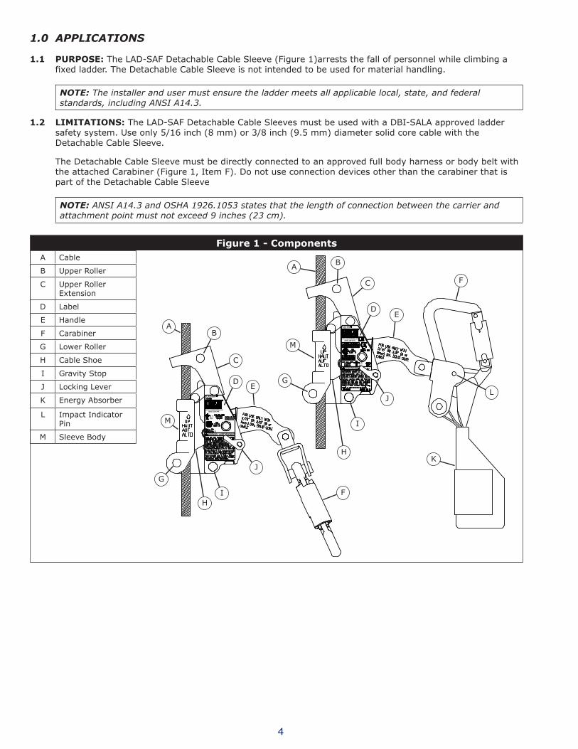
1.1 PURPOSe: the LAD-SAF Detachable cable Sleeve (Figure 1)arrests the fall of personnel while climbing a fixed ladder. The Detachable Cable Sleeve is not intended to be used for material handling.
NOTE: The installer and user must ensure the ladder meets all applicable local, state, and federal standards, including ANSI A14.3.
1.2 lIMITATIONS: the LAD-SAF Detachable cable Sleeves must be used with a DBi-SALA approved ladder safety system. Use only 5/16 inch (8 mm) or 3/8 inch (9.5 mm) diameter solid core cable with the Detachable cable Sleeve.
the Detachable cable Sleeve must be directly connected to an approved full body harness or body belt with the attached carabiner (Figure 1, item F). Do not use connection devices other than the carabiner that is part of the Detachable cable Sleeve
NOTE: ANSI A14.3 and OSHA 1926.1053 states that the length of connection between the carrier and attachment point must not exceed 9 inches (23 cm).
figure 1 - ComponentsA cable
B Upper Roller
c Upper Roller Extension
D Label
E Handle
F carabiner
G Lower Roller
H cable Shoe
i Gravity Stop
J Locking Lever
K Energy Absorber
L impact indicator Pin
M Sleeve Body
K
L
F
E
J
i
D
c
BA
M
G
H
AB
c
DE
F
J
iH
G
M

5
2.0 SYSTEM REQUIREMENTS
2.1 COMPATIBIlITY Of COMPONeNTS AND SUBSYSTeMS: this equipment is designed for use with DBi-SALA approved components and subsystems. the use of non-approved components and subsystems may jeopardize compatibility of equipment and could affect the safety and reliability of the complete system. contact DBi-SALA if you have questions about compatibility of equipment.
3.0 OPERATION AND USE
3.1 CONNeCTING THe DeTACHABle CABle Sleeve TO THe CARRIeR CABle: See Figure 1 for identification of components referenced in the following steps:
WARNING: In situations where a fall hazard exists, use a back-up fall arrest system, such as a lanyard, to protect against a fall.
Step 1. Ensure the sleeve is correctly positioned relative to the carrier cable (Figure 2). the “up” arrow on the sleeve must be pointing to the ascending direction. the detachable safety sleeve includes a gravity stop (1i) to reduce the possibility of installing the sleeve upside-down.
Step 2. Rotate the locking lever (1J) and pivot handle (1E) to its full upright position (Figure 2). this will draw back the cable shoe (1H) to allow insertion of the carrier cable (1A) into the sleeve housing (1M). the locking lever is on both sides of the Detachable cable Sleeve for right or left hand operation.
Step 3. Hold the sleeve upright and place the upper roller (1B) onto the cable. See Figure 3.
Step 4. Push back the upper roller extension (1c) and insert the cable through the slot on the side of the sleeve. Position the cable in the sleeve recess. Release the handle (1E) to lock the sleeve on the cable (see Figure 4). Ensure the locking lever (1J) is in the locked position before use . Figure 1 shows the locking lever in the locked position.
3.2 CONNeCTING THe DeTACHABle CABle Sleeve TO THe HARNeSS OR BODY BelT: connect the carabiner on the sleeve to the full body harness attachment point designated for ladder climbing. Always use the carabiner supplied on the sleeve. Do not substitute with other connectors. Do not use other connecting devices such as a short lanyard, chain, link, or clevis. connection between the sleeve and full body harness or body belt may be done before or after the sleeve has been installed onto the carrier cable. When connecting, ensure the carabiner gate is fully closed and locked.
ASCeNDING: to ascend the ladder climb up normally. the Detachable cable Sleeve will follow the climber. the cable is snapped out of the cable guides as they are encountered. Reconnect cable into cable guides after passing each cable guide. Do not remove the climbing sleeve from the cable to pass the cable guides.
DeSCeNDING: to descend the ladder, climb down smoothly in a normal position. Allow the sleeve to “lead” the climber down. climbing down out of position (leaning back excessively) will cause the sleeve to lock on the cable. if the sleeve locks, move upward slightly to release the sleeve and continue to descend the ladder. When climbing is completed remove the sleeve from the cable by rotating the locking lever and pivoting handle to its full upright position. the sleeve can now be removed from cable and properly stored.
figure 2
figure 3
figure 4

6
Ensure all hazards are addressed to provide climber safety. Hazardous environments or conditions include, but are not limited to; power lines, heat or flame, explosive gases, physical obstructions, and climbers ability and health. if a fall occurs the employer must have a rescue plan and the ability to implement it. After a fall the Detachable cable Sleeve must be inspected by a competent person other than the user. See section 5.0 of this manual for inspection steps.
4.0 TRAINING
4.1 TRAINING: it is the responsibility of the user and purchaser of this equipment to assure they are familiar with these instructions, operating characteristics, application limits, and the consequences of improper use of this equipment. Users and purchasers of this equipment must be trained in the correct care and use of this equipment.
IMPORTANT: Training must be conducted without exposing the user to a fall hazard. Training should be repeated on a periodic basis.
Step 1. Don a full body harness or body belt and attach to Detachable cable Sleeve.
Step 2. Ascend the ladder to approximately three feet. With both hands and feet on the climbing structure flex knees in a quick sitting motion to simulate a fall. This will activate the sleeve.
Step 3. Repeat Step 2. After the sleeve locks, move upward to unlock the sleeve.
Step 4. Descend the ladder and detach from the sleeve.
5.0 INSPECTION
5.1 fReQUeNCY:
•BeforeEachUseinspect the Detachable cable Sleeve according to sections 5.2 and 5.3.
•FormalInspection:A formal inspection of the Detachable cable Sleeve must be performed at least annually by a competent person other than the user. the frequency of formal inspections should be based on conditions of use or exposure. See sections 5.2 and 5.3. Record the inspection results in the inspection and maintenance log in Section 9.
•AfteraFall a formal inspection of the Detachable cable Sleeve must be performed by a competent person other than the user. Record the inspection results in the inspection and maintenance log in Section 9.
5.2 INSPeCTION GUIDelINeS: See Figure 1 for identification of the components described in the following guidelines:
inspect the handle (1E) and cable shoe (1H) for bends, cracks, and deformities. All fasteners must be 1. securely attached. operation of handle and cable shoe must be free and smooth. Springs must be secure and of sufficient strength to pull handle down.
inspect the locking lever (1J) for smooth operation, ensuring it springs back into its locked position when 2. released.
inspect the sleeve body (1M) for wear on the inside where the cable passes through.3.
inspect the impact indicator pin (1L). if the indicator pin is missing or damaged, the sleeve should not be 4. used until the pin is replaced.
inspect the energy absorber(1K) to determine it has not been activated. the energy absorber cover 5. should be secure and free of tears or damage.
5.3 if inspection reveals an unsafe or defective condition remove the Detachable cable Sleeve from service and destroy or contact an authorized service center for repair. Record the results in the inspection and Maintenance Log in Section 9 of this manual or use the i-Safe™ inspection web portal to maintain your inspection records (see Section 6).
7
6.0 I-SAFE™ RFID
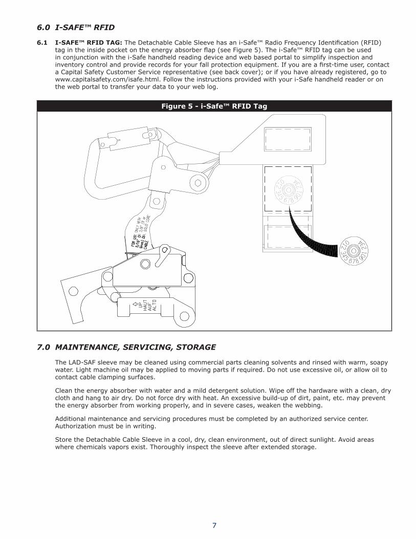
6.1 I-SAfe™ RfID TAG: The Detachable Cable Sleeve has an i-Safe™ Radio Frequency Identification (RFID) tag in the inside pocket on the energy absorber flap (see Figure 5). The i-Safe™ RFID tag can be used in conjunction with the i-Safe handheld reading device and web based portal to simplify inspection and inventory control and provide records for your fall protection equipment. If you are a first-time user, contact a capital Safety customer Service representative (see back cover); or if you have already registered, go to www.capitalsafety.com/isafe.html. Follow the instructions provided with your i-Safe handheld reader or on the web portal to transfer your data to your web log.
Figure5-i-Safe™RFIDTag
7.0 MAINTENANCE, SERVICING, STORAGE
the LAD-SAF sleeve may be cleaned using commercial parts cleaning solvents and rinsed with warm, soapy water. Light machine oil may be applied to moving parts if required. Do not use excessive oil, or allow oil to contact cable clamping surfaces.
clean the energy absorber with water and a mild detergent solution. Wipe off the hardware with a clean, dry cloth and hang to air dry. Do not force dry with heat. An excessive build-up of dirt, paint, etc. may prevent the energy absorber from working properly, and in severe cases, weaken the webbing.
Additional maintenance and servicing procedures must be completed by an authorized service center. Authorization must be in writing.
Store the Detachable cable Sleeve in a cool, dry, clean environment, out of direct sunlight. Avoid areas where chemicals vapors exist. thoroughly inspect the sleeve after extended storage.

8
8.0 LAbELING
8.1 Labels must be securely attached and fully legible:
1
2
3
Part number1. Serial number2. WARninG: Read and follow manufacturer’s instructions supplied 3. with this product before use. Do not use with incompatible cables. Use only with DBi-SALA approved system and harness. Maximum distance allowed between system cable and harness attachment point is 9 inches. inspect before each use. Make only compatible connections between sleeve and harness. Failure to heed warnings may result in serious injury or death.
1
2
3
Part number1. Date Manufactured (Year/Month)2. WARninG: Read and follow manufacturer’s instructions supplied 3. with this product before use. Do not use with incompatible cables. Use only with DBi-SALA approved system and harness. Maximum distance allowed between system cable and harness attachment point is 9 inches. inspect before each use. Make only compatible connections between sleeve and harness. Failure to heed warnings may result in serious injury or death.
1 2
2
Maximum distance allowed between system cable and harness 1. attachment point is 9 inches (23 cm).Do not use with Lanyard.2.

9
9.0 INSPECTION AND MAINTENANCE LOG
SeRIAl NUMBeR:
MODel NUMBeR:
DATe PURCHASeD: DATe Of fIRST USe:
INSPeCTION DATe INSPeCTION ITeMS NOTeD
CORReCTIve ACTION MAINTeNANCe PeRfORMeD
Approved By:
Approved By:
Approved By:
Approved By:
Approved By:
Approved By:
Approved By:
Approved By:
Approved By:
Approved By:
Approved By:
Approved By:
Approved By:
Approved By:
Approved By:
Approved By:
Approved By:
Approved By:

10
9.0 INSPECTION AND MAINTENANCE LOG
SeRIAl NUMBeR:
MODel NUMBeR:
DATe PURCHASeD: DATe Of fIRST USe:
INSPeCTION DATe INSPeCTION ITeMS NOTeD
CORReCTIve ACTION MAINTeNANCe PeRfORMeD
Approved By:
Approved By:
Approved By:
Approved By:
Approved By:
Approved By:
Approved By:
Approved By:
Approved By:
Approved By:
Approved By:
Approved By:
Approved By:
Approved By:
Approved By:
Approved By:
Approved By:
Approved By:


A capital Safety company
CSG USA3833 Sala WayRed Wing, Mn 55066-5005toll Free: 800.328.6146Phone: 651.388.8282Fax: [email protected]
CSG Canada ltd.60 Export BoulevardMississauga, ontario L5S 1Y9canadatoll Free: 800.387.7484Phone: 905.795.9333Fax: [email protected]
CSG Northern europe ltd.7 Christleton Court • Stuart Rd.Manor Park • RuncornCheshire WA7 1ST • UKPhone: +44 (0) 1928 571324Fax: +44 (0) 1928 [email protected]
CSG eMeA (france)Le Broc center Z.i. 1ère Avenue-5600 MBP 15 • 06511 Carros CedexPhone: +33 (0)4 97 10 00 10Fax: +33 (0)4 93 08 79 [email protected]
CSG Asia Pte ltd.no. 6, tuas Avenue 18Singapore 638892Phone: +65 6558 7758Fax: +65 6558 [email protected]
CSG (Aust) Pty ltd.20 Fariola Street • SliverwaterSydney, nSW 2128AustraliaPhone: +61 (2) 9748 0335Fax: +61 (2) 9748 [email protected]
www.capitalsafety.com