DESULPHURIZATION
43
Desulfurization
-
Upload
nithinkallayil -
Category
Documents
-
view
2 -
download
0
description
fs
Transcript of DESULPHURIZATION

DesulfurizationDesulfurization

1. Hydrotreater
2. Mercaptane Oxidizer (Merox)
Desulphurization Units
3. Atmospheric Residue Desulphuriser (ARDS)
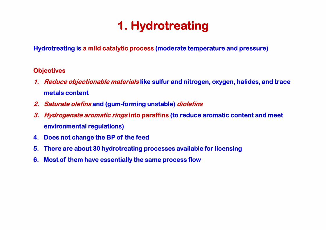
Hydrotreating is a mild catalytic process (moderate temperature and pressure)
Objectives
1. Reduce objectionable materials like sulfur and nitrogen, oxygen, halides, and trace
metals content
2. Saturate olefins and (gum-forming unstable) diolefins
3. Hydrogenate aromatic rings into paraffins (to reduce aromatic content and meet
1. Hydrotreating
3. Hydrogenate aromatic rings into paraffins (to reduce aromatic content and meet
environmental regulations)
4. Does not change the BP of the feed
5. There are about 30 hydrotreating processes available for licensing
6. Most of them have essentially the same process flow

Feeds and Products
The feed ranges from Naphtha to reduced crude (residue).
The heavier the feed the more severe the process is (higher T & P)
Feed and Products
Process – Hydrotreating
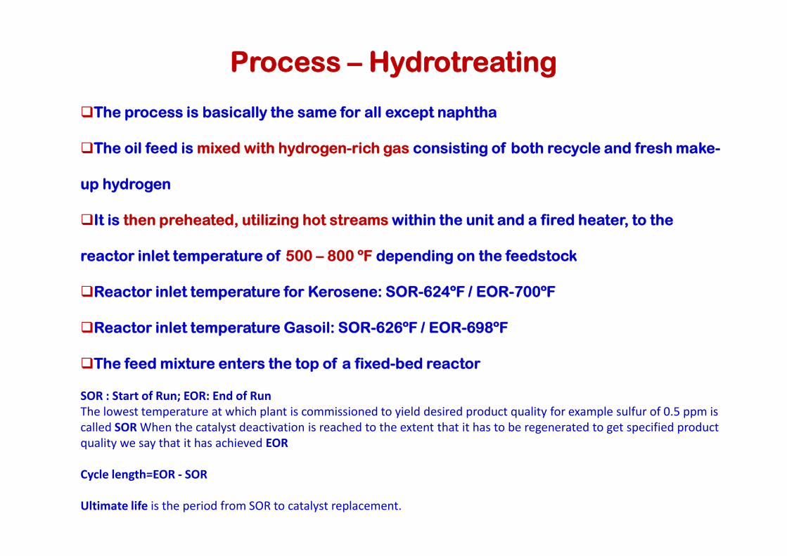
The process is basically the same for all except naphtha
The oil feed is mixed with hydrogen-rich gas consisting of both recycle and fresh make-
up hydrogen
It is then preheated, utilizing hot streams within the unit and a fired heater, to the
reactor inlet temperature of 500 – 800 ºF depending on the feedstock
Reactor inlet temperature for Kerosene: SOR-624ºF / EOR-700ºF
Reactor inlet temperature Gasoil: SOR-626ºF / EOR-698ºF
The feed mixture enters the top of a fixed-bed reactor
SOR : Start of Run; EOR: End of RunThe lowest temperature at which plant is commissioned to yield desired product quality for example sulfur of 0.5 ppm is called SOR When the catalyst deactivation is reached to the extent that it has to be regenerated to get specified product quality we say that it has achieved EOR
Cycle length=EOR - SOR
Ultimate life is the period from SOR to catalyst replacement.

In the presence of the metal-oxide catalyst, the hydrogen reacts with the objectionable materials in the oil to produce hydrogen sulfide (H2S), ammonia (NH3), saturated hydrocarbons, and free metals
Metals remain on the surface of the catalyst and other products leave the reactor with the oil-hydrogen stream
reactor outlet cooled (by heating the feed) before separating the oil from the H2-rich gas
H2-rich gas is recycled and supplemented with fresh make-up H2 before it is mixed with the fresh feed again
Process – Hydrotreating Contd...
Some gas is purged continuously from recycle gas section to H2 recovery unit maintain the required hydrogen purity and partial pressure in the reactor
Desulfurized oil is stripped of any remaining hydrogen sulfide (and light ends to adjust the flash point) in a steam stripper
Small quantity of wild naphtha is produced from the top of the stripper and is sent to the Naphtha HTU (via CDU fractionator or ARDS stabilizer) for recovery as product
The stripped oil is fed to a vacuum dryer (operating at 80 mmHg, using a two-stage steam jet ejector system) where moisture is removed
The treated final product from the dryer bottom is cooled then sent to storage
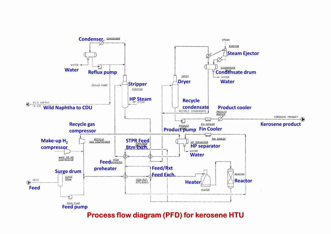
Process – Kerosene Hydrotreating
Product is Aviation Turbine Kerosene (ATK) or illuminating Kerosene (IK)
The major improvements for the product quality will be with respect to smoke point (23 to 25) sulfur and olefin to (0.05 wt% max)
The reaction pressure is 668 psig & H2 consumption 235 SCF/B feed
The hydrogen requirements of the reaction are jointly met by ARDS purge gas and high purity hydrogen make up gas
A two-bed reactor with quench gas is provided

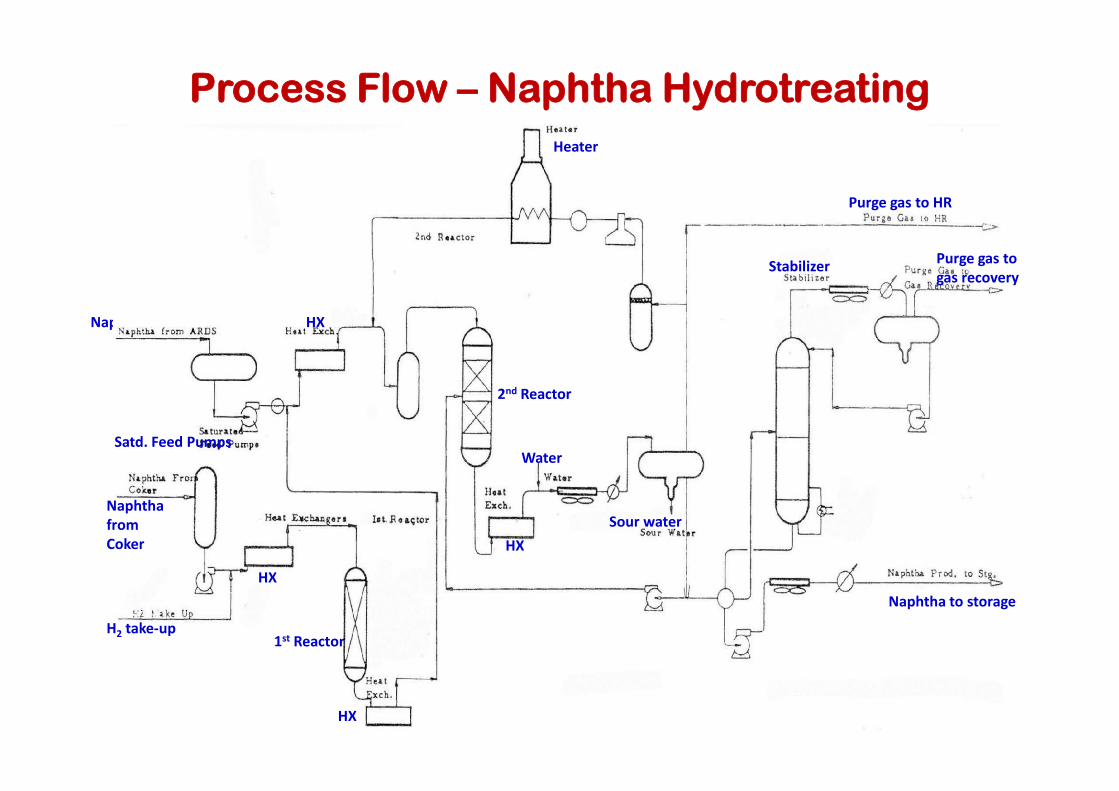
Process – Naphtha Hydrotreating
Naphtha Hydrotreater -designed to meet the requirements for blending into Petrochemical Naphtha pool or into Motor Gasoline pool
Major improvements for the product quality will be in the olefins content, nitrogen content & sulfur content
Reaction pressure is 415 psig
Hydrogen consumption is about 415 SCF/BBL
The Coker Naphtha is first mixed with make-up H2 gas, heated up and sent to the first The Coker Naphtha is first mixed with make-up H2 gas, heated up and sent to the first reactor where a liquid phase hydrogenation reaction is carried out to take care of the diolefins and gums in Coker naphtha (which would otherwise cause severe fouling problems in vapor phase naphtha hydrotreating reaction)
The feed (saturated naphtha) from ARDS (after heating up against 2nd reactor effluent) is then combined with first reactor effluent and recycle gas and vaporized totally in a heater before sending to the second reactor
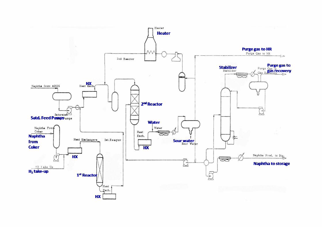

Hydrotreating reactions are completed in the second reactor which has 2 types of catalysts
Distillation section consist of a naphtha stabilizer to achieve required RVP & H2S content on finished product
Reboiler heat comes from second reactor effluent
Process – Naphtha Hydrotreating contd...
Process – Diesel Hydrotreating
Major improvements for the product quality are with respect to sulfur content and reduction of Conradson carbon (from 0.22 % to 0.05 wt%)
The reaction pressure is 668 psig and H2 consumption about 277 SCF/B feed
The hydrogen requirements of the reaction are jointly met by ARDS purge gas and high purity hydrogen make up gas
A two bed reactor with quench gas is provided
The diesel product is cooled and sent through a coalescer to storage.

Hydrotreating catalysts: Cobalt and molybdenum oxides on silica alumina base (CoMo)Nickel oxideNickel thiomolybdateTungsten and nickel sulfidesVanadium oxide
Desulfurization CoMo catalysts are more common because: High selectivityEasy to regenerate
Hydrotreating Catalyst
Easy to regenerateResistant to poisons
Denitrification (denitrification) requires the more efficient Nickel-molybdenum (NiMo) catalyst on silica alumina base.For middle distillates, 10% nickel-tungsten catalyst is added to NiMo catalyst to treat high nitrogen concentration
Both CoMo and NiMo catalysts can remove sulfur and nitrogen. However, CoMo is more selective for sulfur removal and NiMo is more selective to nitrogen removal

Usually both desulfurization and denitrification are necessary and a nickel-cobaltmolybdenum (NiCoMo) catalyst over silica alumina base is used
Since nitrogen is more difficult to remove than sulfur from HC, any treatment which reduces excess nitrogen to a satisfactory level also removes excess sulfur
NiMo catalyst has a higher hydrogenation activity than CoMo catalyst (at the same T&P) which results in a greater saturation of aromatic rings
Hydrotreating gasoil (400-1050 ºF) requires larger pore-size catalyst (than naphtha for
Hydrotreating Catalyst contd...
Hydrotreating gasoil (400-1050 ºF) requires larger pore-size catalyst (than naphtha for example) to overcome diffusion restrictions at both SOR and EOR conditions
Pores that are larger than necessary are not desirable because it decreases the catalyst surface area
Pores that are smaller than necessary are not desirable because of diffusion restrictions
Highest activity is maintained if pore volume is concentrated in a very narrow range of pore diameters
Catalyst consumption varies from 1 to 7 PTB of feed depending on operation severity (T&P) and feed (API & S, N, halides, and metal content).

Hydrotreating Catalyst contd...
Hydrotreating catalyst requires activation by converting the hydrogenation metals from the oxide form to the sulfide form every time a new catalyst is added or unit is shut down for maintenance (catalyst is exposed to air)
Nickel containing catalysts require activation by presulfiding with carbon disulfide, mercaptans, or dimethyl sulfide before bringing up to reaction temperature
Some refineries activate cobalt-moly catalysts by injecting the sulfiding chemical into the oil feed during startup
If the feed is high in sulfur then the feed is enough for the sulfiding operation
Catalyst Activation
If the feed is high in sulfur then the feed is enough for the sulfiding operation
The sulfiding reaction is highly exothermic and care must be taken to prevent excessive reactor temperature during activation

1)
Reactions

Reactions contd...
Smaller compounds are desulfurized more easily than larger ones
Difficulty of sulfur removal increases in the order; paraffins, naphthenes, then aromatics
Nitrogen removal requires more severe conditions (T&P) than sulfur removal
Hydrogen consumption;
Desulfurization → 70 scf/bbl feed (per % S removed)
Reactions contd...
Desulfurization → 70 scf/bbl feed (per % S removed)
Denitrification → 230 scf/bbl feed (per % N removed)
Deoxygenation → 180 scf/bbl feed (per % O removed)
Olefin/Aromatic saturation → use stoichiometry
Cracking → V. high H2 required (if operations are severe enough)

Increasing T and H2 partial pressure increases S and N removal, and hydrogen consumption
Excessive T increases coke formation (and should be avoided)
Increasing pressure increases hydrogen saturation and reduces coke formation
Process Variables
Liquid Hourly Space Velocity (LHSV) = Total volumetric flow rate to reactor / total catalyst volume
Unit : hr-1

2. Mercaptane Oxidation (Merox)
Two major types in many refineries
Merox Mercaptans Extraction Process (gases, C3, C4, LPG, Naphtha) Merox Sweetening Process (Kerosene/Jet Fuel)
The overall oxidation reaction that takes place in converting mercaptans to disulfides is:
4 R-SH + O2 → 2R-S-S-R + 2H2O(mercaptans) (disulfides)
The Merox catalyst is either a liquid or impregnated charcoal granules The Merox catalyst is either a liquid or impregnated charcoal granules
Merox Mercaptans Extraction process achieve the following objectives1. Improve the odor of the naphtha2. Reduce mercaptans sulfur (to pass doctor test*)
The units are based on UOP’s licensed conventional Fixed Bed Sweetening MEROX process
Merox process is usually more economical than using a catalytic hydrodesulfurization process
*A qualitative test for the presence of hydrogen sulfide or mercaptans in gasoline, jet fuel, kerosene and similar petroleum products.
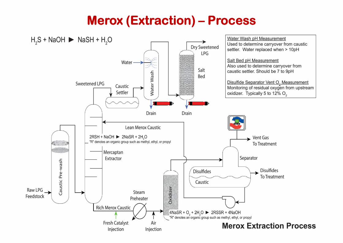
Merox (Extraction) – Process

Merox (Extraction) – Process
Merox unit –Simplified Process Flow

The unit treats light naphtha produced in the coker unit (along with some of the coker heavy naphtha)
The coker naphtha entering the unit passes through a guard caustic scrubber which insures complete removal of H2S (if present) from the naphtha
The naphtha is then mixed with a controlled quantity of air in a mixer before entering the Merox reactor
The merox reactor contains a bed of specially selected activated charcoal impregnated with merox catalyst and wetted with caustic solution
Merox (Extraction) – Process
While the naphtha air mixture passes through the reactor, the mercaptans in the naphtha are converted to disulfides
Caustic circulation pump provides intermittent circulation of caustic from the settler to wet the catalyst bed
The frequency of caustic circulation depends on the stock being treated and activity of the catalyst
The naphtha effluent from the reactor is sent to a caustic settler to separate the entrained caustic
The naphtha then passes through a sand filter (to reduce alkalinity and caustic haze) before sending to storage

Merox (Sweetening) - Process Flow

Merox (Sweetening) - Process Flow
Conventional Merox for sweetening jet fuel or kerosene Process

Feedstock jet fuel or kerosene is first prewashed in a batch caustic prewash vessel to remove any H2S that would interfere with the sweetening.
The following reaction takes place:H2S + NaOH → NaSH + H2O
The jet fuel or kerosene feedstock from the top of the caustic prewash vessel is injected with compressed air and enters the top of the Merox reactor vessel along with any injected caustic
The pressure maintained in the reactor is chosen so that the injected air will completely dissolve in the feedstock at the operating temperature
Merox (Sweetening) – Process
completely dissolve in the feedstock at the operating temperature
The Merox reactor is a vertical vessel containing a fixed bed of charcoal granules that have been impregnated with the UOP proprietary catalyst
The mercaptan oxidation reaction takes place in an alkaline environment provided by caustic being pumped into the reactor on an intermittent (as needed) basis
The oxidation reaction that takes place is:4 R-SH + O2 → 2R-S-S-R + 2H2O
Mercaptan oxidation reaction takes place as the feedstock percolates downward over the catalyst
Reactor effluent flows through a caustic settler vessel where it forms a bottom layer of aqueous caustic solution and an upper layer of water-insoluble sweetened product
Caustic solution remains in the caustic settler so that the vessel contains a reservoir for the supply of caustic that is intermittently pumped into the reactor to maintain the alkaline environment
Merox (Sweetening) – Process contd...
Sweetened product from the caustic settler vessel flows through a water wash vessel to remove any entrained caustic as well as any other unwanted water-soluble substances
Water-washed product flows through a salt bed vessel to remove any entrained water
The salt filtered product flows through a clay filter vessel to remove any oil-soluble substances, organometallic compounds (especially copper) and particulate matter, to meet jet fuel product specifications

3. ARDS

ARDS -Objectives
ARDS is a fixed bed catalytic process for hydrotreating a variety of feedstocks (heavy oils like atmospheric residue and some vacuum residues)
Objectives In the reaction section: To reduce the sulfur content of CDU atmospheric residue from 4.5 to 0.5-0.7 wt% and metal content from 88 to 21 ppmw in addition to nitrogen and residual carbon in the presence of hydrogen for meeting quality criteria of the feed/products to the downstream processing units
In the fractionation section: To obtain lighter (more valuable) products such as In the fractionation section: To obtain lighter (more valuable) products such as LPG and Naphtha, in addition to middle distillate and low-sulfur fuel oil which are excellent feedstocks for other process units like fluid catalytic crackers (FCC), hydrocrackers (HCR), and vacuum unit and delayed coker
Commercial Name → Unicracking/HDS Process
Licensor → Jointly licensed by Unocal* and UOP
*Unocal processes have been licensed for use in over 260 units in 35 countries worldwide
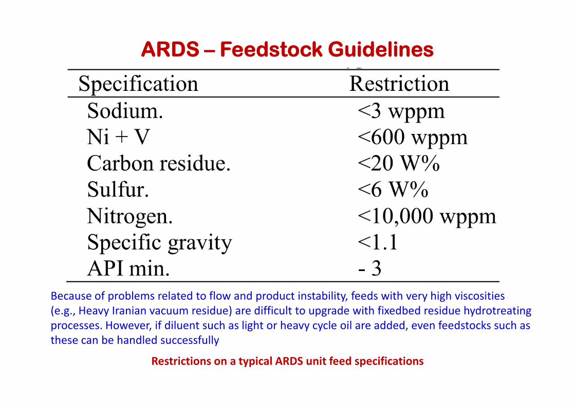
ARDS – Feedstock Guidelines
Restrictions on a typical ARDS unit feed specifications
Because of problems related to flow and product instability, feeds with very high viscosities (e.g., Heavy Iranian vacuum residue) are difficult to upgrade with fixedbed residue hydrotreatingprocesses. However, if diluent such as light or heavy cycle oil are added, even feedstocks such as these can be handled successfully
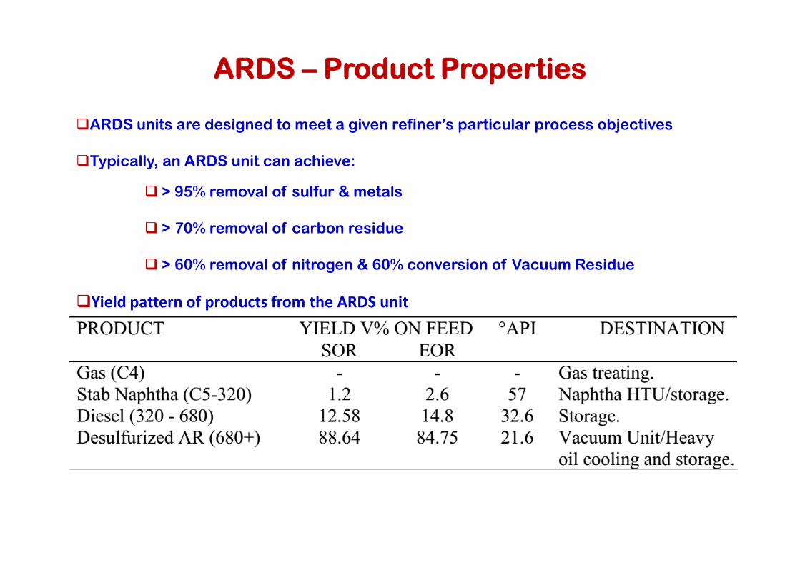
ARDS units are designed to meet a given refiner’s particular process objectives
Typically, an ARDS unit can achieve:
> 95% removal of sulfur & metals
> 70% removal of carbon residue
> 60% removal of nitrogen & 60% conversion of Vacuum Residue
ARDS – Product Properties
Yield pattern of products from the ARDS unit

ARDS – Process Flow
ARDS – Process
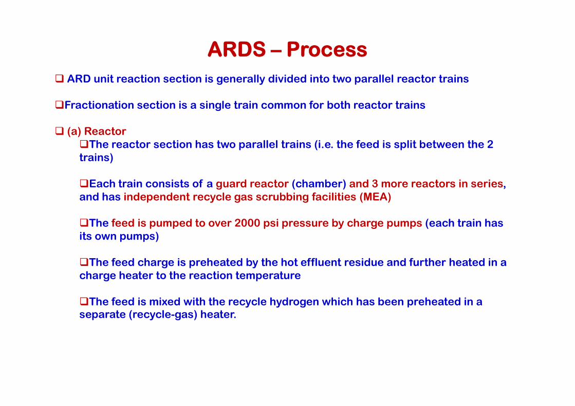
ARD unit reaction section is generally divided into two parallel reactor trains
Fractionation section is a single train common for both reactor trains
(a) ReactorThe reactor section has two parallel trains (i.e. the feed is split between the 2 trains)
Each train consists of a guard reactor (chamber) and 3 more reactors in series, and has independent recycle gas scrubbing facilities (MEA)
The feed is pumped to over 2000 psi pressure by charge pumps (each train has its own pumps)
The feed charge is preheated by the hot effluent residue and further heated in a charge heater to the reaction temperature
The feed is mixed with the recycle hydrogen which has been preheated in a separate (recycle-gas) heater.

The feed enters a guard chamber (a small reactor that contains a relatively small quantity of ARDS catalyst) to remove particulate matter and residual salt from the feed to protect the other three following reactors
The catalyst in the reactors is chosen such that demetallization is achieved in the first two reactors and the desulfurization is achieved in the third and fourth reactors
A substantial fraction of the VR feed (1050+ ºF material) is converted into gas oil
The hydrogen consumption is about 610 - 670 scf/bbl of feed
ARDS – Process contd...
The hydrogen consumption is about 610 - 670 scf/bbl of feedThe reactor effluent (two phase) is separated to liquid and vapor in a HPHS (High Pressure Hot Separator) The pressure is 1740 psig at SOR and 1720 psig at EOR
The vapor is cooled to 500 ºF and sent to HPWS (High Pressure Warm Separator) where the high MW HCs (which condensate because of cooling) are removed because they might cause emulsions in the HPCS (High Pressure Cold Separator) where water will be condensed
The liquid from HPWS is mixed with the liquid from the HPHS and sent to LPHS (low pressure hot separator)
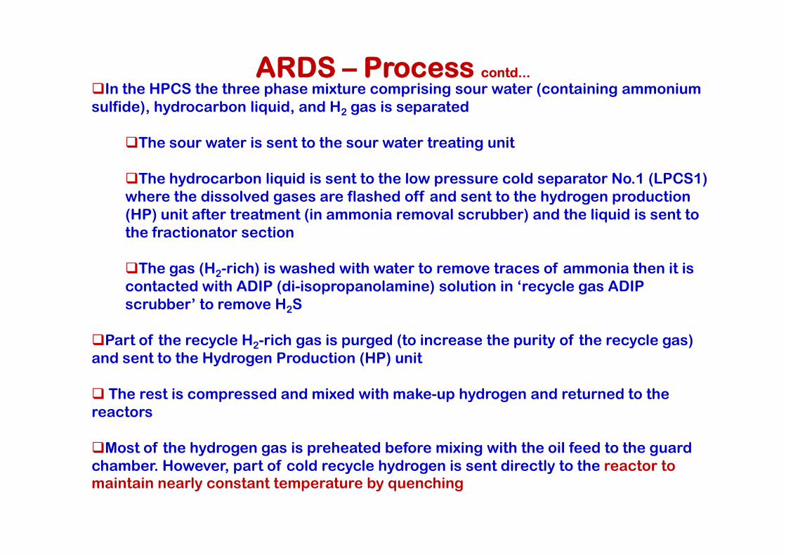
In the HPCS the three phase mixture comprising sour water (containing ammonium sulfide), hydrocarbon liquid, and H2 gas is separated
The sour water is sent to the sour water treating unit
The hydrocarbon liquid is sent to the low pressure cold separator No.1 (LPCS1) where the dissolved gases are flashed off and sent to the hydrogen production (HP) unit after treatment (in ammonia removal scrubber) and the liquid is sent to the fractionator section
The gas (H2-rich) is washed with water to remove traces of ammonia then it is contacted with ADIP (di-isopropanolamine) solution in ‘recycle gas ADIP
ARDS – Process contd...
2
contacted with ADIP (di-isopropanolamine) solution in ‘recycle gas ADIP scrubber’ to remove H2S
Part of the recycle H2-rich gas is purged (to increase the purity of the recycle gas) and sent to the Hydrogen Production (HP) unit
The rest is compressed and mixed with make-up hydrogen and returned to the reactors
Most of the hydrogen gas is preheated before mixing with the oil feed to the guard chamber. However, part of cold recycle hydrogen is sent directly to the reactor to maintain nearly constant temperature by quenching

ARDS – Process contd...
(b) Fractionator Section:
Dissolved vapors released in the LPHS are cooled then separated in the LPCS2 into gas, HC liquid, and water
HC liquid is fed separately to the fractionator Gas (rich in H2) is sent after ammonia removal to either HP or H2S Removal (HSR) unit Water is sent to SWT unit
Liquids from the LPHS of both trains are sent to the flash zone of the fractionator after preheat in the main heaterafter preheat in the main heater
The fractionator is similar to a conventional crude unit distillation column
Naphtha produced from the fractionator overhead is sent to a debutanizer to control its IBP, flash point, and RVP by removing C4 and lighter gases. Both debutanizer top (LPG) and bottom (naphtha) products are sent to storage
Distillate is drawn as a side stream from the fractionator to a steam side stripper to adjust its IBP then sent to storage
The fuel oil (fractionator bottoms) is sent to storage after cooling

(C) Catalyst
There are catalysts for demetallization, desulfurization, denitrification, and conversion of residual oils
A client’s objectives determine which combination of catalysts is best for a particular plant
To convert a high-metals residue into low-sulfur fuel oil, a bed of demetallizationcatalyst might be used followed by a bed of desulfurization catalyst
ARDS – Process contd...
To achieve substantial conversion and denitrification, the above catalysts might be followed by a hydrotreating or mild hydrocracking catalyst
Desulfurization catalyst life cycle ranges from one to two years
Demetallization catalysts must be reclaimed or disposed of once or twice per year
Desulfurization catalyst can be regenerated if protected by a demetallizationcatalyst

Queries?

Merox (Extraction) - Process Flow
Merox for Coker Naphtha treatment
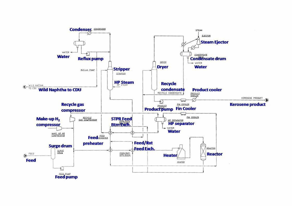
Wild Naphtha to CDU
Water
Condenser
Reflux pump
Stripper
HP Steam
Dryer
Recycle condensate
Water
Product cooler
Condensate drum
Steam Ejector
Process flow diagram (PFD) for kerosene HTU
Make-up H2
compressor
Recycle gas compressor
Feed
Surge drum
Feed pump
Feed preheater
STPR Feed Btm Exch.
Feed/RxtFeed Exch.
ReactorHeater
Water
HP separator
Fin CoolerProduct pumpKerosene product
Naphtha from ARDS HX
2nd Reactor
Heater
Purge gas to HR
Purge gas to gas recovery
Stabilizer
Process Flow – Naphtha Hydrotreating
Satd. Feed Pumps
Naphtha from Coker
H2 take-up
HX
HX
HX
1st Reactor
2nd Reactor
Water
Sour water
Naphtha to storage
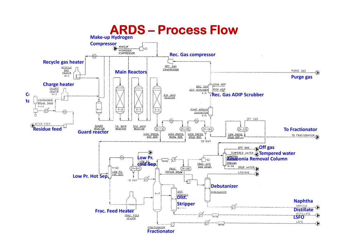
ARDS – Process Flow
Condensate tank
Charge heater
Recycle gas heater
Make-up Hydrogen Compressor
Rec. Gas compressor
Main ReactorsPurge gas
Rec. Gas ADIP Scrubber
Residue feedGuard reactor To Fractionator
Naphtha
Distillate
LSFO
Fractionator
Debutanizer
Dist. Stripper
Frac. Feed Heater
Low Pr. Hot Sep.
Low Pr. cold Sep.
Ammonia Removal Column
Off gasTempered water