DESIGNING, PROTOTYPING AND INVESTIGATION OF …
131
University of Windsor University of Windsor Scholarship at UWindsor Scholarship at UWindsor Electronic Theses and Dissertations Theses, Dissertations, and Major Papers 11-6-2015 DESIGNING, PROTOTYPING AND INVESTIGATION OF ADVANCED DESIGNING, PROTOTYPING AND INVESTIGATION OF ADVANCED FIVE-PHASE AXIAL FLUX SRM FOR ELECTRIFIED VEHICLE FIVE-PHASE AXIAL FLUX SRM FOR ELECTRIFIED VEHICLE APPLICATION APPLICATION Anas Labak University of Windsor Follow this and additional works at: https://scholar.uwindsor.ca/etd Recommended Citation Recommended Citation Labak, Anas, "DESIGNING, PROTOTYPING AND INVESTIGATION OF ADVANCED FIVE-PHASE AXIAL FLUX SRM FOR ELECTRIFIED VEHICLE APPLICATION" (2015). Electronic Theses and Dissertations. 5524. https://scholar.uwindsor.ca/etd/5524 This online database contains the full-text of PhD dissertations and Masters’ theses of University of Windsor students from 1954 forward. These documents are made available for personal study and research purposes only, in accordance with the Canadian Copyright Act and the Creative Commons license—CC BY-NC-ND (Attribution, Non-Commercial, No Derivative Works). Under this license, works must always be attributed to the copyright holder (original author), cannot be used for any commercial purposes, and may not be altered. Any other use would require the permission of the copyright holder. Students may inquire about withdrawing their dissertation and/or thesis from this database. For additional inquiries, please contact the repository administrator via email ([email protected]) or by telephone at 519-253-3000ext. 3208.
Transcript of DESIGNING, PROTOTYPING AND INVESTIGATION OF …

University of Windsor University of Windsor
Scholarship at UWindsor Scholarship at UWindsor
Electronic Theses and Dissertations Theses, Dissertations, and Major Papers
11-6-2015
DESIGNING, PROTOTYPING AND INVESTIGATION OF ADVANCED DESIGNING, PROTOTYPING AND INVESTIGATION OF ADVANCED
FIVE-PHASE AXIAL FLUX SRM FOR ELECTRIFIED VEHICLE FIVE-PHASE AXIAL FLUX SRM FOR ELECTRIFIED VEHICLE
APPLICATION APPLICATION
Anas Labak University of Windsor
Follow this and additional works at: https://scholar.uwindsor.ca/etd
Recommended Citation Recommended Citation Labak, Anas, "DESIGNING, PROTOTYPING AND INVESTIGATION OF ADVANCED FIVE-PHASE AXIAL FLUX SRM FOR ELECTRIFIED VEHICLE APPLICATION" (2015). Electronic Theses and Dissertations. 5524. https://scholar.uwindsor.ca/etd/5524
This online database contains the full-text of PhD dissertations and Masters’ theses of University of Windsor students from 1954 forward. These documents are made available for personal study and research purposes only, in accordance with the Canadian Copyright Act and the Creative Commons license—CC BY-NC-ND (Attribution, Non-Commercial, No Derivative Works). Under this license, works must always be attributed to the copyright holder (original author), cannot be used for any commercial purposes, and may not be altered. Any other use would require the permission of the copyright holder. Students may inquire about withdrawing their dissertation and/or thesis from this database. For additional inquiries, please contact the repository administrator via email ([email protected]) or by telephone at 519-253-3000ext. 3208.

DESIGNING, PROTOTYPING AND INVESTIGATION
OF ADVANCED FIVE-PHASE AXIAL FLUX SRM
FOR ELECTRIFIED VEHICLE APPLICATION
By
Anas Labak
A Dissertation
Submitted to the Faculty of Graduate Studies
Through the Department of Electrical and Computer Engineering
in Partial Fulfillment of the Requirements for the
Degree of Doctor of Philosophy
at the University of Windsor
Windsor, Ontario, Canada
© 2015 Anas Labak
DESIGNING, PROTOTYPING AND INVESTIGATION OF
ADVANCED FIVE-PHASE AXIAL FLUX SRM FOR
ELECTRIFIED VEHICLE APPLICATION
By
Anas Labak
APPROVED BY:
_______________________________________________________ Tomy Sebastian, External Examiner
Director, Motor Drive Systems at Halla Mechatronics
_______________________________________________________ Nader Zamani
Department of Mechanical, Automotive & Materials Engineering
_______________________________________________________ Mohammed A. S. Khalid
Department of Electrical and Computer Engineering
_______________________________________________________ Kemal Tepe
Department of Electrical and Computer Engineering
_______________________________________________________ Narayan C. Kar, Advisor
Department of Electrical and Computer Engineering
19 June 2015

iii
AUTHOR’S DECLARATION OF ORIGINALITY
I hereby certify that I am the sole author of this dissertation and that parts of this
dissertation have been published or submitted for publication. I also certify that I have the
right to use all or part of the published work in other work.
I certify that, to the best of my knowledge, my dissertation does not infringe upon
anyone’s copyright nor violate any proprietary rights and that any ideas, techniques,
quotations, or any other material from the work of other people included in my
dissertation, published or otherwise, are fully acknowledged in accordance with the
standard referencing practices.
I declare that this is a true copy of my dissertation, including any final revisions,
as approved by my thesis committee and the Graduate Studies office, and that this
dissertation has not been submitted for a higher degree to any other University or
Institution.

iv
ABSTRACT
The recent interest by the automotive industry in finding an electric motor that has
high power density, rugged construction with high temperature adaptability, and fault
tolerance ability has revived the research on switched reluctance motors (SRMs). Due to
the aforementioned characteristics, SRM is considered an attractive alternative to
traditional electric motors in electric vehicle (EV) applications. However, there are
challenges such as torque ripple and acoustic noise that need to be addressed. The aim of
this dissertation is to provide solutions through fundamental design improvements in
order to develop a viable SRM-based propulsion system.
In order to analyze and quantify the major well-known issues of SRM, firstly, a case
study based on finite element analysis (FEA) is performed on two types of SRM designs,
a conventional SRM and a new design of in-wheel outer-rotor SRM. Despite the
improvement in torque ripple provided by the new design, a comparative performance
analysis suggests that further design modification is necessary in order to mitigate the
acoustic noise and vibration issue in the machine while maintaining the achieved
improvements. Consequently, an axial-flux configuration of SRM is proposed and its
design and analysis is presented. Detailed procedure of deriving the output power
equation as a function of motor dimensions and parameters are provided. A novel
modified phase winding design method is thoroughly explained, and the inductance
determination by different methods is verified experimentally. A 3-D FEA unveils
excessive end core and radial flux fringing effects, subsequently, an exclusive pole-shape
design is proposed. The dynamic operation of the motor is analyzed through 3-D FEA
motion model. The prototype development process and static testing are demonstrated.

v
Experimental investigations have revealed issue of low inductance ratio due to higher
leakage flux in this type of machine. Subsequently, three different novel approaches
based on segmented grain-oriented steel core and magnetic shielding are proposed to
mitigate the leakage flux, and then tested individually using 3-D FEA. In addition,
comparative performance analysis of the original machine model and the machine with
each of these approaches is carried out and improvement in the inductance ratio is
observed. Overall, the proposed ASRM, with all aforementioned design improvements is
found to satisfactorily address the major challenges.

vi
DEDICATION
To My Family

vii
ACKNOWLEDGEMENT
I am thankful to God Almighty for giving me the opportunity to pursue the
doctoral program and the strength and patience to successfully complete it. I am grateful
to my wonderful parents whose love, encouragement and sacrifice has made me what I
am today. My heartfelt thanks go to my wife, Aya, and to my adorable children,
Tasneem, Mohammad, and Malik for tolerating me and contributing toward my doctoral
degree in all ways possible.
I wish to express my sincere gratitude to my advisor Dr. Narayan Kar for his
assistance at every step of the way. His guidance has had an immense influence on my
professional growth and without his technical expertise, reviews, and criticism it would
not have been possible to shape this dissertation. I would also like to thank my internal
committee members, Dr. Nader Zamani, Dr. Mohammed Khalid, and Dr. Kemal Tepe for
their valuable suggestions and guidance in the completion of this work. My sincere
thanks to Dr. Tomy Sebastian for reviewing my dissertation and providing fruitful
comments that kindled my brain.
In the end, I want to thank my fellow graduate students in the Centre for Hybrid
Research and Green Energy (CHARGE) for their support and encouragement. Working
in their friendly company was a memorable experience.
viii
TABLE OF CONTENTS
Author’s Declaration of Originality ................................................................................... iii
ABSTRACT ....................................................................................................................... iv
DEDICATION ................................................................................................................... vi
ACKNOWLEDGEMENT ................................................................................................ vii
NOMENCLATURE ....................................................................................................... xvii
1. Introduction .................................................................................................................... 1
1.1 Overview .............................................................................................................. 1
1.2 Background Literature on EV Motor Technology ............................................... 2
1.3 SRM Research Background ................................................................................. 6
1.4 Research Objective .............................................................................................. 8
1.5 Research Contributions ........................................................................................ 9
1.6 Dissertation Outline ............................................................................................. 9
2. Design and Investigation of Radial FLUX SWITCHED reluctance Machines ........... 12
2.1 Chapter Objectives: ............................................................................................ 12
2.2 Introduction and Operating Principle of SRM: .................................................. 12
2.3 SRM Classification and Configuration .............................................................. 13
2.4 Case study: Outer Rotor SRM versus 8/6 Conventional SRM .......................... 15
2.4.1 Objective 15
2.4.2 Concept of the Proposed In-wheel Outer Rotor SRM and its Features ... 16
2.4.3 Geometrical Design of the Proposed IOSRM ......................................... 19
2.4.4 Comparative Finite Element Analysis of the IOSRM and the Developed
Conventional SRM .................................................................................. 21
2.5 Conclusion ......................................................................................................... 27

ix
3. Design of a Novel 5-Phase Pancake Shaped Axial Flux SRM (ASRM) ..................... 28
3.1 Introduction ........................................................................................................ 28
3.2 Axial-flux SRM Concept and Description ......................................................... 29
3.2.1 Torque Ripple Reduction ........................................................................ 30
3.2.2 Vibration and Acoustic Noise Minimization ........................................... 31
3.2.3 Key Features of the New Design ............................................................. 33
3.3 Motor Design Procedures .................................................................................. 35
3.3.1 Geometry Design ..................................................................................... 35
3.3.3 Derivation of output power equation ....................................................... 41
3.3.4 Coil Design and Optimization ................................................................. 43
4. finite element models and analyses of the designed axial flux srm ............................. 55
4.1 Optimal design and static 2D/3D analysis of the proposed ASRM ................... 55
4.1.1 Development Process of the 3-D Machine Model .................................. 56
4.1.2 End Winding and Radial Flux Fringing in ASRM .................................. 58
4.1.3 C-core Geometrical Modifications for Diverting the Fringing Flux ....... 59
4.2 Analysis of the Operation of the Proposed ASRM Employing 3-D Dynamic
FEA .................................................................................................................... 62
4.2.1 Low Speed Range Operation ................................................................... 64
4.2.2 Rated and High Speed Range Operation ................................................. 66
4.3 Motor Performance Characteristics ................................................................... 67
5. ASRM Prototype Development and Testing ................................................................ 71
5.1 Development of the ASRM Prototype ............................................................... 71
5.2 Experimental Determination of the Static ψ-i Characteristics of the Developed
Prototype ............................................................................................................ 76
5.3 Heat Run Test Performed on the Designed Prototype ....................................... 79

x
5.4 Experimental Torque/Current vs. Rotor Position Angle Characteristics ........... 81
5.5 Conclusion ......................................................................................................... 82
6. Novel Approaches towards Leakage Flux reduction in Axial Flux Switched
Reluctance Machines .................................................................................................... 83
6.1 Investigation of Leakage Flux in Axial Flux SRM through Flux
Tubing/Magnetic Equivalent Circuit ................................................................. 84
6.2 Proposed Leakage Flux Reduction Methods ..................................................... 85
6.2.1 Reduction through modified winding configuration ............................... 85
6.2.2 Reduction through segmented grain oriented steel core ......................... 88
6.2.3 Inductance ratio improvement through novel shielding strategy using
permanent magnet material ..................................................................... 89
7. Conclusion .................................................................................................................... 98
References ....................................................................................................................... 101
VITA AUCTORIS .......................................................................................................... 110

xi
LIST OF TABLES
Table 2-1. DIMENSIONS OF THE PROPOSED IOSRM ........................................................... 21
Table 2-2. Rating of the Proposed IOSRM. ...................................................................... 24
Table 3-1. Motor Parameters. ........................................................................................... 38
Table 4-1. Firing Angle Look-up Table for Low and High Speed Ranges. ..................... 67
Table 5-1. RATINGS OF THE PROPOSED ASRM. ................................................................. 74
Table 5-2. Comparison of Inductances Obtained by Different Methods. .......................... 78

xii
LIST OF FIGURES
Fig. 2-1. Switched reluctance motor topologies. (a), conventional radial 8/6 SRM, (b)
short flux radial 12/8 SRM,(c) isometric view of 8/6 SRM, and (d) the actual stator of the
8/6 SRM. ........................................................................................................................... 14
Fig. 2-2. The complete in wheel drive arrangement. ........................................................ 17
Fig. 2-3. The geometric parameters of the proposed IOSRM. .......................................... 18
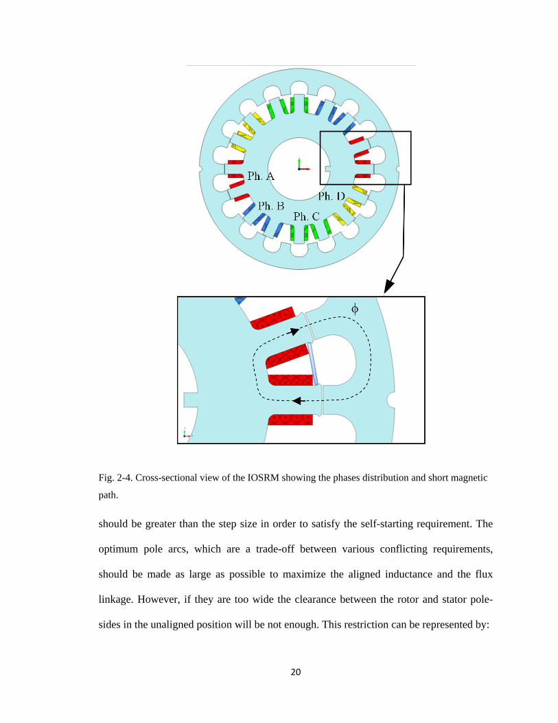
Fig. 2-4. Cross-sectional view of the IOSRM showing the phases distribution and short
magnetic path. ................................................................................................................... 20
Fig. 2-5. FEA solution for the sequential excitation of all phases and the corresponding
motion of the outer rotor. .................................................................................................. 23
Fig. 2-6. The saturation characteristics of the proposed motor obtained while varying the
rotor angular position over one stroke by step of 2 degrees. ............................................ 23
Fig. 2-7. The field solution of an 8/6 conventional SRM FEA model built with similar
size and power rating to the IOSRM................................................................................. 24
Fig. 2-8. Output torque obtained by both the machines over one single stroke at rated
current of the machines. .................................................................................................... 24
Fig. 2-9. Output torque showing large overlapping with no dead torque zones. .............. 25
Fig. 2-10. The conventional SRM model rotated by 22.5 degrees in order to align its
radial forces along the Y axis. ........................................................................................... 26
Fig. 2-11. The IOSRM model showing the excited winding aligned with the Y axis.in
order to capture the radial forces. ..................................................................................... 26
Fig. 2-12. Static FEA showing the radial force experienced by the conventional SRM
model................................................................................................................................. 26
Fig. 2-13. Static FEA showing the radial force experienced by the IOSRM model. ........ 27
Fig. 3-1. The proposed switched reluctance motor. (a) Whole motor. (b) Rotor. ............ 30

xiii
Fig. 3-2. Overview of the proposed motor. ....................................................................... 30
Fig. 3-3. Reluctance force components of radial field motor. .......................................... 32
Fig. 3-4. Reluctance force component of proposed motor. ............................................... 32
Fig. 3-5. Short magnetic flux-path. ................................................................................... 37
Fig. 3-6. Geometry parameters of the proposed SRM. ..................................................... 37
Fig. 3-7. Five phases inductance profile. .......................................................................... 37
Fig. 3-8. 3-D sketch for one stator c-core of the proposed motor, showing the dimensions
and the orientation of laminations. .................................................................................... 38
Fig. 3-9. The magnetic flux lines in the air-gap represented by flux tube. (a) For full
aligned rotor position. (b) For full unaligned position. ℜp1 and ℜp2 represent the
reluctance of the two poles of single c-core, ℜc-back is the back core reluctance, ℜc1 and
ℜc2 represent the reluctance of the corresponding cube. ................................................... 47
Fig. 3-10. The magnetic circuit model for single c-core and two cubes in a full unaligned
position. ............................................................................................................................. 47
Fig. 3-11. The available area for winding (slot area) of one c-core. ................................. 51
Fig. 3-12. Stages of coil design optimization. ................................................................. 53
Fig. 3-13.he current through one c-core coil obtained by 3-D FEA models at fixed speed
of 2,400 rpm, and for different number of turns. .............................................................. 54
Fig. 4-1. 3-D model. (a) One c-core wound by a phase coil and a slice rotor disc enclosing
the rotor cube. (b) 3-D model solution for the flux density for 75 A at 62% alignment. ... 57
Fig. 4-2. Comparison of the magnetizing characteristics of the proposed design at aligned
and unaligned positions by 2-D and 3-D FEA models (N=40). ......................................... 58
Fig. 4-3. Shaft torque by single c-core at two different current excitations calculated by 2-
D and 3-D FEA models (N=40). ....................................................................................... 58
Fig. 4-4. End winding as part of the complete winding for square cross-sectional c-core. 59

xiv
Fig. 4-5. The proposed pole shape modification. (a) 3-D model of the c-core showing the
flux fringing on the the front and side surfaces. (b) The close-up of modified shape shows
longer flux path. (c) The close-up of original shape shows shorter flux path. ................. 61
Fig. 4-6. Modifications on the 3-D model. (a) The improved pole shape. (b) The superior
design with rectangular cross-section of the c-core. .......................................................... 61
Fig. 4-7. The magnetization characteristics for the original design, the improved pole
shape design, and the superior design (N=40). ................................................................. 62
Fig. 4-8. Shaft torque provided by single coil, calculated by 3-D FEA for the original pole
geometry, the improved and the superior designs for two different current values. ........ 63
Fig. 4-9. Single phase asymmetric bridge converter is linked to the 3-D FEA model to
energize one c-core coil. ................................................................................................... 64
Fig. 4-10. Voltage and current waveforms of a single coil , obtained at speed below the
base speed. The current is regulated by current hysteresis method. ................................. 65
Fig. 4-11. The flux linkage trajectories against current obtained by 3-D FEA models
under transient (motion) analysis, for three different speeds. ........................................... 66
Fig. 4-12. Set of current traces obtained by varying the firing angle positions in
accordance with different motor speeds. .......................................................................... 67
Fig. 4-13. The output torque profile for three consecutive phases showing the individual
contribution from each phase. ........................................................................................... 68
Fig. 4-14. 3-D FEA model solution for the purpose of obtaining forces along the X-Y-Z
axes. Due to the symmetry in the 3-D model, only one halve of the model is sufficient
representation of one complete c-core. ............................................................................. 69
Fig. 4-15. Comparison of the radial forces of the in-wheel radial SRM, the convential
radial SRM, and the axial force of the axial SRM. ........................................................... 69
Fig. 4-16. The ASRM power and torque-speed characteristics. ....................................... 70
Fig. 5-1. C-core development. (a) Final version of the 3-D FEA model showing the shaded
plot of the magnetic flux density of single c-core at full alignment. (b) The corresponding
prototype during winding process. .................................................................................... 72

xv
Fig. 5-2. Prototype core components. (a) Proposed c-cores arrangement of the novel
ASRM design. (b) An individual c-core with dimensions. Welding locations are marked
by arrows. .......................................................................................................................... 72
Fig. 5-3. Rotor construction and assembly. (a) Isometric view of the final assembly. (b)
The cross-section view of the rotor disc ............................................................................ 74
Fig. 5-4. The area of high shear stress in the rotor disc. .................................................... 75
Fig. 5-5. The Mechanical CAD drawing of the assembled prototype (dimensions are in
mm). (a) Side view. (b) Front view. .................................................................................. 77
Fig. 5-6. Prototype development. (a) Final assembly showing one c-core removed. (b)
Experimental setup for obtaining the magnetization characteristics. ................................ 77
Fig. 5-7. Comparative analysis of the magnetization characteristics as obtained from
experiments and 3-D FEA simulations (N=60). ............................................................... 78
Fig. 5-8. Heat run test setup; deep-cycle lead-acid batteries supplying 40 A to the
prototype winding, thermometer is showing 45°C after 30 minutes. ................................ 79
Fig. 5-9. Experimentally-measured temperature rise of the prototype winding starting from
the ambient temperature, and recorded every minute till thermal equilibrium is reached.
The excitation current is 40 A. .......................................................................................... 80
Fig. 5-10. Experimental setup of the ASRM coupled to the loading machine. ................. 81
Fig. 5-11. Experimentally-measured shaft torque and corresponding current provided by
single coil. ......................................................................................................................... 82
Fig. 6-1. The magnetic circuit model for single c-core and two cubes in a full unaligned
position. ............................................................................................................................. 85
Fig. 6-2. A new winding method. (a) Coil dimensions. (b) Conventional winding wire vs.
square cross-section winding wire for optimum fill factor. .............................................. 86
Fig. 6-3. Test structure constraining a c-core with the coil cross section area smaller than
that of the original coil by 25%......................................................................................... 87

xvi
Fig. 6-4. Comparative analysis of the magnetization characteristics of a single c-core with
special winding configuration as obtained from experiments and 3-D FEA simulations. 87
Fig. 6-5. Orientations of the segmented grain oriented c-core used in the design. ........... 88
Fig. 6-6. Isometric view of the square cross-section coil wound around the c-core. ....... 91
Fig. 6-7. Top view of the coil end of a square cross-section c-core showing four layers. 92
Fig. 6-8. Magnetic solutions of the C-core models with and without the magnetic shields.
........................................................................................................................................... 95
Fig. 6-9. Flux linkage profiles of different C-core designs incorporating the proposed
leakage flux reduction approaches. ................................................................................... 97
Fig. 6-10. Torque profiles of different C-core designs incorporating the proposed leakage
flux reduction approaches. ................................................................................................ 97
xvii
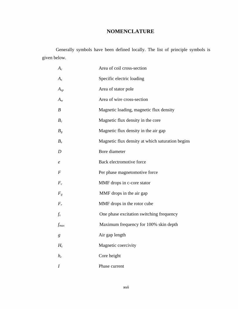
NOMENCLATURE
Generally symbols have been defined locally. The list of principle symbols is
given below.
Ac Area of coil cross-section
As Specific electric loading
Asp Area of stator pole
Aw Area of wire cross-section
B Magnetic loading, magnetic flux density
Bc Magnetic flux density in the core
Bg Magnetic flux density in the air gap
Bs Magnetic flux density at which saturation begins
D Bore diameter
e Back electromotive force
F Per phase magnetomotive force
Fc MMF drops in c-core stator
Fg MMF drops in the air gap
Fr MMF drops in the rotor cube
fs One phase excitation switching frequency
fmax Maximum frequency for 100% skin depth
g Air gap length
Hc Magnetic coercivity
hc Core height
I Phase current
xviii
i Instantaneous phase current
Imax Maximum current supplied by the SRM drive
Ir Rated current
is Current at which saturation begins
Ksf Fill factor
Ku Constant relates the inductance ratio
kd Duty cycle constant
ke Efficiency constant
L Winding inductance
La Aligned inductance
uaL Aligned unsaturated inductance
uL Unaligned inductance
lc Coil length
lcore Length of flux path through the core
lr Rotor cube line along the radial axis
lt Rotor cube line along the tangential axis
mmf Magnetomotive force
m Number of phases conducting simultaneously
N Number of turns per coil
Nph Number of SRM phases
Nr Rotor speed (rpm)
Nrep Number of phase repetition
Nst Number of strands per coil

xix
P Output power
Pr Number of rotor poles
Ps Number of stator poles
R, Rph Phase resistance
r Radius, Rotor cube to shaft distance
rir Rotor inner radius
ror Rotor outer radius
ros Stator outer radius
T Torque
Tav Average torque
TInstmax Maximum instantaneous torque
TInstmin Minimum instantaneous torque
TR Torque ripple
tr Rotor thickness
tc Core thickness
Ts Per phase switching period
V Single phase terminal voltage
Vs Voltage of the source
Wc Core width
Wco Coenergy
Wm Mechanical work
a Ratio of aligned to unaligned inductances
βr Rotor pole arc
βs Stator pole arc

xx
ε Step angle
ℜ Magnetic reluctance
ℜc-back Reluctance of the back core of a c-core
ℜp Reluctance of a pole of single c-core
ℜc Reluctance of the rotor cube core
ℜf The air-gap fringing reluctance
ℜpc Pole-to-cube reluctance
ℜl Leakage flux reluctance
ρ Electrical resistivity of conductor material
τr Rotor pole pitch
τs Stator pole pitch
τspp Stator pair-pair pitch
µ Magnetic permeability of the core material
µ0 Magnetic permeability of the free space
φ Magnetic flux
φr Remnant flux
θ Angular rotor position
θι Current conduction angle
ωm Motor angular speed
ωb Motor angular base speed
ψ Single phase flux linkage
1
Chapter 1
1. INTRODUCTION
1.1 Overview
The advancement of electric vehicle (EV) and hybrid electric vehicle (HEV)
technology has been significant in the past decade owing to improvements in motor
design, power electronics, and control and battery technologies. EVs and, to an extent,
HEVs are alternatives to gasoline and diesel automobiles, which are known to cause
pollution, including particulate matter and other smog-forming emissions. Automobiles
contribute to more than half of the CO and NOx, and almost a quarter of the
hydrocarbons emitted into our air [1]. This air pollution carries substantial risks for
human health and disturbs the ecosystem balance. Through clean vehicle and fuel
technologies, air pollution and its subsequent effects can be reduced significantly, while
cutting projected oil use in half within the next 20 years. Switching from gasoline cars to
plug-in hybrids that can be recharged by existing utility grids would lead to 42 percent
national average reduction in CO2 emissions by 2020, even though the majority of the
utility grid uses fossil fuels [2], suggesting that usage of EV, which are zero emission
vehicles, will reduce the emissions even further.
Growing transportation costs and upcoming regulations have increased the focus
on vehicle fuel efficiency and emissions control, emphasizing a need for more aggressive
research addressing the complex interactions of advanced powertrain technologies.

2
Electric traction systems account for 16% of overall losses in all-electric vehicles over an
Urban Dynamometer Driving Schedule (UDDS) drive cycle, which is used for testing
city driving conditions for light-duty vehicles. Most of these losses arise from the traction
motor, according to an ORNL report [3]. Therefore, improvements are focused on motor
design and motor materials that have the potential to significantly improve motor
efficiency and performance considering constraints such as size, weight, and cost.
Research objectives in the field of automobiles are consistent with the world’s
energy initiative to reduce dependency on oil and deliver consumers with affordable and
environmentally-friendly transportation choices. The increase in transportation efficiency
is the best place to start efforts to reduce emissions and emission related issues.
1.2 Background Literature on EV Motor Technology
A combination of new design variations, new materials, and sophisticated
electronic controls are making electric motors much more agreeable for EV duty.
Compared to industrial motors, EV motors require wider speed range and high torque and
power densities [4]. The design of an appropriate electric motor for EV depends on the
following factors: a) vehicle type, b) the driving profile and type of route followed, in
terms of the acceleration demand, climbing and braking performance, maximum speed
and range, c) vehicle constraints such as weight, and volume based on vehicle type, d)
efficiency, power density (power output/volume), reliability and cost, and d) type and
specifications of the energy storage unit. These objectives have to be achieved through
essential modifications in terms of design, material selection, innovative component
shapes and designs, and control strategies for electric motors to improve efficiency and

3
decrease cost and NVH (noise, vibration and harshness), while maintaining compact size
and light weight.
Performance of an EV relies on the design and appropriate control of its electric
propulsion system that consists of a traction motor, its power electronic drive, motor
controller, and an energy storage element, such as a battery. Recent efforts are directed
towards developing an improved propulsion system for EV applications.
Developing a high-performance electric motor strongly relies on its design. Few
factors that optimum design is required to possess are high efficiency, high power
density, wide speed ranges, and low torque ripple and noise. Consideration of machine
losses leading to lower efficiency is important for three reasons: losses appreciably
influence the machine operating cost; determine the heating of the machine and, hence,
the rating or power output that may be obtained without undue deterioration of the
insulation; and the voltage drops associated with supplying the losses. The materials used
in the design should have extremely low magnetization losses, a high degree of ability to
integrate, lead to high thermal capacity of the motor that result in longer motor life and
higher loading, and less and faster production steps.
Selection of a suitable electric motor to fulfill all the requirements for EV
application continues to pose a challenge [4]. Several motors have been analyzed for
traction purposes [5]-[8] amongst which induction motors (IMs), permanent magnet
synchronous motors (PMSMs) and switched reluctance motors (SRMs) are considered
the most fitting candidates.
4
Focus Electric 2013 shares Ford’s global C-car platform and is based on the
glider of the third generation Ford Focus. The electric car is powered by a PMSM rated at
100 kW and uses a 23 kWh capacity lithium-ion battery pack, which together delivers
245 Nm of torque.
Nissan utilizes an 80 kW AC synchronous motor in its all-electric vehicle known
as the “Leaf”. The Leaf has a driving range of 100 miles/charge based on the US EPA
City Cycle. Nissan has also developed a high power density 3D axial-flux type PMSM
that is capable of producing a maximum power of 135 kW [9].
The Chevy Volt plug-in HEV employs a 110 kW, 9,500 rpm, 12-pole PMSM and
a 55 kW, 6,000 rpm, 16 pole permanent magnet AC synchronous generator in the
vehicle’s drivetrain with a shaft torque of 370 Nm and 200 Nm, respectively. Both the
machines of the Voltec electric drive system are interior permanent magnet machines
with the motor having a distributed winding and the generator having a concentrated
winding in their respective stators.
The BMW i3, previously Mega City Vehicle (MCV), is a 5-door sedan urban
electric car developed by BMW. Under the New European Driving Cycle the official
range is 130 to 160 km and up to 200 km in the most efficient driving mode. The three-
door coupe, like the five-door i3 electric sedan, is propelled by an electric motor
developed by the BMW Group, with a maximum output of 125 kW and peak torque of
250 Nm.
The Tesla Roadster employs an AC induction motor (IM) that produces high
torque at very low rpm and delivers constant acceleration up to 6,000 rpm. Raser’s

5
Symetron P-42 IM [10] can deliver high efficiency and high torque over a wide operating
speed range. This motor has a pancake shape for easy integration.
Honda vehicles are focused on surface PM and inset PM machines with
segmented stator structures and fractional-slot concentrated windings. Segmented
structures not only have the potential for increasing copper slot factor and reducing
manufacturing costs, but they also compromise the stator back iron rigidity. The Honda
designs tend to have low winding factor of 0.866. Honda has developed a thin 15.5 kW
PMSM for its Civic Hybrid that uses inset permanent magnets in its rotor, concentrated
windings in its stator, and displays a very high efficiency. Also, it can be noted that the
Honda designs utilize low DC bus voltage. The machines are designed for tight
integration with the ICE-drivetrain housing.
Although permanent magnet machines seem to be the most common motor
technology used by major automakers, demerits such as the high current for field-
weakening operation, temperature sensitivity, costly magnet, demagnetization of the
permanent magnets due to high temperatures, and fabrication difficulties are leading to
researchers looking for better options, preferably non-magnet designs [11].
The Squirrel cage IMs are one of the magnet-free motor contenders for the
electric propulsion of EVs for their reliability, ruggedness, low maintenance, low cost,
and ability to operate in hostile environments. IMs are considered suitable for HEVs
owing to their reliability, low cost, and wide speed ranges at constant power. Low
efficiency of IMs, mainly owing to copper losses from stator and rotor and subsequent
increase in heat is a major limitation in traction application for which several optimal

6
flux and loss minimization control techniques are proposed [12]-[14]. Other drawbacks
include low power factor, and low inverter-usage factor, which is more serious for the
high speed, large power motor. One of the most critical problems posed by IM is the
presence of breakdown torque limit while operating in extended constant-power
operation where at critical speed the breakdown torque is reached. Modifications at the
design level and fault tolerant, high performance control techniques are proposed to
improve the speed and torque response of IM drives [12]-[15].
It can be observed from the above content that all of the automakers are trying to
develop better traction motors through extensive research and development activities as
the search for the optimized vehicle traction motor is still continuing. More robust and
cost efficient machines, such as switched reluctance motors (SRMs), have potential for
the future of automotive applications.
1.3 SRM Research Background
As a magnet free motor with a simple and rugged construction, high speed
operation and extended constant power range, SRMs are gaining interest as a potential
alternative in EV traction [11], [16]-[18]. SRM is a doubly salient machine with no
winding, magnet, or conductive bars on the rotor. It features a simple structure,
ruggedness, fault-tolerance ability, high-speed operation capability, high power density,
and low manufacturing cost. Owing to the absence of rotor excitation, they are not
susceptible to rotor winding failures or demagnetization of the magnets and are excellent
candidates for automotive applications, especially for heavy duty electric buses [19]-[21].

7
Also, in electric drivetrains, the machine has a niche performance over a wide speed
range on accurate design and control.
Despite these advantages, there are challenges. For example, torque ripple and
acoustic noise need to be addressed through fundamental design improvements in order
to develop a viable SRM-based electric propulsion system. Extensive research has
focused on the design of conventional radial-flux SRMs, such as the new configuration
with a higher number of rotor poles than stator poles tending to increase the torque per
unit volume [22]. Desai et al., 2010, observed that machines with increased number of
poles without increasing the number of stator phases have shown superior performance
with higher torque per unit volume, lower manufacturing costs and comparable torque
ripple when compared to a conventional SRM. A novel two-phase SRM with E-core
stator was also proposed in [23]. The E-core stator consists of three poles with two poles
at the ends having windings and a center pole containing no copper windings. During the
operation, the center stator pole is shared by both phases. The uniqueness of the design is
that while the air gap around the common stator pole has constant and minimum
reluctance, irrespective of rotor position, the two remaining stator poles at the ends
experience variable reluctance with respect to the rotor position. Its major advantages
were in saving the stator core and eliminating the flux reversal in the stator, hence
reducing core losses. More novel designs were presented in [24] and [25], which focused
on the radial SRM configuration. In [24], a novel SRM was designed for low-cost
production that possessed high slot space for easy coil winding and was found to have
better characteristics in terms of torque and efficiency and in [25], a multi-objective
optimization procedure and an analytical model derived from reluctance network method

8
was developed to design a 6/4 type SRM to be employed in EV drive. Research was also
conducted on linear SRMs [26], [27]. Linear SRMs gained interest due to the fact that
unlike the rotating machine, with only the tangential component force, usually called
torque, the linear machine has propulsion, guidance, and normal forces that affect its
dynamic motion in three degrees of freedom (3-DOF). However, very little attention has
been given to the design of axial-flux switched reluctance motors (ASRMs) [28]. The
design in [28] has a complicated structure requiring the use of ferromagnetic material,
and hence the design will not be efficient for high power rating.
Further background literature related to research performed in this thesis has been
provided separately in corresponding chapters.
1.4 Research Objective
The recent interest by the automotive industry in finding an electric motor that has
high power density, rugged construction with high temperature adaptability, lower cost,
and fault tolerance ability has changed the map of electric motors and revived the research
on switched reluctance motors (SRMs). Due to the aforementioned characteristics and
several other features [20], SRMs are considered to be an attractive alternative to
traditional electric motors in electric and hybrid electric vehicle applications.
In spite of the said advantages, there are, however, a few challenges such as torque
ripple and acoustic noise that need to be addressed in order to develop a viable SRM-
based propulsion system. Hence, the research objectives of this dissertation are to analyze,
investigate, and address the challenges of torque ripple and acoustic noise through

9
fundamental design improvements keeping the aforementioned industrial targets in
parallel.
1.5 Research Contributions
1) Designing and analyzing of a short-flux path outer rotor SRM for an in-wheel
drive application aimed for reduction in torque ripple. The proposed machine had reduced
torque ripple and higher efficiency than that of the conventional SRM.
2) Designing, prototyping and analyzing a novel 5-phase pancake shaped axial flux
SRM to address issues in acoustic noise, vibration and torque ripple while keeping merits
of the previously investigated short-flux path configuration. The comprehensive design
procedures included a new systematic approach for deriving the output power equation of
a unique and newly targeted topology of axial flux machine. It also provides a winding
design approach for the process of coil optimization.
3) Investigation of leakage flux in axial flux SRM through novel flux tubing
approach and experiments incorporating the 3-D effect and leakage component.
4) Solutions based on new methods of utilizing segmented grain-oriented silicon
steel core material for mitigating issues related to leakage flux.
5) Shielding and winding configuration based methods to alleviate issues related to
leakage flux.
1.6 Dissertation Outline
The remainder of this dissertation is organized as follows.

10
Chapter 2 provides a brief background study of the fundamental operating principle and
introduction to radial and axial flux SRMs. Threreafter, a case study based on finite
element analysis is presented in this chapter in detail to analyze and quantify the major
well-known issues of SRM, namely the torque ripple and acoustic noise. The case study
deals with two types of SRM designs, one is a commercially available conventional SRM
and the other is a new design of in-wheel outer-rotor SRM for EV application. This
chapter illustrates the design aspects and discusses the results from comparative
performance analysis of both the conventional SRM and the outer rotor SRM.
Chapter 3 firstly illustrates the concept of an axial-flux SRM and describes the key
features of the novel five phase pancake shaped SRM proposed. Thereafter, the motor
design procedure employed is explained in details along with coil design and
optimization tasks undertaken in this thesis.
Chapter 4 presents results obtained from static and dynamic finite element analysis
performed on the designed motor. It also provides a comprehensive comparative
performance analysis between the 2D and 3D models of the machine. An optimal model
of C-core is obtained.
Chapter 5 presents the steps involved in the prototyping process of the designed axial
flux SRM. It also presents and discusses results obtained from experimental
investigations performed on the prototyped machine.
Chapter 6 illustrates the issues related to leakage flux elicited from experimental and
theoretical analysis conducted on the proposed machine through a flux tubing technique.

11
Thereafter solutions based on materials, shielding and winding configurations has been
presented in order to reduce the leakage flux.
Chapter 7 provides conclusions and findings of this dissertation.
12
Chapter 2
2. DESIGN AND INVESTIGATION OF RADIAL FLUX SWITCHED
RELUCTANCE MACHINES
2.1 Chapter Objectives:
In addition to the background literature review presented in Chapter 1 illustrating
previous research activities performed in the area of SRMs, a case study based on finite
element analysis is presented in this chapter in detail to analyze and quantify the major
well-known issues of SRM, namely the torque ripple and acoustic noise. The case study
deals with two types of SRM designs, one is a commercially available conventional SRM
and the other is a new design of in-wheel outer-rotor SRM for EV application. Both of
the designs have radial flux patterns and equivalent power ratings; however, they differ in
their individual flux paths. The current chapter illustrates the design aspects and discusses
the results from comparative performance analysis of both the conventional SRM and the
outer rotor SRM.
2.2 Introduction and Operating Principle of SRM:
The switched reluctance motor is a doubly-salient singly-excited synchronous
machine. It has the simplest motor construction which offers benefits over the
conventional motor technologies. The laminated stator stack is analogues to that of the
DC motor, where concentrated coils are wound around the stator poles. The rotor is

13
simply a core of laminated soft magnetic steel with no permanent magnets, conducting
bars, or windings on it; hence, brushes are not required as well. Owing to the latter, SRM
rotor has a low moment of inertia, thus, giving a large acceleration rate for the motor and
superior dynamic response [29].
The reluctance torque is generated through the tendency of the rotor to move to its
minimum reluctance position with respect to the excited stator pole. The minimum
reluctance is usually reached when the excited stator pole is in full alignment with the
rotor pole. Generally, the rotor poles are shaped in such a way as to maximize the
variation of inductance with position.
In order to maintain the generated torque of the motor in one direction (positive
torque), the windings of successive stator poles should be excited in sequence so that the
magnetic field of the stator leads the rotor pole, pulling it forward.
2.3 SRM Classification and Configuration
Based on the orientation of their electromagnetic flux path with respect to the axis
of their shafts, SRMs are classified as “Radial SRMs” if the magnetic flux path penetrates
the rotor along the radius of it, while traveling from one stator pole to the opposing one.
When the flux path through the rotor body is along the axial direction, the machine is
then called an “Axial-Flux SRM.”
Depending on the length of the flux path through the rotor, there are short-flux
path SRMs versus the long flux path ones that are conventional SRM. The flux path is
determined by the winding coils layout design. In the long flux path, the two coils

14
forming one phase are placed around the diametrically opposite poles. While in the short
flux, the two coils are usually wound around adjacent stator poles.
Short-flux path SRMs have the advantage of lower core losses due to the fact that
the flux reversals do not occur in stator back iron. They are ideal for applications where
the total length may be constrained, such as in a ceiling fan or in a propulsion application.
The variety of combinations of number of phases with stator and rotor number
and shapes of poles led to a wide range of possible designs of the SRM. Fig. 2-1. shows
two topologies of SRM; a conventional radial 8/6 SRM, and a 12/8 short flux radial
SRM. There are various configurations of SRM designs, which were proposed to improve
the overall performance of the machine, e.g. a c-core stator was proposed in [30].
(a) (b)
(c) (d)
Fig. 2-1. Switched reluctance motor topologies. (a), conventional radial 8/6 SRM, (b) short flux
radial 12/8 SRM,(c) isometric view of 8/6 SRM, and (d) the actual stator of the 8/6 SRM.

15
2.4 Case study: Outer Rotor SRM versus 8/6 Conventional SRM
2.4.1 Objective
In this era of electrified transportation, switched reluctance motor (SRM) is
emerging as a prospective replacement to traditional electric motors especially for large
heavy duty vehicles such as the electric bus. Previous research indicated that the in-wheel
outer rotor motor has an edge over the conventional motor designs for the electric vehicle
application as it saves substantially large space previously occupied by the necessary
mechanical components such as the transmission, speed reducer shafts and differential
[31]-[34]. Bullis 2009, indicated that the in-wheel motor was instrumental to improve the
efficiency of the electric bus as the bus could travel twice as far as a conventional bus on
a liter of diesel. The in-wheel motors conferred additional savings by eliminating the
need for a transmission, differential, and related mechanical parts. As a result, both the
overall weight of the bus and energy losses due to friction are reduced. The in-wheel
motors also improved traction by allowing precise control over each wheel, and they
allowed greater flexibility in vehicle design since there was no need to mechanically link
the wheels to an engine [35].
This case study proposes the design and analysis of a novel outer rotor in-wheel
SRM (IOSRM). The integration of the motor housing inside the wheel rim saves
significant space and eliminates the need for additional mechanical parts used in the
centralized drive. The procedures of deriving the output power equation as a function of
the motor dimensions and parameters are explained in [36]. Comparative finite element

16
analysis (FEA) is performed between the developed machine and a commercially
available conventional SRM.
2.4.2 Concept of the Proposed In-wheel Outer Rotor SRM and its Features
Figure 2-2 shows the isometric perspective illustration of the proposed SRM
integrated in a wheel of electric bus. The shaft of the stator core is rigidly fixed to a beam
of the rear suspension system. The outer rotor is mounted on the stationary components
by a set of bearings that facilitate the spinning of the rotor. The rotor core is firmly
fastened to the wheel’s rim by an arrangement of bars and two end rings as shown in Fig.
2-3. This design has 18 rotor teeth and 16 stator poles. The rotor teeth are evenly
distributed with 20 degrees spacing. The stator poles are formed of 8 pairs as shown in
Fig. 2-4. The angular distance between the axes of each adjacent pair is 45 degrees.
Moreover, the angular distance between the poles within the pair is 20 degrees.
The windings of each phase are split on 4 concentrated coils wound in series
around 4 stator poles, two on each side diametrically. Upon excitation, the magnetic
circuit of each phase is formed by a pair of stator poles facing two aligned rotor teeth as
shown in Fig. 2-4. The torque production in this design relies on the tendency of the
excited stator poles to pull the nearby rotor teeth into alignment. An important feature of
this design topology is that it offers very short flux path thus minimizing the iron loss
without compromising the high power capability of the motor. In addition, a minimum of
four poles are energized at any given time, which renders this machine at least double the
torque capability of the conventional SRM. Additional features of the proposed design
are summarized as follows:

17
Fig. 2-2. The complete in wheel drive arrangement.
• The main advantage of using an integrated in-wheel outer rotor electric drive is that
it saves substantial space previously occupied by the necessary mechanical components
such as the transmission, speed reducer shafts and differential.
• The flux path is independent of the radius of the rotor. This particular feature gives
the designer the capability of increasing the torque by increasing the radius of the rotor
without having to increase the flux path ( rF ×=τ ), where F is the reluctance force
generated in the air-gap and r is the radius of the air-gap.
Liquid cooling tubes
Suspension
Ring
Stator and Winding
Rotor
Rim and Bars
Tire

18
Fig. 2-3. The geometric parameters of the proposed IOSRM.
• In conventional SRM, one magnetic circuit is shared by all phases, and the
windings of two adjacent phases are fitted together in one slot. These contribute to the
mutual coupling between adjacent phases. This disadvantage is minimized in this design
since each phase has an independent magnetic circuit, and the winding of different phases
are further separated.
• The direction of the flux in the stator poles is always the same. In other words, the
flux reversal does not occur, hence lowering the core losses compared to conventional
SRM [37].
• Enough spacing between the adjacent magnetic circuits on the stator makes it
possible to include liquid cooling tubes as shown in Fig. 2-2. This pacifies most of the
heat generated by the stator coils, and, therefore, permits a higher current rating, which in
turn increases the output power rating of the machine.
• The insertion of cooling tubes has an additional important advantage as it serves as
a flux barrier that limits the mutual coupling and the leakage flux between two magnetic
βs

19
circuits excited at the same time. Therefore, it increases the overall efficiency of the
machine and improves its performance.
2.4.3 Geometrical Design of the Proposed IOSRM
Considerable research has been done to alleviate the problem of torque ripple in
SRM by proposing intelligent control schemes [38]. Yet, the geometrical structural
solution is preferred over the control scheme. Many literatures have suggested large
number of phases or poles [39]. The motor in this case study is designed with outer rotor
and large number of poles. Consequently, the number of strokes per revolution increases,
and the torque ripple problem could be alleviated. The increased number of poles requires
a larger diameter, resulting in a greater flux-path length which in turn raises the losses
and reduces efficiency. The solution for the problem is addressed by adopting a shorter
flux-path as shown in Fig. 2-4.
A small step angle of 5 degrees is achieved by adopting the configuration
explained in this chapter. The step angle is calculated using the following:
rph NN ×
°=ε
360
(2.1)
where, Nph and Nr are the number of phases and the number of rotor poles, respectively.
Generally, the initial design process goes through several iteration steps. Several
geometries have been calculated with varying pole numbers and pole dimensions,
keeping in mind that a number of requirements need to be fulfilled such as; minimizing
the step size (ε), the self-starting capability, and the optimum pole arcs. The stator arc (βs)
20
Fig. 2-4. Cross-sectional view of the IOSRM showing the phases distribution and short magnetic
path.
should be greater than the step size in order to satisfy the self-starting requirement. The
optimum pole arcs, which are a trade-off between various conflicting requirements,
should be made as large as possible to maximize the aligned inductance and the flux
linkage. However, if they are too wide the clearance between the rotor and stator pole-
sides in the unaligned position will be not enough. This restriction can be represented by:

21
Table 2-1. DIMENSIONS OF THE PROPOSED IOSRM
Number of phases Nph 4 Air-gap length g 0.9 mm
Stator-rotor configuration 16/18 Motor axial length lm 180 mm
Rotor pole pitch τr 20° Stator outer radius ros 134.1 mm
In-pair stator pole pitch τs 20° Rotor inner radius rir 135 mm
Stator pair-pair pitch τspp 45° Rotor outer radius ror 180 mm
Stator pole arc βs 8° Number of turns N 160
Rotor pole arc βr 8° Step angle ε 5°
srrN
β⟩β−π2 (2.2)
The optimum pole arcs are somewhere between these extremes [39]. An adequate
choice for this design was to have both stator and rotor poles’ arcs equal. The main
dimensions are presented in Table 2-1, and illustrated in Fig. 2-3.
Further details including the output power derivation are provided in [37].
2.4.4 Comparative Finite Element Analysis of the IOSRM and the Developed
Conventional SRM
The FEA model of the proposed IOSRM design is built using MagNet Infolytica
software. Details on finding the optimum magnetomotive force and winding design are
provided in details in [36]. The static analysis is used to derive the operating current and
to validate the correctness of the design. The sequential excitation of the motor phases

22
causes rotation of the outer rotor in counter clockwise direction. The color coded solution
plot given in Fig. 2-5 shows satisfactory level of local saturation in the regions of the
overlapped poles. The magnetization characteristics, the most descriptive illustration of
the motor performance and efficiency, are obtained and presented in Fig. 2-6. It can be
seen that the value of inductance ratio at the rated current (ratio of aligned flux linkage to
the unaligned one at a specific current) is relatively high for a motor with large number of
poles based on comparison with the results in [40], and [41]. High inductance ratio is
directly reflected in the output power, hence validating the design with respect to the
efficiency improvement. The IOSRM power ratings are listed in Table 2-2.
An FEA model of 8/6 conventional SRM with the same power rating and
identical related geometrical dimensions to the IOSRM is built for comparative analysis
purpose. Both models phases are current driven with the same values. The field solution
of the developed conventional SRM is as shown in Fig. 2-7. The output torque obtained
during single stroke of operation by both the machines is demonstrated in Fig. 2-8. Since
their poles arcs are not equal, the rotor positions scales are taken as per unit quantities of
each machine. The comparison in Fig. 2-8 illustrates the improvement in the output
torque and, hence, in the efficiency. Fig. 2-9 shows the output torque obtained by the
individual consecutive phases. The obvious large overlapping of 50% suggests that there
are no dead torque zones at the output. This is due to the small step angle in this design,
which is in turn governed by the large number of poles and special configuration design
of the poles. It can be concluded here, based on the large overlap between consecutive
phases torque profiles, this design can minimize the torque ripple to a very low level, by
applying basic control techniques that boost of the current at the low torque regions.

23
Phase A Phase B
Phase C Phase D Fig. 2-5. FEA solution for the sequential excitation of all phases and the corresponding motion of
the outer rotor.
Fig. 2-6. The saturation characteristics of the proposed motor obtained while varying the rotor
angular position over one stroke by step of 2 degrees.
0
0.22
0.44
0.66
0.88
1.1
0 10 20 30 40 50
Flux
Lin
kage
[W
B-T
]
Current [A]

24
Fig. 2-7. The field solution of an 8/6 conventional SRM FEA model built with similar size and
power rating to the IOSRM.
Fig. 2-8. Output torque obtained by both the machines over one single stroke at rated current of
the machines.
Table 2-2. Rating of the Proposed IOSRM.
Parameter Values Parameter Values
Output Power 24 kW Maximum power 40 kW
Rated torque 120 N.m Maximum torque 200 N.m
Rated current 35 A Base speed 2,000 rpm
-20
0
20
40
60
80
100
120
140
0 18 36 54 72 90 108 126 144 162 180
Torq
ue [N
.m]
Rotor position [electrical degree]
Proposed SRMConventional SRM

25
The developed FEA models solutions have also shown the radial forces
experienced by the motors structure. Radial forces are the main cause to the noise and
vibration in SRM [27], [42]. As observed in Fig. 2-10, the model of the conventional
SRM is rotated by 15 degrees in order to align its radial forces along the Y axis.
Similarly, the IOSRM is also rotated for the same purpose, as seen in Fig. 2-11. The
radial force seen at Y axis is provided in Fig. 2-12 for the conventional SRM and in Fig
2-13 for the IOSRM. These are static FEA tests under rated current and full alignment
position, and are sufficiently suitable for the purpose of comparison. While both designs
showed significant radial forces, the IOSRM showed slightly higher values.
Fig. 2-9. Output torque showing large overlapping with no dead torque zones.
0
20
40
60
80
100
120
140
0 5 10 15 20 25
Torq
ue [N
.m]
Rotor position [mechanical degree]
Phase A Phase B Phase C Phase D

26
Fig. 2-10. The conventional SRM model rotated by 22.5 degrees in order to align its radial forces along the Y axis.
Fig. 2-11. The IOSRM model showing the excited winding aligned with the Y axis.in order to capture the radial forces.
Fig. 2-12. Static FEA showing the radial force experienced by the conventional SRM model.
-1000
0
1000
2000
3000
4000
0 5 10 15 20 25
Rad
ial f
orce
[N]
Rotor mechanical angle [Degree]

27
Fig. 2-13. Static FEA showing the radial force experienced by the IOSRM model.
2.5 Conclusion
The results obtained through FEA investigations show good output torque profile
in term of low torque ripple, observed for a motor without applying any control
technique. The motor efficiency is also validated based on the satisfactory inductance
ratio’s value of approximately (4). The low torque ripple can be attributed to the
increased number of poles, and the satisfactory efficiency can be attributed to the short-
flux path configuration in the machine. However, the radial forces which accounts for the
acoustic noise and vibration are still high.
Hence, a major design modification in SRM technology is necessary in order to
keep the merits such as efficiency and reduced torque ripple and simultaneously
overcome challenges such as acoustic noise and vibration in the machine. This is one of
the key motivating points to design and investigate axial-flux SRMs whose design and
analysis is presented in the forthcoming chapters.
-1000
0
1000
2000
3000
4000
5000
0 2 4 6 8 10 12R
adia
l for
ce [N
]
Rotor mechanical angle [Degree]

28
Chapter 3
3. DESIGN OF A NOVEL 5-PHASE PANCAKE SHAPED AXIAL
FLUX SRM (ASRM)
3.1 Introduction
Electrified automotive industrial research on axial flux motors has significantly
increased in the last few years and been adopted by few automakers [9] due to its higher
torque density by both volume and weight as compared to the radial-flux configuration.
Axial flux machines utilize the active radial part effectively, as required in high
power density applications. For higher aspect ratio (outer diameter to overall axial length),
power density of axial flux machines is higher than that of radial flux machines. For in-
wheel EV applications, the torque requirement is high, but the size of the motor is
restricted by the wheel rim. Nissan Motors is investing largely in research for enhancing
the new configuration of axial flux PMSM that has high number of phases [9].
In [43], the authors have developed an axial flux segmented toroidal type winding
SRM for EV applications. The new design offered advantages of low copper losses and
end winding volume compared to conventional SRM.
Axial and radial SRMs generally share the same operating concepts and features,
except the orientation of the flux as it passes through the rotor; parallel to the axis of

29
rotation in axial motors and perpendicular in radial machines. Thus, the design
procedures vary due to this geometric dissimilarity.
In this chapter, a new design of axial-flux switched reluctance motor (ASRM) is
proposed. The motivation behind this novel machine design is to develop a viable axial
flux SRM for EV applications by addressing issues such as acoustic noise and vibration,
less torque ripple and yet keeping the efficiency and power density equivalent or better
than conventional radial SRMs.
3.2 Axial-flux SRM Concept and Description
The conceptual diagram for the proposed motor is shown in Fig. 3-1. The stator is
composed of 15 c-core, each of which has individually wound coil. The rotor which has a
disc shape could be made of any low magnetic permeability material. Through the rotor
disc, 12 square holes are created to be filled by 12 cubes of high magnetic permeability
material such as the silicon steel. The torque production in this design relies on the
tendency of any of these cubes (which can be considered as the rotor’s poles) to align
with the two poles of an energized c-core, providing the minimum reluctance path to the
magnetic circuit of one c-core. The motor has 5 phases and 3 repetitions as shown in Fig.
3-2, where the 15 cores on the stator are divided into 3 sets displaced by 120 mechanical
degrees for better forces distribution on the structure of the motor.

30
(a) (b)
Fig. 3-1. The proposed switched reluctance motor. (a) Whole motor. (b) Rotor.
Fig. 3-2. Overview of the proposed motor.
3.2.1 Torque Ripple Reduction
Toque ripple is defined as
Ave
InstInst
TTT
TR minmax−
= (3.1)
According to [44], the majority of torque ripple occurs in the phase overlap region
where the torque producing responsibility is commutated from one energized phase to

31
another. Poor overlap ratio (less than 10%) is the main cause of the torque ripple. The
overlap region is greatly influenced by the step size that is defined as follows
rph PN ×°
=ε360 (3.2)
where, Nph and Pr are the number of phases and the number of rotor poles, respectively.
It can be noted that both the number of phases and the number of poles are
required to be maximized for the purpose of reducing the torque ripple. However, to
adopt high number of phases or poles the diameter of the motor has to be increased which
in turn increases the flux path length and hence the losses increase, this is for the case of
conventional radial SRM.
In the proposed design, the flux path is independent of the rotor diameter.
Therefore, the latter can be increased to allow more space for higher number of poles
without affecting the magnetic loading. As a result of having a higher number of poles,
the step size is reduced which in turn results in minimizing the torque ripple.
3.2.2 Vibration and Acoustic Noise Minimization
According to literatures [27], [42], the acoustic noise in reluctance motors is
mainly generated by the electromagnetic radial force produced by excitation as seen in
Fig. 3-3 By examining the proposed design in Fig. 3-4, it can be seen that the reluctance
force developed at the rotor’s pole has only tangential components with no radial
component produced.; therefore the vibration and the acoustic noise in this design are
brought to a low level.

32
Fig. 3-3. Reluctance force components of radial field motor.
Fig. 3-4. Reluctance force component of proposed motor.

33
3.2.3 Key Features of the New Design
This design has additional features as compared with typical SRMs, they are
summarized as follows:
1. Higher torque and power density:
rmsude NlDBAkkkP 2120
π= (3.3)
where,
ke : the efficiency constant,
kd : the duty cycle constant,
ku : constant relates the inductance ratio ( sauu LLK /1−= ),
saL : the aligned saturated inductance per phase,
B, As : are the magnetic and electric loading respectively,
D : the bore diameter,
lm : the length of motor,
Nr : the rotor speed (rpm).
From (3.3), the standard output equation of SRM [37], it can be seen that
for a given magnetic and electric loading, the torque and power are
proportional to the square of the diameter. The proposed design has the
ability to increase the torque by increasing the diameter of the rotor,
without increasing the flux path length.
2. Larger space available for the coils gives the designer more flexibility in
determining the number of turns so the resistance and copper losses are
reduced unlike the conventional SRMs that are limited by the slot space.
This is illustrated in the specific electric loading formula [38]:
34
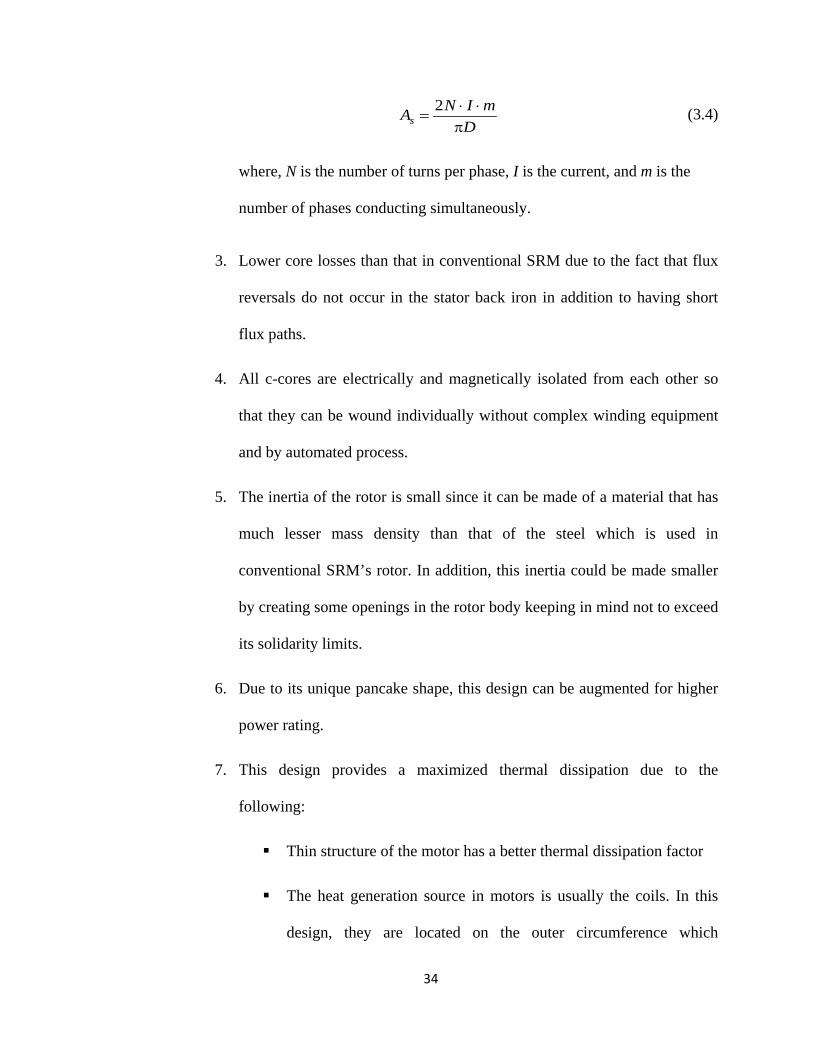
DmINAs π
⋅⋅=
2 (3.4)
where, N is the number of turns per phase, I is the current, and m is the
number of phases conducting simultaneously.
3. Lower core losses than that in conventional SRM due to the fact that flux
reversals do not occur in the stator back iron in addition to having short
flux paths.
4. All c-cores are electrically and magnetically isolated from each other so
that they can be wound individually without complex winding equipment
and by automated process.
5. The inertia of the rotor is small since it can be made of a material that has
much lesser mass density than that of the steel which is used in
conventional SRM’s rotor. In addition, this inertia could be made smaller
by creating some openings in the rotor body keeping in mind not to exceed
its solidarity limits.
6. Due to its unique pancake shape, this design can be augmented for higher
power rating.
7. This design provides a maximized thermal dissipation due to the
following:
Thin structure of the motor has a better thermal dissipation factor
The heat generation source in motors is usually the coils. In this
design, they are located on the outer circumference which

35
facilitates a faster and more efficient heat transfer to the outer
ambient
This special structure also enables it to adopt advanced cooling
systems such as water jacket around the motor case.
3.3 Motor Design Procedures
3.3.1 Geometry Design
The aim of the design is to provide a feasible solution to the well-known
drawbacks of SRMs namely the acoustic noise and torque ripple. This demerit is
particularly undesirable for the vehicle applications. A considerable work done in the
analysis of the acoustic noise suggests that the radial forces account for most of it as
mentioned earlier in this thesis. Therefore to meet this constraint, we designed a motor
with axial flux so that the magnetic forces are only in the tangential plane to the rotor
circumference, thus reducing the radial forces to a very low level.
And regarding the torque ripple, a possible solution according to [30] is to
consider higher number of phases so that the number of strokes per revolution increases;
as a result the torque dip problem could be alleviated. This solution is harder to achieve
in case of conventional SRM because increasing the number of phases requires larger
diameter resulting in a greater flux-path length which in turn raises the losses and reduces
efficiency. The solution for this was addressed in this design by adopting a shorter flux-
path as shown in Fig. 3-5.

36
The subsequent step of the design procedure was with the hand calculation of
several geometries with varying pole numbers and pole dimensions keeping in mind that
several requirements need to be fulfilled such as; minimizing the step size (ε) also known
as stroke in some literature, the self-starting capability, and the optimum pole arcs. In this
design, a small step angle of 6° was achieved, and calculated as in (3.2).
To achieve the self-starting requirement, the stator arc (βs) should be greater than
the step size (ε). The optimum pole arcs are a compromise between various conflicting
requirements. On the one hand they should be made as large as possible to maximize the
aligned inductance and the maximum flux linkage. However, if they are too wide there is
not enough clearance between the rotor and stator pole-sides in the unaligned position.
This restriction can be represented by:
srrP
β⟩β−π2
(3.5)
The optimum pole arcs are somewhere between these extremes. Generally, for
very high efficiency designs, the slot area needs to be maximized and this leads to a
narrower pole arc [39]. However, in the proposed design this problem does not exist as
there is enough space for the windings around the stator cores owing to its unique
topology as can be seen from the top view of the motor in Fig. 3-6. An adequate choice
for this design was to have both stator and rotor poles’ arcs equal. Fig. 3-7 shows the
ideal inductance profile for all phases. It can be noted that the overlap region was
increased to offer stronger self-starting capability, large output torque, and little torque
ripple. The main parameters and dimensions are presented in Table 3-1, and illustrated in
Fig. 3-6, and Fig. 3-8.

37
Fig. 3-5. Short magnetic flux-path.
Fig. 3-6. Geometry parameters of the proposed SRM.
Fig. 3-7. Five phases inductance profile.
lr
βr
βs

38
Fig. 3-8. 3-D sketch for one stator c-core of the proposed motor, showing the dimensions and the orientation of laminations.
Table 3-1. Motor Parameters.
Parameters Values The number of phases 5 The stator-rotor configuration 15/12
The rotor pole pitch τr 30°
The stator pole pitch τs 24° The rotor pole arc βr 9.6° The stator pole arc βs 9.6° The outer diameter of the rotor D 320 mm The radius of the centre of a rotor cube r 144 mm The air gap length g 0.3 mm The core height hc 93 mm The core width Wc 72 mm The core thickness tc 24 mm The rotor thickness tr 24 mm The stator pole depth ds 30 mm The coil length lc 45 mm Number of turns N 40

39
3.3.2 C-core Magnetic Circuit Design Analysis
In the proposed motor design, the fact of having completely separated magnetic
circuits represented by the c-cores simplifies the designing procedures as compared to the
conventional SRM. Considering one c-core along with one rotor cube that completes the
magnetic circuit as shown in Fig. 3-5, we can write the required magnetomotive force
(MMF) to produce the flux density in the air gap as well as the stator core and the rotor
cube, as follows
rcg FFFF ++= (3.6)
where, F is the total MMF per phase applied and Fg, Fc, and Fr are the MMF drops in the
air gap, c-core stator, and rotor cube respectively. In this design, the cross-section and
material of the stator and the rotor are identical. Therefore Fc and Fr can be together
considered as a part of the circuit, and equation (4.12) can then rewritten as
corecg lBg
BNiF
µ+⋅
µ==
0 (3.7)
where,
N : number of turns,
Bg: magnetic flux density in the air gap,
Bc: magnetic flux density in the core,
g: air gap length,
lcore: flux path length in the core and rotor cube,
µ : magnetic permeability of the core material,
0µ : magnetic permeability of the free space.

40
In the aligned position the phase inductance is at its maximum value because the
magnetic reluctance of the flux path is at its lowest. At low current levels, before the
saturation starts, most of the reluctance is in the air gap because the magnetic
permeability of the core material is much higher than that of the air ( 0µ⟩⟩µ ). In addition
to it, the flux path length in this design is relatively short, as a result, the second term on
the right-hand side of equation (3.7) can be neglected and the minimum required current
can be determined.
On the other extreme, working in the heavily saturated region is also not
recommended as it increases the iron losses which in turn reduce the efficiency. The
current at which this occurs will be obtained by utilizing the data from the B-H
characteristics of the core material used (M19-29), without neglecting the second term in
(3.7) at this time. It was found that the minimum current required is 17 A and the
maximum allowable is 275 A. The optimum current can thus be derived on the basis of
the maximum increment of co-energy later in this thesis.
In spite of having a completely different structure topology, the new motor has the
fundamental torque production mechanism similar to the conventional SRMs. The
general expression for the torque produced by one phase at any rotor position is
.consti
coWT=
θ∂∂
= (3.8)
where, Wco is the coenergy, θ is the angular rotor position. At any position the coenergy
is the area below the magnetization curve so it can be defined as follows

41
diW ico ∫ ψ= 1
0 (3.9)
where, ψ is the flux linkage at any rotor position as a function of the current.
3.3.3 Derivation of output power equation
Similar to AC machines, SRM design starts with deriving its output power
equation, which is a function of the specific electric loading, magnetic loading, motor
speed, and the dimensions of the machine [37], [45]. The axial SRM design procedure
presented in [46] is suitable for their specific geometry, but cannot be applied to the
design proposed in this dissertation. However, the initial steps are the same. Assuming
that the phase current is flat-topped during the phase conduction period and the phase
winding resistance is negligible, the voltage equation for one phase can be given as:
[ ]t
LLIV ua∆
−= (3.10)
where La and Lu are the inductances in the aligned and unaligned positions, respectively.
∆t is the time taken for the rotor to move from the unaligned to aligned position. ∆t can be
related to the angular speed of the rotor, ωb, and the stator arc, βs, as follows:
.b
st ωβ=∆ (3.11)
The ratio, a, of the aligned and unaligned inductances is defined as:
.u
aL
L=a (3.12)
By inserting (3.11) and (3.12) into (3.10), (3.13) can be obtained.

42
.)11(
s
baLIVβ
ωa−= (3.13)
The flux-linkage ψ at the aligned position is given by:
==ψ
NBAIL
sp
a (3.14)
where Asp is the stator pole area, N is the number of turns per phase, and B is the average
flux density at the stator pole face. The value of this average flux density is obtained from
the B-H characteristics of the material used by choosing the conventional SRM operating
area as the window.
To derive the output power and voltage equations for this design, the relationship
that links all the relevant variables and geometric parameters has to be found. The cross-
sectional area for the stator pole Asp can be derived considering the geometric parameters
in Fig. 3-6 and Fig. 3-8 as:
.rssp rlA β= (3.15)
where r is the rotor cube to shaft distance and lr is the rotor cube line length. Substitution
of (3.14) and (3.15) in (3.13) gives the voltage equation for the proposed motor as shown
below:
).11( a−ω= NBrlV rb (3.16)
The phase current can be found from the specific electric loading, which is
defined as the stator ampere-conductors per meter of stator periphery at the air-gap. The
specific electric loading is mainly governed by the available space for winding and by the
methods of heat dissipation or cooling systems. It is derived for this design as follows:
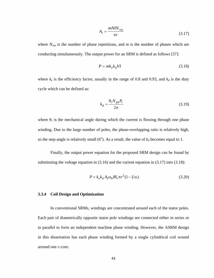
43
rmNIN
A reps π
= (3.17)
where Nrep is the number of phase repetitions, and m is the number of phases which are
conducting simultaneously. The output power for an SRM is defined as follows [37]:
VIkmkP de= (3.18)
where ke is the efficiency factor, usually in the range of 0.8 and 0.93, and kd is the duty
cycle which can be defined as:
π
θ=
2rphi
dPN
k (3.19)
where θi is the mechanical angle during which the current is flowing through one phase
winding. Due to the large number of poles, the phase-overlapping ratio is relatively high,
so the step-angle is relatively small (6o). As a result, the value of kd becomes equal to 1.
Finally, the output power equation for the proposed SRM design can be found by
substituting the voltage equation in (3.16) and the current equation in (3.17) into (3.18):
).11(2 a−πω= rBlAkkP rbsde (3.20)
3.3.4 Coil Design and Optimization
In conventional SRMs, windings are concentrated around each of the stator poles.
Each pair of diametrically opposite stator pole windings are connected either in series or
in parallel to form an independent machine phase winding. However, the ASRM design
in this dissertation has each phase winding formed by a single cylindrical coil wound
around one c-core.

44
The targeted power rating of the machine dictates the required magnetomotive
force to saturate the magnetic circuit. Therefore, the winding in an SRM, as the current-
carrying component, serves to produce the required flux density in the air-gap. One main
challenge winding designers face, is how to create enough volume within the stator core
in order to accommodate the winding coils.
The winding design objective is to achieve a certain level of flux density at the air-
gap with minimal copper and iron losses. The parameters that play a role in the coil design
can be confined to winding slot space, number of turns, coil dimensions, switching
frequency, skin effect, maximum permissible current density, insulation and the cooling
methods to be used. Most of these parameters have been well documented in literature for
the conventional radial-flux SRM. In this work the analysis will mainly focus on the
parameters that are important from the perspective of the proposed motor design.
3.3.4.1 Determination of a Single C-core Coil Inductances
The accurate calculation of aligned and unaligned inductances has always been an
essential step in the SRM design process, as it can predict the output power and
performance of the machine. Different methods have been adopted to analytically
calculate these parameters, such as the dual energy method [47] which is one of the
techniques used in finite element analysis. The proposed design in this dissertation has
the magnetic circuit (c-core and cube) for each phase separated from the other phases.
This particular feature offers multiple advantages, such as: 1) a reduction in the mutual
inductance between phases; and 2) a simplified design process. Due to this simplicity of
having individual and separated magnetic circuits, the inductances (aligned and
unaligned) of a single c-core coil can be derived by adapting the magnetic equivalent

45
circuit (MEC). The straightforward (MEC) lumped-parameter method is used here to
model a c-core along with two cubes in different positions, in an electrical network
representation. The flux tube technique is used to derive the reluctances in the air-gap
region. This approach has been used widely in electric machine analysis [48]-[50] and is
being incorporated here.
Assuming specific flux tube geometries depends to some extent on the skill and
care by which it is applied. And the observation of the flux distribution plot obtained by
FEM can provide considerable assistance [51]. Although FEA is considered the most
accurate method, it is still desirable to produce geometrical representation and analytical
formula, for inductances estimated by other techniques, as will be seen in the next
sections.
For flux tube of l as length, A as cross-sectional area, and µ as permeability, the
reluctance is given as:
dxxA
l
∫=ℜ0 )(
11µ
(3.21)
In Fig. 3-9, the flux lines are confined within specific paths or regions called flux
tubes. Their reluctances are functions of their geometrical dimensions and permeabilities.
Having the latter derived, the inductance can be found from the general expression in
(3.22):
total
NL ℜ=2
(3.22)

46
3.3.4.1.1 Inductance Derivation for the C-core Unaligned Position:
The unaligned inductance is considerably difficult to determine analytically
because of the complexity of the magnetic flux paths in the large air-gap. However, the
core material is not susceptible to saturation due to the large air-gap. The MEC is
developed with respect to the c-core geometric parameters. Fig. 3-10 shows the MEC
model for a single c-core and two cubes in a full unaligned position. Four main different
reluctances are observed. The appropriate flux tubes are proposed in order to calculate the
total reluctance of the magnetic circuit as follows:
1. The pole-to-pole reluctance (ℜpp): is derived using a rectangular cross-sectional area
through the large air gap as seen in Fig. 3-9. The integration in (3.21) is applied in
order to find the formula of this segment’s reluctance, as follows:
tr
pppp ll
g
0µ=ℜ (3.23)
where gpp is the pole-to-pole air-gap length, and lr and lt are the pole dimensions in the
radial and tangential directions respectively.

47
Fig. 3-9. The magnetic flux lines in the air-gap represented by flux tube. (a) For full aligned rotor
position. (b) For full unaligned position. ℜp1 and ℜp2 represent the reluctance of the two poles of
single c-core, ℜc-back is the back core reluctance, ℜc1 and ℜc2 represent the reluctance of the
corresponding cube.
Fig. 3-10. The magnetic circuit model for single c-core and two cubes in a full unaligned position.
2. The air-gap fringing reluctance (ℜf): the flux tube is approximated to be a semicircle
wedge. Fig. 3-9 shows two wedges in the 2-D plane. However, the 3-D effect is
Cube
mmf
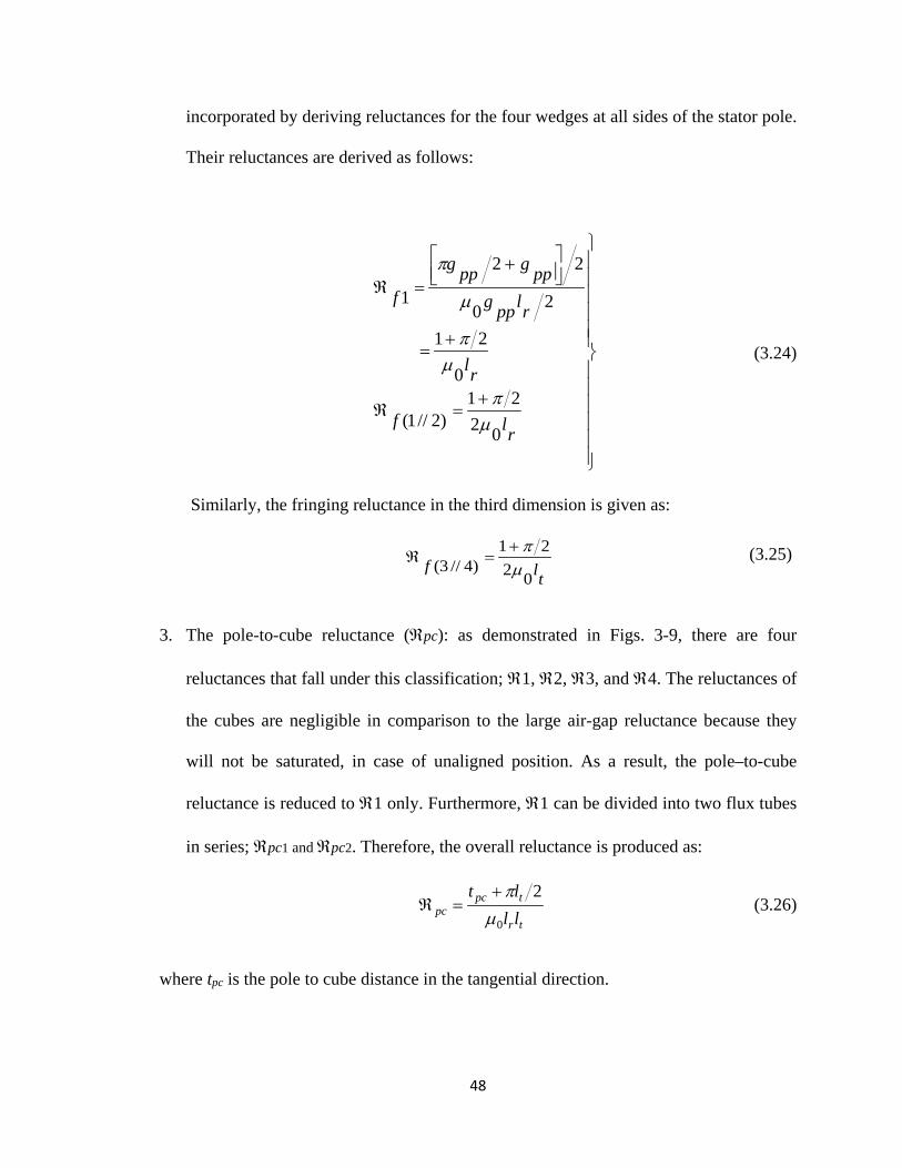
48
incorporated by deriving reluctances for the four wedges at all sides of the stator pole.
Their reluctances are derived as follows:
+=ℜ
+=
+
=ℜ
rlf
rl
rlppgppgppg
f
0221
)2//1(
0
21
20
22
1
µπ
µπ
µ
π
(3.24)
Similarly, the fringing reluctance in the third dimension is given as:
tlf
0221
)4//3( µπ+
=ℜ (3.25)
3. The pole-to-cube reluctance (ℜpc): as demonstrated in Figs. 3-9, there are four
reluctances that fall under this classification; ℜ1, ℜ2, ℜ3, and ℜ4. The reluctances of
the cubes are negligible in comparison to the large air-gap reluctance because they
will not be saturated, in case of unaligned position. As a result, the pole–to-cube
reluctance is reduced to ℜ1 only. Furthermore, ℜ1 can be divided into two flux tubes
in series; ℜpc1 and ℜpc2. Therefore, the overall reluctance is produced as:
tr
tpcpc ll
lt
0
2µ
π+=ℜ (3.26)
where tpc is the pole to cube distance in the tangential direction.

49
4. The leakage flux reluctance (ℜl): as the reluctance of the winding slot region, ℜl has
a significant share of the total reluctance. Moreover, this design has greater flux
leakage, due to the fact that the winding is less surrounded by steel than in radial flux
machines. Taking the coil cross section, Ac, as the flux tube cross section, and the coil
length, lc, as the flux path length, the leakage flux reluctance can then be given as:
cc
l Al
0µ=ℜ (3.27)
Having defined all the reluctances in the MEC, and by neglecting the core
reluctances, the equivalent reluctance in the case of an unaligned position is reduced to the
latter four main reluctances in parallel. Thus, the total reluctance is calculated
accordingly and then substituted in (3.22) to give the unaligned inductance as follows:
( )( )( ) ( ) ( )[ ]
( )( )[ ]tpcppc
ctlctpppcpp
pptpcctr
u ltgl
Allllgtg
gltlllN
Lππ
ππ
ππµ
++
+++++
+++
=22
242
2220
2
(3.28)
3.3.4.1.2 Inductance Derivation for the C-core Aligned Position:
For the fully aligned position, the task is relatively easier because only two types
of flux tubes are present. At the rated current, the magnetic circuit is saturated. So, the B-
H curve for the core material is utilized to obtain its permeability. The inductance at full
alignment with the fringing effect is accordingly developed as follows:
µπ
+µ
µπ
⋅µ
+µ
=
rg
a
rg
a
c
ca
lAg
lAg
Al
NL
0000
2
22
(3.29)
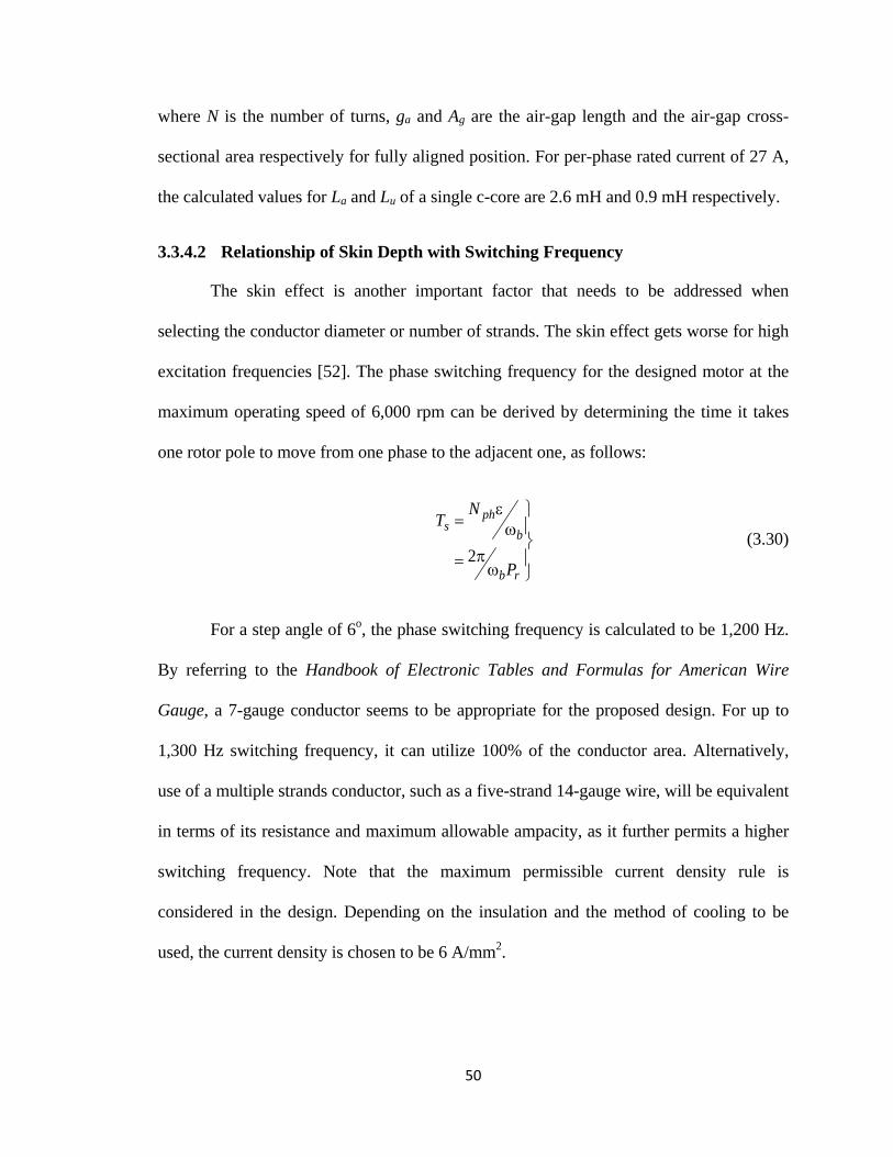
50
where N is the number of turns, ga and Ag are the air-gap length and the air-gap cross-
sectional area respectively for fully aligned position. For per-phase rated current of 27 A,
the calculated values for La and Lu of a single c-core are 2.6 mH and 0.9 mH respectively.
3.3.4.2 Relationship of Skin Depth with Switching Frequency
The skin effect is another important factor that needs to be addressed when
selecting the conductor diameter or number of strands. The skin effect gets worse for high
excitation frequencies [52]. The phase switching frequency for the designed motor at the
maximum operating speed of 6,000 rpm can be derived by determining the time it takes
one rotor pole to move from one phase to the adjacent one, as follows:
ωπ=
ωε
=
rb
bph
s
P
NT
2 (3.30)
For a step angle of 6o, the phase switching frequency is calculated to be 1,200 Hz.
By referring to the Handbook of Electronic Tables and Formulas for American Wire
Gauge, a 7-gauge conductor seems to be appropriate for the proposed design. For up to
1,300 Hz switching frequency, it can utilize 100% of the conductor area. Alternatively,
use of a multiple strands conductor, such as a five-strand 14-gauge wire, will be equivalent
in terms of its resistance and maximum allowable ampacity, as it further permits a higher
switching frequency. Note that the maximum permissible current density rule is
considered in the design. Depending on the insulation and the method of cooling to be
used, the current density is chosen to be 6 A/mm2.
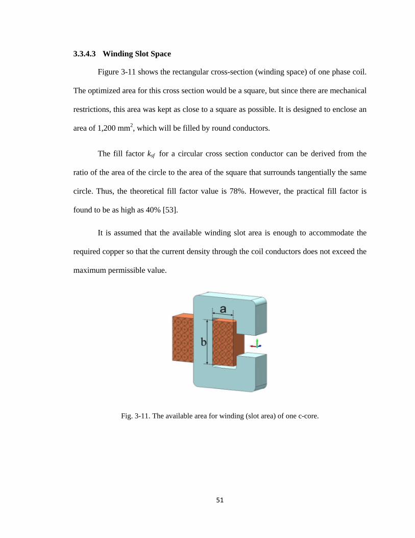
51
3.3.4.3 Winding Slot Space
Figure 3-11 shows the rectangular cross-section (winding space) of one phase coil.
The optimized area for this cross section would be a square, but since there are mechanical
restrictions, this area was kept as close to a square as possible. It is designed to enclose an
area of 1,200 mm2, which will be filled by round conductors.
The fill factor ksf for a circular cross section conductor can be derived from the
ratio of the area of the circle to the area of the square that surrounds tangentially the same
circle. Thus, the theoretical fill factor value is 78%. However, the practical fill factor is
found to be as high as 40% [53].
It is assumed that the available winding slot area is enough to accommodate the
required copper so that the current density through the coil conductors does not exceed the
maximum permissible value.
Fig. 3-11. The available area for winding (slot area) of one c-core.

52
A flow chart describing the complete process of the coil optimization is presented
in Fig. 3-12. In the first stage, the design objective is to find the minimum number of turns
at which the per coil current does not exceed Imax.
In the second stage, the number of turns is determined so that the back-EMF
equals the supply voltage at the base speed.
The third stage determines the number of strands so that for the maximum
switching frequency, 100% skin depth of each conductor is utilized.
Multiple 3-D FEA models of the c-core are built each with a different number of
turns while keeping the same supply voltage of 140 V. The calculation was performed for
a fixed speed of 2,400 rpm. The results in Fig. 4-1 demonstrate the inverse relationship
between the number of turns and both of the current and back-EMF, and verify the first
and second stages of the flow chart.

53
Fig. 3-12. Stages of coil design optimization.
No
Store Nst
Store N, I, Vs
Motor power rating, c-core dimensions and material determine the required magnetmotive force F. Assume
initial values for Vsi, Imax, ωb.
Number of turns per coil, N=0
N=N+1
Calculate the per coil current, I=F/N
I<Imax
e<Vs
e>Vs
Find the back-EMF,
Vs=Vs+1
,
Obtain fmax for the conductor of Aw cross-sectional area
fs<fmax
Nst=Nst+1
Yes
No
No
No
No
Yes
Yes
Yes
Yes
Round e up
Initial number of strands, Nst=1
(e-Vs)<1
Det
erm
ine
N fo
r Im
ax
Det
erm
ine
N a
nd V
s for
bac
k-EM
F D
eter
min
e N
st fo
r fs

54
Fig. 3-13.he current through one c-core coil obtained by 3-D FEA models at fixed speed
of 2,400 rpm, and for different number of turns.
0
10
20
30
40
50
0 0.2 0.4 0.6 0.8
Cur
rent
[A]
Time [ms]
50 Turns 60 Turns
70 Turns 80 Turns

55
Chapter 4
4. FINITE ELEMENT MODELS AND ANALYSES OF THE
DESIGNED AXIAL FLUX SRM
4.1 Optimal design and static 2D/3D analysis of the proposed ASRM
Although axial field motors require 3-D FEA modeling, a conversion method was
developed previously by the authors [54], to model the new design in 2-D. When
modeling in 2-D, there are some effects that should be considered in order to obtain a
model that signifies the real performance of the machine. Different correction
methodologies have been presented in literature to compensate the effects that 2-D
modeling cannot take into account. The common idea is to use empirical correction
factors [55], [56]. If the machine has a conventional design, the empirical factors may be
quite well known; hence, having a 2-D FEA is sufficiently accurate. Conversely in the
case of new motor design concepts, there is a considerable need for accurately
determining the effect of the geometry changes and saturation on motor efficiency and
other parameters related to the magnetic field.
For this study, the end winding effect and radial flux fringing constitute a
considerable portion among the other effects, as will be seen later in this chapter.

56
4.1.1 Development Process of the 3-D Machine Model
The SRM under investigation features a set of isolated magnetic circuits; each
represented by a c-core and one cube.
Due to this feature, along with the symmetry in the 3-D model, only one c-core
with one rotor cube is enough to generate the entire machine’s characteristics over the
range from the unaligned to the fully aligned position.
The 3-D model is analyzed employing the MagNet version 7 2-D/3-D
electromagnetic field simulation software from Infolytica Corporation. Fig.4-1(a) shows
the 3-D model of the c-core wound by one phase coil, and a slice of the rotor disc
carrying one rotor pole. It was built by sweeping the base lamination of the c-core with
the same dimensions of that for the 2-D model. The material used is the non-oriented
silicon steel (M19-29 gauge). The 3-D simulation process consumes significant
computational time; therefore, special care should be taken when assigning the mesh to
the model. Maximum element size (MES) is the tool used to refine the mesh only in
particular areas such as the air-gap and poles. The 3-D motion models with transient
analysis further increases the computational time cost. In order to reduce the model size
and address the computational time concerns, a horizontal (XZ) plane is used to divide
the c-core model into two symmetric halves, upper and lower parts, and then eliminate
the lower one keeping only the smallest portion required for 3-D modeling. The fields
will be everywhere normal to the symmetry plane; therefore, a field normal boundary
condition must be assigned to this plane. In order to validate the latter process, both

57
(a) (b)
Fig. 4-1. 3-D model. (a) One c-core wound by a phase coil and a slice rotor disc enclosing the
rotor cube. (b) 3-D model solution for the flux density for 75 A at 62% alignment.
complete and half c-core models were built and simulated under similar conditions and
the results confirmed that they are exactly equivalent.
The coil of the model is to be energized by ideal flat-topped current over the
whole stroke range. Fig. 4-1(b) presents the arrow and shaded plot for the flux density
solution when the excitation current is 75 A and number of turns is 40 at 62% alignment.
It clearly shows that the model can generate the needed MMF to saturate the areas of
interest.
The SRM magnetization characteristics and the single-coil output torque
calculated by the 2-D and 3-D models are presented in Figs. 4-2 and 4-3. The torque is
calculated according to: (τ=F×r), where F is the reluctance force obtained from the FEA
solution, and r is the distance between the rotor’s cube and the shaft. The noticeable
discrepancies between the 2-D and 3-D models solutions affirm the need for 3-D
modeling, especially at high excitation current levels.

58
Fig. 4-2. Comparison of the magnetizing characteristics of the proposed design at aligned and
unaligned positions by 2-D and 3-D FEA models (N=40).
Fig. 4-3. Shaft torque by single c-core at two different current excitations calculated by 2-D and 3-
D FEA models (N=40).
4.1.2 End Winding and Radial Flux Fringing in ASRM
In most conventional machines, the end winding portions usually constitute a
small fraction of the whole winding of one pole depending on the geometrical ratio of the
stator pole arc to the pole stack length, which usually ranges between the ratios 1:8 and
1:4. However, the c-core design at this stage has the ratio of 1:1”, due to the square cross-
0
0.01
0.02
0.03
0.04
0.05
0 15 30 45 60 75
Flux
-Lin
kage
[WB
.T]
Current [A]
3-D Aligned 2-D Aligned 3-D Unaligned 2-D Unaligned
0
4
8
12
16
20
0 1 2 3 4 5 6 7 8 9
Shaf
t Tor
que
[N.m
]
Rotor Position [degree]
2D-80A3D-80A2D-40A3D-40A

59
Fig. 4-4. End winding as part of the complete winding for square cross-sectional c-core.
section of its poles, as shown in Fig. 4-4. By referring to Fig. 4-2, the 3-D flux-linkage in
the unaligned position has approximately twice the value of that obtained from the 2-D
modeling. This is justified by realizing that the end winding portions are out of the 2-D
model and it can only be modeled by the 3-D one.
4.1.3 C-core Geometrical Modifications for Diverting the Fringing Flux
The fringing flux at the four edges of one pole tooth can be divided into two sets;
one of which is desired (tangential fringing flux), and can be seen on the side surface (S)
of the c-core, as shown in Fig. 4-5(a). This flux will result in additional force in the
tangential direction (the direction of the rotor motion). The other set of fringing flux can
be seen on the front side (F) of the c-core. This set does not contribute to the tangential
force. Instead, it will be deducted from the MMF causing a significant reduction in the
output torque that is noticed in the 3-D results in Fig. 4-3. This flux is known as the radial
fringing flux.

60
Various modifications on pole shapes were analyzed in an effort to reduce the
radial flux fringing and, alternatively, divert it to be with the tangential fringing flux.
Firstly, the improved pole shape, as shown in Fig. 4-6(a), is designed to minimize the
radial fringing. A wedge shape is created on the edge of the front side (F), while the (S)
side is kept flat. Furthermore, this design is modified to obtain the superior design by
making the cross-section of the pole a rectangle instead of a square, in which the length of
the rectangle is the side where the fringing flux is desired, as shown in Fig. 4-6(b). The
analysis of the gain obtained from these changes is explained in the magnified drawing in
Fig. 4-5(b). As we compare this modified shape with the original one, in Fig. 4-5(b)
and Fig. 4-5(c) respectively, it can be concluded that the fringing flux in the modified
shape would experience a longer path (more than the semi-circle that is in the original
shape) and consequently have a higher reluctance. The equation that relates to the
magnetomotive force and the reluctance is given by:
ℜφ== NIF
. (4.1)
It can be observed from (4.1) that for a given value of MMF, if the reluctance is
increased, the fringing flux will decrease which is in agreement with the FEA results. The
improvement in the magnetization characteristics, as shown in Fig. 4-7, is significant in
the aligned position where the saturation and fringing occur. This proves that the
modifications have achieved the goal of reducing the undesired fringing (radial fringing
flux). The improvements can also be seen in the comparison of the output torque for the
original, improved and superior models, as depicted in Fig. 4-8.

61
(a) (b) (c)
Fig. 4-5. The proposed pole shape modification. (a) 3-D model of the c-core showing the flux
fringing on the the front and side surfaces. (b) The close-up of modified shape shows longer flux
path. (c) The close-up of original shape shows shorter flux path.
(a) (b)
Fig. 4-6. Modifications on the 3-D model. (a) The improved pole shape. (b) The superior design
with rectangular cross-section of the c-core.

62
4.2 Analysis of the Operation of the Proposed ASRM Employing 3-D
Dynamic FEA
For the design and development of SRMs and their drives, analysis and
simulation of their dynamic behavior are essential. The dynamic performance of an SRM
is described by the following equations:
θ=∂ω∂
ω=θ∂
−=∂ψ∂
JiT
t
dt
tRitvt
d ),(
)()(
(4.2)
where θ is the rotor angular position, ω is the angular speed, J is the moment of inertia,
and Td is the developed torque. As can be seen, the flux linkage ψ, θ and ι are governed
by a non-linear relationship due to the saturation in the magnetic circuit. Several non-
linear SRM models have been developed and presented in literature [57], [58]
Fig. 4-7. The magnetization characteristics for the original design, the improved pole shape
design, and the superior design (N=40).

63
Fig. 4-8. Shaft torque provided by single coil, calculated by 3-D FEA for the original pole
geometry, the improved and the superior designs for two different current values.
FEM is found to be the optimum solution as it provides a precise solution through
accurate computation of the magnetic field for a developed model. The switched
reluctance motor operates in a series of strokes or transients and does not have steady
state in which all its variables are constant. Therefore, it is reasonable to evaluate its
dynamic operation by looking at individual strokes through 3-D FEA simulation. Here, 3-
D FEA based motion model is employed at discrete speeds chosen from low, moderate
and high speed regions in order to investigate the dynamic performance over the full
speed range operation. This has been performed owing to the extremely large time
consumption of 3-D FEA over the entire speed region.
It should be noted that the calculations, results and analyses presented are based
on a single-coil computation. This is reasonable due to the complete separation of any c-
core magnetic circuit from the other c-cores. The mutual inductances between adjacent
phases or coils are negligible due to the sufficient spacing between them. The electric
0
3
6
9
12
15
18
21
0 1 2 3 4 5 6 7 8 9
Shaf
t Tor
que
[N.m
]
Rotor Position [degree]
Superior Design @ 80AImproved Design @ 80AOriginal Design @ 80ASuperior Design @ 40AImproved Design @ 40AOriginal Design @ 40A

64
excitation is provided to the c-core winding through single phase asymmetric bridge
converter, as in Fig. 4-9 and is linked to the FEA model. The operation is divided into low
speed region and high speed region. This separation is based on the method of control
that needs to be applied to the motor.
4.2.1 Low Speed Range Operation
When the two power switches in Fig. 4-9 turn on, the full DC bus voltage is
applied across the phase coil and the single phase voltage equation will govern the
voltage, current and back-EMF as follows
eRiV += (4.3)
where e is the back-EMF which is also defined as
θ∂ψ∂ω=
∂ψ∂=
m
te (4.4)
Accordingly, at low speeds, the back-EMF is small and most of the bus voltage appears
in the first term of the right-hand side of (4.3). In other words, there will be
Fig. 4-9. Single phase asymmetric bridge converter is linked to the 3-D FEA model to energize
one c-core coil.
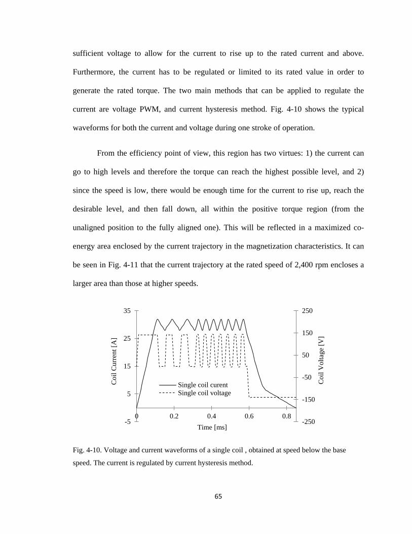
65
sufficient voltage to allow for the current to rise up to the rated current and above.
Furthermore, the current has to be regulated or limited to its rated value in order to
generate the rated torque. The two main methods that can be applied to regulate the
current are voltage PWM, and current hysteresis method. Fig. 4-10 shows the typical
waveforms for both the current and voltage during one stroke of operation.
From the efficiency point of view, this region has two virtues: 1) the current can
go to high levels and therefore the torque can reach the highest possible level, and 2)
since the speed is low, there would be enough time for the current to rise up, reach the
desirable level, and then fall down, all within the positive torque region (from the
unaligned position to the fully aligned one). This will be reflected in a maximized co-
energy area enclosed by the current trajectory in the magnetization characteristics. It can
be seen in Fig. 4-11 that the current trajectory at the rated speed of 2,400 rpm encloses a
larger area than those at higher speeds.
Fig. 4-10. Voltage and current waveforms of a single coil , obtained at speed below the base
speed. The current is regulated by current hysteresis method.
-250
-150
-50
50
150
250
-5
5
15
25
35
0 0.2 0.4 0.6 0.8
Coi
l Cur
rent
[A]
Time [ms]
Coi
l Vol
tage
[V]
Single coil curentSingle coil voltage
66
4.2.2 Rated and High Speed Range Operation
Above the base speed, the back-EMF is increased until it becomes higher than the
DC supply voltage, thus eliminating the need to limit the current. On the contrary, one
needs to advance the switching in order to allow the current to reach its rated value before
being limited by the back-EMF that tends to increase significantly with the increase in the
overlapping area between the poles. Fig. 4-12 shows the current traces for different
speeds obtained by advancing the firing angle for increasing the speed as shown in Table
4-1. Although the current is inherently limited, in the case of rated and high speed
operations, it exponentially increases for speeds lower than the rated value, thus requiring
a precise current regulation.
Fig. 4-11. The flux linkage trajectories against current obtained by 3-D FEA models under
transient (motion) analysis, for three different speeds.
0
0.005
0.01
0.015
0.02
0.025
0.03
0.035
0 5 10 15 20 25 30
Flux
Lin
kage
[Wb.
T]
Current [A]
2,400 rpm
3,000 rpm
3,600 rpm

67
Table 4-1. Firing Angle Look-up Table for Low and High Speed Ranges.
Speed (rpm) 1,200 1,800 2,400 3,000 3,600 4,200
Turn on (mm) -24 -27 -30 -33 -35 -38
Turn off (mm) -6 -10 -12 -13 -14 -14
Fig. 4-12. Set of current traces obtained by varying the firing angle positions in accordance with
different motor speeds.
4.3 Motor Performance Characteristics
The output torque observed at the shaft while running at rated speed for three
consecutive phases is simulated in the 3-D motion model and the results are shown in
Fig. 4-13. Based on the standard definition of torque ripple as in (3.1), the observed
motor torque ripple is approximately 15% which is considered sufficient results, since no
control technique has been used, whereas the current can be boosted in regions of low
torque. With basic conventional control, this torque ripple can be brought to a negligible
value.
0
10
20
30
40
50
-35 -30 -25 -20 -15 -10 -5 0
Cur
rent
[A]
Position [mm]
1,200 rpm
1,800 rpm
2,400 rpm
3,000 rpm
3,600 rpm

68
The solution of the 3-D FEA model as shown in Fig. 4-14 provides the forces
along the three coordinate axes. The radial force corresponds to the X-axis and shows
negligible values. For the purpose of fair comparison with the radial SRM configuration,
one would have to consider comparing the axial force of the axial SRM versus the radial
force of the radial SRM. This comparison is provided in Fig. 4-15. Also, for proper
comparison, the three models are current driven with the same value, and the design
models are scaled in order to make all related parameters and dimensions identical, as
possible. The design parameters and dimensions, such as the axial and radial dimensions
and air-gap length, are identical and presented in Chapter 2. While the c-core model is
scaled to equivalent values like the other two models, as close as possible. It is noticeable
that the proposed ASRM has significantly lower axial forces (approximately 10 times
lower) compared to the radial forces in radial SRM, leading to lesser acoustic noise, thus
validating one of the intended purposes of the novel design.
Lastly, the ASRM ratings that were obtained by 3-D FEA simulation under
multiple speed operation are summarized in Table 5-1. The predicted dynamic
performance is described in the motor characteristics in Fig. 4-16.
Fig. 4-13. The output torque profile for three consecutive phases showing the individual
contribution from each phase.
-8
0
8
16
24
32
40
48
0.2 0.4 0.6 0.8 1 1.2 1.4 1.6
Torq
ue [N
.m]
Time [ms]
Shaft torque First phaseSecond phase Third phase

69
Fig. 4-14. 3-D FEA model solution for the purpose of obtaining forces along the X-Y-Z axes.
Due to the symmetry in the 3-D model, only one halve of the model is sufficient representation of
one complete c-core.
Fig. 4-15. Comparison of the radial forces of the in-wheel radial SRM, the convential radial
SRM, and the axial force of the axial SRM.
-500
500
1500
2500
3500
4500
5500
0 5 10 15 20 25
Rad
ial f
orce
[N]
Rotor mechanical angle [Degree]
ASRM
In-wheel SRM
Conventional SRM

70
Fig. 4-16. The ASRM power and torque-speed characteristics.
0
2,000
4,000
6,000
8,000
10,000
0
10
20
30
40
0 900 1800 2700 3600 4500
Pow
er [W
]
Shaf
t Tor
que
[N.m
]
Motor Speed [rpm]
TorquePower

71
Chapter 5
5. ASRM PROTOTYPE DEVELOPMENT AND TESTING
5.1 Development of the ASRM Prototype
Prior to the prototype hardware implementation, several design optimization and
improvement stages have been completed. Comprehensive static and dynamic analyses in
2-D and 3-D environments have been performed. From a construction point of view, the
motor prototype consists of the following components:
1. The c-cores and the cubes: In accordance with the c-core superior design model in Fig.
4-6(b), a prototype that has the same dimensions with minor modifications is built and
shown in Figs. 5-1 and 5-2. Fully processed non-oriented silicon steel laminations,
M19-29, are used. The laminations are stacked together in the z-axis (tangential
direction). In order to keep the thin laminations together and to suppress any
harmonic-base vibration among the steel sheets themselves, several laser welding
locations are distributed evenly around the volume of the c-core as shown in Fig. 5-
2(b). Evidently, there is no welding on the internal edges of the c-core due to
manufacturing capability constraints. However, the welding distribution on the outer
sides has achieved the desired mechanical strength. It should also be noted that the
welding locations were chosen to be as far as possible from the regions of high flux
density, which can be seen in the FEA-flux density solution in Fig. 5-1(a).

72
(a) (b)
Fig. 5-1. C-core development. (a) Final version of the 3-D FEA model showing the shaded plot of
the magnetic flux density of single c-core at full alignment. (b) The corresponding prototype
during winding process.
(a) (b)
Fig. 5-2. Prototype core components. (a) Proposed c-cores arrangement of the novel ASRM
design. (b) An individual c-core with dimensions. Welding locations are marked by arrows.

73
2. The winding coils: This design has five phases, three repetitions, and concentrated
winding around each of the 15 c-cores. The number of turns, strands, and conductor
diameter has been determined according to the coil design algorithm that was
explained previously in chapter 3, and based on the current constraint and voltage
source availability N is found to be 60. The actual measured area of the cross-section
of the coil is found to be 1,227 mm2 which results in a high practical winding fill
factor of 40.9%. This is due to the special geometric shape that allows for individual
winding of each coil prior to its final assembly into the housing of the motor. Figures
5-1 and 5-6(a) demonstrate the availability of large room for extra winding around the
c-core which will reduce the copper loss in the machine unlike other conventional
machines where the amount of winding is limited by the slot space. Copper loss is the
principle loss in SRM, and hence the overall efficiency can be optimized as efficiency
improvement remains a major bottleneck in electric vehicle drivetrain. The resistance
of the individual winding has been calculated depending on the conductor length and
area. Also, the actual resistance has been measured using a micro ohm meter and both
the calculated and measured results are provided in Table 5-1. Talking about the fault
tolerance capability, this machine can withstand any fault in the c-core winding since
the cores are wound individually, and hence will remain operational until the c-cores
are re-placed. These significant characteristics recommend the motor to top the list of
electric machines used in the drivetrain.
3. The rotor, which has a disc shape, is built using aluminum material (Al 6061-60T).
The slot in the aluminum rotor disc was designed to be a bit larger than the length of

74
the cube. Once the cube was inserted into the slot, it was pushed towards the
circumference of the disc and firmly fixed by the two locks as shown in Fig 5-3.
Table 5-1. RATINGS OF THE PROPOSED ASRM.
Output power 9 kW Base speed 2,400 rpm
DC voltage 140 V Maximum speed 5,500 rpm
Rated current 80 A Maximum torque 56 N.m
Rated torque 37 N.m Maximum power 14 kW
Calculated single coil resistance 29.6 mΩ Measured single coil
resistance 31 mΩ
(a)
(b)
Fig. 5-3. Rotor construction and assembly. (a) Isometric view of the final assembly. (b) The cross-
section view of the rotor disc
Rotor cube
Rotor
Locks
C-core
Shaft
Rotor cube
Rotor disc

75
In order to ensure safe operation at high speeds, a mechanical strength study is
essential for the body of this disc at the critical regions, specifically at the
circumference, outward of the rotor cube as shown in Fig. 5-4. The study objective is
to verify that the direct shear stress τ, at A, which is caused by the centrifugal force of
the rotor cube during high speed operation, does not exceed the Ultimate Shear
Strength (Ssu) of the aluminum material. The direct shear stress is given by:
AF
2=τ (5.1)
where A=ht. The “2” in the denominator indicates the double shear that exists. The
centrifugal force at the cube centre relates the cube mass, angular speed, and rotor
radius as follows:
F=mw2r . (5.2)
The calculation results show that for the specific dimensions and for speeds up to
6,000 rpm, the direct shear was (31.8 MPa) which is significantly below the ultimate
shear strength of (207 MPa).
4. The housing is built from the same aluminum material that was used in constructing
the rotor disc. The slots provided by the housing sides and segments restrain the c-
Fig. 5-4. The area of high shear stress in the rotor disc.
A

76
cores from delocalization in the tangential axis against any type of vibration.
Additional moveable locking wedges are designed to prevent delocalization in the
radial axis and to allow for quick and easy replacement of any c-core in case of a
damaged coil. Two pairs of tapered roller bearings are used to accommodate the axial
thrust in either direction, as well as the radial loads. This design allows the motor to
maintain a constant air-gap in spite of vehicular vibrations.
The Mechanical CAD drawing showing all components of the motor is presented in
Fig. 5-5. The final motor assembly is shown in Fig. 5-6(a). In the present work, the
prototype has been subjected to static testing in order to measure the magnetizing
characteristics, machine parameters and to verify the correctness of the design.
5.2 Experimental Determination of the Static ψ-i Characteristics of the
Developed Prototype
The magnetization characteristics are considered as the fingerprints of SRMs as they
provide the essential information required to predict the behavior of these machines.
Thus, we obtained these characteristics experimentally by holding the rotor at the two
extreme positions; the aligned and unaligned ones. An indirect method, as in [59], is used
for this purpose. The experimental setup is shown in Fig. 5-6(b). An isolated channels
oscilloscope records the voltage and current data over the time frame that begins at the
instant of applying voltage across the winding and terminates once the current reaches
steady state. These data is transferred to a PC where it will be employed in performing the
integration as follows:

77
(a) (b)
Fig. 5-5. The Mechanical CAD drawing of the assembled prototype (dimensions are in mm). (a)
Side view. (b) Front view.
(a) (b)
Fig. 5-6. Prototype development. (a) Final assembly showing one c-core removed. (b)
Experimental setup for obtaining the magnetization characteristics.
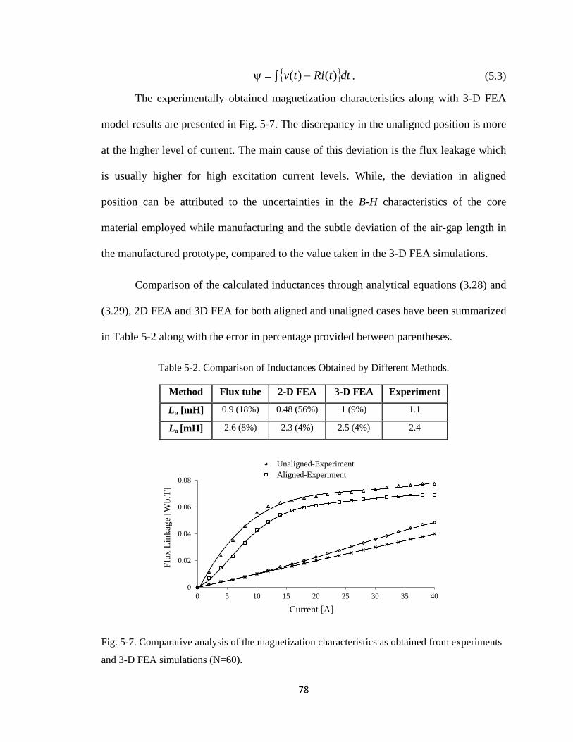
78
dttRitv∫ −=ψ )()( . (5.3)
The experimentally obtained magnetization characteristics along with 3-D FEA
model results are presented in Fig. 5-7. The discrepancy in the unaligned position is more
at the higher level of current. The main cause of this deviation is the flux leakage which
is usually higher for high excitation current levels. While, the deviation in aligned
position can be attributed to the uncertainties in the B-H characteristics of the core
material employed while manufacturing and the subtle deviation of the air-gap length in
the manufactured prototype, compared to the value taken in the 3-D FEA simulations.
Comparison of the calculated inductances through analytical equations (3.28) and
(3.29), 2D FEA and 3D FEA for both aligned and unaligned cases have been summarized
in Table 5-2 along with the error in percentage provided between parentheses.
Table 5-2. Comparison of Inductances Obtained by Different Methods.
Method Flux tube 2-D FEA 3-D FEA Experiment
Lu [mH] 0.9 (18%) 0.48 (56%) 1 (9%) 1.1
La [mH] 2.6 (8%) 2.3 (4%) 2.5 (4%) 2.4
Fig. 5-7. Comparative analysis of the magnetization characteristics as obtained from experiments
and 3-D FEA simulations (N=60).
0
0.02
0.04
0.06
0.08
0 5 10 15 20 25 30 35 40
Unaligned-ExperimentAligned-Experiment
Flux
Lin
kage
[Wb.
T]
Current [A]

79
5.3 Heat Run Test Performed on the Designed Prototype
The objective behind this test is to verify that at the rated power loss, the
temperature rise of the machine is within limit, as dictated by the class of insulating
materials used. No standard procedures for heat run test on an SRM exist at present, to
the best knowledge of the authors. In order to perform the heat run test on an electrical
machine in general, the rated voltage is applied and the machine is loaded to ensure rated
current. This ensures the rated loss (core plus copper losses) to occur inside the machine
on a continuous basis and the temperature rise at steady state is noted or calculated.
Borrowing this idea, since the drive for this prototype is still in the process of being
developed, a DC voltage source has been used to supply a continuous DC current through
the winding that is higher than the rated current by about 25%. This additional amount of
current has been deliberately passed on a continuous basis to take care of the heat that
would have been generated due to the iron loss at rated voltage and other stray losses. For
Fig. 5-8. Heat run test setup; deep-cycle lead-acid batteries supplying 40 A to the prototype
winding, thermometer is showing 45°C after 30 minutes.

80
Fig. 5-9. Experimentally-measured temperature rise of the prototype winding starting from the
ambient temperature, and recorded every minute till thermal equilibrium is reached. The excitation
current is 40 A.
this purpose, all the c-core coils are connected in series to a deep cycle battery, as shown
in Fig. 5-8. The steel cubes are removed to eliminate any undesired or harmful vibrations
during the long test process. A thermocouple is inserted near the surface of one coil, and
the temperature is recorded by a Fluke 89IV meter. Fig. 5-9 shows the experimental
temperature-time curve, wherefrom the steady state temperature has been found to be
about 47oC. The hot spot temperature of the winding is estimated to be 20°C higher than
the measured one. As the insulating materials used for building the prototype belonged to
Class B, the entire design is thus validated. The reserve thermal capacity of this design is
keeping in view the short time overloads that this SRM is expected to undergo under fast
acceleration/deceleration for an electric vehicle application.
18
24
30
36
42
48
0 8 16 24 32 40
Tem
pera
ture
[°C
]
Time [min.]

81
5.4 Experimental Torque/Current vs. Rotor Position Angle
Characteristics
Experiments were performed using the proposed ASRM coupled to a
programmable loading machine through a torque transducer. The ASRM was run at the
rated speed and the motor was tested by applying one pulse to a single coil. This test
serves as an initial step towards the drive development which is ongoing. The current was
limited by the back emf, since the machine was run at rated speed. The experimental
setup and the measured results of torque/current are shown in Figs. 5-10 and 5-11
respectively. It can be noticed from the figures that the current is plummeting down due
to the low inductance of the coils. Thus, the results are found to be satisfactory when
compared to that of the FEA.
Fig. 5-10. Experimental setup of the ASRM coupled to the loading machine.

82
Fig. 5-11. Experimentally-measured shaft torque and corresponding current provided by single
coil.
5.5 Conclusion
The motor prototype construction was explained in this chapter. A pair of tapered
roller bearings was necessary to accommodate the axial thrust in either direction, as well
as the radial loads. The thermal design testing showed steady state temperature of about
48°C. The hot spot temperature of the winding is estimated to be 20°C higher than the
measured one, hence class B insulating materials is used. Lastly, the experimental torque
measurement, contributed by only one c-core, comes in sufficient agreement with the
ASRM ratings that were obtained by 3-D FEA simulation under multiple speed
operation, since the FEA results was for the whole motor which energizes three c-cores
coils at a time (the motor has a repetition of three).
Rotor Position (deg.)
Torq
ue (N
m)
Cur
rent
(A)

83
Chapter 6
6. NOVEL APPROACHES TOWARDS LEAKAGE FLUX
REDUCTION IN AXIAL FLUX SWITCHED RELUCTANCE
MACHINES
The finite element analysis performed on the axial flux SRM in chapter 3 showed
discrepancy between its 2-D and 3-D results in the unaligned position. Experimental
investigations performed on the developed prototype have shown a relatively low
inductance ratio. Furthermore, it is verified that the unaligned inductance is high which
causes the low inductance ratio [60] that leads to a low torque to ampere ratio in axial
flux SRM. Hence, in this chapter, firstly, a flux tubing model along with a flux
distribution plot obtained by 3-D FEM was employed to analyze the factors that are
causing the poor inductance ratio. The above issues have been thoroughly studied and
three different approaches have been proposed in this chapter in order to reduce the
leakage flux and, therefore, improve the inductance ratio. One approach is related to
modification in winding, the second approach suggests the utilization of grain oriented
steel segments and the third one proposes a novel method for using permanent magnet
material as a shield to the leakage field. Each of these approaches are modeled and
analyzed in detail through 3-D FEA and the results are discussed.

84
6.1 Investigation of Leakage Flux in Axial Flux SRM through Flux
Tubing/Magnetic Equivalent Circuit
The torque producing capability of an SRM mainly depends on the rate of change
of the inductance vs. rotor position. An indicator for that is the inductance ratio La/Lu,
where La and Lu are the aligned and unaligned inductances respectively. The accurate
calculation of these inductances has always been an essential step in the SRM design
process. A lumped-parameter magnetic equivalent circuit (MEC) has been developed in
pervious sections, where the magnetic circuit is represented by a lumped parameter
electrical network. Since the motor under study has the magnetic circuit (c-core and cube)
for each phase separated from the other phases, the author would like to state that the
following investigation will only consider a single c-core along with a cube, as the rotor
pole.
The flux tube technique was used to derive the reluctances in the air-gap region.
Fig. 6-1 shows the MEC model for a single c-core and two cubes in a full unaligned
position. For the unaligned position case, and due to the large airgap, the c- core material
will not saturate, hence its reluctances can be neglected. ℜc-back = ℜp1 = ℜp2 = ℜc1 = ℜc2
= 0. While, all air gap reluctances are large, as always. As a result, the leakage reluctance
dominates in the unaligned position. On average, this leakage constitutes about 25% of
the total flux. This is also verified by 3-D FEA simulation [60]. Simulation for the same
c-core under exact conditions except the volume of the air box was repeated. The findings

85
Fig. 6-1. The magnetic circuit model for single c-core and two cubes in a full unaligned position.
prove that as the air box volume grows, the leakage flux increases, to a certain limit. This
validates our analysis, since most of the leakage occurs in the air surrounding the coil.
6.2 Proposed Leakage Flux Reduction Methods
6.2.1 Reduction through modified winding configuration
Taking the coil cross section, Ac, as the flux tube cross section, and the coil length,
lc, as the flux path length, as shown in Fig. 6-2(a), the leakage flux reluctance can then be
given as:
cc
l Al
0µ=ℜ (6.1)
From (6.1) it is observed that in order to increase the leakage reluctance, we should either
increase the length of the coil, reduce the coil cross section, or both. However, the first
option is limited by the length of the c-core itself. And the second option conflicts with
the desire to have more copper, so that higher current can be allowed through the
winding, and hence higher torque can be achieved. An optimized case is proposed and
mmf

86
(a) (b)
Fig. 6-2. A new winding method. (a) Coil dimensions. (b) Conventional winding wire vs. square
cross-section winding wire for optimum fill factor.
tested by using square single strand winding wire. As can be seen in Fig. 6-2(b), the
utilization of square cross-section magnetic wire significantly increases the winding fill
factor; consequently, cross- sectional area of the coil is reduced for the same amount of
copper, and hence, the leakage reluctance increases. Fig. 6-3 shows a test structure
constraining a c-core, with the coil cross section area smaller than that of the original coil
by 25%. The c-core magnetization characteristics are obtained experimentally by holding
the rotor cube at two extreme positions; the aligned and unaligned ones. The method used
in [59] is adopted here for this purpose. An isolated channels oscilloscope records the
voltage and current data over the time frame that begins at the instant of applying voltage
across the winding and terminates once the current reaches steady state. This data is
transferred to a PC where it will be employed in performing the integration as follows:
ttRitv ∂−=ψ ∫ )()( . (6.2)

87
Fig. 6-3. Test structure constraining a c-core with the coil cross section area smaller than that of
the original coil by 25%.
Fig. 6-4. Comparative analysis of the magnetization characteristics of a single c-core with special
winding configuration as obtained from experiments and 3-D FEA simulations.
The aligned and unaligned flux linkage is measured and the saturation
characteristic is provided in Fig. 6-4. The noticeable reduction of the unaligned flux
linkage validates this proposed method. This winding configuration seems to improve the
0
0.02
0.04
0.06
0.08
0 500 1000 1500 2000 2500
Flux
Lin
kage
[Wb.
T]
MMF [AT]
FEA-Aligned Experiment-Aligned
Experiment-Unaligned FEA-Unaligned

88
reduction in leakage flux by a factor of 5% when compared to the original winding
configuration.
6.2.2 Reduction through segmented grain oriented steel core
Another approach to minimize the leakage flux can be achieved by selecting the
core material that has some control on direction of flux lines inside it. Such material is
called Grain-Oriented (GO) electrical steel. In general, GO electrical steel has been
limited to transformers and high power rotating machines, while Non Grain-Oriented
(NGO) steel to rotating machines. That is because the GO steel is highly anisotropic; it
has an axis of easy magnetization and low power loss [001], coincided with the rolling
direction, and an axis of hard magnetization and high loss [111] [61].
The c-core can be divided into three segments as shown in Fig. 6-5. The middle
segment is particularly important for reducing the leakage flux. Its orientation along the
coil axis increases the core permeability along the same axis, and constrains the flux lines
in one direction. The other two segments are useful to curve the flux lines in the desired
Fig. 6-5. Orientations of the segmented grain oriented c-core used in the design.

89
direction. These segments’ configuration increases the overall permeability in the core
and hence reduces the losses. Also, it is particularly suitable for this topology of axial
SRM since its magnetic circuits are isolated from each other as explained before, and the
coil’s excitation current is always unidirectional. 3-D FEA results of a segmented c-core
model that was built using grain oriented silicon steel, Alphasil 35 M6, have showed
slight improvement in term of reducing leakage flux as well as improving the inductance
ratio, as can be seen in Fig. 6-9.
6.2.3 Inductance ratio improvement through novel shielding strategy using
permanent magnet material
The general definition of electromagnetic shielding revolves around the
techniques of reducing the electromagnetic field in a space by blocking the field with
barriers made of conductive or magnetic materials. Electromagnetic shielding has been
used in a very wide range of different applications. Their major function was either to
protect the devices or the human beings that are in proximity to a source of a magnetic
radiation. Three main techniques of shielding have been well documented in literature: 1)
passive shielding with high permeability materials or superconducting sheets [62]; 2)
active shielding with compensation coils which produce a cancelling field: and 3) a
combination of the above.
Electromagnetic shielding has rarely been used in electric machines. The Authors
in [63] have proposed active shielding for leakage flux reduction in a transformer where
the shielding is provided by two compensating coils being wound on the same core as for

90
the primary and secondary coils, but no work has been done to study the effects of
electromagnetic shielding in electric motors.
As the leakage magnetic fields contribute to several undesirable effects in many
applications [64], and more specifically in axial flux SRM [60], there is considerable
interest in reducing such fields [65]. In this section the author proposes a novel concept in
which permanent magnet material is used to provide a field that opposes the leakage
fields, and hence reduces the leakage flux significantly. Although the concept is being
proposed here for reducing the leakage flux in SRM, the concept can be applied in
different kinds of machines wherever it is feasibly justified.
By referring to the flux tubing model and the MEC in Fig. 6-1, it can be deduced
that in order to reduce the leakage flux, the branch that has ℜl should contain a
magnetomotive force (mmf) in the opposite direction to that of the original mmf
generated by the coil, so that the flux in that branch becomes zero. The FEA field
solution in Fig. 6-8(a) shows that most of leakage occurs near the two ends of the coil,
and that any leakage from the side of the coil can be neglected. Therefore, it is suggested
to design the leakage shield at these two ends. Two permanent magnets (PMs) are
designed to suppress the leakage flux at both ends of a c-core coil as shown in Fig. 6-
8(b).
These magnetic shields should be capable of at least producing equivalent
magnetic field to the leakage field, and in the opposite direction. These magnets were
initially designed depending on the estimated value of the leakage field by using the
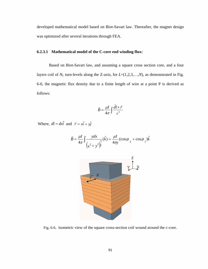
91
developed mathematical model based on Biot-Savart law. Thereafter, the magnet design
was optimized after several iterations through FEA.
6.2.3.1 Mathematical model of the C-core end winding flux:
Based on Biot-Savart law, and assuming a square cross section core, and a four
layers coil of NL turn-levels along the Z-axis, for L=(1,2,3,…,N), as demonstrated in Fig.
6-6, the magnetic flux density due to a finite length of wire at a point P is derived as
follows:
∫×
=r
rldIB34
πµ
Where, idxdl ˆ= and jyixr ˆˆ +=
( )k
yIk
yx
ydxIB ˆ)cos(cos4
)ˆ(4 12
22 23 θθ
πµ
πµ
+=
+
= ∫
Fig. 6-6. Isometric view of the square cross-section coil wound around the c-core.

92
Fig. 6-7. Top view of the coil end of a square cross-section c-core showing four layers.
In order to calculate the magnetic flux due to four layers, the defined angles θn(1) and θn(2) for n=(1,2,3,4) and the displacement vector ( r ) are incorporated according to Fig. 6-7.
For layer 1:
kyIB N
ˆ)cos(cos4 )2(1)1(1),1(1 1 θθπµ
+=
)ˆ)(cos(cos)(4
')2(1
')1(1),2(1 1
kay
IB N −++
= θθπ
µ

93
Due to the placement of the magnetic core, the flux density from the far side of
coil is negligible
The flux from sides 3 and 4 cancel each other: ),4(1 1NB
0),3(1 1 =+ NB
Similar analysis can be applied to layer 2, 3, and 4, resulting in the following,
)ˆ)(cos(cos)4(4 )2(2)1(2),1(2 1
kyIB N −+−
= θθπ
µ
)ˆ)(cos(cos)8(4 )2(3)1(3),1(3 1
ky
IB N −+−
= θθπ
µ
ky
IB Nˆ)cos(cos
)12(4 )2(4)1(4),1(4 1 θθπ
µ+
−=
,
=−− 1)( NPatTotalB
)1,1(4)1,1(3)1,1(2)1,1(1 NNNN BBBB
+++
For the levels of turns N2, N3 . . . NN, the magnetic flux will have a component
along X and Z axis, as can be seen in Fig. 6-6, and the displacement vector ( r ) and
magnetic flux calculation for second level-turn and first layer will be as follows,
idxdl ˆ=
kzjyixr Nˆˆˆ
22 ++=
( )
)ˆ))((cos(arctan)n((cos(arcta
ˆ))(cos(arctan)n((cos(arcta
)ˆ)((ˆ)(44
2
222
1
222
222
2
2
222
1
222
222
2222 2
32
3),1(1 2
ix
zyx
zyzy
z
kx
zyx
zyzy
y
zyx
idxzkydxIr
rldIB
NN
N
N
NN
N
N
NN
−+
++
+
++
++
+
=++
−+=
×= ∫∫ π
µπ
µ
Similar procedures are followed for the second level-turn and second layer:

94
( )
)ˆ))()4(
(cos(arctan))4(
n((cos(arcta)4(
ˆ)))4(
(cos(arctan))4(
n((cos(arcta)4(
)4(
)4(
)ˆ)((ˆ))4((44
2
222
1
222
222
2
2
222
1
222
222
2222 2
32
3),1(2 2
ix
zyx
zyzy
z
kx
zyx
zyzy
y
zyx
idxzkdxyIr
rldIB
NN
N
N
NN
N
N
NN
−+−
++−
+−
++−
++−
+−−
=+−+
−+−=
×= ∫∫ π
µπ
µ
Similarly for second level-turn and third layer:
( )
)ˆ))()8(
(cos(arctan))8(
n((cos(arcta)8(
)ˆ))()8(
(cos(arctan))8(
n((cos(arcta)8(
)8(
)8(
)ˆ)((ˆ))8((44
2
222
1
222
222
2
2
222
1
222
222
2222 2
32
3),1(3 2
ix
zyx
zyzy
z
kx
zyx
zyzy
y
zyx
idxzkdxyIr
rldIB
NN
N
N
NN
N
N
NN
−+−
++−
+−
+−+−
++−
+−−
=+−+
−+−=
×= ∫∫ π
µπ
µ
For different number of level-turns, the Z axis component will be replaced in above
equations. And displacement vectors for all turns will be as follow:
kzjyixr Nˆˆˆ
22 ++=
kzjyixr Nˆˆˆ
33 ++=
kzjyixr Nˆˆˆ
44 ++=
.
.
. kzjyixr NNNˆˆˆ ++=
And, the total magnetic flux at point P will be calculated as follows:
.1
),1(4),1(3),1(2),1(11
)int()int( ∑ +++=∑===
−−−−−−N
iNiNiNiNi
N
iNippoatTotalppoatTotal BBBBBB

95
The analytical approach along with the flux tubing model provides the
preliminary value of the leakage field that needs to be suppressed by the magnets, as a
shield. The end results of a design procedure for any PM are selecting the suitable
magnetic material and dimensions of the magnets. The rule of thumb is that the magnetic
material should tolerate the maximum flux density without losing its magnetism. To
ensure proper selection, the operating point on the material demagnetizing curve should
be studied. Since the magnets are located in a low permeability media (air), therefore, the
magnet is operating at a flux below the remnant flux φr, as the mmf drop across the large
airgap is seen by the magnet as negative demagnetizing mmf. Additional demagnetizing
mmf is affecting the magnet which is caused by the leakage field from the c-core. This
addition drives the operating point more to the left of the material demagnetizing curve,
toward the coercive mmf point, Fc. Therefore, Neodymium Iron Boron 28/23,
(Nd2Fe14B), is chosen since it has a very high value of coercivity, (Hc=813kA/m). The
coercivity is related to Fc through the equation (Fc = Hc .TM), where TM is the thickness of
the magnet. Hence, the dimensions of the magnet are designed accordingly. The two
(a) (b) (c)
Fig. 6-8. Magnetic solutions of the C-core models with and without the magnetic shields.
PM
N

96
magnets have a flat ring shape covering the two ends of the c-core coil, with 5 mm
thickness, and uniform magnetization in the axial direction.
3D FEA simulation is performed on the developed design. Fig. 6-8(a) shows the
designed c-core without the magnetic shielding. Magnetic field solutions show the high
leakage at both ends of the coil. Fig. 6-8(b) shows the c-core with magnetic shielding. Its
magnetic field shown in Fig. 6-8(c) illustrates the reduction in leakage flux in the vicinity
of the coil.
Fig. 6-9 shows the 3D FEA flux linkage characteristics of the axial-flux SRM for
all three leakage flux reduction approaches proposed in this chapter. It is clear that a
significant improvement in the values of unaligned inductance is achieved using the
magnetic shielding approach. This improvement is attributed towards the reduction of
leakage flux. The approaches utilizing grain oriented steel in the core and special winding
configuration also leads to a smaller improvement in the aligned and unaligned
inductance values as desired. Fig. 6-10 shows the corresponding 3D FEA torque profiles
of each of the machine models including the approaches. The torque profile for the
machine having a magnetic shielding seems to be bigger when compared to the original
c-core design. This increment in the torque can be attributed towards the increased
inductance ratio through magnetic shielding. The torque profiles of the other two
approaches also have shown an increment compared to the original machine design
however to a limited extent.

97
Fig. 6-9. Flux linkage profiles of different C-core designs incorporating the proposed leakage flux
reduction approaches.
Fig. 6-10. Torque profiles of different C-core designs incorporating the proposed leakage flux
reduction approaches.
00.010.020.030.040.050.060.070.08
0 500 1000 1500 2000 2500
Flux
Lin
kage
[Wb.
T]
MMF [AT]
Grain oriented-Aligned Special winding-AlignedMagnetic shielding-Aligned Original design-AlignedOriginal design-Unaligned Special winding design-UnalignedGrain oriented-Unaligned Magnetic shielding-Unaligned
0
5
10
15
20
25
30
35
40
0 2 4 6 8 10 12 14
Shaf
t Tor
que
[N.m
]
Rotor Position [mm]
Magnetic shielding approachGrain oriented approachSpecial winding approachOriginal design

98
Chapter 7
7. CONCLUSION
• The comparative performance analysis performed in chapter 2 between the outer-
rotor SRM and the conventional radial flux SRM shows a 10 percent improvement in
the output torque of the short flux SRM, and a reduction of torque ripple. This
reduction can be attributed to the increased number of poles and small step angle of 5
degrees which lead to a high overlap ratio of 50 percent. While the improvement in
output torque can be attributed to the short-flux path coonfiguration in the machine.
However, the radial forces which accounts for the acoustic noise and vibration are
still high.
Hence, a major design modification in SRM technology is necessary in order to keep
the merits such as efficiency and reduced torque ripple and simultaneously overcome
challenges such as acoustic noise and vibration in the machine. This is one of the key
motivating points to investigate axial-flux SRMs for electrified vehicles.
• Chapters 3, 4, 5 presents the design procedures, improvements and analysis of a novel
axial flux SRM. The new design aims to reduce radial forces and torque ripples
without sacrificing the efficiency. The performed analysis based on key design
aspects such the step angle, overlap ratio between adjacent phases, torque equation
and radial forces promotes the motor to be a potential candidate for electrified vehicle
applications. The methodologies used for deriving the output power equation based

99
on the motor parameters provide a platform for designing other geometries of axial
flux machines. The winding designing algorithm presented in this dissertation is
validated through 3-D FEA models, the number of turns is calculated to be 60, based
on the current constraint and voltage source availability. Several 2-D and 3-D FE
models are built, and the optimum design is selected based on maximum inductance
ratio achieved. The obtained FEA results necessitate the need for 3-D FEA, especially
in the case of axial-flux SRM, as excessive end winding flux and radial flux fringing
was only noticed in the 3-D FEA results. Moreover, this dissertation proposes a
modification in the ASRM pole shape to reduce the radial flux fringing and the results
are presented. The 3-D FE motion model at multiple speeds is examined, as part of
the dynamic performance analysis. The speed at which the flux linkage trajectory
maximizes the enclosed area is considered the base speed, which is found to be 2,400
rpm. The process of prototype development and the selection of all components are
explained. The results from FEA and from various tests performed on the prototype
satisfactorily validate the design. The analytical calculations employed show good
agreement with FEA’s results. The motor output torque obtained by the 3-D motion
model running at rated speed has shown torque ripple of approximately 15% which is
considered an improvement, since no control technique has been used, whereas the
current can be boosted in regions of low torque. The performed radial and axial forces
analysis has shown significant improvement. The axial force is found to be 10 times
lower than their counterpart in the radial SRM. And the radial forces in the ASRM are
negligible. Despite the mentioned validated advantages, the performed tests on the
ASRM have revealed low inductance ratio.
100
• In chapter 6, investigations are performed on the developed prototype to elicit the
issue of low inductance ratio corroborated by developed flux tube and magnetic
equivalent circuit models. Thereafter, the proposed approaches were tested by
developing three different machine models with each of these approaches. A 5%
improvement in inductance ratio was obtained using the special winding
configuration when compared to the original winding design in the machine. Both
segmented grain oriented steel core and special winding configuration exhibited
improvement in the inductance values both in the aligned and unaligned positions in
the machine. However, the magnetic shielding method seems to provide significant
improvements in reduction of leakage flux in the unaligned position when compared
with the other two approaches and the original machine design.

101
REFERENCES
[1] Environmental Protection Agency (EPA) National Emissions Inventory (NEI)
Trends Report: “Average annual emissions, all criteria pollutants”.
http://www.epa.gov/ttn/chief/trends/ (accessed May 17, 2015).
[2] Peter Lilienthal and Howard Brown, National Renewable Energy Laboratory
Report, “Potential Carbon Emissions Reductions from Plug-In Hybrid Electric
Vehicles by 2030,” in Charles F. Kutscher, Ed., American Solar Energy Society,
Tackling Climate Change in the U.S.: Potential Carbon Reductions from Energy
Efficiency and Renewable Energy by 2030, 2007.
[3] Oakridge National Laboratory Report: “Sustainable Transportation Program 2013
Annual Report”, http://web.ornl.gov/sci/transportation/docs/STP-annual-report-
2013.pdf (accessed May 17, 2015).
[4] P. B. Reddy , A. M. El-Refaie , K. K. Huh , J. K. Tangudu and T. M. Jahns ,
“Comparison of interior and surface PM machines equipped with fractional-slot
concentrated windings for hybrid traction applications”, IEEE Trans. Energy
Conversion, vol. no. 1, pp.1 -10, 2012.
[5] K. T. Chau, C. C. Chan, and L. Chunhua, “Overview of permanent-magnet
brushless drives for electric and hybrid electric vehicles,” IEEE Trans. Ind.
Electron., vol. 55, no. 6, pp. 2246–2257, Jun. 2008.
[6] D. G. Dorrell, A. M. Knight, L. Evans, and M. Popescu, “Analysis and design
techniques applied to hybrid vehicle drive machines—Assessment of alternative

102
IPM and induction motor topologies,” IEEE Trans. Ind. Electron., vol. 59, no. 10,
pp. 3690–3699, Oct. 2012.
[7] S. Ooi, S. Morimoto, M. Sanada, and Y. Inoue, “Performance evaluation of a high
power density PMASynRM with ferrite magnets,” IEEE Trans. Ind. Appl., vol.
49, no. 3, pp. 1308–1315, May/Jun. 2013.
[8] A. Chiba, Y. Takano, M. Takeno, T. Imakawa, N. Hoshi, M. Takemoto, and S.
Ogasawara, “Torque density and efficiency improvements of a switched
reluctance motor without rare earth material for hybrid vehicles,” IEEE Trans.
Ind. Appl., vol. 47, no. 3, pp. 1240–1246, May/Jun. 2011.
[9] D. Tanaka, T. Kato, Y. Shibukawa, Y. Naruse, T. Hatsuda, and T. Kojima, “Study
on a high density motor for an electric traction vehicle,” presented at the SAE
World Congr., Detroit, MI, USA, 2009, Paper 2009-01-1337.
[10] “Symetron P-2 AC motor technology”, AC Induction Motor Design for Pancake
or Hub Motor Applications, [online] Available: http://www.rasertech.com/
[11] S. P. Nikam, V. Rallabandi and B. G. Fernandes, “A high-torque-density
permanent-magnet free motor for in-wheel electric vehicle application”, IEEE
Trans. Ind. Appl., vol. 48, no. 6, pp.2287 -2295, 2012.
[12] D. Diallo, M. E. H. Benbouzid, and A. Makouf, “A fault-tolerant control
architecture for induction motor drives in automotive applications,” IEEE Trans.
on Vehicular Technology, vol. 53, pp. 1847 - 1855, Nov. 2004.
[13] V. T. Buyukdegirmenci, A. M. Bazzi and P. T. Krein, “Evaluation of induction
and permanent magnet synchronous machines using drive-cycle energy and loss

103
minimization in traction applications”, IEEE Trans. Ind. Appl., vol. 50, no. 1,
pp.395 -403, 2014.
[14] K. Matsuse, T. Yoshizumi and, S. Katsuta, and S. Taniguchi, “High response flux
control of direct-field-oriented induction motor with high efficiency taking core
loss into account,” IEEE Trans. Ind. Appl., vol. 35, no. 1, pp. 62–69, Jan./Feb.
1999.
[15] G. Pellegrino, A. Vagati, B. Boazzo, and P. Guglielmi, “Comparison of Induction
and PM Synchronous Motor Drives for EV Application Including Design
Examples,” IEEE Trans. Ind. Appl., Vol. 48, no. 6, pp. 2322-2332, Nov./Dec.
2012.
[16] S. Sadeghi, R. Sadeghi, and M. Sadeghi, “Dynamic performance of a switched
reluctance motor for propulsion systems,” in Proc. IEEE Int. Symp. Power
Electron., Elect. Drives, Autom. Motion, pp. 1419–1424, 2006.
[17] K. M. Rahman and S. E. Schulz, “High-performance fully digital switched
reluctance motor controller for vehicle propulsion,” IEEE Trans. Ind. Appl., vol.
38, no. 4, pp. 1062–1071, Jul./Aug. 2002.
[18] R. Madhavan and B. G. Fernandes, “A novel axial flux segmented SRM for
electric vehicle application”, Proc. Int. Conf. Elect. Mach., pp.1-6, 2010.
[19] S. S. Ramamurthy, and J. C. Balda: “Sizing a Switched Reluctance Motor for
Electric Vehicles”, IEEE Trans. Ind. Appl, Vol. 37, No. 5, 2001.
[20] K. M. Rahman , B. Fahimi , G. Suresh , A. V. Rajarathnam and M. Ehsani
“Advantages of switched reluctance motor applications to EV and HEV: Design
and control issues”, IEEE Trans. Ind. Appl., vol. 36, no. 1, pp.111 -121, 2000.

104
[21] R. B. Inderka , M. Menne and R. W. A. A. De Doncker, “Control of switched
reluctance drives for electric vehicle applications”, IEEE Trans. Ind. Electron.,
vol. 49, no. 1, pp.48 -53, 2002.
[22] P. C. Desai, M. Krishnamurthy, N. Schofield, and A. Emadi, “Novel switched
reluctance machine configuration with higher number of rotor poles than stator
poles: Concept to implementation,” IEEE Trans. Ind. Electron., vol. 57, no. 2, pp.
649–659, Feb. 2010.
[23] C. Lee, R. Krishnan, and N. S. Lobo, “Novel two-phase switched reluctance
machine using common-pole E-core structure: Concept, analysis, and
experimental verification,” IEEE Trans. Ind. Appl., vol. 45, no. 2, pp. 703–711,
Mar./Apr. 2009.
[24] S.-H. Mao and M.-C. Tsai, “A novel switched reluctance motor with C-core
stators,” IEEE Trans. Magn., vol. 41, no. 12, pp. 4413–4420, Dec. 2005.
[25] W. Jazdzynski and M. Majchrowicz, “An approach to find an optimum designed
SRM for electric vehicle drive,” in Proc. 18th ICEM, 2008, pp. 1–6.
[26] U. S. Deshpande, J. J. Cathey, and E. Richter, “A high force density linear
switched reluctance machine,” in Conf. Rec. IEEE IAS Annu. Meeting, Oct.
1993, vol. 1, pp. 251–257.
[27] C. Liu, J.-L. L. Kuo, L.-F. -J. Chen, Y.-J. Lee, C.-T. Leu, and Y.-N. Chen,
“Interaction force analysis of transverse flux linear switched reluctance machine
by Fourier projection,” IEEE Trans. Energy Convers., vol. 11, no. 1, pp. 62–69,
Mar. 1996.

105
[28] P. Bolognesi, “Design and manufacturing of an unconventional variable
reluctance machine,” in Proc. 4th IET Conf. PEMD, 2008, pp. 45–49.
[29] T. J. E. Miller. Electronic control of switched reluctance machines. Newnes
Publishers, 2001, pp. 1-20.
[30] Shang-Hsun Mao and Mi-Ching Tsai, “A novel switched reluctance motor with
C-core stators,” IEEE Transactions on Magnetics, 41; 41(12), pp. 4413-4420.
[31] X. D. Xue, K. W. E. Cheng, T. W. Ng, and N. C. Cheung, “Multi-Objective
Optimization Design of In-Wheel Switched Reluctance Motors in Electric
Vehicles,” IEEE Transactions on Industrial Electronics, vol.57, no.9, pp.2980-
2987, Sept. 2010.
[32] C. Liu, “Design of a new outer-rotor flux-controllable vernier PM in-wheel motor
drive for electric vehicle,” in Proc. of the International Conference on Electrical
Machines and Systems (ICEMS), pp.1-6, 20-23 Aug. 2011.
[33] J. Lin, K.W.E. Cheng, Z. Zhang; X. Xue, “Experimental investigation of in-wheel
switched reluctance motor driving system for future electric vehicles,” in Proc. of
the 3rd International Conference on Power Electronics Systems and Applications,
PESA 2009., pp.1-6, May 2009.
[34] M. D. Hennen and R. W. De Doncker, “Comparison of outer- and inner-rotor
switched reluctance machines,” in Proc. of the 7th International Conference on
Power Electronics and Drive Systems, PEDS ’07, pp. 702–706, 2007.
[35] K. Bullis. (2009, Mar, 23) Wheel Motors to Drive Dutch Buses
[Online].Available:http://www.technologyreview.com/energy/22328.
106
[36] A. Labak, N. C. Kar, “Outer rotor switched reluctance motor design for in-wheel
drive of electric bus applications,” in Proc. of International Conference on
Electrical Machines (ICEM), pp.418-423, 2012.
[37] R. Krishnan, Switched Reluctance Motor Drives, CRC Press LLC: Boca Raton,
Florida, p.14, 2001.
[38] I. Husain, “Minimization of torque ripple in SRM drives,” IEEE Trans. on
Industrial Electronics, vol. 49, No. 1, pp.28-39, 2002.
[39] T. J. E. Miller, Switched Reluctance Motors and Their Control, Hillsboro, OH:
Magna Physics/Oxford Univ. Press, pp. 7-21, 1993.
[40] A. Labak and N. C. Kar, “Development and Analysis of a Five-Phase Pancake
Shaped Switched Reluctance Motor,” in Proc. of the XIX IEEE International
Conference on Electrical Machines, Italy, September 2010.
[41] S. Smaka, S. Masic, M. Cosovic, and I. Salihbegovic, “Switched reluctance
machines for hybrid electric vehicles,” in Proc. of the XIX International
Conference on Electrical Machines (ICEM), pp.1-6, Sept. 2010.
[42] N. Sadowski, Y. Lefevre, C. G. Neves, and R. Carlson, “Finite element coupled to
electrical circuit equations in the simulation of switched reluctance drives,” IEEE
Trans. on Mag., vol. 32, pp. 1086-1089, 1993.
[43] R. Madhavan, “A Novel Axial Flux Segmented SRM for Electric Vehicle
Application,” in Proc. of IEEE International Conference on Electrical Machines
(ICEM) 2010.
[44] F. Daldaban, N. Ustkoyuncu, “Multi-layer switched reluctance motor to reduce
torque ripple.” Energy Conversion and Management, vol. 49, pp. 974–979.

107
[45] A. V. Radun, “Design considerations for the switched reluctance motor,” IEEE
Trans. Ind. Appl., vol. 31, no. 5, pp. 1079–1087, Sep./Oct. 1995.
[46] R. Krishnan, M. Abou-Zaid, and X. Mang, “A design procedure for axial field
switched reluctance motors,” in Conf. Rec. IEEE IAS Annu. Meeting, Oct. 1990,
pp. 241–246.
[47] M. Tolikas, J. H. Lang, J. L. Kirtley, “Algebraic dual-energy magnetic analysis
with application to variable reluctance motor design,” in IEEE Trans. on Energy
Conversion, vol.14, no.3, pp.270-276, 1999.
[48] J. M. Kokernak and D. A. Torrey, “Magnetic circuit model for the mutually
coupled switched-reluctance machine,” IEEE Trans. Magn., vol. 36, no. 2, pp.
500–507, Mar. 2000.
[49] C. B. Ramussen and E. Ritche, “A magnetic equivalent circuit approach for
predicting PM motor performance,” in Conf. Rec. IEEE IAS Annu.Meeting,
1997, pp. 10–17.
[50] J. Perho, “Reluctance network for analyzing induction machines,” ActaPolytech.
Scand. Electr. Eng. Ser., vol. 110, pp. 1–147, Dec. 2002.
[51] J. W. Faiz and J. W. Finch, “Two-dimensional leakage flux estimation in
switched reluctance motors,” in Proc. 4th Elect. Mach. Drives Conf., 1989, pp.
317–321.
[52] K. Ramu and N. S. Lobo, “Apparatus and method that prevent flux reversal in the
stator back material of a two-phase SRM (TPSRM),” U.S. Patent 7 015 615 B2,
Mar. 21, 2006.

108
[53] J. M. Kokernak, D. A. Torrey, and M. Kaplan, “A switched reluctance
starter/alternator for hybrid electric vehicles,” in Proc. PCIM 1999 Conf., pp.74-
80.
[54] A. Labak and N. C. Kar, “A novel five-phase pancake shaped switched reluctance
motor for hybrid electric vehicles,” in Proc. IEEE Vehicle Power and Propulsion
Conference, VPPC '09. pp.494-499.
[55] M. Michaelides and C. Pollock, “Effect of end core flux on the performance of
the switched reluctance motor,” Proc. Inst. Elect. Eng., vol. 141, no. 6, pp. 421–
427, Nov. 1994.
[56] U. Deshpande, “Two-dimensional finite element analysis of a high force density
linear switched reluctance machine including three-dimensional effects,” IEEE
Trans. on Industry Application, vol. 36, no. 4, pp. 1047-1052, 2000.
[57] J. Mahdavi, G. Suresh, B. Fahimi, and M. Ehsani, “Dynamic modeling of
nonlinear SRM drive with Pspice,” IEEE Rec. IAS, 1997.
[58] K. I. Hwu, “Applying POWERSYS and SIMULINK to modeling switched
reluctance motor,” Tamkang Journal of Science and Engineering, vol. 12, pp.
429-438, 2009.
[59] V. K. Sharma, S. S. Murthy, and B. Singh, “An improved method for the
determination of saturation characteristics of switched reluctance motors,” IEEE
Trans. on Inst. and Meas., vol.48, pp.995-1000, 1999.
[60] A. Labak and N. C. Kar, “Designing and prototyping a novel five-phase pancake-
shaped axial-flux SRM for electric vehicle application through dynamic FEA
incorporatingflux-tube modeling,” in IEEE Trans. Ind. Applic., vol. 49, no. 3,

109
pp.1276 -1288, 2013.
[61] T. Tomida, N. Sano, S. Hinotani, K. Fujiwara, H. Kotera, N.Nishiyama, and Y.
Ikkai, “Application of fine-grained doubly orientedelectrical steel to IPM
synchronous motor”, IEEE Trans. on Magnetics, vol. 41, no. 10, pp. 4063 – 4065,
Oct. 2005.
[62] M. Tinkham, “AC losses in superconducting magnet suspensions for high-speed
transportation,” J. Applied Physics, 44, 2385, May 1973.
[63] F. Faghihi and H. Heyadri, “Reduction of Leakage Magnetic Field in
Electromagnetic Systems based on active shielding concept verified by Eigen
value analysis,” progress in Electromagnetic Research PIER 96, 217-236, 2009.
[64] J. B. Robertson, E. (T.) A. Parker, B. Sanz-Izquierdo, and J. C. Batchelor,
“Electromagnetic coupling through arbitrary apertures in parallel conducting
planes,” progress in Electromagnetics Research B, Vol. 8, 29-42, 2008.
[65] Li, J., Z.Wang, Y.Wang, M. Gao, and H.Wang, “Effect of mutual inductance on
the pulsed current amplification of magnetic field compressors,” IEEE
Transactions on Mag., Vol. 37, No. 1, 489-492, 2001.

110
VITA AUCTORIS
NAME: Anas Labak
PLACE OF BIRTH:
Aleppo, Syria
YEAR OF BIRTH:
1971
EDUCATION:
University of Windsor, Ph.D., Windsor, Ontario, Canada, 2015 University of Windsor, M.A.Sc., Windsor, Ontario, Canada, 2009 University of Aleppo, B.A.Sc., Aleppo, Syria 1996