Designing Physical Topologies that Enable Survivable ...modiano/papers/C70.pdfWe consider the design...
8
Abstract – In a WDM-based network, a single physical link failure may correspond to multiple logical link failures. As a result, 2-connected logical topologies such as rings routed on a WDM physical topology, may become disconnected after a single physical link failure. We consider the design of physical topologies that ensure logical rings can be embedded in a survivable manner. First, we develop necessary conditions for the physical topology to be able to embed all logical rings in a survivable manner. We then use these conditions to provide tight bounds on the number of physical links that an N node physical topology must have in order to support all logical rings of size K . We show that when 4 ≥ K the physical topology must have at least 3 4 N links, when 6 ≥ K it must have 2 3N links, and when 2 - ≥ N K , it must have at least 4 2 - N links. We design a topology that meets the above bounds for 2 - = N K using a dual-hub architecture. Finally, we observe, through simulation experiments, that designing the physical topology for supporting all logical rings in a survivable manner does not use significantly more physical links than a design that only supports a small number of logical rings. Hence, our approach of designing physical topologies that can be used to embed all possible ring logical topologies does not lead to a significant over-design of the physical topology. I. Introduction Wavelength Division Multiplexing (WDM) based networks consist of a logical topology defined by a set of nodes and lightpaths connecting the nodes and a physical topology defined by the set of nodes and the fiber connecting them. Although both the logical and physical topologies may be independently tolerant to single link failures, once the logical topology is embedded on the physical topology, the logical topology may no longer be survivable to single physical link failures. Each physical fiber link may carry multiple lightpaths. Hence, the failure of a single physical link, can lead to the failure of multiple links in the logical topology that may subsequently leave the logical topology disconnected. As a simple illustrative example, consider the logical and physical topologies shown in Figure 1. The logical topology is a ring with nodes ordered 1-3-4-5-2-1. Clearly, such a ring topology is 2-connected, and would remain The work of A. Narula-Tam is sponsored by the United States Air Force under contract number F19628-00-C-0002. The work of E. Modiano is sponsored by DARPA under contract number MDA972-02-1-0021. Opinions, interpretations, recommendations and conclusions are those of the author and are not necessarily endorsed by the United States Government. connected if one of its links failed. The five logical links of this ring can be routed on the physical topology as shown in Figure 1a, where each physical link is labeled with the logical link that traverses it. For example logical link (1,3) traverses physical links (1,5) and (5,3). As can be seen from the figure, no physical link supports more than one logical link. Hence, the logical ring would remain protected even in the event of a physical link failure. Figure 1: Survivable routing of a ring logical topology. Alternatively, had we routed logical link (1,3) on physical links (1,2) and (2,3) the routing would no longer be survivable because physical link (1,2) would have to support both logical links (1,3) and (2,1) hence its failure would leave the logical topology disconnected. Furthermore, for many logical topologies, no survivable routings can be found. For example, if the logical topology was a ring with nodes ordered 1-4-2-3-5-1 then it can be easily seen that no routing exists that can withstand a physical link failure. Hence, it is clear that although the logical topology of the network may be connected, once it is embedded on top of a WDM physical network, it may no longer withstand a physical link failure (e.g., fiber cut). Our focus is on the design of physical topologies capable of supporting ring logical topologies in a survivable manner. While there has been a great deal of work in the area of optical layer protection [1-8], this survivable routing formulation is a new approach to network protection that has significant implications on the design of future WDM-based networks. Most previous work in WDM network protection has focused on restoration mechanisms that restore all lightpaths in the event of a physical link failure. Link based restoration recovers from a link failure by restoring the failed physical link, hence simultaneously restoring all of the associated lightpaths [1,2,5]. This is often done using optical loop-back protection [1,2,4]. In contrast, path based protection restores each of the lightpaths independently, by finding an Designing Physical Topologies that Enable Survivable Routing of Logical Rings Aradhana Narula-Tam 1 , Member, IEEE, Eytan Modiano 2 , Senior Member, IEEE 1 MIT Lincoln Laboratory, 244 Wood Street, Lexington, MA 02420 2 MIT Laboratory for Information and Decision Systems, Cambridge, MA 02139 Email: [email protected], [email protected] 2 5 4 3 1 b) Logical topology 2 5 4 3 1 a) Physical topology (2,1) (1,3) (1,3) (5,2) (4,5) (3,4)
Transcript of Designing Physical Topologies that Enable Survivable ...modiano/papers/C70.pdfWe consider the design...

Abstract – In a WDM-based network, a single physical linkfailure may correspond to multiple logical link failures. As aresult, 2-connected logical topologies such as rings routed on aWDM physical topology, may become disconnected after a singlephysical link failure. We consider the design of physicaltopologies that ensure logical rings can be embedded in asurvivable manner. First, we develop necessary conditions for thephysical topology to be able to embed all logical rings in asurvivable manner. We then use these conditions to provide tightbounds on the number of physical links that an N node physicaltopology must have in order to support all logical rings of sizeK . We show that when 4≥K the physical topology must haveat least 34N links, when 6≥K it must have 23N links, andwhen 2-≥ NK , it must have at least 42 -N links. We design atopology that meets the above bounds for 2-= NK using adual-hub architecture. Finally, we observe, through simulationexperiments, that designing the physical topology for supportingall logical rings in a survivable manner does not use significantlymore physical links than a design that only supports a smallnumber of logical rings. Hence, our approach of designingphysical topologies that can be used to embed all possible ringlogical topologies does not lead to a significant over-design of thephysical topology.
I. IntroductionWavelength Division Multiplexing (WDM) based
networks consist of a logical topology defined by a set ofnodes and lightpaths connecting the nodes and a physicaltopology defined by the set of nodes and the fiberconnecting them. Although both the logical and physicaltopologies may be independently tolerant to single linkfailures, once the logical topology is embedded on thephysical topology, the logical topology may no longer besurvivable to single physical link failures. Each physicalfiber link may carry multiple lightpaths. Hence, the failureof a single physical link, can lead to the failure of multiplelinks in the logical topology that may subsequently leavethe logical topology disconnected.
As a simple illustrative example, consider the logical andphysical topologies shown in Figure 1. The logicaltopology is a ring with nodes ordered 1-3-4-5-2-1. Clearly,such a ring topology is 2-connected, and would remain
The work of A. Narula-Tam is sponsored by the United States Air Forceunder contract number F19628-00-C-0002. The work of E. Modiano issponsored by DARPA under contract number MDA972-02-1-0021.Opinions, interpretations, recommendations and conclusions are those ofthe author and are not necessarily endorsed by the United StatesGovernment.
connected if one of its links failed. The five logical linksof this ring can be routed on the physical topology asshown in Figure 1a, where each physical link is labeledwith the logical link that traverses it. For example logicallink (1,3) traverses physical links (1,5) and (5,3). As canbe seen from the figure, no physical link supports morethan one logical link. Hence, the logical ring would remainprotected even in the event of a physical link failure.
Figure 1: Survivable routing of a ring logical topology.
Alternatively, had we routed logical link (1,3) onphysical links (1,2) and (2,3) the routing would no longerbe survivable because physical link (1,2) would have tosupport both logical links (1,3) and (2,1) hence its failurewould leave the logical topology disconnected.Furthermore, for many logical topologies, no survivableroutings can be found. For example, if the logical topologywas a ring with nodes ordered 1-4-2-3-5-1 then it can beeasily seen that no routing exists that can withstand aphysical link failure. Hence, it is clear that although thelogical topology of the network may be connected, once itis embedded on top of a WDM physical network, it may nolonger withstand a physical link failure (e.g., fiber cut).
Our focus is on the design of physical topologies capableof supporting ring logical topologies in a survivablemanner. While there has been a great deal of work in thearea of optical layer protection [1-8], this survivablerouting formulation is a new approach to networkprotection that has significant implications on the design offuture WDM-based networks. Most previous work inWDM network protection has focused on restorationmechanisms that restore all lightpaths in the event of aphysical link failure. Link based restoration recovers froma link failure by restoring the failed physical link, hencesimultaneously restoring all of the associated lightpaths[1,2,5]. This is often done using optical loop-backprotection [1,2,4]. In contrast, path based protectionrestores each of the lightpaths independently, by finding an
Designing Physical Topologies that EnableSurvivable Routing of Logical Rings
Aradhana Narula-Tam1, Member, IEEE, Eytan Modiano2, Senior Member, IEEE1MIT Lincoln Laboratory, 244 Wood Street, Lexington, MA 02420
2MIT Laboratory for Information and Decision Systems, Cambridge, MA 02139Email: [email protected], [email protected]
2 5
4
3
1
b) Logical topology
2
5 4
3
1
a) Physical topology
(2,1)
(1,3)
(1,3)(5,2)
(4,5)
(3,4)

alternative end-to-end path for each lightpath [1,2,7]. Inmany cases it is indeed necessary to restore all failedlightpaths. However, in other cases some level ofprotection is provided in the electronic layer and restorationat the physical layer may not be necessary. For example,when the electronic layer consists of SONET rings, singlelink failures can be recovered through loopback protectionat the electronic layer. In this case, providing protection atboth the optical and electronic layers is somewhatredundant. Another less obvious example is that of packettraffic in the internet where multiple electronic layer pathsexist between the source and destination and the internetprotocol (IP) automatically recovers from link failures byrerouting packets.
In such cases, a less stringent requirement may beimposed on the network – for example that the networkremain connected in the event of a physical link failure.This approach, of course, is not suitable for all situations.For example, when a network is carrying high prioritytraffic with Quality of Service and protection guarantees, itmay still be necessary to provide full restoration.However, when a network is used to support best effortinternet traffic, guaranteeing connectivity may suffice.
In [9,10] we considered the problem of embedding ringlogical topologies on a given physical topology in a mannerthat ensures the logical topology remains connected in theevent of a physical link failure. We call such embeddings“survivable”. One of the key results observed in [10] is thatfor many physical topologies it is not possible to embedring logical topologies in a survivable manner. Forexample, almost 50% of 9 node rings cannot be embedded,in a survivable manner, in the 11 node NJLATA network[10]. Similar results were also obtained for othercommonly used physical topologies. Hence, in this paperwe focus on the dual problem: How should the physicaltopology be designed so that it can support logical rings ina survivable manner? In particular, we investigateproperties of physical topologies that enable multiplelogical rings to be embedded in a survivable manner anduse these properties to design suitable physical topologies.Such design is particularly useful for service providers thatdesign their network infrastructure in order to servecustomer requests for lightpath connections.
Since at present most protected logical topologies tend tobe rings, in this paper we focus on the design of physicaltopologies for supporting logical rings in a survivablemanner. Alternatively, the service provider can providerestoration at the physical layer. However, such restorationmay duplicate functionality provided at higher layers andbe wasteful of resources. Also, the physical layerrestoration must be fast enough to be compatible with therequirements of the higher layer (e.g., must restore the fibercut before SONET initiates loopback protection). Ourapproach to the physical topology design allows a serviceprovider to route the lightpaths that constitute the logical
ring along completely disjoint paths, thereby preserving theconnectivity properties of the ring.
We consider the design of N node physical topologiesthat can support survivable routings of ring logicaltopologies of size
†
K £ N . Since rings of size 3 can betrivially embedded in a survivable manner on any 2-connected physical topology, we focus on the problem ofembedding rings of size
†
K ≥ 4 . We approach the designproblem from two angles. First we develop necessaryconditions on the physical topology for ensuring all
†
K nodering permutations can be embedded in a survivable manner.These conditions lead to lower bound requirements on thenumber of physical links. Second, we formulate theproblem as an Integer Linear Program (ILP) to design thephysical topology using the minimum number of physicallinks while allowing a set of random logical topologies tobe embedded in a survivable manner. Finally we use theinsights gained from solving the ILP and our analyticalresults to design physical topologies which can support allring permutations in a survivable manner using theminimum number of physical links.
II. Conditions for survivable routingWe consider a bi-directional physical topology with
nodes N and edges E . Similarly, each bi-directionallogical topology consists of a set of nodes LN and edges LE .
A cut is a partition of the set of nodes N into to subsetsS and SN - . The cut-set corresponds to the set of edges inE that have one endpoint in S and the other in SN - . In[9] it was shown that a necessary and sufficient conditionfor survivable routing of a logical topology is that no singlephysical link is shared by all logical links belonging to acut-set of the logical topology. In other words, not all ofthe logical links belonging to a cut-set can be routed on thesame physical link. This condition must hold for all cut-sets of the logical topology. For ring logical topologies,this implies that no two logical links can be mapped on thesame physical link.
Furthermore in [13] we develop some necessaryconditions on the physical topology to ensure survivablerouting of ring logical topologies. Consider any randomring logical topology. For any cut SNS -, of the
physical topology, let
†
CSP (S,N-S ) be the number of physical
links along this cut and
†
CSL (S,N-S ) be the number of
logical links traversing the same cut. Clearly, in order tobe able to route the logical links along disjoint physicalpaths,
†
CSP (S,N-S ) must be greater than or equal
to
†
CSL (S,N-S ) for each cut. This condition is necessary, but
not sufficient to insure that a survivable routing exists for aparticular ring logical topology. For embedding allpossible K node ring logical topologies in a survivablemanner we obtain the following necessary condition on thephysical topology.

Theorem 1 An N node physical topology can supportany possible K node ring logical topology in a survivablemanner only if for any cut of the physical topology
SNS -, ,
†
CSP (S,N - S) ≥ 2 min(S , N - S , K 2Î ˚) .
Proof: see [13]. The proof is by construction showingthat there exists a ring logical topology that requires
†
2 min(S , N - S ), K 2Î ˚( ) physical links along the cut.
Theorem 1 says that for all cuts of the physical topology,the number of physical links in the cut-set must be greaterthan or equal to twice the minimum of the number of nodeson the smaller side of the cut and
†
K 2Î ˚, where
†
K 2Î ˚corresponds to the maximum number of nodes in a Knode ring logical topology that can be on both sides of thecut. Theorem 1 is a necessary but not sufficient condition.Using Theorem 1, we develop lower bounds on the numberof physical links needed to embed rings of size =K 4, 6,and 8. Similar procedures can be used to develop lowerbounds for larger values of
†
K. Most importantly we showin Theorem 5, that to embed rings of size 2-= NK , aminimum of 42 -N physical links are needed. A summaryof these lower bound results is given in Table 1. In SectionIV, these lower bounds are used to design physicaltopologies that can support rings of size K with a minimalnumber of physical links.
Logical RingSize
Physical linkrequirement
Result
4=K 34N Theorem 2
6=K 23N Theorem 3
8=K N55.1 Theorem 4
2-= NK 42 -N Theorem 5
Table 1: Lower bounds on the number of physical links.
We begin by developing the following lower bound onthe number of physical links needed to support rings of size4 on an N node physical topology.
Theorem 2: To support all logical rings of size
†
K ≥ 4 ,an N node physical topology must have at least
3/4N links.To prove Theorem 2, we utilize the following lemma
which is obtained by applying Theorem 1 to two node cut-sets of the physical topology.
Lemma 1: Any node of degree 2 must have physicallinks to nodes of degree 4 or higher.
Proof: Suppose a node of degree 2 has a physical link toa node of degree 3, then the cut-set consisting of the degree2 node and its degree 3 neighbor contains only 3 links.However, since the cut-set contains two nodes, Theorem 1requires a minimum of 4 cut-set links.
Proof of Theorem 2: Let id be the number of nodes
with degree i in the physical topology. Then the numberof links in the physical topology, L , is
†
L =idi2
i= 2
N-1
 = d2 +3d3
2+
idi2
i= 4
N-1
 . (1)
From Lemma 1, we know that every degree 2 node musthave physical links to two nodes which have degree 4 orhigher, therefore
†
d2 £i2
i= 4
N-1
 di . (2)
Substituting Eq. (2) into Eq. (1) yields
†
L ≥ 2d2 +32
d3 . (3)
Since nodes of degree i add a minimum of 2i physical
links to the physical topology,
†
L ≥2d2 + 3d3 + 4(N - d2 - d3)
2= 2N - d2 -
d32
. (4)
Equations (3) and (4) require that the number of physicallinks must be
†
L ≥ max(2d2 +32
d3,2N - d2 -d32
) . (5)
We can determine the values of 2d and 3d that minimize
the number of physical links required. The minimum value
occurs when 2
22
32 3
232d
dNdd --=+ , i.e., when
3
22 32
dNd
-= . Substituting this value of 2d into
Equation (1) yields
†
L ≥4N3
+d36
≥4N3
. (6)
Next we develop a lower bound on the number of physicallinks required to support rings of size K=6 and K=8.
Theorem 3: To support all logical rings of size K ≥ 6 ,an N node physical topology must have at least
2/3N links.Theorem 4: To support all logical rings of size
†
K ≥ 8 ,an N node physical topology must have at least
N55.1 links.The proofs of Theorem 3 and 4 follow very similar lines
to that of Theorem 2 and are given in the appendix.The above approach can be pursued further to obtain
bounds on the number of physical links required to supportlogical rings of sizes greater than 8. However, such proofsbecome increasingly complex for larger values of K .Instead, the following Theorem provides a lower bound onthe number of physical links needed to embed rings of sizeK=N-2 or larger.
Theorem 5: The minimum number of physical linksnecessary to support all logical rings of size K ≥ N - 2 (for
4≥K ) in a survivable manner is )2(2 -N .To prove Theorem 5 we show that for any physical
topology with fewer than )2(2 -N links, we can find an2-N node ring logical topology where each logical link
requires two physical links (for a total of )2(2 -N links).
Hence a physical topology with fewer than )2(2 -N linkscannot support all 2-N node logical topologies. The proofof Theorem 5 is given in the Appendix. The abovetheorem provides a necessary condition on the number ofphysical links required to embed all logical rings of size
2-N or greater. Later, in Section IV, we will show thatthis number is also sufficient for N even. We will alsoshow that when N is odd 32 -N links are sufficient toembed all rings of size less than or equal to N .
The above Theorems and Lemmas provide us with lowerbounds on the number of physical links that the physicaltopology requires. They also give us some insightsregarding the structure of the topology (e.g., low degreenodes must be connected to high degree nodes, etc.).However, they do not directly provide us with a physicaltopology design. In order to obtain additional insight, wenext apply Integer Linear Programming techniques todesign physical topologies. In the last section we will usethese insights to design physical topologies that meet theabove bounds.
III. ILP FormulationIn this section we develop an Integer Linear Program
(ILP) formulation for designing physical topologies thatcan support large numbers of logical rings in a survivablemanner. We consider the problem of finding a physicaltopology with a minimum number of physical links and theassociated survivable routings for a batch of R ring logicaltopologies with K nodes each. We use the ILP below todetermine a survivable routing for each of the R rings,which ensures that each logical topology remainsconnected even in the event of a physical link failure. Inorder to route a logical link ( )ts, on the physical topologyone must find a corresponding path on the physicaltopology between nodes s and t . Such a lightpath consistsof a set of physical links connecting nodes s and t as wellas wavelengths along those links. Let 1=st
ijf if logical link
( )ts, is routed on physical link ( )ji, and 0 otherwise.Our linear programming algorithm starts with a fully-
connected physical topology and assigns a cost of 1 to eachphysical link that is used. The batch of R rings isembedded simultaneously, and we assign 1=ijy if any
lightpath uses physical link ),( ji . We can now formulatethe physical topology design problem as the following ILP,with the objective of minimizing the total number ofphysical links used.
Minimize ÂŒEji
ijy),(
subject to:
a) Connectivity constraints: for each pair ( )ts, in each
ring EL: .
0
1
1
),(..),(..
Ni
otherwise
itif
isif
ffEijtsj
stji
Ejitsj
stij Œ"
ÔÓ
ÔÌ
Ï
=-
=
=- ÂÂŒŒ
b) Survivability constraints for each logical ring EL:Ejiff
LEts
stji
LEts
stij Œ"£Â+Â
ŒŒ),( ,1
),(),(.
c ) P h y s i c a l l i n k u s e c o n s t r a i n t s :
LLst
ijij EEtsEjify "Œ"Œ"≥ ,),( ,),( ,
d) Integer flow constraints: { }1,0Œstijf
The survivability constraint above (b) ensures that notwo logical links of a ring share a physical link.A. Exact solution for ILP
We implemented this ILP using the CPLEX softwarepackage. CPLEX uses branch and bound techniques forsolving ILPs and is capable of solving ILPs consisting ofup to one million variables and constraints. We have foundthat the solution of the ILP can only be determined forsmall problem instances. For example, with
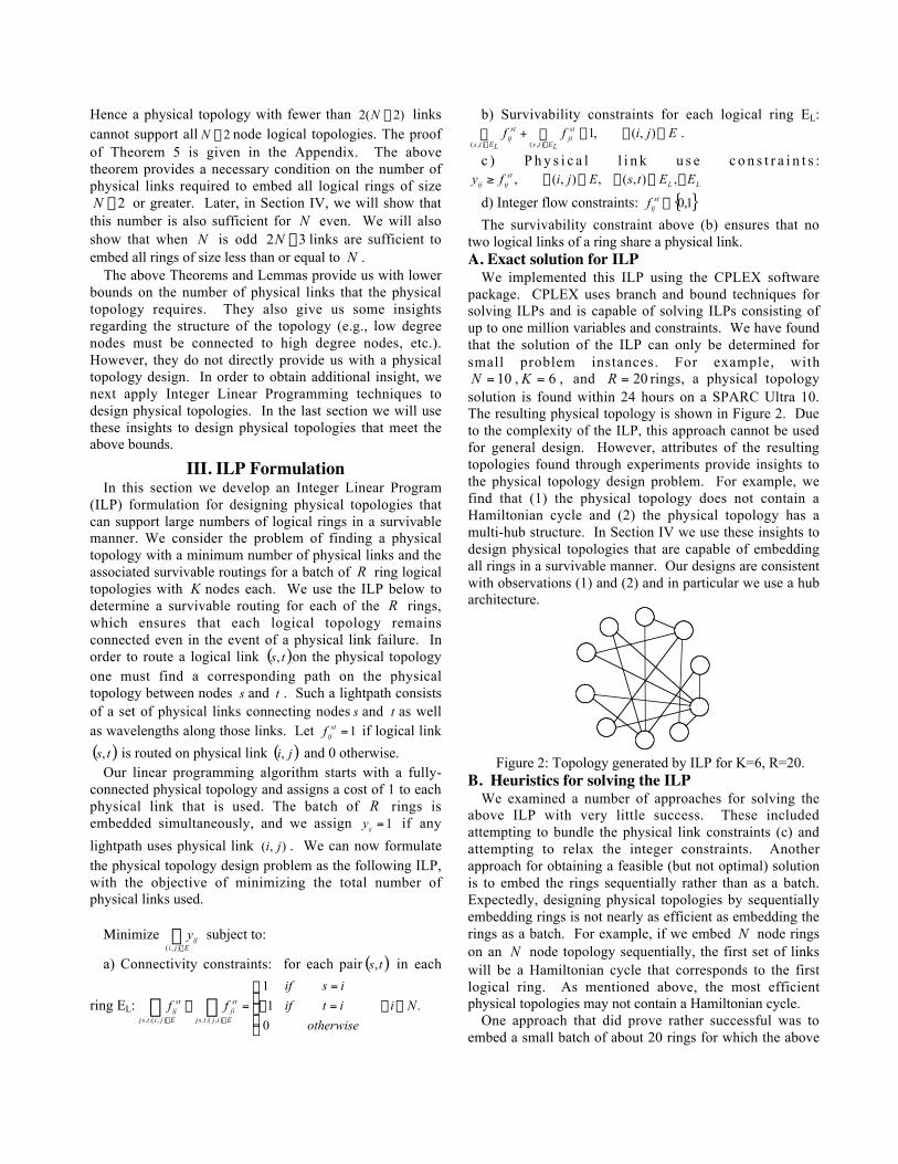
10=N , 6=K , and 20=R rings, a physical topologysolution is found within 24 hours on a SPARC Ultra 10.The resulting physical topology is shown in Figure 2. Dueto the complexity of the ILP, this approach cannot be usedfor general design. However, attributes of the resultingtopologies found through experiments provide insights tothe physical topology design problem. For example, wefind that (1) the physical topology does not contain aHamiltonian cycle and (2) the physical topology has amulti-hub structure. In Section IV we use these insights todesign physical topologies that are capable of embeddingall rings in a survivable manner. Our designs are consistentwith observations (1) and (2) and in particular we use a hubarchitecture.
Figure 2: Topology generated by ILP for K=6, R=20.B. Heuristics for solving the ILP
We examined a number of approaches for solving theabove ILP with very little success. These includedattempting to bundle the physical link constraints (c) andattempting to relax the integer constraints. Anotherapproach for obtaining a feasible (but not optimal) solutionis to embed the rings sequentially rather than as a batch.Expectedly, designing physical topologies by sequentiallyembedding rings is not nearly as efficient as embedding therings as a batch. For example, if we embed N node ringson an N node topology sequentially, the first set of linkswill be a Hamiltonian cycle that corresponds to the firstlogical ring. As mentioned above, the most efficientphysical topologies may not contain a Hamiltonian cycle.
One approach that did prove rather successful was toembed a small batch of about 20 rings for which the above

ILP can be solved and then use the resulting physicaltopology to sequentially embed additional rings, addingphysical links when necessary. The intuition behind thisapproach is that by embedding the small batch we avoid thenegative effect that results from the sequential embeddingof the first few rings. Moreover, it is reasonable to expectthat the physical topology that results from embeddingeven a small batch is relatively close to the optimaltopology for larger batches.
Hence, we combined the two approaches above, usingthe ILP to embed a small batch of rings in order to obtainan initial physical topology and then using this physicaltopology to embed more logical rings sequentially, addingphysical links as required. Of course designing a physicaltopology in this manner that can provably support all ringsrequires embedding )!1( -N rings which is impractical for
large N , even if the design is done off-line. However, theprimary goal of this heuristic is to help obtain insight onthe architecture of a physical topology that is sufficient forsupporting all rings of size N . For 9=N , embedding abatch of ten logical 9 node rings led to the dual hubarchitecture with an extra link between the hub nodes. Thisarchitecture uses 15 links and can support all 9 node rings.We will show in the next section that this dual hub designwith N nodes can support all N node rings (for all N odd).
IV. Physical Topology designsThe analytical and simulation (ILP) results provide
valuable insights in designing physical topologies that cansupport ring permutations of various sizes. From Lemma1, we know that all degree 2 nodes must have neighbors ofdegree 4 or higher. The physical topologies designedthrough the ILP simulations all have hub structures, i.e., asmall number of nodes with large degree and the remainingnodes with small degree. These insights are used to designthe following physical topology which can support all ringpermutations of size 2-£ NK .
Dual Hub Architecture: Consider a physical topologywith N nodes, two of which are hub nodes. Each non-hubnode has degree 2 and is connected to both hub nodes. Thehub nodes each have degree 2-N .
An example of the resulting physical topology for10=N nodes is given in figure 3. The dual hub
architecture contains )2(2 -N bi-directional physical links,the minimum required by Theorem 5 for supporting all
2-N node rings. The dual hub architecture of figure 3 cansupport survivable routings of all logical rings ofsize 2-£ NK (for N even). To show this we examine thecases where the logical ring contains 0,1, or 2, of the hubnodes. First consider the case where the ring logicaltopology contains none of the hub nodes. Starting with anynode in the logical ring, a path can be found to the nextnode via one of the hub nodes. The path to the subsequentnode will then go through the other hub node. Thusconsecutive lightpaths in the logical ring alternate between
using each of the two hubs as intermediate nodes. Eachhub node can be used as an intermediate node
2)2( -N times, thus we can support 2-N lightpaths.
Proofs for the cases where the logical topology containsone or both hub nodes are similar.
Figure 3: Topology that supports all 2-N node rings.
For N even, the dual hub architecture of Figure 3 cansupport all size 1-N rings as well. For N odd, adding anadditional physical link connecting the two hub nodesallows all rings of size less than or equal to N to beembedded. Furthermore, when N is even it can be shownthat adding two diversely routed physical links to the dualhub architecture can support all rings of size N in asurvivable manner (using a total of 2N - 2 links).
Shown in figure 4 is a physical topology for embeddingrings of size 4=K (N=12). In this physical topologythere are only nodes of degree 2 and degree 4. All nodes ofdegree 2 are connected to two nodes of degree 4 and allnodes of degree 4 are connected to four nodes of degree 2.Thus, there are twice as many degree 4 nodes as degree 2nodes. This example can be generalized to all values of Ndivisible by 3 (N≥6). It can be easily shown that theresulting physical topology can support all rings of size
4=K . Since the above topology contains twice as manydegree 2 nodes as degree 4 nodes, clearly, it contains
34N physical links. By Theorem 2, this is the minimum
required to support all rings of size 4.
1
7 3
5
12
8
4
10
9
2
6
11
Figure 4: Physical topology for K=4.

V. ConclusionWe consider the problem of physical topology design for
embedding logical rings in a survivable manner. Thisproblem is particularly important for service providers thatdesign their fiber infrastructure in order to support futurecustomer requests for lightpath connections. Since ringsare a very commonly used logical topology (due to theirability to recover from failures), we focused in this paperon design for ring logical topologies. Of course, a naturalextension of this work is general design for arbitrary (2-connected) logical topologies.
We obtained some basic necessary conditions on thephysical topology in order to be able to route logical ringsin a survivable manner. We also developed tight lowerbounds on the number of links that the physical topologymust contain in order to be able to support all possiblelogical rings of size K (for various values of K ). Finally,we designed a number of basic physical topologies thatmeet these bounds. One interesting result of our work isthat these physical topologies tend to have a multi-hubarchitecture. An important area of future work is toconsider designs that do not use a hub architecture.
Finally, one may question our desire to support all Knode logical rings in a survivable manner. The questionarises of whether we are over provisioning the physicalnetwork in our quest to support all logical rings. Notice,however, that our designs use fewer than N2 physicallinks to support all logical rings of size N or smaller. Anarbitrary N node logical topology requires a minimum ofN physical links in order to be 2-connected. Furthermore,our experiments show that attempting to embed just a smallnumber of logical rings requires very close to N2 physicallinks; hence, requiring the design to support all possiblelogical rings in fact does not result in a significant numberof additional physical links. Moreover the ability tosupport all logical rings is useful because it allows thelogical ring topology to be reconfigured. Suchreconfiguration has been shown to reduce network trafficloads[12,13].
Appendix: Proofs of TheoremsBefore proceeding to the proof of Theorem 3, we must firstgive the following useful Lemma.
Lemma 2: A node of degree 4 or degree 5 can have aphysical link to at most one node of degree 2.
Proof: Suppose two nodes of degree 2 have physicallinks to the same node of degree 5. Then the cut setconsisting of the two degree 2 nodes and the degree 5 nodecontains only five links, which is less than the 6 linksrequired by Theorem 1.
Proof of Theorem 3: Let id be the number of nodes
with degree i in the physical topology. Then the numberof links in the physical topology, L , is
†
L =idi2
i= 2
N-1
 = d2 +3d3
2+ 2d4 +
5d52
+idi2
i= 6
N-1
 . (7)
From Lemma 1 we know that nodes of degree 2 musthave physical links to nodes of degree 4 or higher and fromLemma 2, we know that at most one degree 2 node canhave a physical link to each node of degree 4 or degree 5,therefore
†
d2 £d42
+d52
+i2
i= 6
N-1
 di . (8)
Substituting Eq. (8) into Eq. (7) yields
†
L ≥ 2d2 +32
d3 +32
d4 + 2d5 . (9)
Since nodes of degree i add a minimum of 2i physical
links to the physical topology,
†
L ≥2d2 + 3d3 + 4d4 + 5d5 + 6(N - d2 - d3 - d4 - d5)
2
= 3N - 2d2 -32
d3 - d4 -32
d5
(10)
Equations (9) and (10) require that the number ofphysical links must be
†
L ≥ max(2d2 +3d3
2+
3d4
2+ 2d5,3N - 2d2 -
3d3
2- d4 -
3d5
2) . (11)
We can determine the values of 2d , 3d , 4d , and 5d that
minimize the number of physical links required. Theminimum value occurs when,
54325432 2
3
2
3232
2
3
2
32 ddddNdddd ----=+++ , i.e.,
when 2
2
5
2
533
2543
2
dddNd
---= . Substituting this
value of 22d into Equation (9) yields
†
L ≥3N2
+d44
+3d54
≥3N2
. (12)
QED.To prove Theorem 4, we first develop the following
three lemmas that are derived from Theorem 1.Lemma 3: A node of degree 6 or degree 7 can have
physical links to at most two nodes of degree 2.Proof: Suppose three nodes of degree 2 have physical
links to a single degree 7 node. Then the cut set consistingof the three degree 2 nodes and the degree 7 node containsonly seven links, which is less than the 8 links required byTheorem 1.
Lemma 4: A degree 3 node can have a physical link toat most one other degree 3 nodes.
Proof: Suppose a node of degree 3 has physical links totwo other nodes of degree 3. Then the cut set consisting ofthe three degree 3 nodes contains only five links, which isless than the 6 links required by Theorem 1.
Lemma 5: A degree 4 node can have physical links to atmost two degree 3 nodes.
Proof: Suppose a node of degree 4 has physical links tothree nodes of degree 3. Then the cut set consisting of thethree degree 3 nodes and the degree 4 node contains onlyseven links, which is less than the 8 links required byTheorem 1.

Proof of Theorem 4: Let id be the number of nodes
with degree i in the physical topology. Then the numberof links in the physical topology, L , is
†
L = d2 +3d32
+ 2d4 +5d52
+ 3d6 +7d7
2+
idi2
i= 8
N-1
 . (13)
From Lemmas 1, 2, and 3, we get the followingrestriction on the number of degree 2 nodes:
†
d2 £d42
+d52
+ d6 + d7 +i2
i= 8
N-1
 di. (14)
Substituting Eq. (14) into Eq. (13) yields
†
L ≥ 2d2 +32
d3 +32
d4 + 2d5 + 2d6 +52
d7 . (15)
Lemmas 4 and 5 yield the following restriction on thenumber of degree 3 nodes:
†
3d3 £ d3 + 2d4 + ii= 5
N-1
 di . (16)
Substituting Eq. (16) into Eq. (13) yields
†
L ≥ d2 +52
d3 + d4 . (17)
Since nodes of degree i add a minimum of 2i physical
links to the physical topology,
765432
765432
7
2
2
1
2
32
2
534
2
)(8
ddddddN
ddddddNidL i
i
------=
------+Â≥ =
. (18)
Equations (15), (17), and (18) require that the number ofphysical links must be
†
L ≥ max(2d2 +3d3
2+
3d4
2+ 2d5 + 2d6 +
5d7
2,d2 +
5d3
2
+d4,4N - 3d2 -5d3
2- 2d4 -
3d5
2- d6 -
d7
2)
(19)
We minimize the right hand side of Equation (19) usinga linear program to find that NL 55.1≥ for all values of N.QED.
To prove Theorem 5 we show that for any physicaltopology with fewer than )2(2 -N links, we can find an
2-N node ring logical topology where each logical linkrequires two physical links (for a total of )2(2 -N links).Hence a physical topology with fewer than )2(2 -N linkscannot support all 2-N node logical topologies. The proofof Theorem 5 uses Lemma 6 below.
Lemma 6: Consider an N node physical topology with52 -£ N physical links. Let id be the degree of the
thi largest degree node in the N node topology andassume each node has a minimum degree of two. Then
.2102
i
iNdi
+-£
Proof: Since there are at most 52 -N physical links inthe physical topology, the sum of the degrees of all thenodes must be less than or equal to 104 -N . Equivalently,
1041
1
1-£Â++Â
+=
-
=Nddd
N
ikki
i
kk . (20)
To determine an upper bound on id , move the sums on
the left hand side of Equation (20) to the right hand side.Since the degree of each node is at least two,
)(21
iNdN
ikk -≥Â
+=, thus
.2102
)(2104
1
1
1
1
Â-+-=
Â----£
-
=
-
=
i
kk
i
kki
diN
diNNd(21)
Since id is the degree of the thi largest degree node, we
know that its degree must be less than the average of the of
the larger degree nodes, i.e., 1
1
1
-
£
-
=
i
dd
i
kk
i . Equivalently,
)1(1
1-≥Â
-
=idd i
i
kk . (22)
Substituting Equation (22) into Equation (21) yields,
i
iNdi
2102 +-£ . (23)
Proof of Theorem 5: The proof is by construction of an2-N node logical topology that requires at least 42 -N
physical links. The proof is divided into four casescorresponding to physical topology size. In the first case,we show that the Theorem holds for all rings of size greaterthan or equal to 12. The other three cases establish theproof for rings of size less than 12.
In Case 1, we consider physical topologies ofsize 12≥N . We start by removing the two largest degreenodes from the physical topology. The resulting physicaltopology, P , has 2-= Nm nodes, with degrees 3d
through Nd . We show below that there exists a logical
ring topology that traverses these 2-N nodes and requiresmore than 52 -N physical links.
Consider the inverse of the m node physical topology,
denoted P)
, where if link Pji œ),( , then Pji)
Œ),( and if
Pji Œ),( , then Pji)
œ),( . We show below that there exists
a Hamiltonian cycle in this inverse graph. The existence ofa Hamiltonian cycle in the inverse graph implies that thereexists a sequence of 2-N nodes with direct physical linksconnecting them in the inverse topology. Hence, these
2-N nodes cannot be connected using direct physicallinks in the original physical topology, thus each logicallink must utilize at least two physical links in the originalphysical topology. Thus the logical ring correspondingto the Hamiltonian cycle in the inverse graph requires a
minimum of 42 -N physical links in the original topology.Next, we must prove our claim that a Hamiltonian cycleexists in the inverse topology. Let i be the index of the
thi largest degree node in the original topology and let id)
denote its degree in the inverse graph P)
. Since P)
has
2-N nodes, ii dNd --≥ 3)
. If some of the links of thethi largest degree node in the original topology were
connected to nodes 1=i and 2=i , then the degree of
node id)
is strictly greater than idN -- 3 . Thus 1+id)
can
be less than id)
. However, the degree of the smallest degree
node in P)
is always 33 dN --≥ and the degree of the
next smallest degree node is always 43 dN --≥ , etc. Let
je denote the degree of the thj smallest degree node in
P)
. Then 23 +--≥ jj dNe .
Before we can proceed we must cite the followingLemma which provides a sufficient condition for theexistence of a Hamiltonian cycle in a graph.
Lemma 7 [11, p.350]: Given a graph with m nodes withdegrees meee ££ ...21 . If je j > for 21 mj <£ , the
graph contains a Hamiltonian cycle.Applying the above Lemma to the inverse graph, the
inverse graph P)
contains a Hamiltonian cycle if the degreeof the nodes in the inverse graph are such that je j > for
21 mj <£ . Rewriting the requirement for a Hamiltonian
cycle in terms of id and N yields,
232 ->--≥- idNe ii for 12
3 +<£N
i . (24)
Using Equation (23) as an upper bound for id in
Equation (24), with some algebraic manipulation yields thefollowing requirement:
†
(N - i - 3)i - 2N +10 > 0 for 12
3 +<£N
i . (25)
The roots of the left hand side of equation (25) occur at2=i and 5-= Ni . Hence, Equation (25) is true if2>i and 5-< Ni . Thus, Equation (24) is satisfied if
512
-£+ NN
. Consequently, there exists a Hamiltonian
cycle in the inverse graph P)
for all 12≥N . The resultingHamiltonian cycle corresponds to a logical topology thatrequires for each logical link a minimum of two physicallinks in the original physical topology, i.e., this logicaltopology cannot be embedded in the original physicaltopology with fewer than 42 -N physical links.
For case 2, we consider physical topologies of size6=N and 7=N . Recall from Theorem 2 that a minimum
of 34N physical links are required to support rings of size
4. Since 3452 NN <- for 7£N , 4 node rings cannot
be supported, thus Theorem 5 holds. Similarly, case 3corresponds to physical topologies of size 8=N and
9=N . From Theorem 3, a minimum of 23N physical
links are needed to support rings of size 6. Again,2352 NN <- for 9£N and Theorem 5 still holds.
Finally, case 4 corresponds to physical topologies of size10=N and 11=N . Theorem 4 requires a minimum of
†
1.55 N physical links to support rings of size 8. Since
†
2N - 5 < 1.55 N for
†
N £ 11, Theorem 5 still holds and
†
2N - 5 < 1.55 N physical links are insufficient to supportrings of size 2-N for all
†
N £ 11.References:[1] S. Ramamuthy and B. Mukherjee, “Survivable WDMMesh Networks: Part I - Protection,” Infocom ‘99, NewYork, March, 1999.[2] S. Ramamuthy and B. Mukherjee, “Survivable WDMMesh Networks: Part II -Restoration,” ICC ‘99,Vancouver, CA, June, 1999.[3] O. Gerstel, R. Ramaswami, and G. Sasaki, “FaultTolerant Multiwavelength Optical Rings with LimitedWavelength Conversion,” Infocom ‘97, Kobe, Japan, April1997.[4] M. Medard, S. Finn and R. A. Barry, “WDM Loop-back Recovery in Mesh Networks,” Infocom ‘99, NewYork, March, 1999.[5] A. Fumagalli, et. al., “Survivable Networks Based onOptimal Routing and WDM Self-Healing Rings,” Infocom‘99, New York, March, 1999.[6] O. Crochat and J.Y. Le Boudec, “Design Protection forWDM Optical Networks,” IEEE JSAC, Vol. 16, No. 7,Sept. 1998.[7] B.T. Doshi, S. Dravida, P. Harshavardhana, O. Hauser,and Y. Wang, “Optical Network Design and Restoration,”Bell Labs Technical Journal, January-March 1999.[8] M. Kodialam and T.V. Lakshman, "MinimumInterference Routing with Application to MPLS TrafficEngineering," Infocom, 2000, Tel Aviv, Israel, April, 2000.[9] E. Modiano and A. Narula-Tam, "Survivable Routingof Logical Topologies in WDM Networks," Infocom 2001,Anchorage, AK, April 2001.[10] E. Modiano and A.Narula-Tam, "Survivable lightpathrouting: a new approach to the design of WDM-basednetworks," IEEE Journal of Selected Areas inCommunication, May 2002.[11] M.Gondran and M. Minoux, Graphs and Algorithms,John Wiley and Sons, 1984.[12] A. Narula-Tam and E. Modiano, “Load BalancingAlgorithms for WDM-based IP networks,” Infocom, 2000,Tel Aviv, Israel, April, 2000.[13] A. Narula-Tam and E. Modiano, “Dynamic LoadBalancing in WDM Packet Networks with andwithout Wavelength Constraints,” IEEE Journal ofSelected Areas in Communications, October 2000.