
DESIGNING HIGH PERFORMANCE STEAM TURBINES WITH ...
20
Stephen L. (Steve) Edney is Manager of Core Technology at Dresser-Rand’s Wells- ville Operation in New York. The Core Technology Department is responsible for the development, application, and trouble- shooting activities in aero/thermodynamics, materials science, rotordynamics, and stress analysis of steam turbines. Dr. Edney started his career in 1983 at GEC-Alsthom in the United Kingdom. He joined Dresser-Rand in 1991, and has since held supervisory positions in rotordynamics, and stress and vibration. Dr. Edney received B.Sc. (1983) and Ph.D. (1990) degrees (Mechanical Engineering) from the University of Nottingham, England, and is a member of ASME and the Vibration Institute, and an associate member of IMechE. He holds one U.S. Patent, and has authored numerous technical papers in rotor and bearing dynamics. George M. Lucas is Vice President of Project Management at Dresser-Rand’s Wellsville Operation in New York. The Project Management Department is respon- sible for the overall project management on all steam turbine new unit orders, including application and project engineering, pro- curement, and scheduling. Mr. Lucas began his career as a Design Engineer with FMC Coffin Turbo Pump Operation. He sub- sequently joined Dresser-Rand’s Steam Turbine Division in 1978, where he has since held a variety of positions in new product development, product engineering, and project management. Mr. Lucas received B.Sc. (1975) and M.Eng. (1976) degrees from Cornell University in Ithaca, New York. He holds two U.S. Patents, and has authored several technical papers on topics including the development of abradable seals for steam turbines, compressed air energy storage, and the development of syn-gas drive steam turbines. ABSTRACT The design, analysis, and testing of a high performance steam turbine driver for a critical service synthesis-gas compression train are discussed. The high power, high speed, double end drive and extraction condensing conditions of this type of machine present unique challenges to the rotor and flowpath design. These issues are discussed and test data presented that demonstrate the importance of considering the rotor’s dynamic characteristics at the design phase in order to build smoother and more reliable turbomachinery. INTRODUCTION Steam turbines first produced useful work well over a century ago. Their reliability, efficiency, and versatility are possibly the three main attributes that have contributed to their widespread utilization in a wide range of applications. Steam turbines can be found driving equipment ranging from generators, compressors, pumps, fans, and mills to the main propulsion units of marine vessels. They are employed in a variety of industries from utility, petrochemical, and mining to pulp and paper. Of the steam turbines employed in these industries, the most sophisticated and consequently challenging design is that which drives a synthesis- gas compressor of the type used in ammonia and methanol plants. Steam turbines that drive synthesis-gas compressors are required to operate at high speeds with high throttle flows and elevated inlet steam conditions. These turbines have condensing exhausts and often contain a controlled extraction that adds to bearing span and hence rotor flexibility. These features present unique challenges to the rotor and bearing design that must be carefully addressed to assure sound and reliable operation. For example, partial admission steam forces from the inlet and extraction sections can be large enough to affect bearing loading and, therefore, rotor response. Furthermore, the destabilizing forces from steam swirl in the high-pressure labyrinth seals and blade tip clearance leakage can be large enough to drive the rotor unstable. These issues are discussed along with other factors that must be considered in the design of a rotor for a high performance steam turbine. In the case study presented, the dynamic performance of the rotor was a prime consideration in establishing the main parameters of the design. Rotor geometries, such as bearing span, shaft diameter, wheel and overhung weight, along with the bearing and support structure properties, are parameters that can be varied to tune critical speeds in relation to the operating range and reduce response sensitivity to steam forces. The objective is to produce a design that not only complies with the requirements of any applicable specifications, but also one that has minimal dynamic sensitivity to external operational influences. Although the rotating component of a high performance steam turbine is reviewed, the analysis methodology presented can be used in the rotordynamics evaluation of all steam turbines. Furthermore, some of the features discussed can be incorporated into other steam turbine designs, as well as other types of turbomachinery. High Performance Steam Turbines In large scale petrochemical processes there is a fundamental need to compress gases to increase reaction rates in order to reduce 205 DESIGNING HIGH PERFORMANCE STEAM TURBINES WITH ROTORDYNAMICS AS A PRIME CONSIDERATION by Stephen L. Edney Manager, Core Technology and George M. Lucas Vice President, Project Management Dresser-Rand Company Wellsville, New York
Transcript of DESIGNING HIGH PERFORMANCE STEAM TURBINES WITH ...

Stephen L. (Steve) Edney is Manager ofCore Technology at Dresser-Rand’s Wells-ville Operation in New York. The CoreTechnology Department is responsible forthe development, application, and trouble-shooting activities in aero/thermodynamics,materials science, rotordynamics, and stressanalysis of steam turbines. Dr. Edney startedhis career in 1983 at GEC-Alsthom in theUnited Kingdom. He joined Dresser-Randin 1991, and has since held supervisory
positions in rotordynamics, and stress and vibration.Dr. Edney received B.Sc. (1983) and Ph.D. (1990) degrees
(Mechanical Engineering) from the University of Nottingham,England, and is a member of ASME and the Vibration Institute, andan associate member of IMechE. He holds one U.S. Patent, and hasauthored numerous technical papers in rotor and bearingdynamics.
George M. Lucas is Vice President ofProject Management at Dresser-Rand’sWellsville Operation in New York. TheProject Management Department is respon-sible for the overall project management onall steam turbine new unit orders, includingapplication and project engineering, pro-curement, and scheduling. Mr. Lucas beganhis career as a Design Engineer with FMCCoffin Turbo Pump Operation. He sub-sequently joined Dresser-Rand’s Steam
Turbine Division in 1978, where he has since held a variety ofpositions in new product development, product engineering, andproject management.
Mr. Lucas received B.Sc. (1975) and M.Eng. (1976) degreesfrom Cornell University in Ithaca, New York. He holds two U.S.Patents, and has authored several technical papers on topicsincluding the development of abradable seals for steam turbines,compressed air energy storage, and the development of syn-gasdrive steam turbines.
ABSTRACT
The design, analysis, and testing of a high performance steamturbine driver for a critical service synthesis-gas compression trainare discussed. The high power, high speed, double end drive andextraction condensing conditions of this type of machine presentunique challenges to the rotor and flowpath design. These issuesare discussed and test data presented that demonstrate the
importance of considering the rotor’s dynamic characteristics at thedesign phase in order to build smoother and more reliableturbomachinery.
INTRODUCTION
Steam turbines first produced useful work well over a centuryago. Their reliability, efficiency, and versatility are possibly thethree main attributes that have contributed to their widespreadutilization in a wide range of applications. Steam turbines can befound driving equipment ranging from generators, compressors,pumps, fans, and mills to the main propulsion units of marinevessels. They are employed in a variety of industries from utility,petrochemical, and mining to pulp and paper. Of the steam turbinesemployed in these industries, the most sophisticated andconsequently challenging design is that which drives a synthesis-gas compressor of the type used in ammonia and methanol plants.
Steam turbines that drive synthesis-gas compressors are requiredto operate at high speeds with high throttle flows and elevated inletsteam conditions. These turbines have condensing exhausts andoften contain a controlled extraction that adds to bearing span andhence rotor flexibility. These features present unique challenges tothe rotor and bearing design that must be carefully addressed toassure sound and reliable operation. For example, partialadmission steam forces from the inlet and extraction sections canbe large enough to affect bearing loading and, therefore, rotorresponse. Furthermore, the destabilizing forces from steam swirl inthe high-pressure labyrinth seals and blade tip clearance leakagecan be large enough to drive the rotor unstable. These issues arediscussed along with other factors that must be considered in thedesign of a rotor for a high performance steam turbine.
In the case study presented, the dynamic performance of therotor was a prime consideration in establishing the mainparameters of the design. Rotor geometries, such as bearing span,shaft diameter, wheel and overhung weight, along with the bearingand support structure properties, are parameters that can be variedto tune critical speeds in relation to the operating range and reduceresponse sensitivity to steam forces. The objective is to produce adesign that not only complies with the requirements of anyapplicable specifications, but also one that has minimal dynamicsensitivity to external operational influences.
Although the rotating component of a high performance steamturbine is reviewed, the analysis methodology presented can beused in the rotordynamics evaluation of all steam turbines.Furthermore, some of the features discussed can be incorporatedinto other steam turbine designs, as well as other types ofturbomachinery.
High Performance Steam Turbines
In large scale petrochemical processes there is a fundamentalneed to compress gases to increase reaction rates in order to reduce
205
DESIGNING HIGH PERFORMANCE STEAM TURBINESWITH ROTORDYNAMICS AS A PRIME CONSIDERATION
byStephen L. Edney
Manager, Core Technology
andGeorge M. Lucas
Vice President, Project Management
Dresser-Rand Company
Wellsville, New York

the size and cost of major components in the system. The requiredspeeds and powers are dictated by the compressor designer, andvary over a wide range depending on the molecular weight,flowrate, and pressure ratio of the gas being compressed. Heat toproduce steam typically comes from the process, and steam use istypically divided between a number of turbines and processheating requirements. Capital costs and process economics for theplant lead to moderate demands for thermodynamic economy ofthe steam turbines.
The ammonia manufacturing process offers some of the moredemanding challenges of steam turbine design. Figure 1illustrates a somewhat dated schematic of this process, and Figure2 a typical arrangement of the major steam turbines and theiroperating conditions. Most of the drivers operate on intermediatepressure steam extracted from the primary synthesis-gascompressor driver. This scheme allows the overall system to takeadvantage of the thermodynamic economy offered by relativelyhigh inlet steam conditions, while not burdening the lower powerdrivers with its efficiency compromising aspects. On the otherhand, the primary driver efficiency benefits from larger inletflows while the design of the low-pressure section is muchrelieved by extracting 80 percent or more of the flow at theintermediate pressure level.
Figure 1. Typical Ammonia Manufacturing Schematic.
Figure 2. Typical Arrangement of Steam Turbine Drivers in anAmmonia Plant.
Steam turbines that drive synthesis-gas compressors (hereaftercalled syn-gas turbines) operate with high throttle flows at elevatedinlet temperatures and pressures, and produce high power at highrotational speeds. These requirements present unique challengesthat, over the years, have culminated in some of the most
sophisticated steam turbine designs produced. Even so, in theirearly stages of development, turbine designers had to employ manydifferent concepts to overcome the then limitations in analyticalprediction methods, manufacturing technology, and materialsavailability.
The modern single casing syn-gas turbine shown in Figure 3 isthe culmination of a design evolution stretching over severaldecades. It was common practice at one time to build syn-gasturbines as two casing designs (Figure 4) with separate high-pressure and low-pressure turbines connected by a crossover duct.The exhaust from the high-pressure turbine supplied flow to meetthe process requirements with the remainder going to the low-pressure condensing turbine. At the time this was very effective,since the use of two casings avoided many compromises in bothrotor and flowpath design. Each turbine section was relatively shortin length, and rotordynamics problems relatively minor and easilydealt with. Moreover, with two relatively short rotors, there wereno serious restrictions on flowpath design and hencethermodynamic efficiency.
Figure 3. Modern Single Casing Syn-Gas Drive Steam Turbine.
Figure 4. Early Double Casing Syn-Gas Drive Steam Turbine.
PROCEEDINGS OF THE 29TH TURBOMACHINERY SYMPOSIUM206

DESIGNING HIGH PERFORMANCE STEAM TURBINES WITH ROTORDYNAMICS AS A PRIME CONSIDERATION 207
Ultimately, simple economics provided the impetus for thedevelopment of the single casing syn-gas turbine. Two casingdesigns were complex and expensive, with duplication of bearingand support systems, two complete casing and rotor systems, anadditional coupling, and a crossover duct. In addition to the obviousinitial capital cost, many of these extra components requiredmaintenance and periodic replacement. Space requirements andinstallation complexity were additional factors that eventuallyprovided the incentive for the development of the single casingdesign. A side benefit of this design was an improvement in overallefficiency due to the elimination of the crossover duct and one setof journal and thrust bearings and associated losses as well as steamleakage. These designs first appeared approximately 30 years ago,and quickly became the industry standard. Over the interveningyears, continued refinement and development have yieldedsignificant improvements in thermodynamic efficiency, mechanicalreliability, and rotordynamics performance compared to those earlydesigns. Presented herein is the case study of the rotordynamicsdesign, analysis, and verification testing of a modern single casingsyn-gas turbine.
SYN-GAS DRIVE STEAM TURBINE
Figure 5 depicts a cross section of a new generation syn-gasturbine typical for both ammonia and methanol processes. Theturbine is a single casing design with high-pressure andtemperature inlet, a controlled extraction, condensing exhaust, anddouble extended shaft ends to drive one or more compressors fromeach end. The basic design of the high-pressure inlet section iscapable of operating steam conditions of up to 2000 psig and1000°F. The overall unit is roughly 11 ft long by 10 ft wide by 12ft high, and weighs approximately 100,000 lb.
Figure 5. Cross Section of Single Casing, Single Flow Syn-GasDrive Steam Turbine.
The turbine application of this case study can produce nominally40,000 hp, and has a design operating speed range from aminimum governor of 8077 rpm to a maximum continuous of10,601 rpm. The flowpath consists of a two-stage high-pressurehead end and a five-stage condensing section as shown in Figure 6,which depicts the rotor in the lower half casing. The high-pressureturbine casing is a composite fabricated from several low alloy andcarbon steel castings, while the condensing exhaust casing is afabrication of carbon steel plate and structural shapes. The entirecasing, extraction control section, and exhaust were specificallydesigned to minimize the overall bearing span to produce a rigid,nonresponsive rotordynamic system. Equally, the flowpath wasspecially developed to meet the demanding simultaneous
requirements of high thermodynamic efficiency and high bladingreliability.
Figure 6. Rotor Supported in Lower Half of Steam Turbine Casing.
High-Pressure Section
Various options were evaluated in depth before the finalconfiguration of the high-pressure section was established. Severalfactors influenced the final design. Syn-gas processes aresomewhat unique in the high rate of extraction required of theturbine. Eighty percent or more of the total steam flow is typicallyextracted at relatively high pressure. This means that a majorportion of the total turbine power is produced in the high-pressuresection. Consequently, the thermodynamic efficiency of thissection is critical to the success of any syn-gas turbine design.
Motivated by this obvious concern with improving efficiency, aninner barrel style steam end was one of the first options considered.In an inner barrel design, the inlet nozzle passages, nozzle ring, andone or more subsequent stages are contained in a second casesupported inside the main turbine casing (Figure 7). Since the inletand stage pressures are contained inside two casings, each of whichsees only a portion of the total pressure, this design is capable ofmaintaining very high first stage pressure. Consequently, thecasing design is very conservative regarding both basic stresslevels and sealing. With its high pressure capability, theperformance potential with an inner barrel can be optimized withup to a three-stage high-pressure turbine section.
However, an inner barrel design suffers from a fewdisadvantages. To maintain high first stage pressure, an effectiveshaft seal at the rotor’s penetration of the inner barrel is necessary.This adds significantly to the required shaft length, and leakagethrough these seals dilutes the performance benefit of the highstage pressure. To truly optimize the efficiency of a three-stagehigh-pressure design would require a smaller flowpath, and henceshaft diameter, than is desirable for good rotordynamics.
An alternative to the inner barrel, used very successfully onother applications, is the finger type (Figures 8 and 9). In this

PROCEEDINGS OF THE 29TH TURBOMACHINERY SYMPOSIUM208
Figure 7. Inner Barrel Supported in Main Turbine Casing.
design, the high-pressure inlet steam is contained by two pressurecasings. Inlet steam is conveyed to the nozzle ring by separatenozzle passages (or fingers) suspended inside the outer casing. Thepressure contained by the single shell, or main outer casing, is thenlimited to first stage pressure. A disadvantage of this design,however, is that it has lower first stage pressure capability thanwith an inner barrel.
Figure 8. Schematic Showing Finger Passages Suspended InsideMain Turbine Casing.
Nevertheless, the single casing design turns out to be anexcellent compromise. By optimizing the high-pressure section asa two-stage design, the resulting larger flowpath diameter permitsa correspondingly larger shaft diameter. With elimination of theinner barrel’s extra set of shaft seals and associated leakage losses,the performance of the two-stage design approaches that of thethree-stage design, but in a much shorter axial space. Since two-thirds of the power is developed in this section, every one percentgain in efficiency equates to two-thirds of a percent increase inoverall turbine efficiency. Optimum performance, therefore, mustbe accomplished through proper selection of the wheel diameterand number of stages.
Figure 9. Nozzle Bowl Passages in Upper Half of Main Casing.
The finger type inlet with a two-stage high-pressure section wasultimately chosen as the optimum for the syn-gas turbinediscussed. Axial entry fir tree roots were used on the blades towithstand the high steam bending loads imposed on these stagesand integral shrouds with a friction band for additional damping(Figure 10). An additional benefit with axial roots is a morecompact wheel design that yields shorter bearing spans comparedto the use of more conventional tangential entry roots. Grade 422stainless steel was used for these blades due to the higher stagetemperatures. This configuration resulted in good thermodynamicefficiency, and a combination of axial spacing and shaft diameterthat was conducive to excellent rotordynamic characteristics.
Figure 10. High-Pressure Rotating Blades.
The high-pressure section of the turbine is supported by the inletend bearing case. This assembly primarily houses the journal andthrust bearings, although it also contains other devices such as theturning gear and control instrumentation. Special care must be takento ensure that the support structure has high vertical and lateralstiffness, particularly under the journal bearing, for proper control ofrotor response behavior. The assembly, however, also has to beflexible enough to allow for the large axial thermal expansion of theturbine casing, which can be as much as 0.375 in. The supportarrangement adopted is illustrated in Figure 3. For additionalvertical and lateral stiffness under the journal bearing, a doubleflexible plate is used for the inboard support. The outboard flexibleplate is preloaded slightly inboard to provide a self-leveling
DESIGNING HIGH PERFORMANCE STEAM TURBINES WITH ROTORDYNAMICS AS A PRIME CONSIDERATION 209
mechanism. This works by allowing the front end of the bearingcase to rise a predetermined amount as the outboard plate straightensdue to the axial growth of the casing. This rise compensates for thelarger thermal growth at the inboard support, which is considerablyhotter than the outboard support due to heat conduction andradiation from the turbine casing. This configuration wasintentionally designed to prevent unequal loading of the active thrustbearing from excessive case pitching exceeding the misalignmentcapability of the bearing. This condition has been a problem onsome earlier designs of syn-gas turbine resulting in excessive andunequal thrust bearing temperatures.
Low-Pressure Section
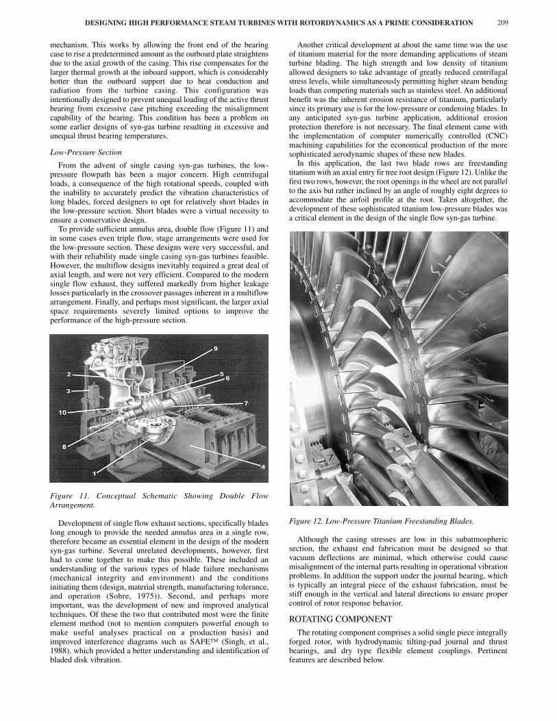
From the advent of single casing syn-gas turbines, the low-pressure flowpath has been a major concern. High centrifugalloads, a consequence of the high rotational speeds, coupled withthe inability to accurately predict the vibration characteristics oflong blades, forced designers to opt for relatively short blades inthe low-pressure section. Short blades were a virtual necessity toensure a conservative design.
To provide sufficient annulus area, double flow (Figure 11) andin some cases even triple flow, stage arrangements were used forthe low-pressure section. These designs were very successful, andwith their reliability made single casing syn-gas turbines feasible.However, the multiflow designs inevitably required a great deal ofaxial length, and were not very efficient. Compared to the modernsingle flow exhaust, they suffered markedly from higher leakagelosses particularly in the crossover passages inherent in a multiflowarrangement. Finally, and perhaps most significant, the larger axialspace requirements severely limited options to improve theperformance of the high-pressure section.
Figure 11. Conceptual Schematic Showing Double FlowArrangement.
Development of single flow exhaust sections, specifically bladeslong enough to provide the needed annulus area in a single row,therefore became an essential element in the design of the modernsyn-gas turbine. Several unrelated developments, however, firsthad to come together to make this possible. These included anunderstanding of the various types of blade failure mechanisms(mechanical integrity and environment) and the conditionsinitiating them (design, material strength, manufacturing tolerance,and operation (Sohre, 1975)). Second, and perhaps moreimportant, was the development of new and improved analyticaltechniques. Of these the two that contributed most were the finiteelement method (not to mention computers powerful enough tomake useful analyses practical on a production basis) andimproved interference diagrams such as SAFE™ (Singh, et al.,1988), which provided a better understanding and identification ofbladed disk vibration.
Another critical development at about the same time was the useof titanium material for the more demanding applications of steamturbine blading. The high strength and low density of titaniumallowed designers to take advantage of greatly reduced centrifugalstress levels, while simultaneously permitting higher steam bendingloads than competing materials such as stainless steel. An additionalbenefit was the inherent erosion resistance of titanium, particularlysince its primary use is for the low-pressure or condensing blades. Inany anticipated syn-gas turbine application, additional erosionprotection therefore is not necessary. The final element came withthe implementation of computer numerically controlled (CNC)machining capabilities for the economical production of the moresophisticated aerodynamic shapes of these new blades.
In this application, the last two blade rows are freestandingtitanium with an axial entry fir tree root design (Figure 12). Unlike thefirst two rows, however, the root openings in the wheel are not parallelto the axis but rather inclined by an angle of roughly eight degrees toaccommodate the airfoil profile at the root. Taken altogether, thedevelopment of these sophisticated titanium low-pressure blades wasa critical element in the design of the single flow syn-gas turbine.
Figure 12. Low-Pressure Titanium Freestanding Blades.
Although the casing stresses are low in this subatmosphericsection, the exhaust end fabrication must be designed so thatvacuum deflections are minimal, which otherwise could causemisalignment of the internal parts resulting in operational vibrationproblems. In addition the support under the journal bearing, whichis typically an integral piece of the exhaust fabrication, must bestiff enough in the vertical and lateral directions to ensure propercontrol of rotor response behavior.
ROTATING COMPONENT
The rotating component comprises a solid single piece integrallyforged rotor, with hydrodynamic tilting-pad journal and thrustbearings, and dry type flexible element couplings. Pertinentfeatures are described below.

Rotor Design
For applications up to a maximum stage temperature of 900°F,an ASTM A470 Class 4 rotor material is used. Wheel stresses arelimited by design to acceptable levels in order that the Class 4material can be used since it has significantly better ductility thanmost alternate materials. When maximum stage temperaturesexceed the capability of the Class 4 material, a specialdifferentially heat-treated material developed for high temperaturecondensing turbines is substituted. This material exhibits ductilitysimilar to Class 4 at low temperatures, but has improved strengthin the high temperature section.
As with any engineered steam turbine, first consideration must begiven to the design of the flowpath for optimum thermo-dynamicefficiency. This, however, has to be achieved with due regard to themechanical integrity of the blading from a stress and frequencyconsideration. In the high-pressure end of a syn-gas turbine, forexample, the blades have to be rugged enough to withstand the hightemperature of the inlet steam, as well as the high centrifugal andhorsepower bending loads acting on these stages.
The rotor design, therefore, is largely dictated by the size of theflowpath, as well as other features such as the size of the inlet,exhaust, and provision for any extraction or induction sections.Thus, the basic rotor geometry, such as the allowable maximumshaft diameter and minimum bearing span, is well established longbefore any dynamics evaluation can be performed.
The flowpath design and high rotational speed of a syn-gasturbine directs the operation to between the second and thirdmodes. The third mode, which is the first purely flexural mode, isthe most responsive by far and can limit the maximum allowableoperating speed. Thus, due consideration must be given tomaximizing the shaft stiffness while minimizing the overhungweight. Since, however, the maximum shaft diameter is limited bythe flowpath and blading design, particular attention has to bedirected toward reducing the overhung weight.
Referring to Figure 13, the inlet end overhung weight wasreduced by incorporating a double thrust collar arrangement. Theoutboard thrust collar is integral with the rotor, and provides aflanged face for a coupling. Sandwiched between the collar and thecoupling flange is the driven wheel of a turning gear. This wheel alsoprovides the reference signal for the speed pickups of an electronicgovernor, and eliminates the need for a separate toothed wheel. Theinboard thrust collar is an extended shoulder off the shaft penetratingthe bearing case. Axial position probes were also included that readoff the outboard face of the turning gear/speed pickup wheel. At theexhaust end, the end gland packing case was tucked inside thediffuser to reduce overhung weight as shown in Figure 5. This alsomoved the centerline of the bearing further inboard, thus eliminatingextraneous span. The coupling flange was left integral, with a shaftriding grounding brush located between it and the bearing.
The end result was a rotor with an overall length of 111.3 in,bearing span of 96.0 in, and midspan diameter of 13.0 in. Forincreased shaft stiffness through both overhangs, the diameterestablished for both journal bearings was 5.0 in. Radial shaftvibration probes were provided inboard of each journal bearing, 45degrees either side of top dead center. Two externally accessiblefield trim balance planes were also included, one located near eachend of the central shaft section. This design also has provision fora third plane near the rotor’s midspan, adjacent to the downstreamface of the wheel immediately upstream of the extraction section.
Bearing Design
Tilting-pad journal and thrust bearings are almost exclusivelyused in modern high speed turbomachinery. Compared to thefixed geometry sleeve type, tilting-pad journal bearings haveexcellent stiffness and damping properties that reduce a rotor’ssensitivity to unbalanced forces, and far superior stability charac-teristics at high speeds. Offset-pivoted, self-equalizing tilting-padthrust bearings are used for their excellent load sharing and load
Figure 13. Inlet End Arrangement Showing Shaft OverhangProportions.
carrying characteristics. Two disadvantages of tilting-pad bearings,however, are the escalating oil film temperatures and frictionallosses at high speeds as operation extends into the turbulent regime(Mikula and Gregory, 1981; Edney, 1995).
Over the past decade or so, these issues have been addressedwith the development of directed lubrication technology. Thesenew designs provide increased load carrying capacity and reducedfrictional losses at lower oil flowrates, without increasing themaximum oil film temperature. The operational performances ofseveral directed lubrication journal bearing designs have beenstudied (Edney and Mellinger, 1997) and today are widely appliedin a variety of turbomachinery.
High efficiency leading edge groove tilting-pad journal andthrust bearings were chosen for this application. For synchronousresponse and stability reasons, the journal bearing selected was acentrally pivoted, four pad design, orientated load between pivot asshown in Figure 14. The pads have integrally crowned pivots thatprovide axial alignment capability. Fixed open clearance end sealsallow the spent hot oil to exit the bearing axially without restrictionand contamination of the fresh cool supply oil. Oversize drain slotsmachined into the bottom of the housing prevent the bearing cavityfrom partially flooding with associated churning losses.
Figure 14. Leading Edge Groove Tilting-Pad Journal Bearing.
Both thrust bearings, illustrated in Figure 15, were a 65 percentoffset-pivoted, self-equalizing design with eight shoes per side.
PROCEEDINGS OF THE 29TH TURBOMACHINERY SYMPOSIUM210

DESIGNING HIGH PERFORMANCE STEAM TURBINES WITH ROTORDYNAMICS AS A PRIME CONSIDERATION 211
The number of shoes and pivot offset selected were chosen tomaximize the load carrying capacity within the available envelope,while maintaining a conservative oil film temperature. The highreaction of the condensing blades used in syn-gas turbines canyield very high axial loads when the turbine is operated withoutextracting flow. Equally, the high surface speeds of the large boredesign dictated by the double end drive arrangement add to thechallenge of keeping operating shoe temperatures to acceptablelevels. For these reasons, a directed lubrication design is a virtualnecessity. Since shoe temperature is the primary concern from anoperational standpoint, other options that might be considered toreduce temperature include a 10-shoe design and chrome copperbacking material.
Figure 15. Leading Edge Groove Tilting-Pad Thrust Bearing.
Although the primary reason for using directed lubricationbearings was to address operating temperature, reduced frictionallosses and lower oil flowrates were desirable factors also.Temperature sensing instrumentation was in compliance with API670 (1990).
Bearing Support and Foundation
As already mentioned, the bearing supports should be designedto be as stiff as possible in the lateral and vertical directionsbetween the bearing and foundation for proper control of rotorresponse. The objective is to optimize the inherent damping withinthe bearings by maximizing the relative rotor motion at thebearings. This, in turn, increases the effectiveness of the availableoil film damping and ultimately minimizes the overall rotorresponse.
The most common foundation designs are relatively massivereinforced concrete structures that impart a high impedance to theturbine at the connection points. In this respect, they aredynamically similar to most test floor arrangements used duringfactory tests. Experience has shown that factory tests yield resultsthat are representative of operation in the field.
A case study that describes some of the rotordynamics problemsthat can occur from inadequate support stiffness is given in Bethel,et al. (1993).
Coupling Design
To minimize overhung weight, integrally coupled, highperformance, dry type flexible couplings were specified. Thesetypes of couplings do not require lubrication and need littlemaintenance compared to a gear design (Mancuso, et al., 1989).Also, for a given misalignment, the significantly lower bendingmoments produced by these couplings help to keep nonessentialshaft end stresses to a minimum.
Furthermore, flexible element couplings are extremelyaccommodating of axial thermal growth, since they can beinstalled in a prestretched condition. This helps to ensure that,under normal operating conditions, the couplings run in a neutralposition thus reducing the overall load on the thrust bearing. This
is a very desirable feature on a double end drive machine, such asa syn-gas turbine, where the axial thermal growth at the inlet endcan be as much as 0.375 in or more. The coupling specification wasin accordance with API 671 (1993).
Rotor Assembly and Balancing
To ensure a well-balanced rotor over the design operating range,a sequential assembly and balance procedure was used. A typicalsequence on a solid rotor such as this is to drive the blade rows twoat a time starting at the center and working out. The blades shouldbe individually weighed and intentionally arranged so as tominimize the resultant unbalance at each wheel to reduce theamount of grinding or correction weights added. After two wheelshave been driven, the rotor should be dynamically balanced acrossthe driven wheels in a low speed balance machine with correctionsmade only to the driven wheels. This sequence should be followedworking toward the shaft ends until all the wheels have beendriven. Any shrunk-on components should be added as appropriatein the balance sequence, with corrections made to each componentafter it is added. This careful and sequential method of assemblyand balancing will ensure that a rotor will run from zero to tripspeed with minimal levels of vibration.
ROTORDYNAMICS ANALYSIS
The mass elastic model generated of the turbine rotor (Figure16) is shown in Figure 17. External weights that do not contributeto lateral stiffness (such as the blading, turning gear wheel, andcoupling half-weights) are included in the model as indicated bythe vertical arrows. The rotor profile of Figure 17 illustrates therotor stiffness variation assumed through the wheels. At abruptchanges in diameter, such as at the location of a wheel, theeffective stiffness diameter follows a more gradual path. The slopeof this stiffness path is widely regarded as following a 45 degreeline, which is often referred to as the 45 degree rule. Since,however, most rotordynamics analysis programs are based oncylindrical shaft elements, an average diameter is typically used asthe effective stiffness diameter.
Figure 16. Rotor Viewed from Inlet End.
Figure 17. Mass-Elastic Model of Rotor.

The shape and number of elements used to represent the rotoralso should be considered carefully. In general, the aspect ratio(length-to-diameter) of each element should not exceed 1.0, andthe number used sufficient that adding more would have minimaleffect on the results. With today’s computing power, there is noreason to economize on the number of elements used to model therotor. More elements will also yield smoother and more accuraterotor mode and deflected shape response plots.
Support Stiffness
The importance of including the support properties beyondthe journal bearing oil film has long been recognized. The totalbearing support structure is highly complex, and thus difficult torepresent analytically. At the design stage, the determination ofaccurate values is somewhat nebulous, due to the complexshapes of the support structure, and uncertainties in boltedjoints, grout, and other factors. Thus, a simple idealization isoften used.
The approach typically used is to include a simple singledegree of freedom spring-mass-damper model in series with theoil film. The values used are largely based on experience for agiven size of machine and design of bearing case and support.The overall stiffness can be mathematically and/or experimen-tally approximated from the static deflection of the supportstructure. Values for the support mass and damping, however,often require additional calculations or approximations. Whilethis approach can be used to adequately predict both the loca-tion and amplification factor of a rotor’s peak response speeds,it will not yield more than a single support or foundationresonance.
Clearly, simple mathematical models cannot accuratelyrepresent the complexity of the various connected structures thatexist between the bearings and solid ground. To address this,mechanical impedance test procedures and equipment weredeveloped (Coleman, 1958) to measure the dynamic character-istics of the total support structure at the bearing interface. Twoof the earliest applications to rotordynamics analysis in whichbearing case supports were experimentally tested to obtainmechanical impedance data are presented in Caruso, et al.(1982), and Barrett, et al. (1986). The experimental data isdetermined from modal analysis techniques where the responseof the structure to a known applied force is recorded. Theresulting frequency response function (FRF) data, bothmagnitude and phase, ideally should be plotted as a function ofspeed. If the magnitude of the FRF is displacement divided byforce, then the resulting data is called a dynamic compliance(Ewins, 1984). One advantage of this method is that the supportmass and damping are included implicitly in the FRF along withthe support stiffness. These data can then be incorporated intothe rotordynamics support model as speed dependent dynamicstiffnesses over the speed range of interest. This informationshould be obtained to ensure that the support model used in theanalysis is adequately representative, and that there are no areasof structural weakness at operating speeds of concern. It mayalso be required if the unbalance response test data do notcorrelate well with the analytical model.
The experimental procedure is quite straightforward, andrequires either a modal or spectral analyzer. A block diagram ofthe test arrangement is illustrated in Figure 18. An impacthammer (or shaker) is used to excite the bearing case at thebearing centerline. An internal load cell registers the forceimparted by the hammer on the bearing case. Mounted on thebearing case at the centerline is an accelerometer that senses theresultant motion of the bearing case from the impact force. Themodal analyzer double integrates the acceleration and dividesthe resulting displacement by the force. This integration anddivision are the compliance FRF containing both amplitude andphase information. These data can then be input into the support
model used for the forced response analysis. An example of acompliance FRF plot is shown in Figure 19 of the inlet endbearing case. A discussion of the theory and application of thisprocedure with supporting data can be found in Nicholas, et al.(1986).
Figure 18. Modal Analysis Schematic Diagram.
Figure 19. FRF Compliance Plot—Inlet End Vertical.
Undamped Critical Speed Map
An undamped critical speed map is a logarithmic plot of arotor’s lateral undamped resonant speeds versus support stiffness.The term critical speed, however, is often used when referring tothe resonant speeds of a rotor as adopted by most industrystandard specifications (API 612, 1995). The undamped criticalspeed map generated for the syn-gas turbine is illustrated inFigure 20 for the first three modes. Critical speeds areapproximated by overlaying on this map the speed dependentdynamic stiffnesses of the total support system. This methodcombines the bearing and support characteristics into anequivalent dynamic stiffness (Caruso, 1958). The inferred criticalspeeds are clearly very dependent on the curves constructed fordynamic stiffness.
In the absence of any test data, an isotropic single degree offreedom support model was used at both journal bearings. The
PROCEEDINGS OF THE 29TH TURBOMACHINERY SYMPOSIUM212
DESIGNING HIGH PERFORMANCE STEAM TURBINES WITH ROTORDYNAMICS AS A PRIME CONSIDERATION 213
Figure 20. Undamped Critical Speed Map.
stiffness and mass values assumed were based on experience ofsimilar support designs, and the damping 10 percent of critical asin Nicholas and Barrett (1986). Values of 4.0 � 106 lb/in and 500lb, respectively, were used for the support stiffness and mass ateach bearing. The same support model was also used in theunbalance response and stability analyses.
Plotted on Figure 20 are two sets of dynamic stiffness curves.The curve with the higher dynamic stiffness is of the bearing oilfilm alone. The second curve is of a series combination of thebearing and support. Although the primary determining factor isthe bearing oil film, the inherent flexibility of the supportstructure beyond the bearing must be accounted for to accuratelyrepresent the total support system. As can be seen from Figure 20,neglecting the support structure beyond the bearing could leadone to the conclusion that a rotor’s critical speeds are higher thanactual.
Unbalance Response
An undamped critical speed map provides only a convenientmeans of quickly assessing the location of modes in relation tothe operating speed range. No specific information regarding theseverity of the response, however, is available. This is bestevaluated by calculating the synchronously forced response tounbalance versus speed. Since the response shape and hencepeak location is, to some extent, dependent on the unbalancescheme used, critical speeds identified from these plots are moreappropriately referred to as peak response speeds. Guidelines onthe amount and location of unbalance that should be used andthe acceptance criteria against which the results should bejudged are given in most industry standard specifications (API612, 1995).
First modes are logically excited by a single weight placed at therotor’s midspan. Second modes by two weights, one placed neareach end of the central shaft section 180 degrees out-of-phase.Third modes by three weights, one placed at the midspan with theother two at the shaft ends 180 degrees out-of-phase of the centralweight. This latter arrangement will ensure that the effect of anyshaft end overhung unbalance (such as from the coupling) isaccounted for in the determination of peak response speeds. Inaddition to the response at the bearings, it is normal practice tocheck all other close clearance points along the rotor for possiblerubs from zero to trip.
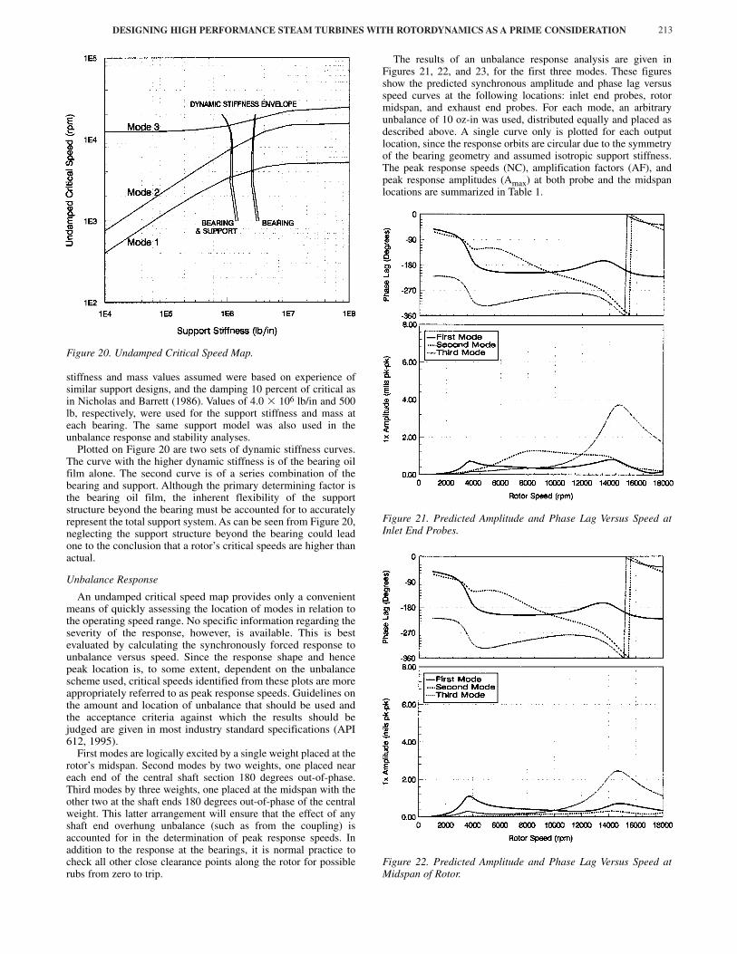
The results of an unbalance response analysis are given inFigures 21, 22, and 23, for the first three modes. These figuresshow the predicted synchronous amplitude and phase lag versusspeed curves at the following locations: inlet end probes, rotormidspan, and exhaust end probes. For each mode, an arbitraryunbalance of 10 oz-in was used, distributed equally and placed asdescribed above. A single curve only is plotted for each outputlocation, since the response orbits are circular due to the symmetryof the bearing geometry and assumed isotropic support stiffness.The peak response speeds (NC), amplification factors (AF), andpeak response amplitudes (Amax) at both probe and the midspanlocations are summarized in Table 1.
Figure 21. Predicted Amplitude and Phase Lag Versus Speed atInlet End Probes.
Figure 22. Predicted Amplitude and Phase Lag Versus Speed atMidspan of Rotor.

Figure 23. Predicted Amplitude and Phase Lag Versus Speed atExhaust End Probes.
Table 1. Peak Response Speed, Amplification Factor, and PeakResponse Amplitude at Both Probe and Midspan Locations.
The first peak response speed is highly damped, and well belowthe minimum governor speed. The separation margin comfortablymeets the 5.0 percent required by API 612 (paragraph 2.8.2.5b,1995) for a first mode amplification factor of less than 3.55. Thedeflected shape is what would classically be described ascylindrical, with the midspan amplitude approximately 50 percenthigher than at the probe locations.
At 8000 rpm, the second peak response speed is in the vicinityof the minimum operating speed. However, since this peakresponse speed has an amplification factor of below 2.5, it isconsidered to be nonresponsive or critically damped as defined inparagraph 2.8.1.3 of API 612 (1995). No separation margin isrequired, and operating the turbine on or near this peak responsespeed is allowed (paragraph 2.8.2.5a, 1995). Operatingturbomachinery on or near the second peak response speed inaccordance with API specifications has been addressed (Nicholas,1989). The deflected shape is what would typically be described asconical, with the response at the shaft ends 180 degrees out-of-phase and a nodal situation occurring near the midspan.
The third peak response speed, being the first purely flexuralmode, is the most responsive by far. The location of this peak alsosets the allowable maximum operating speed in accordance withthe API 612 formula for separation margin (paragraph 2.8.2.5d,1995). The deflected shape has two nodal situations, one near eachquarter span location. Of particular interest, however, is that themidspan amplitude is less than at the probes by more than 50percent. These results illustrate why the excitation of the overhungweight can be important in evaluating third modes. An unbalanceat the coupling, for example, could lead to higher responseamplitudes at the shaft ends than at the rotor’s midspan.
Effect of Rotor Geometry
So why not just lower the second peak response speedcomfortably below the operating speed? To some extent, changingthe geometry and hence stiffness of a rotor will move the locationof peak response speeds. Other factors, such as the bearing andsupport characteristics, also can be varied to tune the location ofpeak response speeds. Although such changes might address onemode, they also could adversely affect other modes of concernultimately degrading the overall rotor response characteristics overthe operating speed range.
For example, increasing the shaft stiffness of a relatively stiffrotor while maintaining the same bearing span will raise thelocation of the third peak response speed, but will have a minimalinfluence on the locations of the first and second. The magnitudeof the response to unbalance will change, however, due to theadditional weight supported by the bearings and associatedchanges in oil film stiffness and damping. Thus, the completerotorbearing system must be considered when tuning peakresponse speeds in relation to the operating range.
The effect of rotor geometry is illustrated in Table 2 for the sameunbalance schemes used in the baseline example. Illustrated is theeffect of a 6.0 in increase and decrease in bearing span, and a 2.0in increase in shaft diameter. These results are again compared interms of peak response speed, amplification factor, and peakresponse amplitude.
Table 2. Peak Response Speed, Amplification Factor, and PeakResponse Amplitude for First, Second, and Third Mode Response.
The third mode is clearly the most affected by changes in rotorgeometry. There is, however, a limit regarding how much the bearingspan can be shortened or the shaft diameter increased in an attempt toraise the third peak response for higher speed applications. Forexample, shortening the span will compress the flowpath, thusadversely affecting the efficiency. Similarly, increasing the shaftdiameter will increase the interstage and end gland leakage withassociated efficiency and operational stability ramifications.Furthermore, these changes also will likely raise the third modeamplification factor and peak response amplitudes, thus negatingsome of the increase in separation margin gained versus that required.
In contrast, the first and second peak response speeds are muchless sensitive to these moderate changes in rotor geometry. This is ofparticular interest regarding the second, since it cannot be loweredsignificantly by geometry changes alone. Other factors would have
PROCEEDINGS OF THE 29TH TURBOMACHINERY SYMPOSIUM214
MODE NC (rpm) AF (dim) Amax (mil pk-pk)
IE / MS / EE
First 3750 2.7 0.71 / 1.11 / 0.78
Second 8200 1.7 1.28 / 0.14 / 1.08
Third 14,600 5.4 3.62 / 2.45 / 6.04
First Mode Response
NC1 (rpm) AF1 (dim) Amax (mil pk-pk)
IE / MS / EE
6 in Span Increase 3600 3.1 0.73 / 1.22 / 0.78
6 in Span Decrease 3950 2.2 0.72 / 1.03 / 0.78
2 in Diameter Increase 3750 2.9 0.67 / 0.93 / 0.71
Second Mode Response
NC2 (rpm) AF2 (dim) Amax (mil pk-pk)
IE / MS / EE
6 in Span Increase 8000 1.8 1.31 / 0.13 / 1.12
6 in Span Decrease 8500 1.7 1.25 / 0.10 / 1.06
2 in Diameter Increase 8100 1.9 1.25 / 0.16 / 1.10
Third Mode Response
NC3 (rpm) AF3 (dim) Amax (mil pk-pk)
IE / MS / EE
6 in Span Increase 14,100 4.9 3.67 / 2.13 / 5.43
6 in Span Decrease 15,100 6.3 3.59 / 2.96 / 6.86
2 in Diameter Increase 15,800 8.0 4.08 / 2.91 / 7.82

DESIGNING HIGH PERFORMANCE STEAM TURBINES WITH ROTORDYNAMICS AS A PRIME CONSIDERATION 215
to be addressed, such as reducing the bearing stiffness, althoughthere is a limit on how much of a reduction could be achieved.Moreover, these changes would also lower the third peak responsespeed, which likely would be the limiting factor from a dynamicsconsideration. It can be seen then that there is a limit on how muchthe second peak response speed can be lowered (if at all in somecases) below the minimum governor speed of this type of machine,without increasing the sensitivity to unbalance at operating speed.
Thus, for optimum thermodynamic efficiency and rotordynamicperformance, an extraction-condensing syn-gas turbine of this typewhen operating near the low end of its speed range will be in theneighborhood of the second peak response speed. The key is toensure that the mode is well damped, and insensitive to externaloperational influences. Nevertheless, these limited resultsdemonstrate some of the rotor geometry changes that can beevaluated in an attempt to tune a rotor’s dynamic characteristics inrelation to the operating speed range.
Rotor Stability
Rotor stability continues to be one of the primary concerns inrotating machinery operating at high speeds and pressures. Anunstable condition will occur when the system destabilizing forcesare greater than the restoring damping or stabilizing forces.Destabilizing forces typically arise from oil film sleeve bearingsand seals, friction in shrink-fitted components, and aerodynamicexcitation. In steam turbines, aerodynamic sources are typically thelabyrinth seals and blade tip clearance leakage.
The prevailing method used in the evaluation of rotor stability isto calculate the damped eigenvalues and associated logarithmicdecrements. The imaginary part of the eigenvalue is the dampednatural frequency, while the real part is the growth exponent. Apositive growth exponent is indicative of an unstable system, and anegative value of a stable system. However, for practical reasons, itis more appropriate to convert the growth exponent into alogarithmic decrement. The logarithmic decrement is defined asthe natural logarithm of the ratio of two successive amplitudes of afreely oscillating system, and gives a measure of the systemdamping, or rate of vibration growth or decay, following adisturbing influence. Stability is assured with a positive value forlogarithmic decrement; the higher the value the more stable thesystem. When neglecting aerodynamic forces, a good rule ofthumb is that the logarithmic decrement at the maximum operatingspeed should be greater than 0.3 for assured stable operation.
Typical results are plotted on the whirl speed map of Figure 24,and do not include any destabilizing forces. Illustrated is the effectof rotor speed on the damped natural frequency and logarithmicdecrement of the first three whirl modes. Intersection of the whirlspeed curves with the synchronous response line gives theapproximate location of the first three damped critical speeds. Thevalues for logarithmic decrement noted in Figure 24, being greaterthan 0.3, are clearly indicative of a highly stable system over therange of shaft speeds plotted.
Aerodynamic Cross-Coupling
High-speed, high-pressure, steam turbines can be prone to self-excited vibration due to the flow of steam through peripheralclearances. The forces that cause these instabilities are oftenreferred to as aerodynamic since they are the result of fluid forcesacting on the rotor. In steam turbines there are two sources ofconcern: labyrinth shaft seals and blade tip clearance leakage.
Labyrinth shaft seals are the primary source of aerodynamicexcitation. The magnitude of the destabilizing force, and hence thelikelihood of unstable operation, increases with pressure, speed, androtor eccentricity. The destabilizing forces are a resultant combinationof the axial flow associated with the pressure drop across the seal plusthe accompanying fluid circumferential velocity due to shaft rotation.The axial component can be more easily explained by considering astationary rotor. As the rotor eccentricity increases, a larger averagepressure develops on the side of the seal with the smaller local
Figure 24. Whirl Speed and Logarithmic Decrement Versus RotorSpeed.
clearance and vice versa. The resultant pressure differential producesa restoring force that opposes the rotor displacement and acts torestore the rotor to the center of the seal, which can be represented asa direct stiffness. When the rotor starts to spin, the fluid forces actingon it become more complicated as illustrated in Figure 25 forclockwise rotation. As the rotor eccentricity increases the clearancecavity becomes progressively more convergent divergent. Similar to asleeve bearing, hydrodynamic effects cause an increase in pressure inthe converging region of the clearance area and a reduction inpressure in the diverging region. This pressure differential yields a netforce, Ft, tangential to the rotor’s displacement or, as illustrated forthe case in Figure 25, to the right in a clockwise (or forward whirl)direction around the center of the seal. The radial force component,Fr = (K � cω)e, is negligible for labyrinth seals. The tangential forcecomponent, Ft = (k � Cω)e, will either destabilize (Ft > 0) orstabilize (Ft < 0) a rotor in forward whirl. This condition propagatesin a self-excited manner producing forces that push the rotor to evenhigher vibration levels. The complete seal force model can beconveniently expressed in terms of linearized stiffness and dampingcoefficients as shown by the following equation (neglecting inertiaterms that are considered small for compressible flow seals):
Fx K k x C c x.
� = � (1)Fy �k K y �c C y.
Figure 25. Aerodynamic Seal Forces.
� � � � � �� � ��

The stability of a seal is largely dependent on the relativemagnitudes of the two primary terms; the destabilizing cross coupledstiffness k and the stabilizing direct damping C. Because of itsdestabilizing influence, the cross coupled stiffness k is the mostimportant of all the coefficients. The second most important,although in general the values are typically low, is the direct dampingC since positive values will counteract k. Nevertheless, there arereported cases of the measurement of negative direct damping thatwould have a destabilizing influence (Kurohashi, et al., 1980). Thedirect stiffness K is generally quite low and tends to have a smallinfluence on rotordynamics response and stability. Due to theinherent uncertainty in the prediction of these coefficients, as ageneral rule of thumb a conservative stability analysis would includeonly the destabilizing cross coupled stiffness values. This approachof ignoring the direct damping C, however, could lead to a somewhatpessimistic conclusion regarding the stability of a rotor system andso should be exercised with some caution. Further, if negative valuesof direct damping are calculated, then they must be included in thestability analysis to properly account for the destabilizing influence.The quantitative prediction of labyrinth seal force coefficients hasbeen the subject of significant research over the last two decades, andwill continue to be so for the foreseeable future.
A secondary aerodynamic source is from tip clearance leakageof the rotating blades in eccentric operation. Thomas (1958) firstpostulated this phenomenon in connection with instabilityproblems on steam turbines. Alford (1965) later identified the samemechanism associated with instability problems on aircraft gasturbines. In steam turbines these forces are usually neglected dueto their relatively small magnitude compared to the labyrinth sealforces. Nevertheless, they can be approximated using the followingformula (Thomas, 1958):
Kq = . (2)
where β is an empirical adjustment factor in the range 1.0 to 1.6,and represented through the following force equation:
Fx 0 Kq x� = (3)
Fy �Kq 0 y
The clearance excitation force is purely destabilizing without anydirect stiffness or damping. For the interested reader, theexperimental work of Urlichs (1976) on unshrouded, and Leie andThomas (1980) on shrouded tip leakage effects is suggested.Although these researchers have measured values for β of up tofive, experience has shown that for practical purposes a value of1.0 yields more appropriate results.
The resultant of all the destabilizing forces is opposed by therestoring damping of the hydrodynamic bearings. For this reason,tilting-pad designs are used due to their superior damping andinherent stability characteristics compared to sleeve types.Nevertheless, if the resultant destabilizing force is greater than theoverall damping, then large unbounded self-excited subsynchro-nous vibrations will occur. These vibrations typically appear at afrequency approximately equal to the fundamental lateral naturalfrequency of the rotor (Greathead and Bostow, 1976). There areexceptions, however, such as the case history presented by Haq, etal. (1998), of synchronous vibration instability associated with adamaged labyrinth seal.
For more information on the prediction and effect of seal and tipclearance forces including current research efforts, Childs’ (1993)book and past Turbomachinery Symposium tutorials by Scharrerand Pelletti (1995) and Childs and Vance (1997) are recommended.
The operating conditions of a syn-gas turbine place it in thecategory of machine that is prone to instability. The effect ofaerodynamic cross coupling on the syn-gas rotor is illustrated in
Figure 26. Presented are the logarithmic decrements of the first twowhirl modes. The destabilizing forces included are the crosscoupled stiffness values from the high-pressure end gland andinterstage labyrinth seals, and blade tip leakage. Speed dependentcoefficients were used in the analysis for the purpose of illustratingtheir effect. Typical values at the guarantee point are given in Table3 for reference. The values used were doubled from thosecalculated to allow for the uncertainty inherent in the prediction ofthese forces. The computer program used to calculate the sealforces was written by Williams and Flack (1993) and is based onthe Childs and Scharrer (1986) adaptation of the method proposedby Iwatsubo (1980). The blade tip leakage forces were calculatedusing Thomas’ formula with β = 1.0.
Figure 26. Logarithmic Decrement Versus Rotor Speed withAerodynamic Cross-Coupling.
Table 3. Aerodynamic Cross-Coupled Forces—Guarantee Point.
The general rule of thumb is that with aerodynamic excitation,the logarithmic decrement at the maximum operating speed shouldbe greater than 0.1. In this example, the fundamental mode isclearly the one most affected, although the values noted (Figure26) are still indicative of a highly stable system. The second andhigher modes are largely insensitive to aerodynamic loading,yielding only small reductions in logarithmic decrement. Althoughnot shown, the effect on the whirl speed frequency is minimal, witha difference of less than 5 rpm in each case.
Partial Admission Steam Forces
It has long been recognized that the entire control valve openingsequence and the effect of partial admission diaphragm stages must
PROCEEDINGS OF THE 29TH TURBOMACHINERY SYMPOSIUM216
63025 HP βDp h N
� � � �� �Seal Forces Blade Loading
Location Force (lb/in) Location Force (lb/in)
HP End Gland 9849 1st Row 3061
2nd Stage 3652 2nd Row 6420
3rd Stage 3361 3rd Row 608
4th Stage 1555 4th Row 1707
5th Stage 1297 5th Row 976
6th Stage 1064 6th Row 253
7th Stage 873 7th Row 134

DESIGNING HIGH PERFORMANCE STEAM TURBINES WITH ROTORDYNAMICS AS A PRIME CONSIDERATION 217
be considered in a rotor response analysis. This is especially so incases where the partial admission forces are large relative to therotor weight (Pollman and Termuehlen, 1975). The resultant effectcan be one in which the rotor is loaded into a sector of the bearingwhere the dynamic characteristics are significantly different fromwhat they would be due to gravity load alone (Figure 27).Consequently, changes in turbine load can yield significantlydifferent operating vibration amplitudes (Caruso, et al., 1982). Thisphenomenon, however, cannot be reproduced during a factory solospin test, since no load is applied to the turbine. Therefore, in caseswhere the rotor’s peak response speeds are close to the operatingrange, it is good practice to consider their influence at the designstage through analytical simulation.
Figure 27. Typical Resultant Bearing Load Vector Due to the Effectof Partial Admission Steam Forces.
There are two sources of partial admission force that result inadditional bearing loads. The primary source is the inlet andextraction (if included) control stages, which, depending on theoperating point, can have a wide range of admission arcs and henceloading conditions. Another source is partial admission diaphragmstages that are occasionally used for flowpath efficiencyconsiderations. The resultant forces imposed on the rotor are of twotypes; a tangential component derived from the stage torque reaction,and an axial thrust from the pressure drop across the nozzles. Theaxial thrust is oriented at the centroid of the admission arc andresolved into radial force couples at the bearings. Nevertheless, theaxial thrust forces are usually small compared to the tangential torquereactions and are typically neglected. A possible situation where theymight need to be accounted for, however, would be at the inlet controlstage with only one or two valves open yielding a small admissionarc. Since the pressure drop across the control stage is high, the axialthrust on the first row of blades would also be high and the locationof the centroid at a large radius. As the admission arc increases, theradius to the centroid reduces, as does the resultant bearing reaction.
So how do partial admission forces affect the response charac-teristics of the syn-gas turbine rotor that operates between thesecond and third peak response speeds? When operating at normalconditions, there is some influence of partial admission loadingfrom both the inlet and extraction control stages. Figure 28illustrates the determination of the resultant steam forces at theguarantee point, neglecting the axial thrust forces that are smallcompared to the tangential forces. The steam forces can beresolved into horizontal and vertical reactions at the journal
bearings as shown in Figure 29 and summarized in Table 4. Therotor responses with this loading are shown in Figures 30, 31, and32. The results are summarized in Table 5.
Figure 28. Partial Admission Tangential Steam Forces from Inletand Extraction Control Stages.
Figure 29. Resolution of Partial Admission Forces into JournalBearing Reactions.
Table 4. Journal Bearing Loads—Effect of Partial AdmissionSteam Forces at Guarantee Point.
It can be seen from the figures that there are now two responsecurves for each mode. This is because with partial admission, theresultant force vector is not necessarily directed between the twolower half pads, as due to gravity load alone, but is usually at someangle that tends to load one of the pads more than the others.Consequently, the oil film stiffness and damping characteristicschange from being highly symmetrical to increasingly moreasymmetrical. Correspondingly, the shaft orbits transition from beinghighly circular and well damped, to increasingly more elliptical andof larger amplitude. Also, a higher resultant bearing load can increasethe maximum oil film temperature, which must be taken into accountto ensure that the limits of the babbitt are not being approached.
Inlet Journal Bearing Exhaust Journal Bearing
Fix (lb) Fiy (lb) Fex (lb) Fey (lb)
Without Partial Admission Forces
0 -2017 0 -2196
With Partial Admission Forces
+631 -3126 +204 -3033
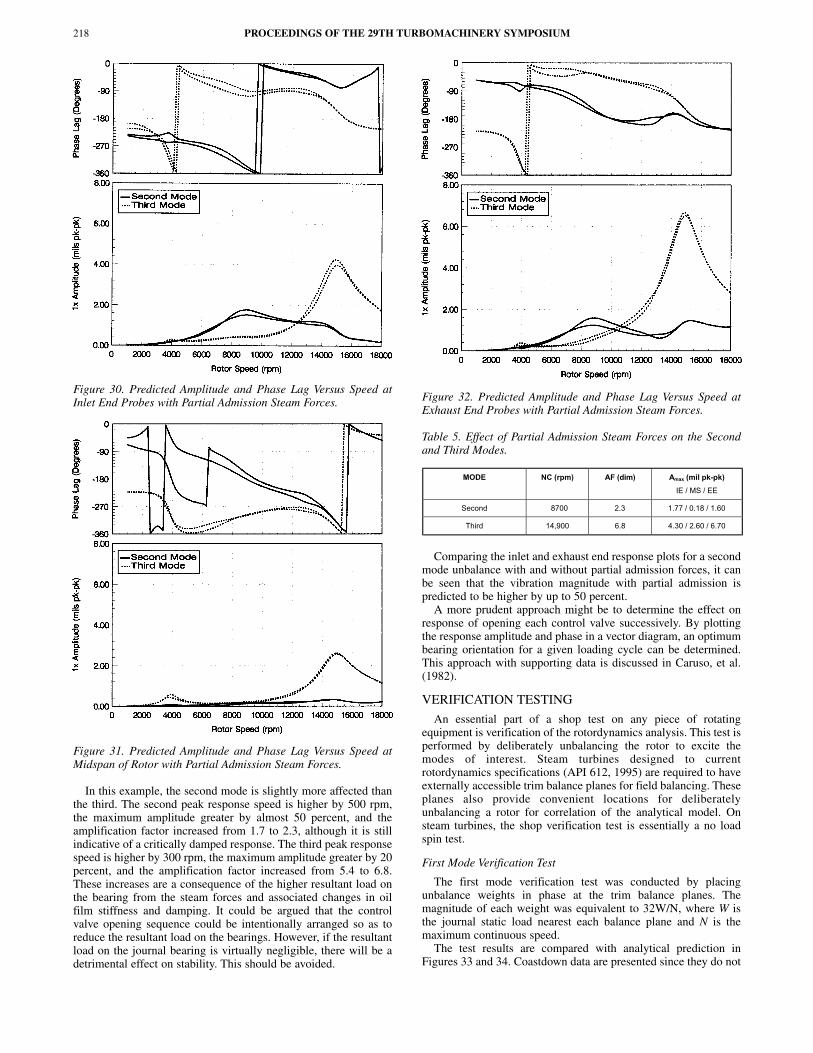
Figure 30. Predicted Amplitude and Phase Lag Versus Speed atInlet End Probes with Partial Admission Steam Forces.
Figure 31. Predicted Amplitude and Phase Lag Versus Speed atMidspan of Rotor with Partial Admission Steam Forces.
In this example, the second mode is slightly more affected thanthe third. The second peak response speed is higher by 500 rpm,the maximum amplitude greater by almost 50 percent, and theamplification factor increased from 1.7 to 2.3, although it is stillindicative of a critically damped response. The third peak responsespeed is higher by 300 rpm, the maximum amplitude greater by 20percent, and the amplification factor increased from 5.4 to 6.8.These increases are a consequence of the higher resultant load onthe bearing from the steam forces and associated changes in oilfilm stiffness and damping. It could be argued that the controlvalve opening sequence could be intentionally arranged so as toreduce the resultant load on the bearings. However, if the resultantload on the journal bearing is virtually negligible, there will be adetrimental effect on stability. This should be avoided.
Figure 32. Predicted Amplitude and Phase Lag Versus Speed atExhaust End Probes with Partial Admission Steam Forces.
Table 5. Effect of Partial Admission Steam Forces on the Secondand Third Modes.
Comparing the inlet and exhaust end response plots for a secondmode unbalance with and without partial admission forces, it canbe seen that the vibration magnitude with partial admission ispredicted to be higher by up to 50 percent.
A more prudent approach might be to determine the effect onresponse of opening each control valve successively. By plottingthe response amplitude and phase in a vector diagram, an optimumbearing orientation for a given loading cycle can be determined.This approach with supporting data is discussed in Caruso, et al.(1982).
VERIFICATION TESTING
An essential part of a shop test on any piece of rotatingequipment is verification of the rotordynamics analysis. This test isperformed by deliberately unbalancing the rotor to excite themodes of interest. Steam turbines designed to currentrotordynamics specifications (API 612, 1995) are required to haveexternally accessible trim balance planes for field balancing. Theseplanes also provide convenient locations for deliberatelyunbalancing a rotor for correlation of the analytical model. Onsteam turbines, the shop verification test is essentially a no loadspin test.
First Mode Verification Test
The first mode verification test was conducted by placingunbalance weights in phase at the trim balance planes. Themagnitude of each weight was equivalent to 32W/N, where W isthe journal static load nearest each balance plane and N is themaximum continuous speed.
The test results are compared with analytical prediction inFigures 33 and 34. Coastdown data are presented since they do not
PROCEEDINGS OF THE 29TH TURBOMACHINERY SYMPOSIUM218
MODE NC (rpm) AF (dim) Amax (mil pk-pk)
IE / MS / EE
Second 8700 2.3 1.77 / 0.18 / 1.60
Third 14,900 6.8 4.30 / 2.60 / 6.70

DESIGNING HIGH PERFORMANCE STEAM TURBINES WITH ROTORDYNAMICS AS A PRIME CONSIDERATION 219
include any influence from steam forces. The influence of anyresidual unbalance inherent in the rotor has been vectoriallysubtracted out from the data as described by Nicholas, et al. (1997).The results are compared with analytical prediction in Table 6 interms of the location, amplification factor, and maximumamplitude of the peak response. Although the locations of peakresponse speed are low by 400 rpm, or roughly 10 percent, thegeneral shape of the response trends is in good agreement. Themeasured amplification factors are approximately 25 percent highand low at the inlet and exhaust end probes, respectively, and thepeak response amplitudes low by up to 35 percent. Responsetroughs at roughly 9000 rpm also are observed in both thepredicted and measured results.
Figure 33. Measured Amplitude and Phase Lag Versus Speed atInlet End Right Probe—First Mode Unbalance Test.
Figure 34. Measured Amplitude and Phase Lag Versus Speed atExhaust End Right Probe—First Mode Unbalance Test.
Table 6. Measured Versus Predicted First Mode Peak Response—Synchronous Filtered.
Second Mode Verification Test
The second mode verification test was conducted using the sameunbalance weights as for the first mode, but placed 180 degreesout-of-phase. Coastdown test results with residual subtraction arecompared in Figures 35 and 36, and in Table 7 at the peakresponse. The results are again in good correlation, with thegeneral response shapes in excellent agreement. The difference inlocation of both peak response speeds is less than 2.5 percent, withcritically damped amplification factors.
Figure 35. Measured Amplitude and Phase Lag Versus Speed atInlet End Right Probe—Second Mode Unbalance Test.
As-Balanced Test
Coastdown plots of the rotor as-balanced are given in Figures 37and 38. Included on the figures are the response trends from bothprobes at each end of the machine. At the inlet end, the responsetrends are near equal as would be expected with a four-pad bearing,with the synchronous vibration levels all less than 0.4 mil peak-to-peak from zero to trip. At the exhaust end, however, there is somedeviation in vibration magnitude at speeds above 7000 rpm, withthe highest level less than 0.5 mil peak-to-peak. This deviation ismost likely due to some asymmetry in the stiffness of the supportstructure. Furthermore, the second mode response as predicted iswell damped. There is possibly a slight indication that the thirdmode response is being approached at the exhaust end, althoughthis peak clearly would be well above trip speed.
Journal and thrust bearing temperature data at the maximumcontinuous and trip speeds of 10,601 and 11,530 rpm are comparedwith prediction in Table 8. In this solo or no load test condition, themeasured journal pad temperatures are in good agreement withthose predicted, with the predicted values consistently higher by upto 5°F. The close agreement between both sets of adjacent pad
Inlet End Right Probe Exhaust End Right Probe
NC1
(rpm)
AF1
(dim)
AMAX
(mil pk-pk)
NC1
(rpm)
AF1
(dim)
AMAX
(mil pk-pk)
Measured 3336 3.6 0.32 3336 2.1 0.29
Predicted 3700 2.8 0.43 3700 2.8 0.46

Figure 36. Measured Amplitude and Phase Lag Versus Speed atExhaust End Right Probe—Second Mode Unbalance Test.
Table 7. Measured Versus Predicted Second Mode PeakResponse—Synchronous Filtered.
Figure 37. Measured Amplitude and Phase Lag Versus Speed atInlet End Right Probe—As-Balanced Test.
Figure 38. Measured Amplitude and Phase Lag Versus Speed atExhaust End Right Probe—As-Balanced Test.
temperatures should be expected since in a solo condition thebearing load is directed almost purely between the two lower halfpads. The observed difference of less than 5°F in both the predictedand measured temperatures is primarily due to the influence of hotoil carry over on the pad located in the downstream or with rotationlocation.
Table 8. Shop Versus Predicted Bearing Temperature Data—NoEffect of Partial Admission Steam Forces.
The measured thrust temperatures are indicative of a well-aligned bearing with the variation between the three instrumentedshoes less than 3°F. The measured values although higher, alsoagree very closely with those predicted. Since there is nominallyno load on the thrust bearing in this solo condition, the predictedvalues were calculated by assuming that the bearing was operatingat the mid float position, that is with a pivot film thickness of one-half the total thrust clearance. This assumption is likely the reasonfor the predicted values being slightly lower than those measured.
The lubricating oil inlet temperature during the shop tests was at120°F. The predicted bearing temperature values were calculatedby the bearing manufacturer (DeCamillo, 2000).
FIELD EXPERIENCE
Operating information from the field is limited to steady-statedata. Transient data were not available. Table 9 contains directunfiltered operating vibration amplitudes at six different speeds.Predicted journal and thrust bearing temperatures are comparedwith field data in Table 10 at five different operating speeds. Thepredicted values are calculated at the design operating conditionsand include the effects of partial admission steam forces and axialthrust.
PROCEEDINGS OF THE 29TH TURBOMACHINERY SYMPOSIUM220
Inlet End Right Probe Exhaust End Right Probe
NC2
(rpm)
AF2
(dim)
AMAX
(mil pk-pk)
NC2
(rpm)
AF2
(dim)
AMAX
(mil pk-pk)
Measured 8443 - 1.05 8086 2.3 0.57
Predicted 8505 - 1.01 8200 1.7 0.86
Inlet Journal Bearing
(Shop / Predicted)
Exhaust Journal Bearing
(Shop / Predicted)
Active Side Thrust Bearing
(Shop / Predicted)
Speed
(rpm)
Left (°F) Right (°F) Left (°F) Right (°F) (°F) (°F) (°F)
10601 170 / 171 173 / 176 170 / 173 175 / 178 173 / 172 177 / 172 176 / 172
11530 173 / 175 175 / 180 174 / 177 178 / 181 188 / 183 191 / 183 191 / 183

DESIGNING HIGH PERFORMANCE STEAM TURBINES WITH ROTORDYNAMICS AS A PRIME CONSIDERATION 221
Table 9. Field Vibration Amplitudes—Direct Unfiltered.
Table 10. Field Versus Predicted Bearing Temperature Data—Includes Effect of Partial Admission Steam Forces.
The difference in the operating vibration amplitude at the twoorthogonal probes per end (which are 45 degrees either side of topdead center) is indicative that the response orbit is elliptical. Thisis consistent with the theory, which predicted that in the presenceof partial admission forces the resultant load on each bearingwould be directed more heavily on one pad thus yieldingasymmetric stiffness and damping coefficients. The fact that thevibration magnitude is higher than observed during the no loadfactory test also is consistent with theory. For example, in a secondmode unbalance condition, the peak response amplitude ispredicted to be higher by roughly 38 percent at the inlet probes and48 percent at the exhaust end probes in the presence of partialadmission forces (refer to Tables 1 and 5). Note, in comparing thevibration amplitudes from Table 9 with the response curves inFigures 37 and 38, the values in the table are direct unfiltered andin the figures synchronously filtered.
The journal bearing temperature data are consistent with thevibration trends, with the pad located in the rotation positionnoticeably hotter than that opposite rotation. Furthermore, the fieldtrends are in fairly good agreement with those predicted in thatthere is some divergence in temperature between the two loadedpads. This is due to a combination of both a higher resultant loadand the influence of hot oil carry over on the pad located in therotation position. The predicted values, however, are as much as15°F lower than those measured. This is most likely due to someinaccuracy in the calculation of the partial admission steam forces.
The small difference of less than 6°F between the measuredactive side thrust temperatures is indicative that under load thebearing is operating well aligned. This implies that the self levelingbearing case also is aligned and operating as designed without anyexcessive pitching. Furthermore, the measured temperatures are infairly good agreement with those predicted, being consistently lowby 10°F or less.
The lubricating oil inlet temperature in the field is 130°F. Thepredicted temperature values were again supplied by the bearingmanufacturer (DeCamillo, 2000).
SUMMARY AND CONCLUSIONS
The increasing speed and power demands of mechanical drivesteam turbines require more sophisticated analytical tools to
accurately predict performance. Not least does this includerotordynamics analysis, particularly when applied to machines thatare designed to operate on or near lateral peak response speeds. Insuch cases, the importance of considering external operationalinfluences, such as from steam partial admission and aerodynamicexcitation forces as well as support stiffness effects cannot beoverlooked.
The case study discussed reviews the rotordynamics analysismethodology employed in the design of a critical service steamturbine driver. Steam turbines that drive synthesis gas compressorsare the most sophisticated designs in the industry. The steamturbine reviewed herein was the culmination of a design evolutionand field experience stretching over several decades. Computer-aided techniques, extensive shop testing, and improvedmanufacturing processes were all key factors in producing thisstate-of-the-art design. In particular, the ongoing refinement andconsideration of the rotor’s dynamic characteristics from conceptto final design resulted in:
• Rotor design in which the API defined critical speeds wereplaced as far away from the operating range as possible whilemaintaining efficient staging for the application.
• Highly damped first and critically damped second rotor peakresponse speeds, with the third well above trip speed.
• Insensitive rotorbearing design with minimal sensitivity tounbalance at the second peak response speed allowing operation onor near it.
• Rotor response characteristics that were carefully tuned inrelation to the operating range of the application.
• Integral coupling flange reduced moment shaft end design tominimize response sensitivity to overhung unbalance.
• Optimized bearing performance through the application of highefficiency leading edge groove bearings.
• Consideration of the destabilizing forces of labyrinth seals andblade tip clearance leakage on rotor stability.
• Evaluation of the effect of partial admission steam forces onsteady-state bearing performance and rotor response.
• A sequential method of assembly and low speed balancing therotor to ensure smooth operation at speed from zero to trip.
• Inclusion of two field trim balance planes and a turning gear.
This careful consideration of the rotor’s dynamic characteristicsthroughout the design was confirmed on the test stand asdemonstrated by:
• Excellent correlation of the analytical model through first andsecond mode unbalance testing.
• A critically damped, or nonresponsive, second mode with thethird well above trip speed.
• A highly damped lateral rotorbearing design with synchronouslyfiltered vibration levels from zero to trip speed of less than 0.5 milpeak-to-peak.
And verified in the field as demonstrated by:
• Low vibration amplitudes over the normal operating speed rangeof overall (unfiltered) value less than 1.0 mil peak-to-peak.
• Journal and thrust bearing temperatures in reasonable agreementwith predicted values with the turbine operating at load.
• Vibration and journal bearing temperature trends consistent withthose predicted in the presence of partial admission steam forces.
NOMENCLATURE
AF = Amplification factor (dim)Amax = Maximum amplitude at NC (mil peak-to-peak)
Inlet End Probes Exhaust End Probes Speed
(rpm) Left (mil pk-pk) Right (mil pk-pk) Left (mil pk-pk) Right (mil pk-pk)
8077 0.33 0.39 0.43 0.45
8550 0.45 0.49 0.45 0.51
9100 0.54 0.49 0.57 0.52
9206 0.43 0.45 0.49 0.59
9300 0.40 0.42 0.45 0.56
9891 0.61 0.84 0.72 1.02
Inlet Journal Bearing
(Field / Predicted)
Exhaust Journal Bearing
(Field / Predicted)
Active Side Thrust Bearing
(Field / Predicted)
Speed
(rpm)
Left (°F) Right (°F) Left (°F) Right (°F) (°F) (°F) (°F)
8550 185 / 174 191 / 188 182 / 175 188 / 184 201 / 211 204 / 211 203 / 211
9100 189 / 176 202 / 190 184 / 177 193 / 186 206 / 214 209 / 214 207 / 214
9206 191 / 176 204 / 190 185 / 178 196 / 187 208 / 215 212 / 215 209 / 215
9300 194 / 177 205 / 191 192 / 178 197 / 187 209 / 216 214 / 216 210 / 216
9891 193 / 179 208 / 193 189 / 181 199 / 189 211 / 220 217 / 220 213 / 220

c = Cross coupled damping coefficient (lb-sec/in)C = Direct damping coefficient (lb-sec/in)Dp = Blade pitch diameter (in)e = Synchronous precession orbit (in)EE = Exhaust end responseFex = Exhaust end bearing partial admission steam force
reaction X direction (lb)Fey = Exhaust end bearing partial admission steam force
reaction Y direction (lb)Fix = Inlet end bearing partial admission steam force reaction X
direction (lb)Fiy = Inlet end bearing partial admission steam force reaction Y
direction (lb)Fr = Radial force component (lb)Ft = Tangential force component (lb)Fx = Force in X direction (lb)Fy = Force in Y direction (lb)h = Blade height (in)HP = Stage horsepower (hp)IE = Inlet end responsek = Cross coupled stiffness coefficient (lb/in)K = Direct stiffness coefficient (lb/in)Kq = Clearance excitation cross coupled stiffness (lb/in)Kxy = Cross coupled stiffness coefficient (lb/in)Kyx = Cross coupled stiffness coefficient (lb/in)L = Bearing span (in)Le = Length from inlet end bearing to extraction control stage (in)Li = Length from inlet end bearing to inlet control stage (lb)MS = Midspan responseN = Shaft speed (rpm)NC = Peak response speed (rpm)Ve = Extraction control stage partial admission force vector (lb)Vi = Inlet control stage partial admission force vector (lb)β = Empirical adjustment factor, typically assumed to be 1.0
(dim)θe = Angle from X direction to extraction control stage force
vector (deg)θi = Angle from X direction to inlet control stage force vector
(deg)ω = Shaft speed (rad/sec)
REFERENCES
Alford, J., 1965, “Protecting Turbomachinery from Self-ExcitedRotor Whirl,” Transactions of the ASME, Journal ofEngineering for Power, 87.
API Standard 612, 1995, “Special Purpose Steam Turbines forRefinery Services,” Fourth Edition, American PetroleumInstitute, Washington D.C.
API Standard 670, 1990, “Special Purpose Couplings for RefineryServices,” Second Edition, American Petroleum Institute,Washington D.C.
API Standard 671, 1993, “Vibration, Axial Position, and BearingTemperature Monitoring Systems,” Third Edition, AmericanPetroleum Institute, Washington D.C.
Barrett, L. E., Nicholas, J. C., and Dhar, D., 1986, “The DynamicsAnalysis of Rotor Bearing Systems Using ExperimentalBearing Support Compliance Data,” Proceedings of the FourthInternational Modal Analysis Conference, Union College,Schenectady, New York.
Bethel, L. L., Gans, B. E., Brown, R. N., and Lewis, R. A., 1993,“Critical Speeds and the Importance of Stiffness—A CaseStudy in the Design and Testing of a Large Mechanical DriveSteam Turbine to API Standard 612,” Proceedings of theTwenty-Second Turbomachinery Symposium, TurbomachineryLaboratory, Texas A&M University, College Station, Texas,pp. 73-80.
Caruso, W. J., 1958, “Prediction of Critical Speeds of SteamTurbines by Dynamic Stiffness Method,” Colloquial onMechanical Impedance Methods of Mechanical Vibration,American Society of Mechanical Engineers.
Caruso, W. J., Gans, B. E., and Catlow, W. G., 1982, “Applicationof Recent Rotor Dynamics Developments to Mechanical DriveTurbines,” Proceedings of the Eleventh TurbomachinerySymposium, Turbomachinery Laboratory, Texas A&M Univer-sity, College Station, Texas, pp. 1-18.
Childs, D. W., 1993, Turbomachinery Rotordynamics—Phenomena, Modeling, and Analysis, New York, New York:John Wiley and Sons, Inc.
Childs, D. W. and Scharrer, J. K., 1986, “ExperimentalRotordynamic Coefficient Results for Teeth-on-Rotor andTeeth-on-Stator Labyrinth Gas Seals,” Transactions of theAMSE, Journal of Engineering for Gas Turbines and Power,108.
Childs, D. W. and Vance, J. M., 1997, “Annular Gas Seals andRotordynamics of Compressors and Turbines,” Proceedings ofthe Twenty-Sixth Turbomachinery Symposium, Turbomachin-ery Laboratory, Texas A&M University, College Station,Texas, pp. 201-220.
Coleman, G. M., 1958, “Methods for the Measurement ofMechanical Impedance,” Colloquial on Mechanical ImpedanceMethods of Mechanical Vibration, American Society ofMechanical Engineers.
DeCamillo, S. M., 2000, Private Communication—Journal andThrust Bearing Temperature Data.
Edney, S. L., 1995, “Pad Temperature in High Speed, LightlyLoaded Tilting Pad Journal Bearings,” Proceedings of theTwenty-Fourth Turbomachinery Symposium, TurbomachineryLaboratory, Texas A&M University, College Station, Texas,pp. 73-84.
Edney, S. L. and Mellinger, F. P., 1997, “Advances in Tilting PadJournal Bearing Design,” Dresser-Rand Technology Confer-ence, Corning, New York.
Ewins, D. J., 1984, Modal Testing: Theory and Practice,Letchworth, Hertfordshire, England: Research Studies Press.
Greathead, S. and Bostow, P., 1976, “Investigations into LoadDependent Vibrations of the High Pressure Rotor on LargeTurbo-Generators,” Proceedings of the Institution ofMechanical Engineers Conference on Vibrations in RotatingMachinery, Cambridge, England.
Haq, I. U., Kumar, C. V., and Al-Zaid, R. M., 1998, “Identificationof the Intermittent Synchronous Instability in a HighPerformance Steam Turbine Rotor Due to DeterioratedLabyrinth Seals,” American Society of Mechanical Engineers,98-GT-305.
Iwatsubo, T., 1980, “Evaluation of Instability Forces of LabyrinthSeals in Turbines or Compressors,” Rotordynamic InstabilityProblems in High Performance Turbomachinery, NASA CPNo. 2133, Proceedings of a Workshop Held at Texas A&MUniversity.
Kurohashi, T., Inoue, Y., Abe, T., and Fujikawa, T., 1980, “Springand Damping Coefficients of the Labyrinth Seals,” Paper No.C283/80, Proceedings of the Second Institution of MechanicalEngineers Conference on Vibrations in Rotating Machinery,Cambridge, England.
Leie, B. and Thomas, H., 1980, “Self-Excited Rotor Whirl Due toTip-Seal Leakage Forces,” Rotordynamic Instability Problemsin High Performance Turbomachinery, NASA CP No. 2133,Proceedings of a Workshop held at Texas A&M University.
PROCEEDINGS OF THE 29TH TURBOMACHINERY SYMPOSIUM222

DESIGNING HIGH PERFORMANCE STEAM TURBINES WITH ROTORDYNAMICS AS A PRIME CONSIDERATION 223
Mikula, A. and Gregory, R., 1981, “A Comparison of ThrustBearing Lubricant Supply Methods,” ASME Journal ofLubrication Technology, 105.
Mancuso, J. R., Gibbons, C. B., and Munyon, R. E., 1989, “TheApplication of Flexible Couplings for Turbomachinery,”Proceedings of the Eighteenth Turbomachinery Symposium,Turbomachinery Laboratory, Texas A&M University, CollegeStation, Texas, pp. 141-168.
Nicholas, J. C., 1989, “Operating Turbomachinery On or Near theSecond Critical Speed in Accordance with API Specifications,”Proceedings of the Eighteenth Turbomachinery Symposium,Turbomachinery Laboratory, Texas A&M University, CollegeStation, Texas, pp. 47-54.
Nicholas, J. C. and Barrett, L. E., 1986, “The Effect of BearingSupport Flexibility on Critical Speed Prediction,” ASLETransactions, 29, (3).
Nicholas, J. C., Edney S. L., Kocur, J. A., and Hustak, J. F., 1997,“Subtracting Residual Unbalance for Improved Test StandVibration Correlation,” Proceedings of the Twenty-SixthTurbomachinery Symposium, Turbomachinery Laboratory,Texas A&M University, College Station, Texas, pp. 7-18.
Nicholas, J. C., Whalen, J. K., and Franklin, S. D., 1986,“Improving Critical Speed Calculations Using FlexibleBearing Support FRF Compliance Data,” Proceedings of theFifteenth Turbomachinery Symposium, TurbomachineryLaboratory, Texas A&M University, College Station, Texas,pp. 69-78.
Pollman, E. and Termuehlen, H., 1975, “Turbine Rotor VibrationsExcited by Steam Forces,” ASME Paper 75-WA/Pwr-11.
Scharrer, J. K. and Pelletti, J. M., 1995, “Leakage andRotordynamic Effects of Compressible Annular Seals,”Proceedings of the Twenty-Fourth Turbomachinery Sympo-sium, Turbomachinery Laboratory, Texas A&M University,College Station, Texas, pp.175-190.
Singh, M. P., Vargo, J. J., Schiffer, D. M., and Dello, J. D., 1988,“SAFE Diagram—A Design and Reliability Tool for TurbineBlading,” Proceedings of the Seventeenth TurbomachinerySymposium, Turbomachinery Laboratory, Texas A&M Univer-sity, College Station, Texas, pp. 93-102.
Sohre, J. S., 1975, “Steam Turbine Blade Failures, Causes andCorrection,” Proceedings of the Fourth TurbomachinerySymposium, Turbomachinery Laboratory, Texas A&M Univer-sity, College Station, Texas, pp. 9-30.
Thomas, H., 1958, “Instabile Eigenschwingungen vonTurbinenläufern, Angefacht durch die Spaltströmungen,Stopfbüchsen und Beschaufelungen,” Bull de L’AIM, 71.
Urlichs, K., 1976, “Die Spaltströmung bei Thermischen Turbo-Machinen als Ursache für die Entstehung Schwingungsan-facher Querkräfte,” Ingenieur-Archiv, 45.
Williams, B. P. and Flack, R. D., 1993, “The Calculation ofRotordynamic Coefficients for Labyrinth Seals—A Manual forthe Computer Program LABY3,” ROMAC Report No. 344,University of Virginia.

PROCEEDINGS OF THE 29TH TURBOMACHINERY SYMPOSIUM224