Designing High-Performance and Power Efficient 3-Phase...
11
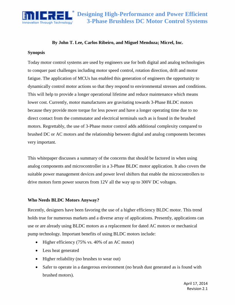
Designing High-Performance and Power Efficient 3-Phase Brushless DC Motor Control Systems April 17, 2014 Revision 2.1 By John T. Lee, Carlos Ribeiro, and Miguel Mendoza; Micrel, Inc. Synopsis Today motor control systems are used by engineers use for both digital and analog technologies to conquer past challenges including motor speed control, rotation direction, drift and motor fatigue. The application of MCUs has enabled this generation of engineers the opportunity to dynamically control motor actions so that they respond to environmental stresses and conditions. This will help to provide a longer operational lifetime and reduce maintenance which means lower cost. Currently, motor manufactures are gravitating towards 3-Phase BLDC motors because they provide more torque for less power and have a longer operating time due to no direct contact from the commutator and electrical terminals such as is found in the brushed motors. Regrettably, the use of 3-Phase motor control adds additional complexity compared to brushed DC or AC motors and the relationship between digital and analog components becomes very important. This whitepaper discusses a summary of the concerns that should be factored in when using analog components and microcontroller in a 3-Phase BLDC motor application. It also covers the suitable power management devices and power level shifters that enable the microcontrollers to drive motors form power sources from 12V all the way up to 300V DC voltages. Who Needs BLDC Motors Anyway? Recently, designers have been favoring the use of a higher efficiency BLDC motor. This trend holds true for numerous markets and a diverse array of applications. Presently, applications can use or are already using BLDC motors as a replacement for dated AC motors or mechanical pump technology. Important benefits of using BLDC motors include: Higher efficiency (75% vs. 40% of an AC motor) Less heat generated Higher reliability (no brushes to wear out) Safer to operate in a dangerous environment (no brush dust generated as is found with brushed motors).
Transcript of Designing High-Performance and Power Efficient 3-Phase...
Designing High-Performance and Power Efficient
3-Phase Brushless DC Motor Control Systems
April 17, 2014 Revision 2.1
By John T. Lee, Carlos Ribeiro, and Miguel Mendoza; Micrel, Inc.
Synopsis
Today motor control systems are used by engineers use for both digital and analog technologies
to conquer past challenges including motor speed control, rotation direction, drift and motor
fatigue. The application of MCUs has enabled this generation of engineers the opportunity to
dynamically control motor actions so that they respond to environmental stresses and conditions.
This will help to provide a longer operational lifetime and reduce maintenance which means
lower cost. Currently, motor manufactures are gravitating towards 3-Phase BLDC motors
because they provide more torque for less power and have a longer operating time due to no
direct contact from the commutator and electrical terminals such as is found in the brushed
motors. Regrettably, the use of 3-Phase motor control adds additional complexity compared to
brushed DC or AC motors and the relationship between digital and analog components becomes
very important.
This whitepaper discusses a summary of the concerns that should be factored in when using
analog components and microcontroller in a 3-Phase BLDC motor application. It also covers the
suitable power management devices and power level shifters that enable the microcontrollers to
drive motors form power sources from 12V all the way up to 300V DC voltages.
Who Needs BLDC Motors Anyway?
Recently, designers have been favoring the use of a higher efficiency BLDC motor. This trend
holds true for numerous markets and a diverse array of applications. Presently, applications can
use or are already using BLDC motors as a replacement for dated AC motors or mechanical
pump technology. Important benefits of using BLDC motors include:
Higher efficiency (75% vs. 40% of an AC motor)
Less heat generated
Higher reliability (no brushes to wear out)
Safer to operate in a dangerous environment (no brush dust generated as is found with
brushed motors).
Designing High-Performance and Power Efficient
3-Phase Brushless DC Motor Control Systems
April 17, 2014 Revision 2.1
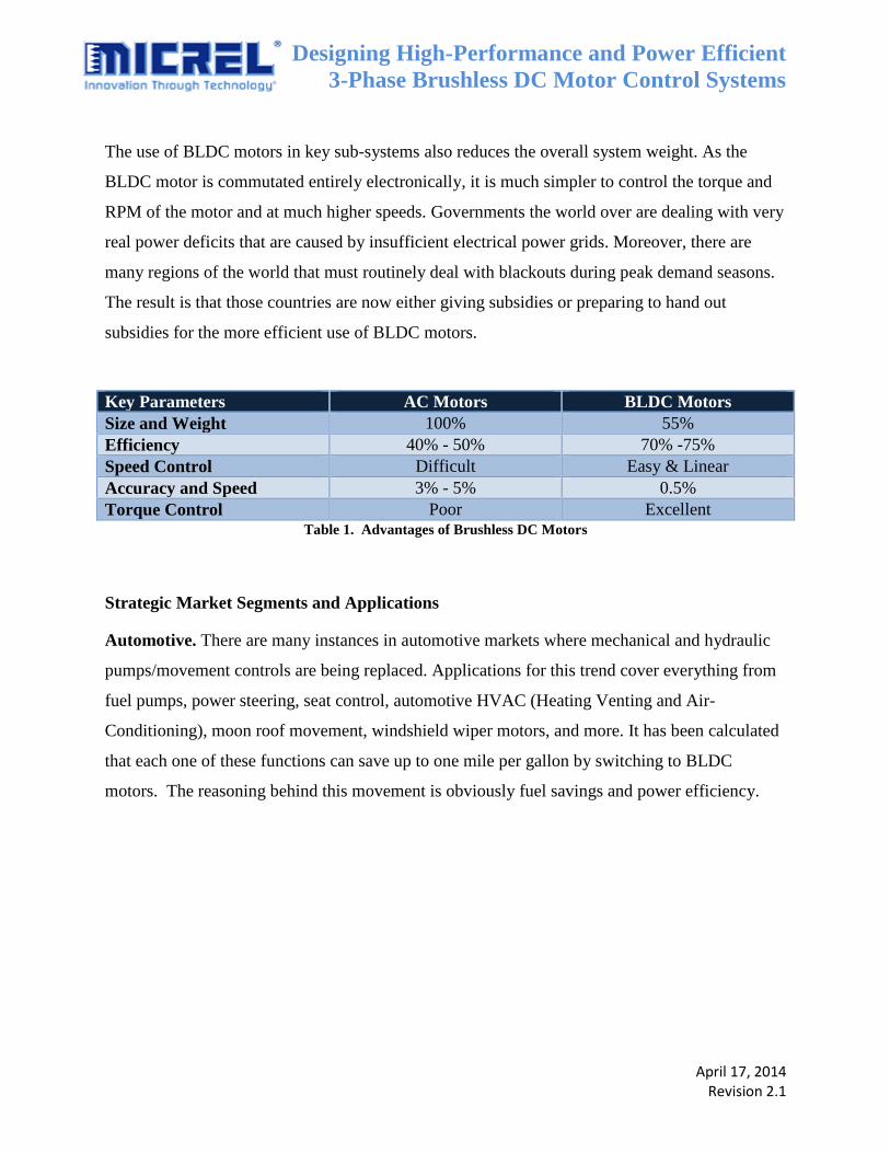
The use of BLDC motors in key sub-systems also reduces the overall system weight. As the
BLDC motor is commutated entirely electronically, it is much simpler to control the torque and
RPM of the motor and at much higher speeds. Governments the world over are dealing with very
real power deficits that are caused by insufficient electrical power grids. Moreover, there are
many regions of the world that must routinely deal with blackouts during peak demand seasons.
The result is that those countries are now either giving subsidies or preparing to hand out
subsidies for the more efficient use of BLDC motors.
Key Parameters AC Motors BLDC Motors
Size and Weight 100% 55%
Efficiency 40% - 50% 70% -75%
Speed Control Difficult Easy & Linear
Accuracy and Speed 3% - 5% 0.5%
Torque Control Poor Excellent Table 1. Advantages of Brushless DC Motors
Strategic Market Segments and Applications
Automotive. There are many instances in automotive markets where mechanical and hydraulic
pumps/movement controls are being replaced. Applications for this trend cover everything from
fuel pumps, power steering, seat control, automotive HVAC (Heating Venting and Air-
Conditioning), moon roof movement, windshield wiper motors, and more. It has been calculated
that each one of these functions can save up to one mile per gallon by switching to BLDC
motors. The reasoning behind this movement is obviously fuel savings and power efficiency.
Designing High-Performance and Power Efficient
3-Phase Brushless DC Motor Control Systems
April 17, 2014 Revision 2.1
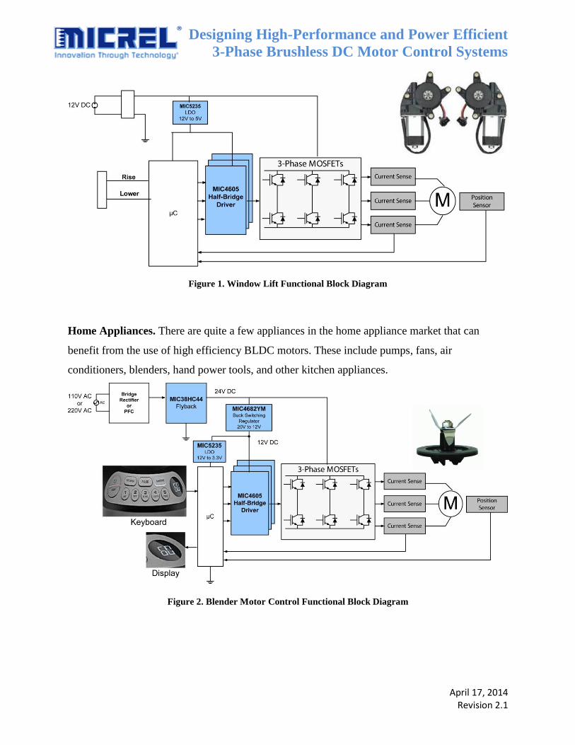
Figure 1. Window Lift Functional Block Diagram
Home Appliances. There are quite a few appliances in the home appliance market that can
benefit from the use of high efficiency BLDC motors. These include pumps, fans, air
conditioners, blenders, hand power tools, and other kitchen appliances.
Figure 2. Blender Motor Control Functional Block Diagram

Designing High-Performance and Power Efficient
3-Phase Brushless DC Motor Control Systems
April 17, 2014 Revision 2.1
Industrial Systems. Most pumps, fans, air conditioners, mixers, and HVAC units require a
motor drive. The EU has issued an edict that requires all new industrial appliances to use the 3-
Phase “Inverter Drive” of the BLDC motors.
Figure 3. Air Conditioning Functional Block Diagram

Designing High-Performance and Power Efficient
3-Phase Brushless DC Motor Control Systems
April 17, 2014 Revision 2.1
White Goods. The electricity use in many clothes washers and dryers can be reduced with the
adoption of higher efficiency BLDC motors.
Figure 4. Washer Motor Functional Diagram
Segments Driving Force Applications
Automotive Fuel Savings
Higher Efficiency and Reliability
Electrical Pumps
Power Steering
Wipers
White Goods EU-Drive Towards Clean Energy
and Power Efficiency
Washers
Dryers
Refrigerators
Air Conditioning
Industrial EU-“Inverter Drive” Power Efficiency Pump
Fans
Heaters
Home Appliance Clean Energy and Power Efficiency
Government Subsidy
Blenders
Refrigerators
HVAC Table 2. Key Areas for Brushless DC Motor Drives

Designing High-Performance and Power Efficient
3-Phase Brushless DC Motor Control Systems
April 17, 2014 Revision 2.1
What Drives BLDC Motors?
There are several methods for driving a BLDC motor. Some fundamental system requirements
are listed below:
a. Power Transistors. These are usually MOSFETs or IGBTs that can tolerate high
voltages (matched to the requirements of the motor). Most home appliances use motors
that produce half to three quarter of a horsepower (1hp = 734W). Hence, typical current
capabilities of up to 10A are utilized. For a high voltage system (>350V typically),
IGBTS can be used.
b. MOSFET/IGBT Drivers. Generally, a set of MOSFET or IGBT drivers are utilized.
One could choose either three “Half Bridge” drivers or 3-Phase drivers. These solutions
must be able to handle two times the motor voltage to manage the back-electromotive
force (EMF) generated from the motors. Moreover, these drivers should provide
protection of the power transistors via timing and switching controls that ensure the top
transistors are turned off before the bottom transistors turn on.
c. Feedback Elements/Control. Designers should have some sort of feedback element in
all servo control systems. Examples include optical sensors, hall effect sensors,
tachometers, and sensorless EMF sense—the least costly of all. Various feedback
methods are useful, depending upon the precision required, RPM, and torque needed.
Many consumer applications generally seek to use the sensorless technique of back-EMF
sense.
d. Analog to Digital Converter. In many situations, an A/D device is needed in order to
convert the analog signals to digital code, which are then sent to the system MCU.
e. MCU. All closed-loop control systems (BLDC motors are nearly always in this group)
require an MCU, which handles the servo loop control, calculations, corrections, PID
controls, and sensor management. These digital controllers are usually 16-bit, but less
sophisticated applications can use 8-bit controllers.
f. Analog Power/Regulators/References. In addition to the above-mentioned components,
many systems contain axillary power, regulation, voltage conversion, and other analog
devices such as supervisors, LDOs, DC-to-DC converters, and OP amps.

Designing High-Performance and Power Efficient
3-Phase Brushless DC Motor Control Systems
April 17, 2014 Revision 2.1
ZNEO Core MCUGain Calculations
Position and Velocity Calculations
PID Control System
Stabilty Compensation
Phase Detech
Back EMF Calculations
Sensor Management
ADC I/0s
MIC4604
Half Bridge Driver
Phase AProvide Protection and
Appropriate Voltage and
Current to Drive the
MOSFET
ON or OFF
MOSFETHigh Voltage
Switch
(ON / OFF)
MOSFET
MOSFET
MIC6270
EMF Feedback
Feedback Loop to
Detect Position,
Speed, and
Direction
MIC5235LDO
Provides Constant
Voltage Despite of
Input Voltage
Variations MIC4682
Buck RegulatorProvides Regulated
Output Voltage that
is Lower Than the
Input Voltage with
High Efficiency
24V DCAC
Bridge
Rectifier & PFCRectifies AC to DC
and Maintains the
Current in Phase with
the Voltage
MIC38HC44
Flyback Provides Regulated
Output DC Voltage
Isolated Supply
110V to
220V AC
12V DC
3V DC
MIC4604
Half Bridge Driver
Phase B
MIC4604
Half Bridge Driver
Phase C
Figure 5. Typical Functional Block Diagram of a 24V Brushless DC Motor Control
Micrel Advantages in Motor Drive
a. Power Drivers. Micrel maintains a broad line of MOSFET/IGBT drivers. Key
parameters include fast pulse delay, high peak current for gate charge/control, and up to
85V operation. Some examples include theMIC4604 family that can withstand up to 85V
of back-EMF motor voltage.
b. Voltage Reference and Supervisors. Micrel offers an extensive line of these devices
which are critical to the operations of MCU. Examples include: the MIC811, MIC2775,
and the MIC1232 voltage supervisors.
c. OP Amps/Comparators. Micrel has a line of low power op amps and comparators.
These devices are critical to the precision feedback control of servo systems. Examples
include the MIC6270, MIC841N, and the MIC833.
d. LDO. Micrel offers the broadest line of LDOs in the industry including the fastest
transient LDO, lowest input LDO, lowest dropout LDO, and highest current LDO.
Examples include the MIC49150, MIC29150, MIC5235, and the MIC5283.
e. DC-to-DC Switching Regulators. Micrel also offers an extensive line of DC-to-DC
convertors with the highest efficiencies. These are used in auxiliary power applications.
Examples include the MIC2605 Boost and MIC4682 Buck (Step-Down) switching
regulators.
Designing High-Performance and Power Efficient
3-Phase Brushless DC Motor Control Systems
April 17, 2014 Revision 2.1
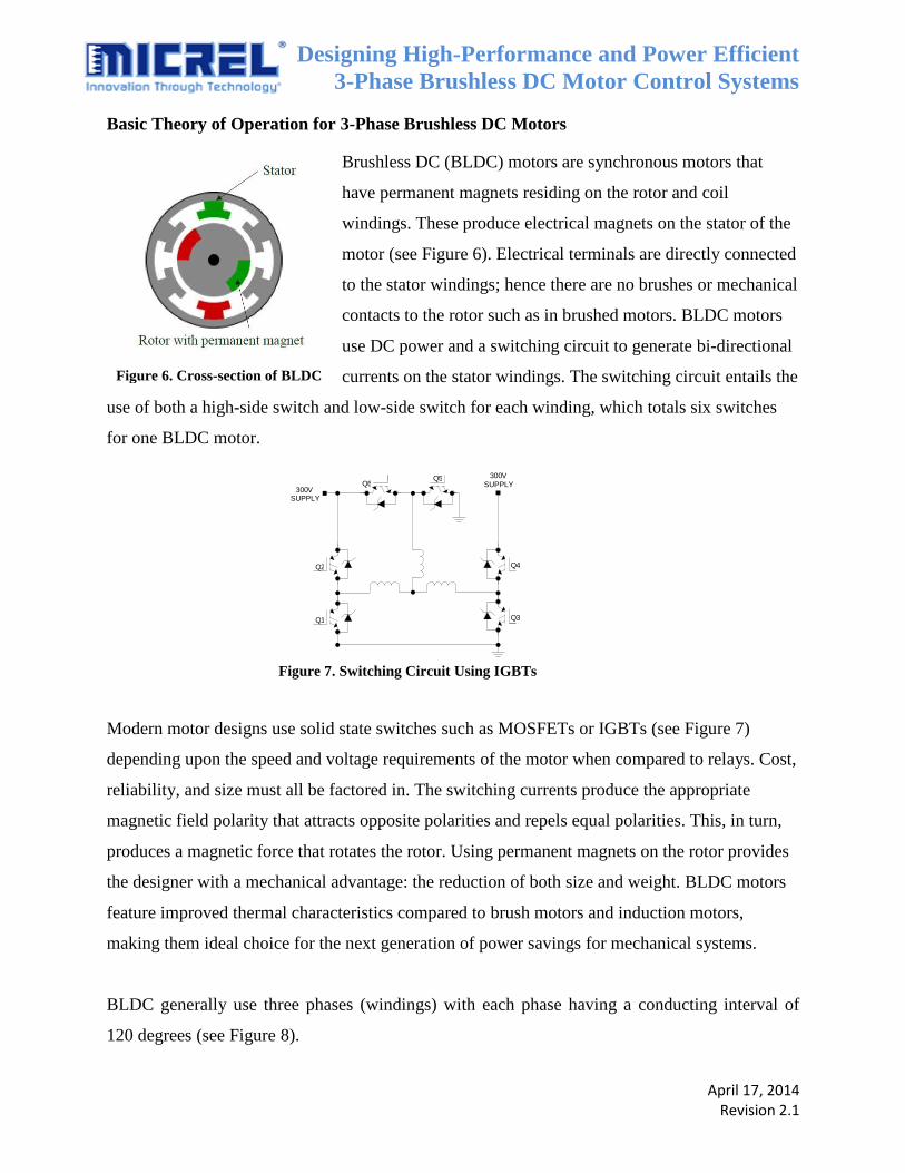
Basic Theory of Operation for 3-Phase Brushless DC Motors
Brushless DC (BLDC) motors are synchronous motors that
have permanent magnets residing on the rotor and coil
windings. These produce electrical magnets on the stator of the
motor (see Figure 6). Electrical terminals are directly connected
to the stator windings; hence there are no brushes or mechanical
contacts to the rotor such as in brushed motors. BLDC motors
use DC power and a switching circuit to generate bi-directional
currents on the stator windings. The switching circuit entails the
use of both a high-side switch and low-side switch for each winding, which totals six switches
for one BLDC motor.
Modern motor designs use solid state switches such as MOSFETs or IGBTs (see Figure 7)
depending upon the speed and voltage requirements of the motor when compared to relays. Cost,
reliability, and size must all be factored in. The switching currents produce the appropriate
magnetic field polarity that attracts opposite polarities and repels equal polarities. This, in turn,
produces a magnetic force that rotates the rotor. Using permanent magnets on the rotor provides
the designer with a mechanical advantage: the reduction of both size and weight. BLDC motors
feature improved thermal characteristics compared to brush motors and induction motors,
making them ideal choice for the next generation of power savings for mechanical systems.
BLDC generally use three phases (windings) with each phase having a conducting interval of
120 degrees (see Figure 8).
Figure 6. Cross-section of BLDC
motor
300 V SUPPLY
300 V SUPPLY
Q 1
Q 2
Q 3
Q 4
Q 6 Q 5
Figure 7. Switching Circuit Using IGBTs

Designing High-Performance and Power Efficient
3-Phase Brushless DC Motor Control Systems
April 17, 2014 Revision 2.1
Figure 3. 6 Step Commutation
A
B C
AC AB CB CA BA BC AC
A
C
B
Because the current is bi-directional, each phase has two steps per conducting interval. This is
called six-step commutation. For example, the commutation phase sequence can be AB-AC-BC-
BA-CA-CB. Each conducting stage is one step and only two windings conduct current at any
time, leaving the third winding floating. The un-energized winding can be used as a feedback
control that forms the basis for the characteristics needed for sensorless control algorithms.
To keep the magnetic field in the stator moving ahead of the rotor and to create optimal torque,
the transition from one sector to another must happen at exact rotor positions. Maximum torque
is attained via the switching circuit commutating every 60 degrees. All the switching control
algorithms are implanted in the MCU. The microcontroller can control the switching circuit
through the MOSFET drivers, which contain the appropriate response times, such as prop delays,
rise and fall times, and drive capability including the gate drive voltage and current sync required
to turn the MOSFET/IGBT to the “ON” or “OFF” state.
The rotor position is crucial in determining the correct moment to commutate the motor winding.
In applications where precision is required, hall sensors or a tachometer are used to calculate the
position, speed, and torque of the rotor. In applications where cost is the most important
consideration, the sensorless technique—which is the calculation of the back electromotive force
(EMF)—can be used to calculate position, speed, and torque.
Figure 8. Six Step Commutation
Designing High-Performance and Power Efficient
3-Phase Brushless DC Motor Control Systems
April 17, 2014 Revision 2.1
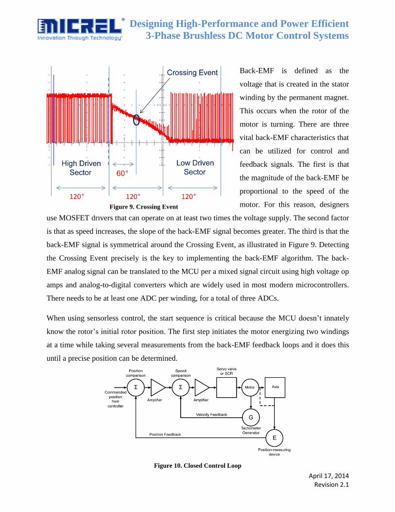
Back-EMF is defined as the
voltage that is created in the stator
winding by the permanent magnet.
This occurs when the rotor of the
motor is turning. There are three
vital back-EMF characteristics that
can be utilized for control and
feedback signals. The first is that
the magnitude of the back-EMF be
proportional to the speed of the
motor. For this reason, designers
use MOSFET drivers that can operate on at least two times the voltage supply. The second factor
is that as speed increases, the slope of the back-EMF signal becomes greater. The third is that the
back-EMF signal is symmetrical around the Crossing Event, as illustrated in Figure 9. Detecting
the Crossing Event precisely is the key to implementing the back-EMF algorithm. The back-
EMF analog signal can be translated to the MCU per a mixed signal circuit using high voltage op
amps and analog-to-digital converters which are widely used in most modern microcontrollers.
There needs to be at least one ADC per winding, for a total of three ADCs.
When using sensorless control, the start sequence is critical because the MCU doesn’t innately
know the rotor’s initial rotor position. The first step initiates the motor energizing two windings
at a time while taking several measurements from the back-EMF feedback loops and it does this
until a precise position can be determined.
Figure 10. Closed Control Loop
Figure 9. Crossing Event

Designing High-Performance and Power Efficient
3-Phase Brushless DC Motor Control Systems
April 17, 2014 Revision 2.1
BLDC motors generally operate using a closed loop control system that requires an MCU. The
MCU performs the servo loop control, calculations, corrections, PID controls, and sensor
management using back-EMF, a hall sensor, or tachometer (see Figure 10). These digital
controllers are generally 8-bits or higher and require EEPROM to store the firmware that creates
the algorithms necessary to set the desired motor speeds, direction, and to maintain motor
stability. The MCU often offers ADCs that allow for sensorless motor control architecture. This
architecture saves on valuable cost and board space. The MCU features construability and the
flexibility necessary to optimize the algorithms for the application. The analog ICs can give the
MCU efficient power supply, voltage regulation, voltage references, the ability to drive
MOSFETs or IGBTs, and fault protection. Both technologies can operate 3-Phase BLDC motors
efficiently and at a comparable price point versus induction motors and brushed motors.
Conclusion
The need to migrate towards higher efficiency BLDC motors in many markets and applications
is becoming increasingly commonplace. This is due to certain key benefits:
Higher efficiency (75% vs. 40% of an AC motor)
Lower heat generation
Higher reliability (no electrical contacts)
Safer to operate in a dangerous environment (no brush dust generated as in brushed
motors).
By using the BLDC motor in key sub-systems, the overall weight can also be reduced. This
means that the application can offer better fuel economy in vehicles. As the BLDC motor is
entirely commutated electronically, it is much easier to control the torque and RPM of the motor
and at much higher speeds. Around the world, many countries are facing insufficient power due
to electrical power grid deficiencies. To be certain, a small number of countries are now either
giving subsidies or getting ready to provide subsidies for the more efficient use of BLDC motors.
The BLDC deployment is but one of the many trends addressing the green initiative to save the
world’s precious resources without adversely impacting our way of life.