Designing a Universal GNSS Simulator for Pseudorange Calculation
7
International Journal on Recent and Innovation Trends in Computing and Communication ISSN: 2321-8169 Volume: 3 Issue: 1 382 - 388 _______________________________________________________________________________________________ 382 IJRITCC | January 2015, Available @ http://www.ijritcc.org _______________________________________________________________________________________ Designing a Universal GNSS Simulator for Pseudorange Calculation Ritwik Das 1 A. Sriram 2 Student 1 , Assistant professor 2 , Dept. of Electronics & Communication Engineering SRM Universiy, Kattankulathur Chennai, India e-mail: [email protected] e-mail: [email protected] Abstract— With the increasing number of users to G.N.S.S. services it‟s crucial to lower the time to market and cost for handheld user devices. It‟s also very important that those devices are reliable enough to be used in real time ap plication. Real time satellite signals for any G.N.S.S. systems are subject to different types of error (Signal Unavailability, Blockage, Tropospheric, Ionospheric, Multipath, etc.). G.N.S.S. simulators can be a solution to these problems. The difficulty in designing a G.N.S.S. simulator is that they have to be modelled as close to real world as possible, taking into account all types of error. The signal simulators help us achieve lower system and hardware complexity and provide us with a ready test bench for end user devices. The advantage of the simulators is that they can provide precise pseudorange even in the absence of satellite signals. The aim is to design a simulator which can simulate the satellite signals while keeping the all the errors as low as possible while keeping the G.D.O.P. in the range of 4 to 5. Keywords:- GNSS,Pseudo-range Calculation, GPS, Satellite Constellation, Error Minimization __________________________________________________*****_________________________________________________ I. INTRODUCTION Radio based navigation systems were first developed in the 1920‟s. These were used widely in World War II by the ships and planes of both sides. The drawback of using radio waves that are generated on the ground is that you must choose between a system that is very accurate but doesn‟t cover a wide area (high frequency radio waves, like UHF TV) and one that covers a wide area but is not very accurate (like AM radio). The only way to provide coverage for the entire world is to place high-frequency radio transmitters in space. The development of artificial satellites has made possible the transmission of more-precise, line-of-sight radio navigation signals and sparked a new era in navigation technology. A high-frequency radio wave can cover a large area and be very accurate (it overcomes the noise on the way to the ground by having a specially coded signal). Satellites were first used in position-finding in a simple but reliable two-dimensional Navy system called Transit. This laid the groundwork for a system that would later revolutionize navigation forever –the Global Positioning System. G.N.S.S. satellites transmit signals to equipment on the ground. G.N.S.S. receivers passively receive satellite signals; they do not transmit. G.N.S.S. receivers require an unobstructed view of the sky, so they are used only outdoors and they often do not perform well within forested areas or near tall buildings. GPS operations depend on a very accurate time reference, which is provided by atomic clocks. Each G.N.S.S. satellite has atomic clocks on board which are regularly monitored and are corrected for offset in the time using the reference clock. Each G.N.S.S. satellite transmits data that indicates its location and the current time (ephemeris). All G.N.S.S. satellites synchronize operations so that these repeating signals are transmitted at the same instant. The signals, moving at the speed of light, arrive at a GPS receiver at slightly different times because some satellites are farther away than others. Fig 1. Diagram of a typical GNSS constellation. Section 2. Of this article discusses on the theoretical background. Section 3. Presents the methodology which contains simulation and implementation procedures using MATLAB. Section 4. Provides the results and analysis. Section 5. Concludes the article with the research findings. II. THEORETICAL BACKGROUND Satellites send radio signals to the receivers which are on earth surface. Using these signals receiver calculates its location on earth. A GPS receiver needs four satellites to provide a three-dimensional (3D) fix and three satellites to provide a two-dimensional (2D) fix. A three-dimensional (3D) fix means the unit knows its latitude, longitude and altitude, while a two-dimensional (2D) fix means the unit knows only its latitude and longitude. The satellites share a
-
Upload
editor-ijritcc -
Category
Documents
-
view
16 -
download
0
description
With the increasing number of users to G.N.S.S. services it‟s crucial to lower the time to market and cost for handheld user devices. It‟s also very important that those devices are reliable enough to be used in real time application. Real time satellite signals for any G.N.S.S. systems are subject to different types of error (Signal Unavailability, Blockage, Tropospheric, Ionospheric, Multipath, etc.). G.N.S.S. simulators can be a solution to these problems. The difficulty in designing a G.N.S.S. simulator is that they have to be modelled as close to real world as possible, taking into account all types of error. The signal simulators help us achieve lower system and hardware complexity and provide us with a ready test bench for end user devices. The advantage of the simulators is that they can provide precise pseudorange even in the absence of satellite signals. The aim is to design a simulator which can simulate the satellite signals while keeping the all the errors as low as possible while keeping the G.D.O.P. in the range of 4 to 5.
Transcript of Designing a Universal GNSS Simulator for Pseudorange Calculation

International Journal on Recent and Innovation Trends in Computing and Communication ISSN: 2321-8169 Volume: 3 Issue: 1 382 - 388
_______________________________________________________________________________________________
382 IJRITCC | January 2015, Available @ http://www.ijritcc.org
_______________________________________________________________________________________
Designing a Universal GNSS Simulator for Pseudorange Calculation
Ritwik Das1
A. Sriram2
Student1, Assistant professor2,
Dept. of Electronics & Communication Engineering
SRM Universiy, Kattankulathur
Chennai, India
e-mail: [email protected]
e-mail: [email protected]
Abstract— With the increasing number of users to G.N.S.S. services it‟s crucial to lower the time to market and cost for handheld user devices.
It‟s also very important that those devices are reliable enough to be used in real time application. Real time satellite signals for any G.N.S.S.
systems are subject to different types of error (Signal Unavailability, Blockage, Tropospheric, Ionospheric, Multipath, etc.). G.N.S.S. simulators
can be a solution to these problems. The difficulty in designing a G.N.S.S. simulator is that they have to be modelled as close to real world as
possible, taking into account all types of error. The signal simulators help us achieve lower system and hardware complexity and provide us with
a ready test bench for end user devices. The advantage of the simulators is that they can provide precise pseudorange even in the absence of
satellite signals. The aim is to design a simulator which can simulate the satellite signals while keeping the all the errors as low as possible while
keeping the G.D.O.P. in the range of 4 to 5.
Keywords:- GNSS,Pseudo-range Calculation, GPS, Satellite Constellation, Error Minimization
__________________________________________________*****_________________________________________________
I. INTRODUCTION
Radio based navigation systems were first developed in the
1920‟s. These were used widely in World War II by the ships
and planes of both sides. The drawback of using radio waves
that are generated on the ground is that you must choose
between a system that is very accurate but doesn‟t cover a
wide area (high frequency radio waves, like UHF TV) and one
that covers a wide area but is not very accurate (like AM
radio). The only way to provide coverage for the entire world
is to place high-frequency radio transmitters in space. The
development of artificial satellites has made possible the
transmission of more-precise, line-of-sight radio navigation
signals and sparked a new era in navigation technology. A
high-frequency radio wave can cover a large area and be very
accurate (it overcomes the noise on the way to the ground by
having a specially coded signal). Satellites were first used in
position-finding in a simple but reliable two-dimensional Navy
system called Transit. This laid the groundwork for a system
that would later revolutionize navigation forever–the Global
Positioning System. G.N.S.S. satellites transmit signals to
equipment on the ground. G.N.S.S. receivers passively receive
satellite signals; they do not transmit. G.N.S.S. receivers
require an unobstructed view of the sky, so they are used only
outdoors and they often do not perform well within forested
areas or near tall buildings. GPS operations depend on a very
accurate time reference, which is provided by atomic clocks.
Each G.N.S.S. satellite has atomic clocks on board which are
regularly monitored and are corrected for offset in the time
using the reference clock. Each G.N.S.S. satellite transmits
data that indicates its location and the current time
(ephemeris). All G.N.S.S. satellites synchronize operations so
that these repeating signals are transmitted at the same instant.
The signals, moving at the speed of light, arrive at a GPS
receiver at slightly different times because some satellites are
farther away than others.
Fig 1. Diagram of a typical GNSS constellation.
Section 2. Of this article discusses on the theoretical
background. Section 3. Presents the methodology which
contains simulation and implementation procedures using
MATLAB. Section 4. Provides the results and analysis.
Section 5. Concludes the article with the research findings.
II. THEORETICAL BACKGROUND
Satellites send radio signals to the receivers which are on earth
surface. Using these signals receiver calculates its location on earth.
A GPS receiver needs four satellites to provide a three-dimensional
(3D) fix and three satellites to provide a two-dimensional (2D) fix. A
three-dimensional (3D) fix means the unit knows its latitude,
longitude and altitude, while a two-dimensional (2D) fix means the
unit knows only its latitude and longitude. The satellites share a
International Journal on Recent and Innovation Trends in Computing and Communication ISSN: 2321-8169 Volume: 3 Issue: 1 382 - 388
_______________________________________________________________________________________________
383 IJRITCC | January 2015, Available @ http://www.ijritcc.org
_______________________________________________________________________________________
common time system known as „GPS time‟ and transmit (broadcast) a
precise time reference as a spread spectrum signal at two frequencies
in L-Band: L1=1575,42 MHz, L2=1227,6 MHz. Two spread
spectrum codes are used: a civil coarse acquisition (C/A) code and a
military precise (P) code. L1 contains both a P band a C/A code,
while L2 contains only the P code. The accuracy of both codes is
different. The receiver of the civil code cannot decode the military P
code when the security status „Selective Availability‟ in GPS
satellites is turned on.
A. Calculating The Pseudorange
The receiver uses messages received from satellites to
determine the satellite positions and time sent. The x,
y, and z components of satellite position and the time sent are
designated as [xi, yi, zi, ti] where the subscript i denotes the satellite
and has the value 1, 2, ..., n, where n≥4 When the time of message
reception indicated by the on-board clock is , the true reception
time is where Vb is receiver's clock bias (i.e., clock
delay). The message's transit time is . Assuming the
message travelled at the speed of light , the distance travelled
is . Knowing the distance from receiver to satellite and
the satellite's position implies that the receiver is on the surface of a
sphere centred at the satellite's position with radius equal to this
distance. Thus the receiver is at or near the intersection of the
surfaces of the four or more spheres. In the ideal case of no errors, the
receiver is at the intersection of the surfaces of the spheres. The clock
error or bias, b, is the amount that the receiver's clock is off. The
receiver has four unknowns, the three components of GPS receiver
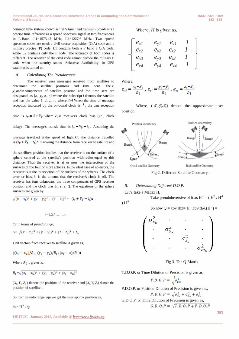
position and the clock bias [x, y, z, t]. The equations of the sphere
surfaces are given by:
= ,
i=1,2,3…….n
Or in terms of pseudorange,
ρ=
Unit vectors from receiver to satellite is given as,
, , ))
Where is given as,
=
(Xu, Yu, Zu ) denote the position of the receiver and (Xi, Yi, Zi) denote the
position of satellite i.
So from pseudo range eqn we get the user approx position as,
dx= H-1 . dρ
Where, H is given as,
ex1 ey1 ez1 1
ex2 ey2 ez2 1 ex3 ey3 ez3 1
ex4 ey4 ez4 1
Where,
exi = , eyi = , ezi =
Where, ( denote the approximate user
position.
Fig 2. Different Satellite Geomatry .
B. Determining Different D.O.P.
Let‟s take a Matrix H,
Take pseudoinversive of it as H-1 = ( HT . H-1
) H-T So now Q = cov(dx)= H-1.cov(dρ).(H-1) =
Fig 3. The Q-Matrix.
T.D.O.P. or Time Dilution of Precision is given as,
P.D.O.P. or Position Dilution of Precision is given as,
G.D.O.P. or Time Dilution of Precision is given as,

International Journal on Recent and Innovation Trends in Computing and Communication ISSN: 2321-8169 Volume: 3 Issue: 1 382 - 388
_______________________________________________________________________________________________
384 IJRITCC | January 2015, Available @ http://www.ijritcc.org
_______________________________________________________________________________________
III. METHODOLOGY
We are trying to write a code using MATLAB which is the
same as used in GPS receivers. The code will take the
distances (as inputs) send by satellites which is between the
satellite and the point. Also the code will know the position of
satellites in space.
All points with distance from satellite i, defines a sphere
in space. We also assume that earth is spherical, the
intersection of these two spheres is a circle on earth surface.
For each satellite i it‟s the same case. If we could take the
exact the distances properly then the circles formed by the
circles and earth intersect at user location. But there is a
problem, we cannot determine exactly as there is an error
term embedded. As a result of these error terms the circles
intersect with at least two points among each other. As a result
an ambiguity area is formed (fig 6.3), we know the point lies
in between that area but we don‟t know the exact point.
S1 S2
P
S3
Fig.4 The Satellite Ambiguity Area
So we will try to propose a probabilistic methodology to
estimate the location of point P and error incorporated while
doing so. When the user of GPS receiver wants the output as
lateral and longitudinal coordinates on earth, the inputs of the
receiver will be
1. Radius of the earth; r = RE (Assumption: Earth is
assumed to be spherical).
2. Place of satellite i (for i =1,…,N); αi, βi, ri in spherical
coordinates.
3. Distance between satellite i (i =1,…,N) and our
location; dio. (Taken from satellite i, by the GPS
gadget).
4. Probability distribution of di and we assume that di
has a normal pdf with µ = dio and σ = 50m.
di
. Fig 5. Expected PDF graph
We used hatch filtering to minimize the error generated in
the satellite pseudorange. Motivated by the efficiency of the
Hatch gain and the advantage of position domain filtering, the
position domain hatch filter (PDHF) for kinematic satellite
based positioning was developed. The PDHF is more robust to
changes in the visible satellite constellation during the
positioning task. The stepwise PDH filtering strategy in
MATLAB can be explained with the help of block diagram.
Fig.5- Flowchart for MATLAB code implemented for PDHF

International Journal on Recent and Innovation Trends in Computing and Communication ISSN: 2321-8169 Volume: 3 Issue: 1 382 - 388
_______________________________________________________________________________________________
385 IJRITCC | January 2015, Available @ http://www.ijritcc.org
_______________________________________________________________________________________
Fig.6 Flowchart for MATLAB code continued
Where,
1. ReadObsfile:
Reads the user observation file in RINEX format containing
pseudorange, carrier phase, time of week, satellite ID etc.
2. Rinexe:
Reads the navigation file (ephemeris file) in RINEX format.
3. GetEph:
Reshapes the navigation data into a matrix from.
4. FindEph:
Finds a proper column in ephemeris data matrix for a given
time and satellite ID.
5. CheckT:
Repairs over and underflow of GPS time.
6. Satpos:
Calculates X, Y, Z co-ordinates at time„t‟ from given
ephemeris data.
7. ECorr:
Returns the rotated satellite co-ordinates due to earth
rotation during signal travel time.
8. Topocent:
Calculates azimuth and elevation angle, given rotated
satellite co-ordinates and receiver initial position (usually
assumed as [0, 0, 0]).
9. Tmatrix:
„1‟ if satellite is present in two consecutive epochs, „0‟ if
not. 83
10. DGPScorr:
Gets differential corrections from reference receiver.
11. Bancroft:
Calculates preliminary co-ordinates (Xk) for a GPS receiver
based on pseudoranges to 4 or more satellites [17].
12. RtRange:
Calculates range from preliminary receiver co-ordinates to
rotated satellites.
13. ELOS:
Estimates line of site from the receiver to the individual
satellites and forms „H‟ matrix.
14. IniHatch:
Initializes Hatch filter, for first epoch.
15. OHMCalc:
Calculates the indirect measurement vector ∗k, utilizing
delta phase observables.
16. PDHF:
Performs time propagation and measurement update part of
IV. RESULTS AND ANALYSIS
The simulation was done using MATLAB. For the
pseudorange calculation we simulated with 2 and 5 satellite
scenarios for a known position.
0.5070.507
0.50710.5071
0.5071
0.717
0.717
0.71710
1
2
3
4
x 10-11
alphabeta
Pro
babili
ty o
f poin
ts
Fig.7 Satellite Pseudorange Using 5 Satellites

International Journal on Recent and Innovation Trends in Computing and Communication ISSN: 2321-8169 Volume: 3 Issue: 1 382 - 388
_______________________________________________________________________________________________
386 IJRITCC | January 2015, Available @ http://www.ijritcc.org
_______________________________________________________________________________________
Fig 8. Error Calculated Using 5 Satellites
As we reduced the number of satellites we saw that the
ambiguity area increased and the solution was much more
erroneous.
0.5070.507
0.50710.5071
0.5071
0.717
0.717
0.71710
2
4
6
8
x 10-5
alphabeta
Pro
babili
ty o
f poin
ts
Fig 10. Satellite Pseudorange Using 2 Satellites
Fig 11. Error Calculated Using 2 Satellites
For the error minimization using PDHF, the error corrected is
solely dependent upon the filtering duration.
Duration(seconds) Series Horizontal
Error(cm)
160 3 23
160 2 62
160 1 85
336 3 54
336 2 38
336 1 11
392 3 71
392 2 56
392 1 35
510 3 18
510 2 8
510 1 4
697 3 45
697 2 42
697 1 32
Fig 10. Table for PDHF output
The amount or length of filtering also plays an important role
in the accuracy levels obtained and the stability of the output.
Consider the period of time between 350 seconds to 500
seconds (392 seconds and 510 seconds are listed in table),
where the horizontal error reaches its maximum value and
drops down to the minimum error range. In the case of PDHF
starting at the 12th epoch, the output accuracy is less affected
by drastic variations in the approximate position estimation
from pseudoranges. The maximum error in the first case is 35
cm, in the second case the maximum is 60 cm and in the third
case it is 70 cm.
V. CONCLUSION
GNSS has been used as a stand-alone system for many land
applications that require fast and precise positioning such as
mining, and automated highway systems as well as in other
high-traffic land-based applications. However, there are
situations where GNSS by itself does not provide the desired accuracy, for example when satellite signals are blocked or
when the achievable accuracy is restricted by the geometry of
the satellite constellation. This research work has focused on
the use of redundant information provided by the GNSS
satellite in obtaining precise and reliable results in a cost
efficient manner. In current day where GNSS devices are
required and crucial in every field the need to reduce the time
to market also with devices with high accuracy is important.
Which need a ready test bench which can simulate the satellite
constellation with ease. We were able to generate precise
pseudorange while kkeping the GDOP of the system under the range 4 to 5.

International Journal on Recent and Innovation Trends in Computing and Communication ISSN: 2321-8169 Volume: 3 Issue: 1 382 - 388
_______________________________________________________________________________________________
387 IJRITCC | January 2015, Available @ http://www.ijritcc.org
_______________________________________________________________________________________
ACKNOWLEDGMENT
I would like to express the deepest appreciation to my guide, Mr. A Sriram, Assistant Professor (O.G.), who has the attitude and the substance of a genius. He continually and convincingly conveyed a spirit of adventure in regard to research and an excitement in regard to project. Without his guidance and persistent help, the project would not have been possible.
REFERENCES
[1] Tomislav Kos, Maja Botnican, “Mitigating GNSS
Propagation Error Due To Atmospheric Signal Delays”
Pomorsvo, god 23,br 2, 2009..
[2] Lin Zhao and Liang Li “An Adaptive Hatch Filter to
Minimize the Effects of Ionosphere and Multipath for
GPS Single Point Positioning” 978-1-4244-2693-
5/09/$25.00 ©2009 IEEE
[3] Mensur Omerbashich, , “Integrated INS/GPS
Navigation from Popular Perspective”Journal of Air
Transportation., vol. 7, no-1, 2002
[4] Michel; Greg Farley, Stephen J Carlson, “A New
Pseudolite Battlefield Navigation System,” 07803-
4330-1/98/$10©1998 IEEE.
[5] James Chaffel, Jonathan Able, “GDOP and Cramer
Rao Bound,” 0-7803-1435-2/94//$10©1994 IEEE
[6] KAihua Liu, Po Hu “GDOP influence on TOA and
AOA positioning system” 978-0-7695-4011-
5/10//$26©2010 IEEE.
[7] Alexandar Dolganski, Anthony Szteo, “Software
Simulation of Multiple GNSS Measurements” 978-1-
4244-3878-5/09//$25©2009 IEEE
[8] Evzeny Zemskov, Jari Nurmi, “Performance
Enhancement of Embedded Software implementations
of GNSS Navigation Algorithm,”
[9] Chih-Hung Wuh,”A Study On GDOP Approximation
Using Support Vector Machines” IEEE Transactionson
Instrumentations and Measurements,Vol60,no1, Jan
2011
[10] Yue Wang, Minzian Jhao, Jie Zhong, “Design and
Implementation of Programmable Multimode GNSS
Signal Simulator” 978-1-4244-6871-3/10//$26©2010
IEEE
[11] Marc Pollina, Olivier Desenfans “Software Designed
GNSS System Emulator” 978-1-4799-2069-
3/14/$31.00 ©2014 IEEE
[12] Géraldine Artaud, Antoine de Latour, Joël Dantepal,”
A new GNSS multi constellation simulator: NAVYS”
978-1-4244-8739-4/10/$26.00 ©2010 IEEE
[13] Silva, J.S., Peres, T.R., Freire, P., Lopes, H.” Integrated
and Cost-Effective Simulation Tool for GNSS Space
Receiver Algorithms Development” 978-1-4673-2011-
5/12/$31.00 ©2012 IEEE
[14] Glenford A. McFafalane and Joseph Skobla
“Monitotring The GPS Ephimeris Data” 978-1-4244-
2622-5/09/$25.00 ©2009 IEEE.
[15] Hui Hu, Chao Yuan, Lian Fang “Extrapolation and
Fitting Algorithms for GLONASS Satellite Orbit” 978-
0-7695-3859-4/09 $26.00 © 2009 IEEE DOI
10.1109/IITA.2009.484
[16] Jiang Ruibo “Using Fourier Series to Fit The GPS
Precise Ephemeris” 978-1-4244-7237-6/$26.00 C 2010
IEEE
[17] F. Arias, Z. Jiang, W. Lewandowski and G. Petit”
BIPM Comparison of Time Transfer Techniques” 0-
7803-9052-0/05/$20.00 © 2005 IEEE.
[18] Lan Gao, Jiangqiao Lan, Jing Jiang, Xionghua Fan
“Performance Analysis of Sequential Filter Based on
Unbiased Converted Measurements with Doppler” 978-
1-61284-276-9111/$26.00 ©2011IEEE
[19] P. Fernando D. Nunes, Member, IEEE, José M. N.
Leitão, Member, IEEE, and Fernando M. G. Sousa,
Member, IEEE “Nonlinear Filtering in GNSS
Pseudorange Dynamics Estimation Combining Code
Delay and Carrier Phase” IEEE JOURNAL OF
SELECTED TOPICS IN SIGNAL PROCESSING,
VOL. 3, NO. 4, AUGUST 2009.
[20] Bradford, W., Parkinson, “ GPS Eyewitness: The Early
Years”, GPS World, September 1994, pp. 42.
[21] Pace, Scott, et al. “ The Global Positioning System:
Assessing national Policies”, 1995.
[22] Pratt, AR.,“ The Electronics and Hardware of GPS
Receivers”, Peak Traffic Ltd, UK, January 1992.
[23] Langley, RB.,“ Why GPS Signal So Complex?”, GPS
World, vol. 1, 1990.
[24] Misra, P. and Enge, P., Global Positioning System,
Signals, Measurements and Performance, Ganga-
Jamuna Press, Massachusetts, 2001.
[25] Borre, K. and Strang, G., Linear Algebra, Geodesy, and
GPS, Wellesley-Cambridge Press, Massachusetts,
1997.
[26] Hofmann-Wellenhof, B., Lichtenegger, H. and Collins,
J., GPS Theory and Practice, Springer-Verlag, New
York, 2001.
[27] Van Diggelen, F.,“ GPS and GPS+GLONASS
RTK”,Proceeding ION GPS, 1997, pp.139-144.
[28] Cannon, M.E., Lachapelle, G. and G. Lu, “ Kinematic
Ambiguity Resolution With a High Precision C/A Code
Receiver”, Department of Geomatics Engineering The
University of Calgary, Calgary, Alberta.
[29] Borre, K. and Strang, G., Linear Algebra, Geodesy, and
GPS, Wellesley-Cambridge Press, Massachusetts,
1997.
[30] Hofmann-Wellenhof, B., Lichtenegger, H. and Collins,
J., GPS Theory and Practice, Springer-Verlag, New
York, 2001.
[31] Hatch, R.R, “ The synergism of GPS code and carrier
measurements”, Proceedings of the Third International
Geodetic Symposium on satellite Doppler Positioning,
New Mexico, 1982, pp. 1213-1232.
[32] http://home-2.worldonline.nl/ samsvl/smooth.htm
[33] Lee, H.K., Rizos, C. and Jee, G.I., “ Design of
kinematic DGPS filters with consistent error covariance
information”, IEEE Proceedings - Radar, Sonar and
Navigation, 2003.87
[34] Lee, H.K., Rizos, C. and Jee, G.I., “ Position domain
filtering and range domain filtering for carrier-
smoothed-code DGNSS: an analytical comparison”,
IEEE Proceedings - Radar, Sonar and Navigation,
International Journal on Recent and Innovation Trends in Computing and Communication ISSN: 2321-8169 Volume: 3 Issue: 1 382 - 388
_______________________________________________________________________________________________
388 IJRITCC | January 2015, Available @ http://www.ijritcc.org
_______________________________________________________________________________________
2003.
[35] http://www.netlib.org/lapack/lug/node27.html
[36] Bancroft, S., “ An Algebraic Solution of the GPS
Equations”, IEEE Trans- actions on Aerospace and
Electronic Systems, 1985.
[37] Ivan, A., Getting, “ The Global Positioning System”,
IEEE Spectrum, Vol. 30, No. 12, December 1993, pp.
36-47.
[38] http://www.land.vic.gov.au/
[39] Gao, Y.,McLellan, J.F., and Abousalem, M.A., “ GPS
Positioning Results Using Precise Satellite
Ephemerides, Clock Corrections and Ionospheric Grid
Model with JupiterTM ”, Pulsearch Navigation System,
Inc.
[40] Alkan, R.M., “ GPS-Single Point Positioning Without
Selective Availability”, Department of Geodesy and
Photogrammetry Engineering., Istanbul Technical
University, Turkey.
[41] www.aero.org/publications/GPSPRIMER
[42] Langley, R.B. and Kim, D.,“ The Multipath Divergence
Problem in GPS Carrier-Smoothed Code
Pseudoranges”, Presented at 13th Canadian Symposium
on Navigation, Canadian Aeronautical and Space
Institute, Ottawa, April 30 - may 3, 2000.
[43] Hwang, P.Y., Mcgraw, G.A. and Bader, J.R., “
Enhanced differential GPS carrier-smoothed code
processing using dual-frequency measurements”, Navi-
gation: Journal of The Institute of Navigation, 1999.
[44] Bisnath, S.B. and Langley, R.B., “ GPS Phase-
Connected, Precise Point Positioning of Low Earth
Orbiters”, Presented at GNSS, Sevilla, Spain, 8-11 May
2001.