Designed for Elevating Machinery - West of Ireland Lifts · FRENIC-Lift series of inverters for...
114
Transcript of Designed for Elevating Machinery - West of Ireland Lifts · FRENIC-Lift series of inverters for...


Designed for Elevating Machinery
Reference Manual

Copyright © 2005 Fuji Electric FA Components & Systems Co., Ltd. All rights reserved.
No part of this publication may be reproduced or copied without prior written permission from Fuji Electric FA Components & Systems Co., Ltd.
All products and company names mentioned in this manual are trademarks or registered trademarks of their respective holders.
The information contained herein is subject to change without prior notice for improvement.

i
Preface
This manual provides the roles of function codes available for the FRENIC-Lift series of inverters, their overview lists, and details of each function code. Carefully read this manual for proper use. Incorrect handling of the inverter may prevent the inverter and/or related equipment from operating correctly, shorten their lives, or cause problems.
The table below lists the other materials related to the use of the FRENIC-Lift. Read them in conjunction with this manual as necessary.
Name Material No. Description
Instruction Manual INR-SI47-1038-E
Acceptance inspection, mounting & wiring of the inverter, operation using the keypad, running the motor for a test, troubleshooting, and maintenance and inspection
Multi-function Keypad "TP-G1-CLS" Instruction Manual
INR-SI47-1092-E Items on acceptance checking, and how to install and wire the multi-function keypad, an operation guide of the keypad, and specifications
FRENIC Loader Instruction Manual INR-SI47-0903-E Overview, installation, setting-up, functions,
troubleshooting, and specifications of FRENIC Loader The materials are subject to change without notice. Be sure to obtain the latest editions for use.

ii
How this manual is organized
This manual contains Chapters 1 and 2.
Chapter 1 BLOCK DIAGRAMS FOR CONTROL LOGIC
This chapter describes the main block diagrams for the control logic of the FRENIC-Lift series of inverters.
Chapter 2 FUNCTION CODES
This chapter contains overview lists of seven groups of function codes available for the FRENIC-Lift series of inverters and details of each function code.
Icons
The following icons are used throughout this manual.
This icon indicates information which, if not heeded, can result in the inverter not operating to full efficiency, as well as information concerning incorrect operations and settings which can result in accidents.
This icon indicates information that can prove handy when performing certain settings or operations.
& This icon indicates a reference to more detailed information.

iii
CONTENTS
Chapter 1 BLOCK DIAGRAMS FOR CONTROL LOGIC 1.1 Symbols Used in Block Diagrams and their Meanings.................................................................................1-1 1.2 Reference Speed Command Generator ..........................................................................................................1-2 1.3 Torque Command Generator...........................................................................................................................1-3 1.4 Drive Command Controller.............................................................................................................................1-4
Chapter 2 FUNCTION CODES 2.1 Function Code Tables ......................................................................................................................................2-1 2.2 Overview of Function Codes ........................................................................................................................2-12
2.2.1 F codes (Fundamental functions)............................................................................................................2-13 2.2.2 E codes (Extension terminal functions)..................................................................................................2-30 2.2.3 C codes (Control functions)....................................................................................................................2-47 2.2.4 P codes (Motor parameters) ....................................................................................................................2-53 2.2.5 H codes (High performance functions) ..................................................................................................2-56 2.2.6 y codes (Link functions)..........................................................................................................................2-68 2.2.7 L codes (Lift functions) ...........................................................................................................................2-72

Chapter 1
BLOCK DIAGRAMS FOR CONTROL LOGIC
This chapter describes the main block diagrams for the control logic of the FRENIC-Lift series of inverters.
Contents
1.1 Symbols Used in Block Diagrams and their Meanings............................................................................... 1-1
1.2 Reference Speed (pre-ramp) Command Generator ..................................................................................... 1-2
1.3 Reference Torque Command Generator...................................................................................................... 1-3
1.4 Drive Command Controller......................................................................................................................... 1-4


1.1 Symbols Used in the Block Diagrams and their Meanings
1-1
Ch
ap
. 1
BL
OC
K D
IAG
RA
MS
FO
R C
ON
TR
OL L
OG
IC
FRENIC-Lift series of inverters for lifting machines such as elevators are equipped with a number of
function codes to match a variety of motor operations required in your system. Refer to Chapter 2
"FUNCTION CODES" for details of the function codes.
The function codes have functional relationship each other. Several special function codes also work with
execution priority each other depending on their functions or data settings.
This chapter explains the main block diagrams for control logic in the inverter. You are requested to fully
understand the inverter's control logic together with the function codes in order to specify the function code
data correctly.
The block diagrams contained in this chapter show only function codes having mutual relationship. For the
function codes that work independently and for detailed explanation of each function code, refer to Chapter 2
"FUNCTION CODES."
1.1 Symbols Used in Block Diagrams and their Meanings
Table 1.1 lists symbols commonly used in block diagrams and their meanings with some examples.
Table 1.1 Symbols and Meanings
Symbol Meaning Symbol Meaning
[FWD], [Y1] etc.
Input/output signals to/from the inverter's control terminal block.
Function code.
(FWD), (REV) etc.
Control commands assigned to the control terminal block input signals.
Low-pass filter: Features appropriate characteristics by changing the time constant through the function code data.
Switch controlled by a function code. Numbers assigned to the terminals express the function code data.
Internal control command for inverter logic.
High limiter: Limits the upper value by a constant or data set to a function code.
Switch controlled by an external control command. In the example shown on the left, the enable communications link command (LE) assigned to one of the digital input terminals from [X1] to [X5] controls the switch.
Low limiter: Limits the lower value by a constant or data set to a function code.
OR logic: In normal logic, if any input is ON, then C = ON. Only if all inputs are OFF, then C = OFF.
Zero limiter: Prevents data from dropping to a negative value.
NOR (Not-OR) logic: In normal logic, if any input is OFF, then C = ON. If all inputs are ON, C = OFF.
Gain multiplier for reference frequencies given by current and/or voltage input or for analog output signals.
C = A × B
AND logic: In normal logic, only if A = ON and B = ON, then C = ON. Otherwise, C = OFF.
Adder for 2 signals or values. C = A + B
If B is negative then C = A – B (acting as a subtracter).
Detection point. Shows a
detection point for a value
indicated in the frame at the
checkpoint .

1-2
1.2 Reference Speed (pre-ramp) Command Generator
Joggin
g
spe
ed
× ×
PT
C th
erm
isto
r(L
eve
l)
PT
C therm
isto
r(M
ode)
[12]
±10 V
= ±
100
%
[C1]
4 to 2
0 m
A =
0 to 1
00%
[V2]
±10 V
= ±
100
%
SW
4 =
V2
PT
C therm
isto
r(M
od
e)
Enable
jogg
ing
ope
ration
JOG
C41
Local
spee
d
com
mand
Off
se
tG
ain
Filt
er
tim
econsta
nt
H26 =
0
C4
2
C43
C3
6
Offset
Gain
C3
7
C38
Filt
er
tim
econsta
nt
C3
1
×
Offset
Gain
C3
2
C33
Filt
er
tim
econsta
nt
SW
4 =
PT
C
Ala
rm 0h4
1 2P
TC
exte
rnal
ala
rm THM
H26
= 1
,2
H27
Com
-p
ara
tor
H26
Ha
rdw
are
sw
itch
1 2 3 4 1 3 40 1 2 3 40
+++
+++
+
++
+++
0
"0"
"0"
"0"
An
alo
g t
orq
ue b
ias
An
alo
g torq
ue c
urr
en
t com
mand
Run c
om
ma
nd/
Multis
tep s
peed
com
mand
agre
em
ent tim
er
Multis
tep s
pe
ed
sele
ction
SS1, SS2, SS4
E18
Ze
ro s
pe
ed
L11
L12
Man
ual speed
(m
iddle
)
Main
ten
ance s
peed
Cre
ep s
peed
Low
sp
eed
Man
ual sp
eed (
low
)
Mid
dle
sp
eed
Hig
h s
pe
ed
C04
C05
C06
C07
C08
C09
C10
C11
E19
Multis
tep
spee
dcom
mand
associa
tion
L13
L14
L15
L16
L17
L18
"0"
F01
Spee
d c
om
mand
1 20
H18
Torq
ue
contr
ol
0
0 1
En
able
com
munic
ation
s lin
k
via
RS
485 o
r C
AN
LE
Com
munic
ation
s
link
o
pera
tio
n
0,2
,5,7
,9,1
1,1
3
1,3
,8,1
0
0,2
Lo
ader
link
function
E6
1
E62
E63
H30
y99
RE
M
LO
C
Multi-fu
nctio
n
keypad (
option
)
C20
CA
N
S01
RS
485
S01
4,6
,12
,14
1,3
FR
EN
IC lo
ader
S01
Multis
tep s
pe
ed
com
man
d
+-
+-
+-
Refe
rence s
pe
ed
(pre
-ram
p)
Figure 1.1 Block Diagram of Reference Speed (pre-ramp) Command Generator

1.3 Reference Torque Command Generator
1-3
Ch
ap
. 1
BL
OC
K D
IAG
RA
MS
FO
R C
ON
TR
OL L
OG
IC
1.3 Reference Torque Command Generator
Filt
er
tim
e c
onsta
nt fo
rre
fere
nce s
pe
ed (
fin
al)
AS
R
L0
9
S-c
urv
e r
am
pcon
tro
ller
Ma
xim
um
sp
ee
dF
03
H1
8
To
rqu
eco
ntr
ol
L6
0L
61
Dig
ita
l to
rqu
e b
ias
co
mm
an
d TB1
, TB2
To
rqu
e b
ias (
dig
ita
l 1
)
To
rqu
e b
ias (
dig
ita
l 2
)
To
rqu
e b
ias (
dig
ita
l 3
)
L6
2
L6
3
L6
4
Co
mm
un
icatio
ns
link o
pe
ratio
n
y9
9
Lo
ad
er
link
fun
ctio
n
Co
mm
un
ica
tio
ns
link o
pe
ratio
n
y9
9
Lo
ad
er
link
fun
ctio
n
H3
0
H3
0
To
rqu
e b
ias
(Mo
de
)
L5
4
L5
7
To
rqu
e b
ias
(Lim
ite
r)
C
Re
fere
nce
sp
ee
d
(fin
al)
C
Ref
eren
ce s
peed
(pre
-ram
p)
+
-
0 1
Hold
torq
ue b
ias
H-TB
CA
N
S1
5
RS
48
5
S1
5
CA
N
S03
RS
48
5
S03
0,2
,5,7
,9,1
1,1
3
4,6
,12
,14
1,3
,8,1
0
0,1
,2,3
,4,5
,6
11
,12
,13
,14
7,8
,9,1
0
En
ab
leco
mm
un
ica
tio
ns lin
kvia
RS
48
5 o
r C
AN
LE
An
alo
g t
orq
ue
bia
s
×
Ga
in
-20
0%
20
0%
-40
0%
40
0%
0,2
1,3
0,2
1,3
To
rque
co
mm
an
dp
roce
sso
r
Re
fere
nce
to
rqu
e b
ias
0 1
En
ab
le c
om
mu
nic
atio
ns
link v
ia R
S4
85
or
CA
NLE
Sto
p s
pe
ed
(Ho
ldin
g t
ime
)S
top
sp
ee
dH
67
F2
5
Sto
p s
pe
ed
Mu
ltis
tep
sp
ee
d c
om
ma
nd
L19
L2
8to
S-c
urv
e s
ett
ing
1 t
o 1
0
E1
0E
17
toF
07
F0
8
Accl./d
ecl. t
ime
1 t
o 1
0
,,
Ho
ldin
g
tim
eA
llow
ab
le s
pe
ed
L29
L3
0
Sh
ort
flo
or
op
era
tio
n
S-c
urv
e a
ccl./d
ecl.
tim
e s
ele
cto
r
De
tecte
d s
pee
d
Filt
er
tim
eco
nsta
nt fo
rd
ete
cte
d s
pee
d
L1
0
P c
on
sta
nt
at
hig
h s
pe
ed
I co
nsta
nt
at
hig
h s
pe
ed
L3
6
L3
7
P c
on
sta
nt
at
low
sp
ee
d
I co
nsta
nt
at
low
sp
ee
d
L3
8
L3
9
Sw
itch
ing
sp
eed
1L
40
L4
1S
witch
ing
sp
ee
d 2
AS
R
AS
R fe
ed
fo
rwa
rd g
ain
L4
2
++
Js
Re
fere
nce
to
rqu
e
F4
4
Cu
rre
nt
limite
r
L5
2
Sta
rtin
g t
orq
ue
ge
ne
rato
r
Ho
ldin
g
tim
eS
tart
ing
sp
ee
dF
24
F2
3
Sta
rtin
g s
pee
d
H6
5S
oft
-sta
rt t
ime
F2
3S
tart
ing
sp
ee
d
F2
4S
tart
ing
sp
ee
d
ho
ldin
g t
ime
H6
5S
tart
ing
sp
ee
d
so
ft-s
tart
tim
e
Sta
rt c
on
tro
l m
od
eS
tart
ing
op
era
tio
nse
lecto
r
C
Mo
tor
sp
eed
An
alo
g t
orq
ue
cu
rre
nt
co
mm
and
F4
4
ד-
1”
L5
7
ד-
1”
Ref
eren
ce s
peed
(pre
-ram
p)
Figure 1.2 Block Diagram of Reference Torque Command Generator

1-4
1.4 Drive Command Controller
Torq
ueco
ntro
l
Pro
tect
ion
/mai
nten
ance
func
tion
Out
put c
urre
nt(Iu
, Iv,
Iw)
C
Torq
ue b
ias
(Sta
rtup
time)
Slip
com
pens
atio
npr
oces
sor
+ +
Cur
rent
cont
rolle
r
Slip
com
p. d
rivin
g ga
in
Torq
uecu
rrent
com
man
dpr
oces
sor
Exci
ting
curre
ntco
mm
and
proc
esso
r
Flux
pro
file
gene
rato
r
Mot
or(N
o-lo
ad c
urre
nt)
Cur
rent
cont
rolle
r
Spe
edde
tect
or
Mot
or (N
o. o
f pol
es)
Res
olut
ion
Mot
or s
ound
(Car
rier f
requ
ency
)
P06
L55
P01 L0
2
F26
L01
Sele
ctio
n
2-/3
-pha
seco
nver
ter
AVR
PW
Mpr
oces
sor
DC
link
bus
volta
ge
+ +
Vib
ratio
nsu
ppre
ssio
nob
serv
er
Red
uctio
ntim
er
L56
Torq
ue b
ias
(Ref
eren
ce to
rque
end
tim
e)
L67
Unb
alan
ced
load
com
pens
atio
n(H
oldi
ng ti
me)
Torq
ueco
mm
and
end
timer
L56
Torq
ue b
ias
(Ref
eren
ce to
rque
end
time)
H18
Torq
ue c
ontro
l
1 0
H18
1
0
Load
unba
lanc
eco
mpe
nsat
or+ +
H98
Slip
com
p. b
raki
ng g
ain
Rat
ed s
lip
M
Puls
een
code
r
P09
P10
P12
Mot
or
Pul
se e
ncod
er
Out
put g
ate
driv
er
Trip
leve
lA
larm
to
0c1
0c3
Coo
ling
fan
ON
/OFF
con
trol
H06
Coo
ling
fan
cont
rol
Out
put c
urre
nt(Iu
, Iv,
Iw)
Pow
erso
urce
Rec
tifie
rD
C li
nk b
usca
paci
tor
Mot
or
Coo
ling
fan
Com
para
tor
Ref
eren
ce to
rque
bia
s
Activ
atio
n tim
eL6
6
L68
L69
AS
R P
con
stan
t
ASR
I co
nsta
nt
L49
L50
L51
Gai
n
Inte
gral
tim
e
Load
iner
tia
Ref
eren
ce to
rque
Stop
deci
sion
PW
M s
igna
l
PG
feed
back
Det
ecte
d sp
eed
Det
ecte
d sp
eed
PWM
sig
nal
PG fe
edba
ckP
G
F42
Con
trol m
ode
0 10
F42
Con
trol m
ode
0 10
6-ph
ase
PW
M s
igna
l
Det
ecte
d sp
eed
Figure 1.3 Block Diagram of Drive Command Controller

Chapter 2
FUNCTION CODES This chapter contains overview lists of seven groups of function codes available for the FRENIC-Lift series of inverters and details of each function code.
Contents 2.1 Function Code Tables.................................................................................................................................. 2-1 2.2 Overview of Function Codes .................................................................................................................... 2-13
2.2.1 F codes (Fundamental functions) ...................................................................................................... 2-14 2.2.2 E codes (Extension terminal functions)............................................................................................. 2-31 2.2.3 C codes (Control functions) .............................................................................................................. 2-48 2.2.4 P codes (Motor parameters) .............................................................................................................. 2-54 2.2.5 H codes (High performance functions) ............................................................................................. 2-57 2.2.6 y codes (Link functions).................................................................................................................... 2-69 2.2.7 L codes (Lift functions)..................................................................................................................... 2-73


2-1
2.1 Function Code Tables Function codes enable the FRENIC-Lift series of inverters to be set up to match your system requirements. Each function code consists of a 3-letter alphanumeric string. The first letter is an alphabet that identifies its group and the following two letters are numerals that identify each individual code in the group. The function codes are classified into seven groups: Fundamental Functions (F codes), Extension Terminal Functions (E codes), Control Functions (C codes), Motor Parameters (P codes), High Performance Functions (H codes), Link Functions (y codes) and Lift Functions (L codes). To determine the property of each function code, set data to the function code. The following descriptions supplement those given in the function code tables on page 2-3 and subsequent pages.
Changing, validating, and saving function code data when the inverter is running Function codes are indicated with the following notations based on whether they can be changed or not when the inverter is running:
Notation Change when running Validating and saving function code data
Y* Possible If the data of the codes marked with Y* is changed with and keys, the change will immediately take effect; however, the change is not saved into the inverter's memory. To save the change, press the key. If you press the key without pressing the key to exit the current state, then the changed data will be discarded and the previous data will take effect for the inverter operation.
Y Possible Even if the data of the codes marked with Y is changed with and keys, the change will not take effect. Pressing
the key will make the change take effect and save it into the inverter's memory.
N Impossible —
Copying data
The keypad is capable of copying of the function code data stored in the inverter's memory into the keypad's memory (refer to Menu #7 "Data copying" in Programming mode). With this feature, you can easily transfer the data saved in a source inverter to other destination inverters. If the specifications of the source and destination inverters differ, some code data may not be copied to ensure safe operation of your power system. Whether data will be copied or not is detailed with the following symbols in the "Data copying" column of the function code tables given later. Y: Will be copied unconditionally. Y1: Will not be copied if the rated capacity differs from the source inverter. Y2: Will not be copied if the rated input voltage differs from the source inverter. N: Will not be copied. (The function code marked with "N" is not subject to the Verify operation,
either.) If necessary, set up uncopied code data manually and individually.
For details of how to set up or edit function codes, refer to the Multi-function Keypad Instruction Manual (INR-SI47-1092-E)

2-2
Using negative logic for programmable I/O terminals The negative logic signaling system can be used for the general-purpose input and output terminals by setting the function code data specifying the properties for those terminals. Negative logic refers to the inverted ON/OFF (logical value 1 (true)/0 (false)) state of input or output signal. An active-ON signal (the function takes effect if the terminal is short-circuited.) in the normal logic system is functionally equivalent to active-OFF signal (the function takes effect if the terminal is opened.) in the negative logic system. An active-ON signal can be switched to active-OFF signal, and vice verse, with the function code data setting. To set the negative logic system for an I/O signal terminal, enter data of 1000s (by adding 1000 to the data for the normal logic) in the corresponding function code and then press the key. For example, if the "Enable coast-to-stop" command BX (data = 7) is assigned to any one of digital input terminals [X1] to [X8] by setting any of function codes E01 through E08, then turning BX on will make the motor coast to a stop. Similarly, if the BX (data = 1007) is assigned, turning BX off will make the motor coast to a stop.
Control mode The FRENIC-Lift series of inverters supports the following control modes. - Vector control with PG for asynchronous motor - Vector control with PG for synchronous motor These control modes can be switched by the combination of function codes F42 (Control Mode) and H18 (Torque Control) and terminal command PG/Hz as listed below.
F42 (Control Mode)
H18 (Torque Control)
PG/Hz*1 Control Mode Selected
0 0 ON Vector control with PG (for asynchronous motor), Speed control
0 0 OFF V/f control (for asynchronous motor), Speed control *2
0 1 ON Vector control with PG (for asynchronous motor), Torque control
0 1 OFF Vector control with PG (for asynchronous motor), Torque control
1 0 ON Vector control with PG (for synchronous motor) *3, Speed control
1 0 OFF V/f control (for asynchronous motor), Speed control *2
1 1 ON Vector control with PG (for synchronous motor) *3, Torque control
1 1 OFF Vector control with PG (for synchronous motor) *3, Torque control
*1 The ON/OFF states in this table are expressed in the normal logic. No assignment of PG/Hz to any terminal is treated as ON.
*2 This setting should apply to a test run only. Applying the setting to an inverter operation with an actual load is dangerous. With this setting, the inverter may not run in sufficient performance depending upon running conditions.
*3 An option card is needed. For details, refer to the instruction manual of the option card. In the torque control, some function codes are invalid. Whether a function code is valid or invalid is indicated with the following notations in the "Torque control" column of the function code tables given below. Y: Valid. (The function code data affects the inverter operations.) N: Invalid. (The function code data does not affect the inverter operations.)

2-3
The following tables list the function codes available for the FRENIC-Lift series of inverters.
F codes: Fundamental Functions
F00 Data Protection - - Y N 0000H Y
(Password entry)
F01 0: - - N Y 0 N1:2:
F03 Maximum Speed 300.0 to 3600 *1 Variable r/min N Y 1800 *2 YF04 Rated Speed 300.0 to 3600 *1 Variable *3 N Y 1500 YF05 1 V N Y2 380 YF07 Variable s Y Y 6.00 N
F08 Variable s Y Y 6.00 N
F10
1: - - Y Y 2 Y2:
F11 (Overload detection level) 0.00 (Disable) Variable A Y Y1 YY2
F12 (Thermal time constant) 0.5 to 75.0 0.1 min Y Y 5.0 YF23 Starting Speed 0.00 to 150.0 *1 Variable *3 N Y 6.00 NF24 (Holding time) 0.00 to 10.00 0.01 s N Y 0.00 NF25 Stop Speed 0.00 to 150.0 *1 Variable *3 N Y 3.00 NF26 Motor Sound
(Carrier frequency) 1 kHz N Y 15 YF30 - - Y Y 0 -F42 Control Mode 0: - - N Y 0 Y
1:F44 Current Limiter 1 % Y Y 999 N
(Level) 999:*1 The data setting range is variable. Refer to p. 5-3. *2 The factory default setting varies depending on the shipping destination.*3 The unit changes depending on the setting of C21.*4 Reserved for particular manufacturers. Do not access this function code.
0000H: Disable data protection (Function code data can be edited)0001H: Enable data protection
5 to 15-
Vector control with PG for synchronous motor
Reserved *4
TorqueControl
Defaultsetting
Refer top. 5-13
For general-purpose motors with built-in self-cooling fan
1 to 200% of the rated current (allowable continuous drive current)of the inverter
Note: This setting is effective if H99 = 0000H.
(Select motor characteristics)
Electronic Thermal OverloadProtection for Motor
For inverter-driven motors or high-speed motors with forced-ventilation fan
Vector control with PG for asynchronous motor
Speed Command
Rated Voltage
CodeChange
whenrunning
Data of H99 is your password
160 to 500 V: Output a voltage AVR-controlled
Multistep speed command (SS1 , SS2 , SS4 )Analog speed command (Not reversible)Analog speed command (Reversible)
0001H to FFFFH
Datacopying
UnitName Data setting range Increment
Acceleration/DecelerationTime 1Acceleration/DecelerationTime 2
The maximum current of each inverter automatically applies.
0.00 to 99.9Note: Acceleration/Deceleration time is ignored at 0.00.
100 to 200 (Percentage to the rated current of the inverter)
Note: This setting is effective if H99 = other than 0000H.

2-4
E codes: Extension Terminal Functions
E01 Command Assignment to:[X1] - - N Y 0 -
E02 [X2] - - N Y 1 -E03 [X3] - - N Y 2 -E04 [X4] - - N Y 8 -E05 [X5] - - N Y 60 -E06 [X6] - - N Y 61 -E07 [X7] - - N Y 62 -E08 [X8] - - N Y 63 -
0 (1000): SS1 N 1 (1001): SS2 N 2 (1002): SS4 N 7 (1007): BX Y 8 (1008): RST Y 9 (1009): THR Y10 (1010): JOG N24 (1024):
25 (1025): U-DI Y27 (1027): PG/Hz N60 (1060): TB1 Y61 (1061): TB2 Y62 (1062): H-TB Y63 (1063): BATRY Y64 (1064): CRPLS N65 (1065): BRKE N66 (1066): DRS Y67 (1067): UNBL Y
E10 Variable s Y Y 6.00 N
E11 Variable s Y Y 6.00 N
E12 Variable s Y Y 6.00 N
E13 Variable s Y Y 6.00 N
E14 Variable s Y Y 6.00 N
E15 Variable s Y Y 6.00 N
E16 Variable s Y Y 6.00 N
E17 Variable s Y Y 6.00 N
E18 Run Command/ - - N Y 2 -Multistep (Mode) 0: YSpeed 1: YCommand 2: NAgreement 3: Y
E19 Timer (Time) 0.001 s N Y 0.005 Y
LE
Select torque bias 1
Universal DI
Start creepless operationCheck brake control
Start unbalance load compensation
Hold torque bias
Acceleration/DecelerationTime 4
Defaultsetting
TorqueControl
Acceleration/DecelerationTime 9
Acceleration/DecelerationTime 7Acceleration/DecelerationTime 8
Acceleration/DecelerationTime 5Acceleration/DecelerationTime 6
Name
Select torque bias 2
Enable battery operation
Select multistep speed 4
Enable PG vector control
Reset alarm
Enable communications link via
Enable external alarm trip
RS485 or CAN
Force to decelerate
Code Increment Unit
Select multistep speed 1
Data setting range
Note: In the case of THR and DRS , data (1009) and (1066) arefor normal logic, and "9" and "66" are for negative logic,
Acceleration/DecelerationTime 3
Selecting function code data assigns the corresponding function toterminals [X1] to [X8] as listed below.Setting the value of 1000s in parentheses( ) shown below assigns anegative logic input to a terminal.
Select multistep speed 2
Acceleration/DecelerationTime 10
Datacopying
Changewhen
running
None
SS1 , SS2 , SS4
0.00 to 99.9Acceleration/Deceleration time is ignored at 0.00.
FWD , REV / SS1 , SS2 , SS40.000 to 0.100
Y
FWD , REV
Enable coast-to-stop
Enable jogging operation

2-5
E20(Transistor signal)
[Y1] - - N Y 0 -E21 [Y2] - - N Y 71 -E22 [Y3] - - N Y 57 -E23 [Y4] - - N Y 73 -E24 (Relay contact signal)
[Y5A/C] - - N Y 74 -E27 [30A/B/C] - - N Y 99 -
0 (1000): RUN Y 1 (1001): FAR N 2 (1002): FDT Y 3 (1003): LU Y
10 (1010): RDY Y 12 (1012): SW52-2 Y 25 (1025): FAN Y 26 (1026): TRY Y 27 (1027): U-DO Y 28 (1028): OH Y 30 (1030): LIFE Y 35 (1035): RUN2 Y 37 (1037): ID Y 38 (1038): ID2 Y 55 (1055): AX2 Y 56 (1056): THM Y 57 (1057): BRKS N 70 (1070): DNZS Y 71 (1071): DSAG N 72 (1072): FAR3 N 73 (1073): DACC N 74 (1074): DDEC N 75 (1075): DZR N 76 (1076): PG-ABN N 78 (1078): DOPEN N 99 (1099): ALM Y101 (1101): DECF Y102 (1102): ENOFF Y104 (1104): LVD Y
E30(Hysteresis) Variable *3 Y Y 10 N
E31(Detection level) 0.00 to 3600 *1 Variable *3 Y Y 1800 *2 Y
E32 (Hysteresis) Variable *3 Y Y 20 YE34
Variable A Y Y1Y2
Refer top. 5-13
Y
E35 (Time) 0.01 s Y Y 10.00 YE37
Variable A Y Y1Y2
Refer top. 5-13
Y
*1 The data setting range is variable. Refer to p. 5-3. *2 The factory default setting varies depending on the shipping destination.*3 The unit changes depending on the setting of C21.
Changewhen
running
Inverter output on
Auto-resetting
TorqueControl
Code UnitIncrement
Current Detection 1
Universal DOOverheat early warningService life alarm
Current Detection 2
Defaultsetting
Speed Detection (FDT)
Speed Arrival
Signal Assignment to:
Name
(Level 1)
Datacopying
Current detected
Inverter running
Selecting function code data assigns the corresponding function toterminals [Y1] to [Y4], [Y5A/C], and [30A/B/C] as listed below.Setting the value of 1000s in parentheses ( ) shown below assignsa negative logic output to a terminal.
Data setting range
Speed arrival
Current detected 2Run command activatedMotor overheat detected (PTC)
Speed detectedUndervoltage detected(Inverter stopped)Inverter ready to run
Cooling fan in operationMC control
Brake controlSpeed existence
Speed arrival 3During acceleration
Speed agreement
Alarm output (for any alarm)EN detection circuit faultEN terminal off
During decelerationDuring zero speedPG abnormalDoor control
0.00 to 900.0 *1
0.00 to 3600 *1
0.00: (Disable)Current value of 1 to 200% of the inverter rated current
0.00: (Disable)Current value of 1 to 200% of the inverter rated current
0.01 to 600.00
Low voltage detected
(Level 2)

2-6
E43 LED Monitor - - Y Y 0 -(Item selection) 0: Y
3: Y4: Y8: Y9: Y
18: Y19: Y20: Y
E45 LCD Monitor(Display mode) 0: - - Y Y 0 Y
1:
E46 (Language selection) 0: - - Y Y 2 *2 Y1:2:
E47 (Contrast control) 0 (Low) to 10 (High) 1 - Y* Y 5 YE48 LED Monitor - - Y Y 0 -
(Speed monitor item) 0: N2: Y3: Y5: Y
E61
[12] - - N Y 0 -E62 [C1] - - N Y 0 -E63 [V2] - - N Y 0 -
0: Y1: N
2: N
3: Y4: Y
E98 Command Assignment to:
[FWD] - - N Y 98 -E99 [REV] - - N Y 99 -
0 (1000): SS1 N 1 (1001): SS2 N 2 (1002): SS4 N 7 (1007): BX Y 8 (1008): RST Y 9 (1009): THR Y10 (1010): JOG N24 (1024):
25 (1025): U-DI Y27 (1027): PG/Hz N60 (1060): TB1 Y61 (1061): TB2 Y62 (1062): H-TB Y63 (1063): BATRY Y64 (1064): CRPLS N65 (1065): BRKE N66 (1066): DRS Y67 (1067): UNBL Y98 : FWD Y99 : REV Y
*2 The factory default setting varies depending on the shipping destination.
Bar charts for reference speed(final), output current andreference torque
Running status, rotational direction and operation guide
Torque bias gain adjustment (BTBG)
Input powerCalculated torque
Torque bias balance adjustment (Offset) (BTBB)
Start unbalance load compensation
Enable PG vector control
EnglishJapanese
Speed command(Not reversible operation with polarity)
Elevator speed
Check brake control
Enable battery operation
Force to decelerate
UnitTorqueControl
Y
CodeChange
whenrunning
Run forwardRun reverse
Note: In the case of THR and DRS, data (1009) and (1066) arefor normal logic, and "9" and "66" are for negative logic,respectively.
IncrementData
copyingDefaultsetting
Analog Input for: (Extension function selection)
Name
Speed monitor (Select by E48)
Select multistep speed 4
Reference torque
Select multistep speed 1Select multistep speed 2
Torque current command
Motor speed
Selecting function code data assigns the corresponding function toterminals [12], [C1] and [V2] as listed below.
None
Chinese
Output currentOutput voltage
Speed command(Reversible operation with polarity)(Nothing for [C1])
Reference speed (final)Reference speed (pre-ramp)
Torque bias command
Enable jogging operation
Reset alarmEnable coast-to-stop
Selecting function code data assigns the corresponding function toterminals [FWD] and [REV] as listed below.Setting the value of 1000s in parentheses ( ) shown below assignsa negative logic input to a terminal.
RS485 or CANLE
Select torque bias 2Select torque bias 1
Enable communications link via
Enable external alarm trip
Start creepless operation
Universal DI
Hold torque bias
Data setting range

2-7
C codes: Control Functions
P codes: Motor Parameters
C03 Battery Operation Speed 0.00 to 3600 *1 Variable *3 Y Y 0.00 NC04
Variable *3 Y Y 0.00 NC05 Y Y 0.00 NC06 Y Y 0.00 NC07 Y Y 0.00 NC08 Y Y 0.00 NC09 Y Y 0.00 NC10 Y Y 0.00 NC11 Y Y 0.00 NC20 0.00 to 3600 *1 Variable *3 Y Y 150.0 NC21 Speed Command Unit 0: - - Y Y 0 Y
1:2:
C31
(Offset) 0.1 % Y* Y 0.0 YC32 (Gain) 0.00 to 200.00 0.01 % Y* Y 100.00 YC33 (Filter time constant) 0.000 to 5.000 0.001 s Y Y 0.050 YC36
(Offset) 0.1 % Y* Y 0.0 YC37 (Gain) 0.00 to 200.00 0.01 % Y* Y 100.00 YC38 (Filter time constant) 0.000 to 5.000 0.001 s Y Y 0.050 YC41
(Offset) -100.0 to +100.0 0.1 % Y* Y 0.0 YC42 (Gain) 0.00 to 200.00 0.01 % Y* Y 100.00 YC43 (Filter time constant) 0.000 to 5.000 0.001 s Y Y 0.050 Y
*1 The data setting range is variable. Refer to p. 5-3. *3 The unit changes depending on the setting of C21.
Changewhen
runningUnitIncrement
TorqueControl
Analog Input Adjustment for[12]
0.00 to 3600 *1
m/minHz
r/min
Low Speed
Jogging Operation Speed
Middle Speed High Speed
Code Data setting rangeDefaultsetting
Analog Input Adjustment for[C1]
Multistep Speed Zero Speed Manual Speed (Middle) Maintenance Speed Creep Speed Manual Speed (Low)
Analog Input Adjustment for[V2]
NameData
copying
-100.0 to +100.0
-100.0 to +100.0
P01 Motor(No. of poles) 2 to 100 2 Poles N Y1
Y24 Y
P02 (Rated capacity) 0.01 to 55.00 0.01 kW N Y1Y2
Refer top. 5-13
Y
P03 (Rated current) 0.00 to 500.0 Variable A N Y1Y2
Refer top. 5-13
Y
P04 (Auto-tuning) 0: - - N N 0 Y1:
2:
P06 (No-load current) 0.00 to 500.0 Variable A N Y1Y2
Refer top. 5-13
Y
P07 (%R1) 0.00 to 50.00 0.01 % Y Y1Y2
Refer top. 5-13
Y
P08 (%X) 0.00 to 50.00 0.01 % Y Y1Y2
Refer top. 5-13
Y
P09 0.1 % Y Y 100.0 YP10 0.1 % Y Y 100.0 YP12 (Rated slip) 0.01 Hz Y Y1 0.00 Y
Y2
Name
(Slip comp. driving gain)
Datacopying
Changewhen
runningUnit
TorqueControl
Code
(Slip comp. braking gain)
IncrementDefaultsetting
Disable
Data setting range
0.00: Rated slip of Fuji standard motor
Enable (Tune %R1, %X, no-load current, and rated slip whilethe motor is stopped.)
0.0 to 200.0
0.01 to 15.00
0.0 to 200.0
Enable (Tune %R1 and %X while the motor is stopped.)

2-8
H codes: High Performance Functions
H03 Data Initialization 0: - - N N 0 Y1:
H04 Auto-resetting 0: 1 Times Y Y 0 Y(Times) 1 to 10
H05 (Reset interval) 0.5 to 20.0 0.1 s Y Y 2.0 YH06 0.0: 0.1 min Y Y 999 Y
999:H18 Torque Control 0: - - N Y 0 Y
1:H26 PTC Thermistor 0: - - Y Y 0 Y
(Mode) 1:
2:
H27 (Level) 0.00 to 5.00 0.01 V Y Y 1.60 YH30 Run command Torque bias
command- - Y Y 0 Y
0: Terminal L541: Terminal L542: RS485 L543: RS485 L544: Terminal L545: CAN L546: CAN L547: Terminal RS4858: Terminal RS4859: RS485 RS485
10: RS485 RS48511: Terminal CAN12: Terminal CAN13: CAN CAN14: CAN CAN
H42 - - N N - Y
H43 - - N N - Y
H47 - - N N Set atfactory
shipping
Y
H48 - - N N - Y
H54 Variable s Y Y 6.00 N
H55 Variable s Y Y 6.00 N
H56 Variable s Y Y 6.00 N
H65 0.1 s N Y 0.0 N
H66 Stop Speed 0: - - N Y 0 N(Detection method) 1:
H67 (Holding time) 0.00 to 10.00 0.01 s N Y 0.00 NH74 Speed Agreement
(Hysteresis) Variable *3 Y Y 10.00 NH75 (OFF delay time) 0.00 to 1.00 0.01 s Y Y 0.20 NH94 - - N N 0 YH97 Clear Alarm Data If H97= 1, its data returns to zero after clearing alarm data. - - Y N 0 YH98 - - Y Y 81 Y
H99 Password Protection 0000H to FFFFH - - Y N 0000H Y
*1 The data setting range is variable. Refer to p. 5-3. *3 The unit changes depending on the setting of C21.
00000000b to 01111111b (Displayed on the keypad's LCD indecimal format. In each bit, "0" for disabled, "1" for enabled.)
Data setting range
CAN
CAN
RS485
Cumulative Run Time of Motor
Cooling Fan Control
Acceleration Time(Jogging)
Cumulative Run Time ofCapacitors on Printed CircuitBoard
Initial Capacitance of DC LinkBus Capacitor
Communications LinkOperation
RS485
0000H: Disable password protection0001H to FFFFH: Enable password protection
F01
Changewhen
runningUnit
TorqueControl
Defaultsetting
Deceleration Time(Jogging)
Datacopying
Capacitance of DC Link BusCapacitorCumulative Run Time ofCooling Fan
Protection/MaintenanceFunction
Deceleration Timefor Forced to Decelerate
Disable (Always ON)
DisableEnable (Upon detection of (PTC), the inverter immediatelytrips and stops with 0 h 4 displayed.)Enable(Upon detection of (PTC), the inveter continues running whileoutputting alarm signal TMH .)
F01 RS485
F01
RS485
Starting Speed (Soft start time)
Code Name
Bit 0: Lower the carrier frequency automatically
0.0 to 60.0
CAN
CAN F01
F01
Speed command
Increment
0 to 65535: Change or reset the cumulative data
Use reference speed (final)Use detected speed
F01
Bit 1: Detect input phase lossBit 3: Select life judgment criteria of DC link bus capacitorBit 4: Judge the life of DC link bus capacitorBit 6: Detect a short-circuit at startup
Disable initializationInitialize all function code data to the factory defaults
Automatic ON/OFF depending upon temperature0.5 to 10.0 min: OFF by timer
Disable
Disable (Speed control)Enable (Torque control)
0 to 65535: Indication for replacing DC link bus capacitor
0 to 65535: Indication for replacing capacitors on printed circuitboards
0.00 to 3600 *1
F01
0 to 65535: Indication for replacing DC link bus capacitor
0 to 65535: Indication of cumulative run time of cooling fan forreplacement
0.00 to 99.9
0.00 to 99.9
0.00 to 99.9

2-9
y codes: Link Functions
y01(Station address) 1 - N Y 1 Y
y02 0: Immediately trip with alarm e r 8 - - Y Y 0 Y1:
2:
3: Continue to runy03 (Error processing time) 0.0 to 60.0 0.1 s Y Y 2.0 Yy04 (Baud rate) 0: 2400 bps - - Y Y 3 Y
1: 4800 bps2: 9600 bps3: 19200 bps4: 38400 bps
y05 (Data length) 0: 8 bits - - Y Y 0 Y1: 7 bits
y06 (Parity check) 0: None (Stop bit 2) - - Y Y 0 Y1: Even parity2: Odd parity3: None (Stop bit 1)
y07 (Stop bits) 0: 2 bits - - Y Y 0 Y1: 1 bit
y08 0: (No detection) 1 s Y Y 0 Y1 to 60
y09 (Response latency time) 0.00 to 1.00 0.01 s Y Y 0.01 Yy10 (Protocol selection) 0: - - Y Y 1 Y
1:2:
y21(Station address) 1 - N Y 1 Y
y22 0: - - N Y 0 Y1:
2:
3:y23 (Error processing time) 0.0 to 60.0 0.1 s N Y 0.0 Yy24 (Baud rate) 0: - - N Y 3 Y
1:2:3:4:
y25 - - N Y 0000H Y
y26 - - N Y 0000H Y
y27 - - N Y 0000H Y
y28 - - N Y 0000H Y
y29 - - N Y 0000H Y
y30 - - N Y 0000H Y
y31 - - N Y 0000H Y
y32 - - N Y 0000H Y
y33 (Operation) 0: Disable - - N Y 0 Y1: Enable
y41 - - - N Y 0 Ny99 Loader Link Function Run command - - Y N 0 Y
0: Follow H301: Follow H302: Via Loader3: Via Loader
*4 Reserved for particular manufacturers. Do not access this function code.
(User-defined I/Oparameter 4)
Reserved *4
(User-defined I/Oparameter 2)
(Communications errorprocessing)
(No-response errordetection time)
Via Loader
RS485 Communication
TorqueControl
Note: Control commands include Speed command, Torque currentcommand, and Torque bias command.
(User-defined I/Oparameter 5)
(User-defined I/Oparameter 1)
(Communications errorprocessing)
CAN Communication
(User-defined I/Oparameter 6)
(User-defined I/Oparameter 7)
Code
(User-defined I/Oparameter 8)
(Mode)
Name
(User-defined I/Oparameter 3)
Trip with alarm e r 8 after running for the period specified bytimer y03
1 to 255
1 to 127
Increment
Immediately trip with alarm e r t
Data setting range UnitChange
whenrunning
Datacopying
Defaultsetting
Reserved for particular manufacturers
Control command
50 kbps125 kbps
10 kbps
Continue to run
Follow H30
SX protocol (FRENIC Loader protocol)
Retry during the period specified by timer y03. If retry fails,trip with alarm e r 8 . If it succeeds, continue to run.
Modbus RTU protocol
Via LoaderFollow H30
Trip with alarm e r t after running for the period specified bytimer y23.
0000H to FFFFH
Retry during the period specified by timer y23. If retry fails,trip with alarm e r t . If it succeeds, continue to run.
250 kbps
20 kbps

2-10
L codes: Lift Functions
L01 PulseEncoder
(Selection)ABS signal
- - N Y 0 Y
0:
2:3:4:
L02 (Resolution) 360 to 60000 1 P/R N Y 1024 YL03
(Tuning) 0: - - N N 0 Y1:2:3:4:
L04 (Offset angle) 0.01 deg N Y 0.00 Y
L05 - - - Y Y 1.5 YL06 - - - Y Y 1.00 YL09 0.001 s Y Y 0.000 N
L10 0.001 s Y Y 0.005 Y
L11
Zero Speed 1 - N Y 0 NL12 N Y 1 NL13 N Y 2 NL14 N Y 3 NL15 N Y 4 NL16 N Y 5 NL17 N Y 6 NL18 N Y 7 NL19 S-curve Setting 1 1 % Y Y 0 NL20 S-curve Setting 2 Y Y 0 NL21 S-curve Setting 3 Y Y 0 NL22 S-curve Setting 4 Y Y 0 NL23 S-curve Setting 5 Y Y 0 NL24 S-curve Setting 6 Y Y 0 NL25 S-curve Setting 7 Y Y 0 NL26 S-curve Setting 8 Y Y 0 NL27 S-curve Setting 9 Y Y 0 NL28 S-curve Setting 10 Y Y 0 NL29
(Holding time) 0.01 s N Y 0.00 NL30 (Allowable speed) Variable *3 N Y 0.00 NL31 Elevator
Parameter (Speed)0.01 m/min N Y 60.00 Y
L34 0.1 mm N Y 0.0 N
*1 The data setting range is variable. Refer to p. 5-3. *3 The unit changes depending on the setting of C21.*4 Reserved for particular manufacturers. Do not access this function code.
Middle Speed High Speed
Creep Speed Manual Speed (Low)
Filter Time Constant forReference Speed (Final)
Reserved for particular manufacturers
5 V Line driver
Reserved *4
Tuning operation with checking accuracy
Magnetic Pole Position Offset
Note: This setting is effective if F42 = 1.0.00 to 360.00 (Return value of L03)
Note: If a binary value within the range from 00000000b to00000111b is double-assigned, the inverter trips with alarm e r 6 .
Filter Time Constant forDetected SpeedMultistep Speed CommandCombination
(Moving distancein creepless operation)
Maintenance Speed
Low Speed
Manual Speed (Middle)
4-bit gray code5 V Line driver
0.000 to 0.100
00000000b to 00000111b (0 to 7)
0.000 to 0.100
Note: This setting is effective if F42 = 1.
Short Floor Operation
Reserved *4
TorqueControl
Code NameDefaultsetting
UnitChange
whenrunning
Datacopying
Increment
0 to 50% of max. speed
0.00 to 10.00
Tuning operationTuning operation with miss wiring detection
Disable
Sinusoidal differentialvoltage (1 V p-p)
EnDat 2.1 (ECN1313 compatible)
A/B phase
3-bit code
None12/15 V- Complementary- Open collector5 V Line driver
Data setting range
0.0 to 6553.5
0.01 to 240.00 (Elevator speed at maximum speed of the motor)0.00 to 3600 *1

2-11
L36 ASR0.01 - Y Y 40.00 N
L37 (I constant at high speed) 0.001 to 1.000 0.001 s Y Y 0.100 NL38 0.01 - Y Y 40.00 NL39 (I constant at low speed) 0.001 to 1.000 0.001 s Y Y 0.100 NL40 (Switching speed 1) 0.00 to 3600 *1 Variable *3 Y Y 150.0 NL41 (Switching speed 2) 0.00 to 3600 *1 Variable *3 Y Y 300.0 NL42 (Feed forward gain) 0.000 to 10.000 0.001 s Y Y 0.000 NL43 - - - Y Y 10 YL44 - - - Y Y 0 YL45 - - - Y Y 10 YL46 - - - Y Y 0 YL47 - - - Y Y 10 YL48 - - - Y Y 0 YL49
(Gain) 0.01 - Y Y 0.00 Y
L50 (Integral time) 0.001 s Y Y 0.100 YL51 (Load inertia) 0.01 kgm2 Y Y 0.01 YL52 0: 1 - Y Y 0 N
1:
L54 Torque Bias (Mode) 0: - - N Y 0 Y1:
L55 (Startup time) 0.00 to 1.00 0.01 s Y Y 0.20 YL56 0.00: Disable 0.01 s Y Y 0.00 Y
0.01 to 20.00L57 (Limiter) 0 to 200 1 % Y Y 100 YL60 (Driving gain) -1000.0 to 1000.0 0.1 % Y* Y 100.0 YL61 (Braking gain) -1000.0 to 1000.0 0.1 % Y* Y 100.0 YL62 (Digital 1) -200 to 200 1 % Y Y 0 YL63 (Digital 2) -200 to 200 1 % Y Y 0 YL64 (Digital 3) -200 to 200 1 % Y Y 0 YL65
(Operation) 0: - - N Y 0 Y1:
L66 (Activation time) 0.01 to 2.00 0.01 s N Y 0.50 Y
L67 (Holding time) 0.01 to 20.00 0.01 s N Y 0.50 Y
L68 (ASR P constant) 0.00 to 200.00 0.01 - Y Y 40.00 YL69 (ASR I constant) 0.001 to 1.000 0.001 s Y Y 0.100 Y
*1 The data setting range is variable. Refer to p. 5-3. *3 The unit changes depending on the setting of C21.*4 Reserved for particular manufacturers. Do not access this function code.
Vibration SuppressionObserver
Disable
Unbalanced LoadCompensation
Reserved *4
Reserved *4
(P constant at high speed)
Name
Reserved *4
Reserved *4
Reserved *4
Reserved *4
(Reference torque end time)
(P constant at low speed)
Start Control Mode
0.01 to 200.00
0.00: Disable0.01 to 1.00
TorqueControl
UnitCode IncrementChange
whenrunning
Datacopying
Defaultsetting
Data setting range
Analog
0.005 to 1.0000.01 to 655.35
Enable
Enable speed start modeEnable torque start mode
Digital
Note: This setting is effective if H18 = 0.
0.01 to 200.00

2-12
Default Table Inverter Type P02 F11, E34, E37, P03 P06 P07 P08
FRN___LM1S-4_ Motor rated capacity (kW)
Motor rated current(A)
Motor no-load current (A)
Motor %R1 (%)
Motor %X (%)
5.5 5.5 13.50 8.40 4.05 11.72 7.5 7.5 18.50 9.80 4.23 13.01 11 11 24.50 13.90 3.22 12.27 15 15 32.00 17.90 2.55 11.47 18.5 18.5 37.00 16.20 1.98 11.97 22 22 45.00 19.00 2.11 12.35
L80 (Mode) 1: - - N Y 1 N2:
L81 (Operation level) 0 to 200 1 % N Y 100 NL82 0.01 s N Y 0.00 NL83 0.01 s N Y 0.00 NL84 (Brake check time) 0.00 to 10.00 0.01 s N Y 0.00 NL85 MC Control
0.01 s N Y 0.00 YL86 0.00 to 10.00 0.01 s N Y 0.00 YL87 Door Control
Variable *3 N Y 100.0 NL88 0.0 to 10.0 0.1 s N Y 1.0 NL89 (Door open period) 0.1 to 30.0 0.1 s N Y 5.0 NL90 PG Error Detection
(Mode) 0: - - N Y 1 N1:2:
L91 1 % Y Y 10 NL92 (Detection time) 0.0 to 10.0 0.1 s Y Y 0.5 NL93 1 to 20 1 deg Y Y 5 Y
*1 The data setting range is variable. Refer to p. 5-3. *3 The unit changes depending on the setting of C21.
Overheat Early Warning Level
(Door open delay time)
(MC OFF delay time)
(Detection level)
(Door open starting speed)
(OFF delay time)
(Startup delay time)
(ON delay time)
Trip at alarm mode 2 with alarm e r e
Brake control by output current
0.00 to 10.00
0.00 to 100.00
0.00 to 3600 *1
0.00 to 10.00
Trip at alarm mode 1 with alarm e r e
BrakeControl
Brake control by time
0 to 50
Continue to run
Code Name Data setting rangeTorqueControl
Defaultsetting
Datacopying
Increment UnitChange
whenrunning

2-13
2.2 Overview of Function Codes This section provides a detailed description of the function codes available for the FRENIC-Lift series of inverters. In each code group, its function codes are arranged in an ascending order of the identifying numbers for ease of access. Note that function codes closely related each other for the implementation of an inverter's operation are detailed in the description of the function code having the youngest identifying number. Those related function codes are indicated in the right end of the title bar as shown below.
F00 Data Protection H99 (Data Protection)
Function Codes Requiring Modification
Specifying Order of Function Codes
Function codes C21 (Speed Command Unit) and P01 (Motor, No. of poles) should be specified preceding other function codes. This is because depending upon those code data, the setting ranges and units of some function codes differ as listed below. Next, F03 (Maximum Speed) and L31 (Elevator Parameter, Speed) should be specified. Changing any data of C21, P01, F03 and L31 requires modifying the data of the function codes listed below again.
Function Codes Requiring Modification
C21 Depending upon the data of C21 (Speed Command Unit), the setting ranges and units of the function codes listed at the right differ. F03 or L31 (when C21 = 1) Depending upon the data of F03 (Maximum Speed) or L31 (Elevator Parameter, Speed) when C21 = 1, the setting ranges of the function codes listed at the right differ.
F04 (Rated Speed) F23 (Starting Speed) F25 (Stop Speed) E30 (Speed Arrival, Hysteresis) E31 (Speed Detection, Detection level) E32 (Speed Detection, Hysteresis) C03 (Battery Operation Speed) C04 (Zero Speed) to C11 (High Speed) C20 (Jogging Operation Speed) H74 (Speed Agreement, Hysteresis) L30 (Short Floor Operation, Allowable speed) L40 (ASR, Switching speed 1) L41 (ASR, Switching speed 2) L87 (Door Control, Door open starting speed)
P01 Depending upon the data of P01 (Motor, No. of poles), the setting ranges of the function codes listed at the right differ.
Function codes listed above plus F03 (Maximum Speed)
Note: The setting ranges and units of the function codes in this manual are mentioned, based on the factory defaults of C21 and P01, that is, C21 = 0 (r/min) and P01 = 4 (4 poles).

2-14
2.2.1 F codes (Fundamental functions)
F00 Data Protection H99 (Password Protection)
Data protection (F00) F00 specifies whether to protect function code data from getting changed accidentally. When the multi-function keypad is connected, simultaneous keying of + or + switches the data protection from disable to enable or vice versa, respectively. - Data setting range: 0000H (Disable data protection) 0001H (Enable data protection)
Password protection (H99) H99 specifies a password, which enables the password protection. To change password-protected function code data, enter the specified password to F00 to disable the password protection temporarily. With that state, setting H99 to 0000 permanently disables the password protection. When the multi-function keypad is connected, simultaneous keying of + or + switches the password protection from disable to enable or vice versa, respectively. - Data setting range: 0000H (Disable password protection) 0001H to FFFFH (Enable password protection)
Function code data (Specified state) Changing
function code data
Checking function code
data
Initialization of function code
data (H03)
F00 = 0000 (Data protection disabled) Y Y Y H99 = 0000
F00 = 0001 (Data protection enabled) N (Y)*1 Y N (Y)*1
F00 ≠ H99 (Password protection enabled) N N Y*2 H99 ≠ 0000 F00 = H99 (Password protection
temporarily disabled) Y Y Y
*1 Using a communications link can change or initialize function code data even if the data protection is enabled. However, it cannot if the password protection is enabled.
*2 Even if the password protection is enabled, using H03 can initialize all function code data including password to the factory defaults. This is useful when the user forgot his/her password.
Neither F00 data nor H99 data can be changed via a communications link

2-15
F01 Speed Command F07, F08 (Acceleration/Deceleration Time 1, 2)
E10 to E17 (Acceleration/Deceleration Time 3 to 10) E61 to E63 (Analog Input for [12], [C1] and [V2]) C04 to C11 (Multistep Speed) L11 to L18 (Multistep Speed Command Combination) L19 to L28 (S-curve Setting 1 to 10) L29 (Short Floor Operation)
F01 selects the source that specifies a motor speed.
Data for F01 Function 0 Enable multistep speed command with S-curve acceleration/deceleration
1 Not reversible
2
Enable analog speed command (Setting "1" or "2" enables analog input--voltage input to terminals [12] and [V2] and current input to terminal [C1].) Reversible
In the case of "Reference speed (pre-ramp) < Stop speed" and "Reference speed (pre-ramp) < Starting speed," the inverter runs with the reference speed (pre-ramp) of 0.00 r/min.
Multistep speed command with S-curve acceleration/deceleration (L11 to L18 and C04
to C11) The FRENIC-Lift series of inverters can configure a multistep speed command with eight speeds--Zero Speed, Manual Speed (Middle), Maintenance Speed, Creep Speed, Manual Speed (Low), Low Speed, Middle Speed and High Speed provided for operation purposes. To configure the multistep speed command, specify L11 to L18 data that combine general-purpose input terminal commands SS1, SS2 and SS4 with eight reference speeds (pre-ramp) defined by C04 to C11. The setting ranges of the acceleration/deceleration times and S-curve zones are determined according to the switching of reference speeds (pre-ramp) as described later.
Combining SS1, SS2 and SS4 with reference speeds (pre-ramp)
Function Code
Reference Speed Commands Setting Range Factory
Default Description
L11 Zero Speed Command 00000000 b
Enable the zero speed defined by C04, combining with the states of terminal commands SS1, SS2 and SS4.
L12 Manual Speed
(Middle) Command
00000001 b
Enable the manual speed (middle) defined by C05, combining with the states of terminal commands SS1, SS2 and SS4.
L13 Maintenance
Speed Command
00000010 b
Enable the maintenance speed defined by C06, combining with the states of terminal commands SS1, SS2 and SS4.
L14 Creep Speed Command 00000011 b
Enable the creep speed defined by C07, combining with the states of terminal commands SS1, SS2 and SS4.
L15 Manual Speed
(Low) Command
00000100 b
Enable the manual speed (low) defined by C08, combining with the states of terminal commands SS1, SS2 and SS4.
L16 Low Speed Command 00000101 b
Enable the low speed defined by C09, combining with the states of terminal commands SS1, SS2 and SS4.
L17 Middle Speed Command 00000110 b
Enable the middle speed defined by C10, combining with the states of terminal commands SS1, SS2 and SS4.
L18 High Speed Command
00000000 bto
00000111 b
00000111 b
Enable the high speed defined by C11, combining with the states of terminal commands SS1, SS2 and SS4.
Definition of Setting Value for L11 to L18 0 0 0 0 0 1 1 1 b
SS1 0:OFF 1:ONSS2 0:OFF 1:ON SS4 0:OFF 1:ON
2-16
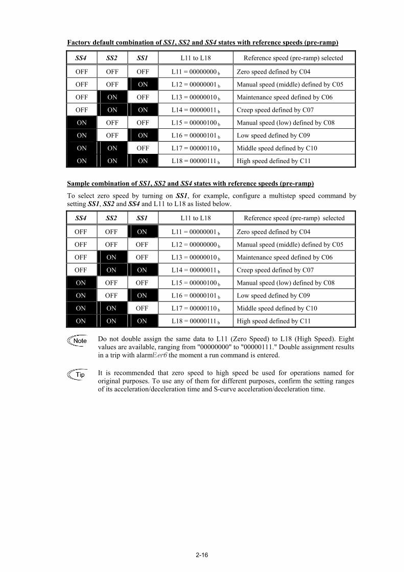
Factory default combination of SS1, SS2 and SS4 states with reference speeds (pre-ramp)
SS4 SS2 SS1 L11 to L18 Reference speed (pre-ramp) selected
OFF OFF OFF L11 = 00000000 b Zero speed defined by C04
OFF OFF ON L12 = 00000001 b Manual speed (middle) defined by C05
OFF ON OFF L13 = 00000010 b Maintenance speed defined by C06
OFF ON ON L14 = 00000011 b Creep speed defined by C07
ON OFF OFF L15 = 00000100 b Manual speed (low) defined by C08
ON OFF ON L16 = 00000101 b Low speed defined by C09
ON ON OFF L17 = 00000110 b Middle speed defined by C10
ON ON ON L18 = 00000111 b High speed defined by C11 Sample combination of SS1, SS2 and SS4 states with reference speeds (pre-ramp)
To select zero speed by turning on SS1, for example, configure a multistep speed command by setting SS1, SS2 and SS4 and L11 to L18 as listed below.
SS4 SS2 SS1 L11 to L18 Reference speed (pre-ramp) selected
OFF OFF ON L11 = 00000001 b Zero speed defined by C04
OFF OFF OFF L12 = 00000000 b Manual speed (middle) defined by C05
OFF ON OFF L13 = 00000010 b Maintenance speed defined by C06
OFF ON ON L14 = 00000011 b Creep speed defined by C07
ON OFF OFF L15 = 00000100 b Manual speed (low) defined by C08
ON OFF ON L16 = 00000101 b Low speed defined by C09
ON ON OFF L17 = 00000110 b Middle speed defined by C10
ON ON ON L18 = 00000111 b High speed defined by C11
Do not double assign the same data to L11 (Zero Speed) to L18 (High Speed). Eight values are available, ranging from "00000000" to "00000111." Double assignment results in a trip with alarmEer6 the moment a run command is entered.
It is recommended that zero speed to high speed be used for operations named for original purposes. To use any of them for different purposes, confirm the setting ranges of its acceleration/deceleration time and S-curve acceleration/deceleration time.

2-17
Acceleration/deceleration times to be applied when the reference speed (pre-ramp) is changed after the reference speed (final) reaches the speed (pre-ramp)
The table below lists the acceleration/deceleration times to be applied when the reference speed (pre-ramp) is changed after the reference speed (final) reaches the previously commanded reference speed (pre-ramp). Those times are specified by function codes F07, F08, and E10 to E17. In the table below, "Stop" refers to a run command being off. F07/F08 indicates that F07 and F08 apply during acceleration and deceleration, respectively.
After change
Before change
Stop Zero speed
Manual speed
(middle)Maintenance
speed Creep speed
Manual speed (low)
Low speed
Middle speed
High speed
Stop -/F08 F07 F07 F07 F07 F07 F07 F07 F07
Zero speed E16 F07/F08 E10 F07 F07/F08 F07 F07 E10 E12
Manual speed (middle) E16 E11 F07/F08 F07/F08 E11 F07/F08 F07/F08 F07/F08 F07/F08
Maintenance speed E16 F08 F07/F08 F07/F08 F07/F08 F07/F08 F07/F08 F07/F08 F07/F08
Creep speed E15 E14 F07/F08 F07/F08 F07/F08 F07/F08 F07/F08 F07/F08 F07/F08
Manual speed (low) E16 F08 F07/F08 F07/F08 F08 F07/F08 F07/F08 F07/F08 F07/F08
Low speed E16 F08 F07/F08 F07/F08 F08 F07/F08 F07/F08 F07/F08 F07/F08
Middle speed E16 E11 F07/F08 F07/F08 E11 F07/F08 E11 F07/F08 F07/F08
High speed E16 E13 F07/F08 F07/F08 E13 F07/F08 E13 F07/F08 F07/F08
S-curve starting/ending zones to be applied when the reference speed (pre-ramp) is changed after the reference speed (final) reaches the speed (pre-ramp)
The table below lists the S-curve starting/ending zones to be applied when the reference speed (pre-ramp) is changed after the reference speed (final) reaches the speed (pre-ramp). They are specified by function codes L19 to L28. In the table below, for example, L19/L22 indicates that L19 and L22 apply at the starting and ending zones, respectively.
When two different creep speeds are applied, set the low speed for the higher creep one.
After change
Before change
Stop Zero speed
Manual speed
(middle)Maintenance
speed Creep speed
Manual speed (low)
Low speed
Middle speed
High speed
Stop -/- -/- -/- -/- -/- -/- -/- -/- -/-
Zero speed -/- -/- L19/L22 -/- -/- L19/L20 L19/L20 L19/L22 L19/L24
Manual speed (middle) -/- L23/L28 -/- -/- L23/L26 -/- -/- -/- -/-
Maintenance speed -/- -/- -/- -/- -/- -/- -/- -/- -/-
Creep speed L27 L28 -/- -/- -/- -/- -/- -/- -/-
Manual speed (low) -/- L21/L28 -/- -/- L21/L26 -/- -/- -/- -/-
Low speed -/- L21/L28 -/- -/- L21/L26 -/- -/- -/- -/-
Middle speed -/- L23/L28 -/- -/- L23/L26 -/- L23/L26 -/- -/-
High speed -/- L25/L28 -/- -/- L25/L26 -/- L25/L26 -/- -/-
2-18
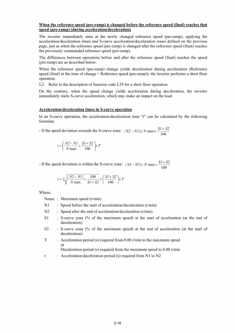
When the reference speed (pre-ramp) is changed before the reference speed (final) reaches that speed (pre-ramp) (during acceleration/deceleration)
The inverter immediately aims at the newly changed reference speed (pre-ramp), applying the acceleration/deceleration times and S-curve acceleration/deceleration zones defined on the previous page, just as when the reference speed (pre-ramp) is changed after the reference speed (final) reaches the previously commanded reference speed (pre-ramp). The differences between operations before and after the reference speed (final) reaches the speed (pre-ramp) are as described below. When the reference speed (pre-ramp) change yields deceleration during acceleration (Reference speed (final) at the time of change > Reference speed (pre-ramp)), the inverter performs a short floor operation.
Refer to the description of function code L29 for a short floor operation. On the contrary, when the speed change yields acceleration during deceleration, the inverter immediately starts S-curve acceleration, which may make an impact on the load. Acceleration/deceleration times in S-curve operation
In an S-curve operation, the acceleration/deceleration time "t" can be calculated by the following formulae.
- If the speed deviation exceeds the S-curve zone: 100
max || S2S1NN1N2 +×≥−
TS2S1N
N1N2t ×
++
−=
100max
- If the speed deviation is within the S-curve zone: 100
max || S2S1NN2N1 +×<−
TS2S1S2S1N
N1N2t ×
+
×+
×−
=100
100max
||2
Where, Nmax : Maximum speed (r/min) N1 : Speed before the start of acceleration/deceleration (r/min) N2 : Speed after the end of acceleration/deceleration (r/min) S1 : S-curve zone (% of the maximum speed) at the start of acceleration (at the end of
deceleration) S2 : S-curve zone (% of the maximum speed) at the end of acceleration (at the start of
deceleration) T : Acceleration period (s) required from 0.00 r/min to the maximum speed
or Deceleration period (s) required from the maximum speed to 0.00 r/min
t : Acceleration/deceleration period (s) required from N1 to N2

2-19
Operation samples
The following diagrams show operation samples given when the inverter runs by factory defaults of function codes L11 to L18. Changing those code data makes the relationship between terminal commands SS1, SS2 and SS4 and the reference speed (pre-ramp) selected different from the following diagrams.
Low speed
Low speedL20: S-curve setting 2
L19: S-curve setting 1
L21: S-curve setting 3
F07: Acceleration/deceleration time 1
F08: Acceleration/deceleration time 2
E14: Acceleration/deceleration time 7Time
Creep speed
Speed
Zero speed
L26: S-curve setting 8L28: S-curve setting 10
L28: S-curve setting 10
ONFWD
SS1
SS2
ON
ON
SS4 ON
Zero speedcommand
Low speedcommand
Creep speedcommand
Zero speedcommand
Middle speed L22: S-curve setting 4
Speed
Middle speed
Zero speed
Creep speed
ONFWD
SS1
SS2
ON
ON
SS4 ON
Zero speedcommand
Middle speedcommand
Creep speedcommand
Zero speedcommand
L19: S-curve setting 1
L23: S-curve setting 5
E10: Acceleration/deceleration time 3
E11: Acceleration/deceleration time 4
E14: Acceleration/deceleration time 7 Time
L26: S-curve setting 8
L28: S-curve setting 10
L28: S-curve setting 10

2-20
High speed
Speed
High speed
ONFWD
SS1
SS2
ON
ON
SS4 ON
Zero speedcommand
High speedcommand
Creep speedcommand
Zero speedcommand
Creep speed
Zero speedL19: S-curve setting 1
E14: Acceleration/deceleration time 7Time
L26: S-curve setting 8 L28: S-curvesetting 10
L28: S-curve setting 10
E12: Acceleration/deceleration time 5
E13: Acceleration/deceleration time 6
L25: S-curve setting 7L24: S-curve setting 6
Manual speed (Low)
Time
Speed
ONFWD
SS1
SS2
ON
SS4 ON
ON
Zero speedcommand
Manual speed (Low)command
Creep speedcommand
Zero speedcommand
Creep speed
Zero speed
Manualspeed (Low)
L19: S-curve setting 1
E14: Acceleration/deceleration time 7
L26: S-curve setting 8
F07: Acceleration/deceleration time 1
L20: S-curve setting 2L21: S-curve setting 3
L28: S-curvesetting 10
L28: S-curve setting 10
F08: Acceleration/deceleration time 2

2-21
Speed
Time
Manual speed (Middle)
ONFWD
SS1
SS2
ON
SS4
ON
Zero speedcommand
Manual speed(Middle) command
Creep speedcommand
Zero speedcommand
Creep speed
Zero speed
Manualspeed (Middle)
L19: S-curve setting 1
E14: Acceleration/deceleration time 7
L26: S-curve setting 8 L28: S-curvesetting 10
L28: S-curve setting 10
E11: Acceleration/deceleration time 4E10: Acceleration/deceleration time 3
L22: S-curve setting 4 L23: S-curve setting 5
High speed
Speed
TimeZero speed
Creep speed
ONFWD
SS1
SS2
ON
ON
SS4 ON
Stop speed
Output shutdown
H67: Stop speed(Holding time)
Creep speed to stop
Zero speedcommand
High speedcommand
Creep speedcommand
Stopcommand
E15: Acceleration/deceleration time 8
L19: S-curve setting 1 L26: S-curve setting 8
E12: Acceleration/deceleration time 5
E13: Acceleration/deceleration time 6
L25: S-curve setting 7L24: S-curve setting 6
L27: S-curvesetting 9
L27: S-curve setting 9
2-22
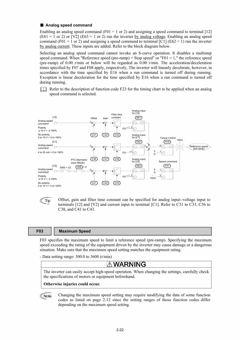
Analog speed command Enabling an analog speed command (F01 = 1 or 2) and assigning a speed command to terminal [12] (E61 = 1 or 2) or [V2] (E63 = 1 or 2) run the inverter by analog voltage. Enabling an analog speed command (F01 = 1 or 2) and assigning a speed command to terminal [C1] (E62 = 1) run the inverter by analog current. These inputs are added. Refer to the block diagram below. Selecting an analog speed command cannot invoke an S-curve operation. It disables a multistep speed command. When "Reference speed (pre-ramp) < Stop speed" or "F01 = 1," the reference speed (pre-ramp) of 0.00 r/min or below will be regarded as 0.00 r/min. The acceleration/deceleration times specified by F07 and F08 apply, respectively. The inverter will linearly decelerate, however, in accordance with the time specified by E16 when a run command is turned off during running. Exception is linear deceleration for the time specified by E16 when a run command is turned off during running.
Refer to the description of function code F23 for the timing chart to be applied when an analog speed command is selected.
0%
H180
1
F01
1
2
0%
-100%
E63
1, 2
E62
1
×
C42C41
+
-
C43
×
C37C36
+
-
C38
×
C32C31
+
-
C33
100%
0%
0%
0%
+
+
+
E61
1, 2
H26 = 0SW5 = V2
[12]Analog speedcommandPolarity±10 V = ±100%No polarity0 to 10 V = 0 to 100%
[C1]
4 to 20 mA = 0 to 100%
Analog speedcommand
Offset GainFilter timeconstant
Reference speed(pre-ramp)
[V2]Analog speedcommandPolarity±10 V = ±100%No polarity0 to 10 V = 0 to 100%
PTC thermistorinput (Mode) Speed command
Torque control
Analog inputfor [12]
Analog inputfor [C1]
Analog inputfor [V2]
≠
≠
≠
Offset, gain and filter time constant can be specified for analog input--voltage input to terminals [12] and [V2] and current input to terminal [C1]. Refer to C31 to C33, C36 to C38, and C41 to C43.
F03 Maximum Speed F03 specifies the maximum speed to limit a reference speed (pre-ramp). Specifying the maximum speed exceeding the rating of the equipment driven by the inverter may cause damage or a dangerous situation. Make sure that the maximum speed setting matches the equipment rating. - Data setting range: 300.0 to 3600 (r/min)
The inverter can easily accept high-speed operation. When changing the settings, carefully check the specifications of motors or equipment beforehand.
Otherwise injuries could occur.
Changing the maximum speed setting may require modifying the data of some function codes as listed on page 2-12 since the setting ranges of those function codes differ depending on the maximum speed setting.

2-23
F04 Rated Speed F05 Rated Voltage
F04 and F05 specify the rated speed and voltage of the motor that the inverter drives. Rated speed (F04) Set the rated speed printed on the nameplate labeled on the motor. - Data setting range: 300.0 to 3600.0 (r/min) Rated voltage (F05) Set the rated voltage printed on the nameplate labeled on the motor. Note that the inverter cannot output the voltage exceeding the inverter's input voltage. - Data setting range: 160 to 500 (V)
F07, F08 Acceleration/Deceleration Time 1, 2 E10 to E17 (Acceleration/Deceleration Time 3 to 10)
F07 and F08 specify the acceleration or deceleration time in linear acceleration/deceleration zones excluding S-curve zones. The acceleration/deceleration time is the length of time required for the speed to linearly increase from 0.00 r/min to the maximum speed (F03) or decrease from the maximum speed to 0.00 r/min, respectively. - Data setting range: 0.00 to 99.9 (s)
Actual length of timerequired for reachingthe maximum speed
Actual length of timerequired for reaching0.00 (r/min.)
Maximumspeed
Speed
Accelerationtime (F07)
Decelerationtime (F08)
Time
When the inverter runs by an analog speed command, the acceleration and deceleration times specified by F07 and F08 apply. To generate acceleration/deceleration patterns with the host controller, modify F07 and F08 data. Also in local mode, the acceleration and deceleration times specified by F07 and F08 apply.

2-24
F10 Electronic Thermal Overload Protection for Motor (Select motor
characteristics) F11 Electronic Thermal Overload Protection for Motor (Overload detection level) F12 Electronic Thermal Overload Protection for Motor (Thermal time constant)
F10 through F12 specify the thermal characteristics of the motor for its electronic thermal overload protection that is used to detect overload conditions of the motor inside the inverter.
Select motor characteristics (F10) F10 specifies the cooling mechanism of the motor--built-in cooling fan or externally powered forced-ventilation fan.
Data for F10 Function
1 For general-purpose motors with built-in self-cooling fan (The cooling effect will decrease in low speed operation.)
2 For inverter-driven motors or high-speed motors with forced-ventilation fan (The cooling effect will be kept constant regardless of the output speed.)
The figure below shows operation characteristics of the electronic thermal overload protection.
Cooling Characteristics of Motor Equipped with a Self-cooling Fan
Switching frequency for motor
characteristic factor
Characteristic factor(%) F10 data
Applicable motor rating
(kW)
Thermal time constant
(Factory default)f2 f3 α1 α2 α3
5.5 to 11 kW 6 Hz 90 95 100
15 kW 7 Hz 85 85 1001
18.5, 22 kW
5 Hz
5 Hz 92 100 100
2 -
5 min
- - 100 100 100 Overload detection level (F11) F11 specifies the level at which the electronic thermal overload protection becomes activated. - Data setting range: 0.00 (Disable) 1 to 200% of the rated current (allowable continuous drive current) of the
inverter.
In general, set F11 to the allowable continuous drive current of the motor when driven at the rated speed (i.e. 1.0 to 1.1 multiple of the rated current of the motor). To disable the electronic thermal overload protection, set F11 to "0.00."

2-25
Thermal time constant (F12) F12 specifies the thermal time constant of the motor. The time constant refers to the time required for the electronic thermal overload protection to detect a motor overload when the current of 150% of the overload detection level specified by F11 has flown continuously. - Data setting range: 0.5 to 75.0 (min)
(Example) When F12 is set at "5.0" (5 minutes) As shown below, the electronic thermal overload protection is activated to detect an alarm condition (Alarm 0l1 ) when the output current of 150% of the overload detection level (specified by F11) flows for 5 minutes. The actual activation time required for issuing a motor overload alarm tends to be shorter than the one specified by F12 since it takes into account the time period from when the output current exceeds the rated current (100%) until it reaches 150% of the overload detection level.
Example of Operating Characteristics
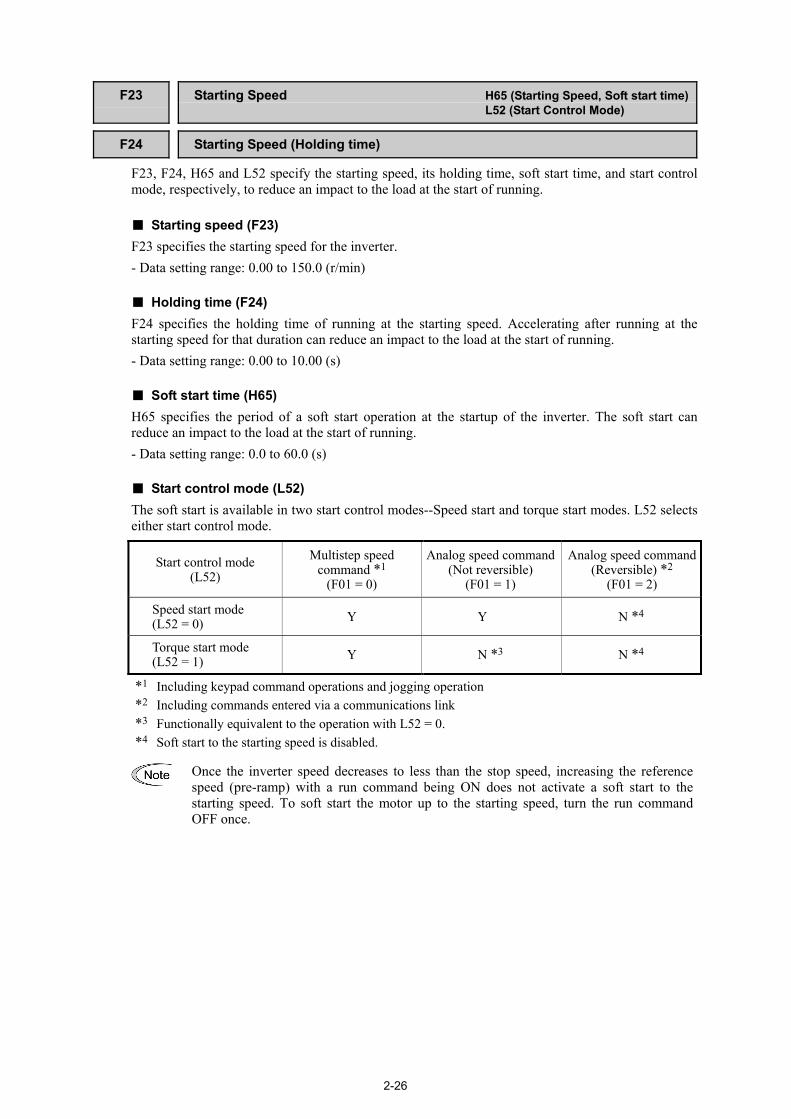
2-26
F23 Starting Speed H65 (Starting Speed, Soft start time)
L52 (Start Control Mode) F24 Starting Speed (Holding time)
F23, F24, H65 and L52 specify the starting speed, its holding time, soft start time, and start control mode, respectively, to reduce an impact to the load at the start of running.
Starting speed (F23) F23 specifies the starting speed for the inverter. - Data setting range: 0.00 to 150.0 (r/min)
Holding time (F24) F24 specifies the holding time of running at the starting speed. Accelerating after running at the starting speed for that duration can reduce an impact to the load at the start of running. - Data setting range: 0.00 to 10.00 (s)
Soft start time (H65) H65 specifies the period of a soft start operation at the startup of the inverter. The soft start can reduce an impact to the load at the start of running. - Data setting range: 0.0 to 60.0 (s)
Start control mode (L52) The soft start is available in two start control modes--Speed start and torque start modes. L52 selects either start control mode.
Start control mode (L52)
Multistep speed command *1
(F01 = 0)
Analog speed command(Not reversible)
(F01 = 1)
Analog speed command(Reversible) *2
(F01 = 2)
Speed start mode (L52 = 0) Y Y N *4
Torque start mode (L52 = 1) Y N *3 N *4
*1 Including keypad command operations and jogging operation *2 Including commands entered via a communications link *3 Functionally equivalent to the operation with L52 = 0. *4 Soft start to the starting speed is disabled.
Once the inverter speed decreases to less than the stop speed, increasing the reference speed (pre-ramp) with a run command being ON does not activate a soft start to the starting speed. To soft start the motor up to the starting speed, turn the run command OFF once.

2-27
Speed start mode
Setting L52 data to "0" enables the speed start mode.
(i) When a multistep speed command with S-curve acceleration/deceleration is enabled (F01 = 0) If the reference speed (pre-ramp) exceeds the starting speed, the inverter activates a soft start to the starting speed. After the holding time of running at the starting speed (specified by F24), the inverter accelerates up to the reference speed (pre-ramp).
Invertermain circuit
(output gate)
Runcommand
Startingspeed
Startingspeed
Referencespeed
(pre-ramp)
ON
ON
L85 H65 F24
Referencespeed(final)
If the stop speed is specified exceeding the starting speed, the inverter does not activate a soft start as long as the reference speed (pre-ramp) does not exceed the stop speed.
(ii) When an analog speed command (Not reversible) is enabled (F01 = 1) Turning a run command ON activates a soft start. When the speed reaches the starting one, the inverter stands by. When the reference speed (pre-ramp) exceeds the starting speed, the inverter immediately accelerates from the current speed up to the reference speed (pre-ramp).
ON
ON
L85 H65F24
0
0
Invertermain circuit
(output gate)
Runcommand
Startingspeed
Startingspeed
Referencespeed
(pre-ramp)
Referencespeed(final)
If the stop speed is specified exceeding the starting speed, the inverter does not start acceleration to the reference speed (pre-ramp) as long as the reference speed (pre-ramp) does not exceed the stop speed.

2-28
(iii) When an analog speed command (Reversible) is enabled (F01 = 2) The inverter does not activate a soft start to the starting speed. When the reference speed (pre-ramp) exceeds the starting speed, the inverter starts acceleration to the reference speed (pre-ramp).
ON
ON
L85 F24
0
0
Invertermain circuit
(output gate)
Runcommand
Startingspeed
Startingspeed
Referencespeed
(pre-ramp)
Referencespeed (final)
If the stop speed is specified exceeding the starting speed, the inverter does not start acceleration to the reference speed (pre-ramp) as long as the reference speed (pre-ramp) does not exceed the stop speed.
Torque start mode
Setting L52 data to "1" enables the torque start mode. In this mode, the inverter increases the output voltage to generate torque along the slope specified by the time (F24) in the rotation direction specified by a run command. When the detected speed exceeds the starting speed (F23), the inverter starts the speed control to accelerate smoothly. When F23 = 0.00, this mode is disabled.
In the torque start mode, a PG error may occur or the DSAG command on the general-purpose output terminal may go OFF depending upon the starting speed setting.
Time
Reference speed (final)
0
ONFWD
ON
Torque commandτ*
Detected speed
0F23: Starting speed
Time
Time
Time
Acceleration command
0
SS1
(%/s)
H65100τ*
=∆∆
t

2-29
F25 Stop Speed H66 (Stop Speed, Detection method)
H67 (Stop Speed, Holding time) F25, H66, and H67 specify the stop speed, its detection method, and its holding time, respectively, to reduce an impact to the load at the end of running. Stop speed (F25) F25 specifies the stop speed for the inverter. If the reference speed (pre-ramp) is specified below the stop speed, it will be regarded as 0.00 (r/min). - Data setting range: 0.00 to 150.0 (r/min) Detection method (H66) H66 selects whether to use the detected speed or reference speed (final) for detecting the stop speed.
Data for H66 Function
0 Use detected speed
1 Use reference speed (final) Holding time (H67) H67 specifies the holding time of continuous running after the detection of the stop speed even with a run command being OFF. If H67 data is set to 0.00 (s), turning the run command OFF and detecting the stop speed shut down the inverter output. - Data setting range: 0.00 to 10.00 (s)
Stop speedholding time (H67)
Stop speed
Detected speedor
reference speed (final)
ON
ONRun command
Inverter main circuit(output gate)

2-30
F26 Motor Sound (Carrier frequency) H98 (Protection/Maintenance Function)
F26 controls the carrier frequency so as to reduce an audible noise generated by the motor or inverter itself, and to decrease a leakage current from the main output (secondary) wirings.
Carrier frequency 5 kHz ↔ 15 kHz
Motor sound noise emission High ↔ Low
Motor temperature (due to harmonics components) High ↔ Low
Ripples in output current waveform Large ↔ Small
Leakage current Low ↔ High
Electromagnetic noise emission Low ↔ High
Inverter loss Low ↔ High
Specifying a too low carrier frequency will cause the output current waveform to have a large amount of ripples (many harmonics components). As a result, the motor loss increases, causing the motor temperature to rise. Furthermore, the large amount of ripples tends to cause a current limiting alarm. When a high carrier frequency is specified, the temperature of the inverter may rise due to an ambient temperature rise or an increase of the load. If it happens, the inverter automatically decreases the carrier frequency to prevent the inverter overheat alarm 0h3 or inverter overload alarm 0lu . With consideration for motor noise, the automatic reduction of carrier frequency can be disabled (see function code H98).
F42 Control Mode F42 selects the control mode.
Data for F42 Function
0 Vector control with PG for asynchronous motor
1 Vector control with PG for synchronous motor
F44 Current Limiter (Level) F44 specifies the activation level of the current limiter. When the output current of the inverter exceeds the level specified by F44, the current limiter works to manage the output current and reduce the motor torque. When the output current drops below the level specified by F44, the inverter returns to the normal operation. - Data setting range: 100 to 200 (%) (Percentage to the rated current of the inverter) 999 (The maximum current of each inverter automatically applies.)
Since the current limit operation with F44 is performed by software, it may cause a delay in control.

2-31
2.2.2 E codes (Extension terminal functions)
E01 to E08 Command Assignment to [X1] to [X8] E98 and E99 (Command Assignment to [FWD] and [REV])
E01 to E08, E98 and E99 allow you to assign commands to terminals [X1] to [X8], [FWD], and [REV] which are general-purpose, programmable input terminals. These function codes may also switch the logic system between normal and negative to define how the inverter logic interprets either ON or OFF status of each terminal. The default setting is normal logic system "Active ON." Following table show the commands that can be assigned with the general-purpose programmable input terminals [X1] to [X8], [FWD], and [REV]. Explanations for the commands that follow are given in normal logic system "Active ON."
To the general-purpose programmable input terminals, you can assign commands to the switching means for the run command and its operation, the reference speed (pre-ramp) and the motor drive power.
Be aware of that switching of any of such signals may cause a sudden start (running) or an abrupt change in speed. An accident or physical injury may result.
Function code data
Active ON Active OFF Terminal commands assigned Symbol
0 1000 Select multistep speed 1 SS1
1 1001 Select multistep speed 2 SS2
2 1002 Select multistep speed 4 SS4
7 1007 Enable coast-to-stop BX
8 1008 Reset alarm RST
1009 9 Enable external alarm trip THR
10 1010 Enable jogging operation JOG
24 1024 Enable communications link via RS485 or CAN LE
25 1025 Universal DI U-DI
27 1027 Enable PG vector control PG/Hz
60 1060 Select torque bias 1 TB1
61 1061 Select torque bias 2 TB2
62 1062 Hold torque bias H-TB
63 1063 Enable battery operation BATRY
64 1064 Start creepless operation CRPLS
65 1065 Check brake control BRKE
1066 66 Force to decelerate DRS
67 1067 Start unbalance load compensation UNBL
98 - Run forward (Exclusively assigned to [FWD] and [REV] terminals by E98 and E99) FWD
99 - Run reverse (Exclusively assigned to [FWD] and [REV] terminals by E98 and E99) REV

2-32
Any negative logic (Active OFF) command cannot be assigned to the functions marked with "-" in the "Active OFF" column. The "Enable external alarm trip" and "Force to decelerate" are fail-safe terminal commands. For example, when data = "9" in "Enable external alarm trip," Active OFF (alarm is triggered when OFF); when data = 1009, "Active ON" (alarm is triggered when ON).
Terminal function assignment and data setting
Select multistep speed -- SS1, SS2, and SS4 (Function code data = 0, 1, and 2)
The combination of ON/OFF states of digital input signals SS1, SS2, and SS4 selects one of eight different speed commands.
For details, refer to the description of function code F01 (Speed Command).
Coast to a stop -- BX (Function code data = 7)
Turning this terminal command ON immediately stops the inverter output so that the motor coasts to a stop without issuing any alarm. Turning it OFF restarts the inverter.
Reset alarm -- RST
(Function code data = 8) Turning this terminal command ON clears the ALM state--alarm output (for any alarm). Turning it OFF erases the alarm display and clears the alarm hold state. When you turn the RST command ON, keep it ON for 10 ms or more. This command should be kept OFF for the normal inverter operation.
Enable external alarm trip -- THR
(Function code data = 9) Turning this terminal command OFF immediately shuts down the inverter output (so that the motor coasts to a stop), displays the alarm 0h2, and outputs the alarm relay (for any alarm) ALM. The THR is self-held, and is reset when an alarm reset takes place.
Use a trip command from external equipment when you have to immediately shut down the inverter output in the event of an abnormal situation in a peripheral equipment.
Enable jogging operation -- JOG
(Function code data = 10)
Turning this terminal command ON enables jogging operation.
For details, refer to the description of function code C20 (Jogging Speed).
Enable communications link via RS485 or CAN -- LE (Function code data = 24)
Turning this terminal command ON runs the motor according to the frequency commands or run commands received via the communications link selected with function code H30 (RS485 or CAN). No LE assignment is functionally equivalent to the LE being ON.
For details, refer to the description of function code H30 (Communications Link Operation).
2-33
Universal DI -- U-DI (Function code data = 25)
Using U-DI enables the inverter to monitor digital signals sent from the peripheral equipment via an RS485 or CAN communications link by feeding those signals to the digital input terminals. Signals assigned to the universal DI are simply monitored and do not operate the inverter.
For an access to universal DI via the RS485 or CAN communications link, refer to their respective Instruction Manuals.
Enable PG vector control -- PG/Hz
(Function code data = 27) Turning this terminal command OFF cancels the PG vector control and switches to the V/f control. The ON/OFF switching when the inverter is in operation will not be validated; it will be after the inverter stops. Whenever this terminal command is not assigned, the PG vector control is effective by default. Enabling the torque control (H18 = 1) disables this terminal command.
Torque Bias 1 and 2 -- TB1 and TB2
(Function code data = 60 and 61) Selecting TB1 or TB2 allows you to set digital torque bias.
For details, refer to the description of function code L54 (Torque Bias, Mode).
Hold torque bias -- H-TB
(Function code data = 62) Turning this terminal command ON holds torque bias setting. Turning it OFF release the hold status.
For details, refer to the description of function code L55 (Torque Bias, Startup time).
Enable battery operation -- BATRY
(Function code data = 63) Turning this terminal command ON selects operation by batteries.
For details, refer to the description of function code C03 (Battery Operation Speed).
Start creepless operation -- CRPLS
(Function code data = 64) Turning this terminal command ON starts creepless operation.
For details, refer to the description of function code L34 (Elevator Parameter, Moving distance in creepless operation).
Check brake control -- BRKE
(Function code data = 65) This terminal command is used to check whether or not the actual brake is working normally, using the BRKS output from the inverter. Configure an external circuit that turns this command ON or OFF when the brake is released or activated, respectively.
For details, refer to the descriptions of function codes L80 to L84 (Brake Control).
Force to decelerate -- DRS
(Function code data = 66) In normal inverter operation, this terminal command should be ON. If this terminal command is OFF, the motor will be forced to decelerate with deceleration time specified by function code H56.
For details, refer to the description of function code H56 (Deceleration Time for Forced to Decelerate).

2-34
Start unbalance load compensation -- UNBL (Function code data = 67)
Turning this terminal command ON starts unbalance load compensation. Synchronize brake control signal from the user controller. When this terminal command is OFF, unbalance load compensation will be started after run command is ON.
For details, refer to the descriptions of function codes L65 to L69 (Unbalanced Load Compensation).
Run forward -- FWD
(Function code data = 98) Turning this terminal command ON runs the motor in the forward direction; turning it OFF decelerates it to stop.
This terminal command can be assigned only by E98 or E99.
Run reverse -- REV (Function code data = 99)
Turning this terminal command ON runs the motor in the reverse direction; turning it OFF decelerates it to stop.
This terminal command can be assigned only by E98 or E99.
E10 to E17 Acceleration/Deceleration Time 3 to 10 F07 and F08 (Acceleration/Deceleration Time 1 and 2)
E10 to E17 specify the acceleration or deceleration time in linear acceleration/deceleration zones excluding S-curve zones.
For details, refer to the descriptions of function codes F07 to F08 (Acceleration/Deceleration Time 1, 2).
E18 Run Command/Multistep Speed Command Agreement Timer (Mode)
E19 Run Command/Multistep Speed Command Agreement Timer (Time)
E18 and E19 set the run command/multistep speed command agreement timer for eliminating chattering.
Mode (E18) E18 specifies applicable commands for the agreement timer.
Applicable commands Data for E18
FWD, REV SS1, SS2, SS4
0 -- --
1 √ --
2 -- √
3 √ √
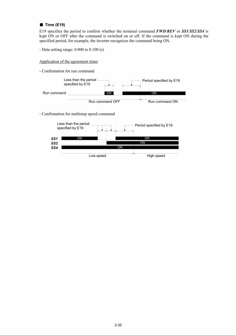
2-35
Time (E19) E19 specifies the period to confirm whether the terminal command FWD/REV or SS1/SS2/SS4 is kept ON or OFF after the command is switched on or off. If the command is kept ON during the specified period, for example, the inverter recognizes the command being ON. - Data setting range: 0.000 to 0.100 (s)
Application of the agreement timer
- Confirmation for run command
Run command ON ON
Period specified by E19
Run command OFF Run command ON
Less than the periodspecified by E19
- Confirmation for multistep speed command
Less than the periodspecified by E19
SS1SS2
ON ON
Period specified by E19
Low speed High speed
SS4 ONON

2-36
E20 to E23 E24, E27
Signal Assignment to [Y1] to [Y4] (Transistor signal) Signal Assignment to [Y5A/C] and [30A/B/C] (Relay contact signal)
E20 to E24 and E27 assign output signals (listed on the next page) to general-purpose, programmable output terminals [Y1] through [Y4], [Y5A/C], and [30A/B/C]. These function codes can also switch the logic system between normal and negative to define the property of those output terminals so that the inverter logic can interpret either the ON or OFF status of each terminal as active. The factory default settings are "Active ON." Terminals [Y1] through [Y4] are transistor outputs and terminals, [Y5A/C] and [30A/B/C] are relay contact outputs. In normal logic, if an alarm occurs, the relay will be energized so that [30A] and [30C] will be closed, and [30B] and [30C] opened. In negative logic, the relay will be deenergized so that [30A] and [30C] will be opened, and [30B] and [30C] closed. This may be useful for the implementation of failsafe power systems.
• When a negative logic is employed, all output signals are active (e.g. an alarm would be
recognized) while the inverter is powered OFF. To avoid causing system malfunctions bythis, interlock these signals to keep them ON using an external power source. Furthermore, the validity of these output signals is not guaranteed for approximately 3seconds after power-on, so introduce such a mechanism that masks them during thetransient period.
• Terminals [Y5A/C] and [30A/B/C]) use mechanical contacts that cannot stand frequent ON/OFF switching. Where a frequent ON/OFF switching is anticipated, use transistoroutputs [Y1] through [Y4]. The service life of a relay is approximately 200,000 times if itis switched on and off at one-second intervals.
The table on the following page lists functions that can be assigned to terminals [Y1] through [Y4], [Y5A/C], and [30A/B/C]. To make the explanation simpler, the examples shown below are all written for the normal logic (Active ON).

2-37
Function code data
Active ON Active OFF Functions assigned Symbol
0 1000 Inverter running RUN
1 1001 Speed arrival FAR
2 1002 Speed detected FDT
3 1003 Undervoltage detected LU
10 1010 Inverter ready to run RDY
12 1012 MC control SW52-2
25 1025 Cooling fan in operation FAN
26 1026 Auto-resetting TRY
27 1027 Universal DO U-DO
28 1028 Overheat early warning OH
30 1030 Service life alarm LIFE
35 1035 Inverter output on RUN2
37 1037 Current detected ID
38 1038 Current detected 2 ID2
55 1055 Run command activated AX2
56 1056 Motor overheat detected (PTC) THM
57 1057 Brake control BRKS
70 1070 Speed existence DNZS
71 1071 Speed agreement DSAG
72 1072 Speed arrival 3 FAR3
73 1073 During acceleration DACC
74 1074 During deceleration DDEC
75 1075 During zero speed DZR
76 1076 PG abnormal PG-ABN
78 1078 Door control DOPEN
99 1099 Alarm output (for any alarm) ALM
101 1101 EN detection circuit fault DECF
102 1102 EN terminal off ENOFF
104 1104 Low voltage detected LVD

2-38
Inverter running -- RUN (Function code data = 0)
This output signal is used to tell the external equipment whether the inverter is running. Turning the inverter main circuit (output gate) ON or OFF switches the RUN signal ON or OFF, respectively. This signal is also OFF when the motor is being tuned. If this signal is assigned in negative logic (Active OFF), it can be used as a signal indicating "inverter being stopped."
Speed arrival -- FAR
(Function code data = 1) This output signal comes ON when the difference between the detected speed and reference speed (pre-ramp) comes within the allowable error zone (specified by E30). When the run command for the inverter is OFF, this output signal also comes OFF.
For details, refer to the description of function code E30 (Speed Arrival).
Speed detected -- FDT (Function code data = 2)
This output signal comes ON when the detected speed exceeds the speed detection level specified by E31, and it goes OFF when the detected speed drops below the "Detection level (E31) - Hysteresis band width (E32)." This output signal is not affected by a run command.
For details, refer to the description of function codes E31 and E32 (Speed Detection).
Undervoltage detected -- LU (Function code data = 3)
This output signal comes ON when the DC link bus voltage of the inverter drops below the specified undervoltage level, and it goes OFF when the voltage exceeds the level. This signal is ON also when the undervoltage protective function is activated so that the motor is in an abnormal stop state (e.g., tripped).
Inverter ready to run -- RDY
(Function code data = 10) This output signal comes ON when the inverter becomes ready to run by satisfying all of the following conditions. - Terminal [EN] ON - BX OFF - No alarm detected - DC link bus voltage higher than the specified undervoltage level - Initialization of options completed Note that the entry of a BATRY command always turns the RDY signal OFF.
MC control -- SW52-2
(Function code data = 12) This output signal is used for MC control.
For details, refer to the descriptions of function codes L85 and L86 (MC Control).
Cooling fan in operation -- FAN (Function code data = 25)
This output signal is ON when the cooling fan is in operation, and OFF when it is stopped. This signal can be used to make the cooling system of peripheral equipment interlocked for an ON/OFF control.

2-39
Auto-resetting -- TRY (Function code data = 26)
This output signal comes ON when auto-resetting is in progress. The auto-resetting is specified by H04 and H05. Refer to the descriptions of function codes
H04 and H05 for details about the number of resetting times and reset interval. Universal DO -- U-DO
(Function code data = 27) Assigning this output signal to an inverter's output terminal and connecting the terminal to a digital input terminal of peripheral equipment via the communications link RS485 or CAN, allows the inverter to send commands to the peripheral equipment. The universal DO can be used as an output signal independent of the inverter operation.
For the procedure for access to Universal DO via the communications link RS485 or CAN, refer to the respective instruction manual.
Overheat early warning -- OH
(Function code data = 28) This output signal issues an overheat early warning before an overheat trip actually occurs due to the temperature on the inverter's heat sink (0h1 ) or inside the inverter (0h3 ) or due to an inverter overload (0lu ). If this signal is turned ON, take any appropriate measures such as stop of the inverter operation and enhancement of external cooling.
For details, refer to the description of L93 (Overheat Early Warning Level).
Service life alarm -- LIFE
(Function code data = 30) This output signal comes ON when it is judged that the service life of any capacitors (reservoir capacitor in the DC link bus and electrolytic capacitors on the printed circuit boards) and cooling fan has expired. This signal should be used as a guide for replacement of the capacitors and cooling fan. If this signal comes ON, use the specified maintenance procedure to check the service life of these parts and determine whether the parts should be replaced or not.
For details, refer to the FRENIC-Lift Instruction Manual (INR-SI47-1038-E), Section 7.3, Table 7.3 "Criteria for Issuing a Lifetime Alarm."
Inverter output on -- RUN2
(Function code data = 35) This output signal comes ON when the inverter turns on its main circuit (output gate). It also comes ON when the motor is being tuned.
Current detected and Current detected 2 -- ID and ID2
(Function code data = 37 and 38) The ID or ID2 signal comes ON when the output current of the inverter exceeds the level specified by E34 or E37 (Current Detection, Level) for the time longer than the one specified by E35 (Current Detection, Time), provided that "37" or "38" is assigned to any general-purpose input terminal, respectively. The minimum ON-duration is 100 ms.
It goes OFF when the output current drops below 90% of the rated operation level.
For details, refer to the descriptions of function codes E34, E35 and E37.

2-40
Run command activated -- AX2 (Function code data = 55)
This status signal AX2 comes ON when the main circuit (output gate) is ON, or inverter receives run command with no alarm while LU is OFF. It goes OFF by stopping output when the inverter receives a stop command. It goes ON when the inverter receives an "Enable coast-to-stop" command BX, it goes OFF when the inverter protective function is activated.
Motor overheat detected (PTC) -- THM
(Function code data = 56) This output signal indicates that a temperature alarm condition has been detected by a PTC (Positive Temperature Coefficient) thermistor on the motor. With this output signal assigned, setting function code H26 (PTC Thermistor) to "2" enables the inverter to continue running instead of stopping with the alarm 0h4 even if a temperature alarm condition has been detected.
For details of the PTC thermistor, refer to the descriptions of function codes H26 and H27 (PTC Thermistor, Mode and Level).
Brake control -- BRKS
(Function code data = 57) This signal outputs a brake control command.
For details, refer to the descriptions of function codes L80 to L84 (Brake Control).
Speed existence -- DNZS
(Function code data = 70) This output signal comes ON when the detected speed is equal to or higher than the stop speed. It is not affected by any run command to the inverter.
Speed agreement -- DSAG
(Function code data = 71) This output signal comes ON when the difference between reference speed (final) and detected speed is within the range specified by H74 and it goes OFF when the difference is out of the allowable band for the time longer than the one specified by H75. It is not affected by any run command to the inverter.
For details, refer to the description of function codes H74 and H75 (Speed Agreement).
Speed arrival 3 -- FAR3
(Function code data = 72) This output signal comes ON when the difference between the detected speed and reference speed (pre-ramp) comes within the allowable error zone (specified by E30). It is not affected by any run command to the inverter.
For details, refer to the description of function code E30 (Speed Arrival).
During acceleration and During deceleration -- DACC and DDEC
(Function code data = 73 and 74) The output signal DACC or DDEC come ON depending on whether the motor is accelerating or decelerating by comparing the reference speed (pre-ramp) with the detected speed. These output signals are not affected by any run command to the inverter.
For details, refer to the description of function code E30 (Speed Arrival).

2-41
During zero speed -- DZR (Function code data = 75)
This output signal comes ON when the main circuit (output gate) of the inverter is ON and the detected speed is lower than the stop speed specified by function code F25.
PG abnormal -- PG-ABN
(Function code data = 76) This output signal comes ON when any PG error is detected.
For details, refer to the description of function codes L90 to L92 (PG Error Detection).
Door control -- DOPEN
(Function code data = 78) This output signal controls the elevator door.
For details, refer to the description of function codes L87 to L89 (Door Control).
Alarm output (for any alarm) -- ALM
(Function code data = 99) This output signal comes ON when any alarms occur.
EN detection circuit fault -- DECF
(Function code data = 101) This output signal comes ON when the [EN] status detection circuit is defective. It can be outputted separately from the relay alarm output.
EN terminal off -- ENOFF
(Function code data = 102) This is a status output signal that comes ON when the [EN] terminal is not available. It goes OFF when the output signal DECF is ON.
Low voltage detected -- LVD
(Function code data = 104) This output signal comes ON when a low voltage is detected.
2-42
E30 Speed Arrival (Hysteresis) H75 (Speed Agreement, Delay time)
E30 specifies the detection range of the speed arrival signal. - Data setting range: 0.00 to 3600 (r/min)
Output signals "Speed arrival FAR", "Speed arrival 3 FAR3", "During acceleration DACC" and "During deceleration DDEC"
The output signal FAR can be assigned to a general-purpose, programmable output terminal by setting "1" (E20 to E24 and E27). The FAR comes ON when the detected speed against the reference speed (pre-ramp) is within the specified range. However, if the run command is OFF or the reference speed (pre-ramp) is less than 0.00 (r/min) (less than the stop speed), it will not come ON. The output signal FAR3 can be also assigned by setting "72." The FAR3 comes ON when the detected speed against the reference speed (pre-ramp) is within the specified range. This output signal is not affected by any run command. The output signals DACC and DDEC can be also assigned by setting "73" and "74," respectively. The DACC or DDEC comes ON depending on whether the motor is accelerating or decelerating by comparing the reference speed (pre-ramp) with the detected speed. These output signals during accelerating and decelerating are turned OFF according to the level of the speed arrival hysteresis specified by E30. When the inverter is under torque control, none of these output signals FAR, FAR3, DACC and DDEC comes ON.
When the output signals FAR, DACC and DDEC are assigned, the ON-to-OFF delay time can be specified by function code H75 in order to prevent chattering. H75 can be used for the output signal DSAG.
Following is a timing chart for these output signals.

2-43
E31 Speed Detection (FDT) (Detection level) E32 Speed Detection (FDT) (Hysteresis)
E31 and E32 specify the speed detection level and hysteresis band width for the output signal FDT assigned to a general-purpose programmable output terminal by any of E20 to E24 and E27.
Speed detection level (E31) The output signal FDT is turned ON when the detected speed has exceeded the speed detection level specified by E31. - Data setting range: 0.00 to 3600 (r/min)
Speed detection hysteresis (E32) The FDT is turned OFF when the detected speed has lowered below the "Detection level (E31) - Hysteresis band width (E32)." - Data setting range: 0.00 to 900 (r/min)
Speed detection Setting any of E20 to E24 and E27 data to "2" assigns the output signal FDT to the specified general-purpose, programmable output terminal. The FDT comes ON when the detected speed has exceeded the speed detection level (E31). It goes OFF when the detected speed has lowered below the "Detection level (E31) - Hysteresis band width (E32).
ON
Detected speed
FDTTime
Time
Hysteresis
Detection level

2-44
E34 Current Detection 1 (Level 1) E35 Current Detection 1 (Time) E37 Current Detection 2 (Level 2)
Function code E34, E35 and E37 specify current detection level and timer.
- Data setting range (E34 and E37): Current value of 1 to 200% of the inverter rated current in units of amperes. (0.00: disable)
- Data setting range (E35): 0.01 to 600.00 (s)
Current detection Setting any of E20 to E24 and E27 data to "37" or "38" assigns the output signal "Current detected 1, ID" or "Current detected 2, ID2" to the general-purpose programmable input terminals respectively. The ID or ID2 comes ON when the output current of the inverter has exceeded the level specified (by E34 for ID or by E37 for ID2) and the output current continues longer than the period specified by E35 (Current detection time). It turns OFF when the output current drops below 90% of the rated operation level. (Minimum width of the output signal: 100 ms)
ON
Output current
Level (E34, E37)Level x 90 %
ID, ID2
0%
Currentdetectiontime (E35)
E43 LED Monitor (Item selection) E48 (LED Monitor, Speed monitor item)
E43 specifies the monitoring item to be displayed on the LED monitor.
LED monitor (Item selection) (E43)
Data for E43 Function (Item to be displayed) Description
0 Speed monitor Selected by the sub item of function code E48
3 Output current Inverter output current expressed in RMS (A)
4 Output voltage Inverter output voltage expressed in RMS (V)
8 Calculated torque Reference torque (%) based on the motor rated torque *1
9 Input power Inverter's input power (kW)
18 Reference torque Reference torque (%) based on the motor rated torque
19 Torque bias balance adjustment (Offset) (BTBB) *2
20 Torque bias gain adjustment (BTBG) *2For adjustment of analog torque bias
*1 In vector control with PG, this item shows the reference torque. *2 For the multi-function keypad with ROM version 8510, press the key in Running mode and
switch to monitor page 14 or 15 for BTBB or BTBG, respectively.
Specifying the speed monitor (E43 = 0) provides a choice of speed monitor items specified with E48 (LED Monitor, Speed monitor item).

2-45
Define the speed-monitoring format on the LED monitor as listed below. LED monitor (Speed monitor item) (E48)
Data for E48 Display format of the sub item
0 Reference speed (final) Expressed in units selected by C21
2 Reference speed (pre-ramp) Expressed in units selected by C21
3 Motor speed Expressed in r/min
5 Elevator speed Expressed in m/min
* For the display format on the LED monitor, refer to the Multi-function Keypad Instruction Manual (INR-SI47-1092-E), Chapter 3, Section 3.3.3, Table 3.4 "Monitor Items."
E45 LCD Monitor (Display mode)
E45 specifies the LCD monitor display mode to be applied when the inverter using the multi-function keypad is in Running mode.
Data for E45 Function
0 Running status, rotational direction and operation guide 1 Bar charts for reference speed (final), output current and
reference torque
Example of display for E45 = 0 (during running)
Example of display for E45 = 1 (during running)
Full-scale values on bar charts
Item displayed Full scale Reference speed (final) Maximum speed (F03) Output current Inverter rated current × 200% Reference torque Motor rated torque × 200%

2-46
E46 LCD Monitor (Language selection)
E46 specifies the language to display on the multi-function keypad as follows:
Data for E46 Language
0 Chinese
1 English
2 Japanese
E47 LCD Monitor (Contrast control) Adjusts the contrast of the LCD monitor on the multi-function keypad as follows:
Data for E47 0, 1, 2, 3, 4, 5, 6, 7, 8, 9, 10
Contrast Low High
E48 LED Monitor (Speed monitor item) E43 (LED Monitor, Item selection)
E48 specifies speed mode to be displayed on the LED speed monitor when the speed monitor is selected by E43.
For details, refer to the description of function code E43.

2-47
E61 Analog Input for [12] (Extension function selection)
C31 (Analog Input Adjustment for [12], Offset) C32 (Analog Input Adjustment for [12], Gain) C33 (Analog Input Adjustment for [12], Filter time constant)
E62 Analog Input for [C1] (Extension function selection) C36 (Analog Input Adjustment for [C1], Offset) C37 (Analog Input Adjustment for [C1], Gain) C38 (Analog Input Adjustment for [C1], Filter time constant)
E63 Analog Input for [V2] (Extension function selection)
C41 (Analog Input Adjustment for [V2], Offset) C42 (Analog Input Adjustment for [V2], Gain) C43 (Analog Input Adjustment for [V2], Filter time constant)
E61, E62, and E63 define the functions of terminals [12], [C1], and [V2], respectively. Terminals [12] and [V2] are voltage input terminals, and terminal [C1] is the current input terminal.
Data for E61, E62, or E63
Input assigned to [12], [C1] and [V2] Description
0 None --
1 Speed command (Not reversible operation without polarity)
Input an analog speed command to terminal [12] or [V2] by 0 to 10 VDC, and [C1] by 4 to 20 mADC for 0 to 100% of the maximum speed.
2 Speed command (Reversible operation with polarity)
Input an analog speed command to terminal [12] or [V2] by -10 to 10 VDC for -100 to 100% of the maximum speed. Do not assign this data for the terminal [C1].
3 Torque current command
Input an analog rated torque current command to terminal [12] or [V2] by -10 to 10 VDC for -200 to 200% of the inverter rated current. Input an analog rated torque current command to terminal [C1] by 4 to 20 mADC for 0 to 200% of the inverter rated current.
4 Torque bias command
Input an analog torque bias to terminal [12] or [V2] by -10 to 10 VDC for -100 to 100% of the rated torque in analog command value. Input an analog torque bias to terminal [C1] by 4 to 20 mADC for 0 to 100% of the rated torque in analog command value.
Refer to the descriptions of function codes F01, H18 and L54 for analog speed commands,
torque current command and analog torque bias, respectively. Offset, gain, and filter time constant can be specified for individual terminals by function codes C31 to C33, C36 to C38 and C41 to C43.
If these terminals have been set up by function codes to have the same data, the specified values will be added up. The terminal [V2] is shared with the PTC thermistor input specified by function code H26. It will be defined as a terminal with "no input assignment" (E63 = 0) when the function code data H26 ≠ 0.
E98 Command Assignment to [FWD] E01 to E08
(Command Assignment to [X1] to [X8])
E99 Command Assignment to [REV] E01 to E08 (Command Assignment to [X1] to [X8])
Function codes E98 and E99 specify functions to assign to terminals [FWD] and [REV].
For details, refer to the descriptions of function codes E01 to E08 (Command Assignment to [X1] to [X8]).
2-48
2.2.3 C codes (Control functions)
C03 Battery Operation Speed C03 specifies the battery operation speed that applies when the manual speed (middle) defined by C05 is selected. - Data setting range: 0.00 to 3600 (r/min)
Battery operation The battery operation enables the undervoltage inverter to run the elevator with a battery for moving the cage to the nearest floor. It rescues the passengers from the cage stopped halfway due to a power failure.
Requirements for battery operation (1) The BATRY (data = 63) is assigned to any digital input terminal. (2) A DC voltage is supplied from the battery to the main circuit (R-T or S-T). The voltage level
differs depending upon the operation speed and load. (3) Single-phase 200 to 240 VAC (or 283 to 679 VDC) is supplied to the auxiliary power supply
(R0-T0). (4) The BATRY is turned on.
Specifications (1) The undervoltage protective function (lu ) is deactivated. (2) The inverter can run the elevator even in the undervoltage state. (3) The RDY ("Inverter ready to run" signal) is forced to go OFF. (4) Short-circuiting of the resistor to limit the DC link bus charging current will be delayed for
certain seconds (e.g., 0.5 second for 22 kW or below) from the time of turning the BATRY ON. Further, the MC in the secondary circuit will turn ON with a start control delay of 0.1 (s).
(5) During the battery operation, selecting manual speed (middle) defined by C05 (if the L11 through L18 defaults are retained, SS1=ON, SS2=OFF and SS4=OFF) runs the elevator at the speed specified by C03.
When the inverter runs by analog speed command, selecting the manual speed (middle) via general-purpose digital input terminals also runs the elevator at the speed specified by C03.
When the multistep speed other than the manual speed (middle) is selected or in torque control, the inverter runs the elevator at the speed specified by the corresponding function code.
(6) In battery operation, the acceleration/deceleration time specified by E17 applies. The S-curve acceleration/deceleration is disabled.
When the inverter runs by analog speed command in battery operation, the acceleration and deceleration times specified by E10 and E11 apply, respectively.
(7) The battery operation speed should be calculated by the following formula, based on the battery voltage. The battery voltage should be 48 V or above.
k ×speed Rated× voltageRated×2]5[-tageBatter voloperation battery during ramp)-(pre speed Reference
V≤
Reference speed (pre-ramp) during battery operation : C03 in the multistep speed operation (when the manual speed (middle) is selected)
Rated speed : F04 Rated voltage : F05 (motor rated voltage (V)) k: Safety coefficient (less than 1 and may be about 0.8)
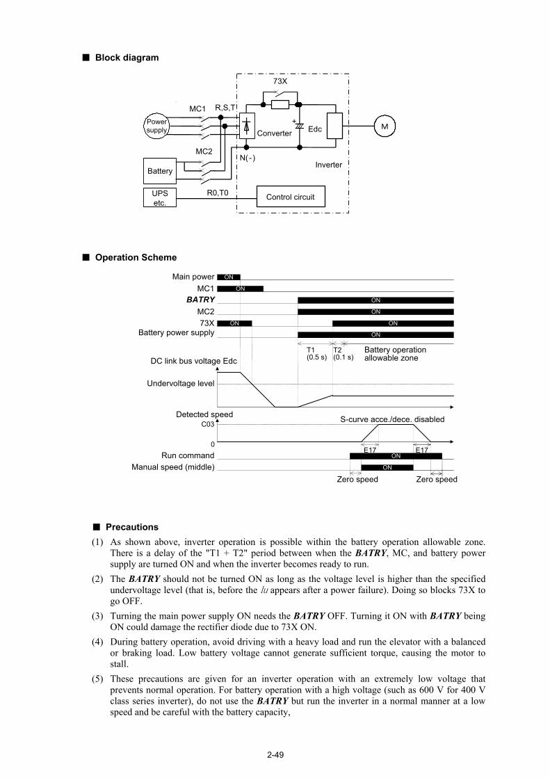
2-49
Block diagram
73X
MC2
R,S,T
N(- )
Battery
R0,T0 Control circuitUPSetc.
MC1
MEdcConverterPowersupply
Inverter
+
Operation Scheme
Main powerMC1
BATRYMC273X
Battery power supply
DC link bus voltage Edc
Run commandManual speed (middle)
Detected speed
Undervoltage level
C03
T1(0.5 s)
T2(0.1 s)
Battery operationallowable zone
Zero speed Zero speed
ON
ON
ON
ON
ON
ON
ON
ON
ON
S-curve acce./dece. disabled
E17 E170
Precautions (1) As shown above, inverter operation is possible within the battery operation allowable zone.
There is a delay of the "T1 + T2" period between when the BATRY, MC, and battery power supply are turned ON and when the inverter becomes ready to run.
(2) The BATRY should not be turned ON as long as the voltage level is higher than the specified undervoltage level (that is, before the lu appears after a power failure). Doing so blocks 73X to go OFF.
(3) Turning the main power supply ON needs the BATRY OFF. Turning it ON with BATRY being ON could damage the rectifier diode due to 73X ON.
(4) During battery operation, avoid driving with a heavy load and run the elevator with a balanced or braking load. Low battery voltage cannot generate sufficient torque, causing the motor to stall.
(5) These precautions are given for an inverter operation with an extremely low voltage that prevents normal operation. For battery operation with a high voltage (such as 600 V for 400 V class series inverter), do not use the BATRY but run the inverter in a normal manner at a low speed and be careful with the battery capacity,

2-50
C04 to C11 Multistep Speed F01 (Speed Command)
C04 through C11 specify zero speed to high speed for multistep speed change. Turning SS1, SS2 and SS4 assigned to digital input terminals ON and OFF changes the speed. - Data setting range: 0.00 to 3600 (r/min)
For details, refer to function code F01.
C20 Jogging Operation Speed H54 (Acceleration time, Jogging) H55 (Deceleration time, Jogging)
C20 specifies the jogging operation speed. - Data setting range: 0.00 to 3600 (r/min)
Jogging operation The terminal command JOG can be assigned to a programmable input terminal by setting "10." With the JOG being ON, turning FWD or REV ON starts the jogging operation regardless of the F01 setting. In jogging operation, the acceleration and deceleration times specified by H54 and H55 apply, respectively. The torque control disables this function even with JOG being ON.
Turning the JOG ON when the inverter is running in ordinary operation cannot switch the inverter to jogging operation. Stop the inverter once and switch to jogging operation. A run command (e.g., FWD) and JOG command should be entered within 100 ms. Note that if the input of a run command precedes that of the JOG command, the inverter runs in ordinary operation until the input of the JOG command.

2-51
C21 Speed Command Unit
C21 specifies units for setting the speed. Data for C21 and the specified units are as follows.
Data for C21 Speed command unit
0 r/min
1 m/min
2 Hz
Changing C21 data converts previously specified function code data into a newly specified unit for display. It also modifies the setting range automatically.
Changing the C21 data requires modifying the data of some function codes. For details, refer to page 2-12.
Relational equations between (Hz) and other units
1. (r/min) and (Hz)
PeHzr ][120min]/[ ×=
2. (m/min) and (Hz)
PeHz
NVm ][120
maxmaxmin]/[ ××=
Where,
Pe :Motor, No. of poles (P01) (poles) maxN :Maximum speed (F03) (r/min) maxV :Elevator parameter, Elevator speed (L31) (m/min)
As shown in the above equations, changing the data of any of function codes P01, F03, and L31 automatically modifies the inverter's speed settings specified in r/min or m/min.

2-52
C31 to C33 Analog Input Adjustment for [12] (Offset) (Gain) (Filter time constant) C36 to C38 Analog Input Adjustment for [C1] (Offset) (Gain) (Filter time constant) C41 to C43 Analog Input Adjustment for [V2] (Offset) (Gain) (Filter time constant)
These function codes specify the gain, offset, and filter time constant for analog input terminals.
Offset (C31, C36, and C41) These function codes specify the offset adjustment for analog input voltage or current. - Data setting range: -100.0 to 100.0 (%)
Gain (C32, C37, and C42) These function codes specify the gain adjustment for analog input voltage or current. - Data setting range: 0.00 to 200.00 (%)
Command values The following formula indicates the relationship between the command value, gain (%), offset (%), and analog input (%).
Command value = (Analog input - Offset) × Gain × Reference value Where, the analog input -100 to 100% corresponds to -10 to 10 V in voltage input, and 0 to 100%, to 4 to 20 mA in current input. The table below lists the reference values and limits.
Commands Reference values Limits
Reference speed (pre-ramp) Maximum speed Maximum speed × -100 to 100%
Reference torque current 200% of overload capacity Inverter rated current × -400 to 400%
Reference torque bias 100% of motor rated torque Motor rated torque × -200 to 200% Setting F01 to "1: Analog speed command (Not reversible)" limits the reference speed (pre-ramp) at 0% or 100% of the maximum speed.
×
C42
Gain
C41
+
-
Offset
C43
Filter timeconstant
×
C37C36
+
-
C38
×
C32C31
+
-
C33
Polarity±10 V = ±100%No polarity0 to 10 V = 0 to 100%
[12]Analog speed command
Polarity±10 V = ±100%No polarity0 to 10 V = 0 to 100%
[V2]Analog speed command
[C1]Analog speed command
4 to 20 mA = 0 to 100%
E61
Analog inputfor [12]
1, 2
3
4
E63
Analog inputfor [V2]
1, 2
3
4
+
+
++
+
++
+
+
E62
Analog inputfor [C1]
1
3
4
Limit
Limit
Limit
Referencetorque bias
Referencetorque
Reference speed(pre-ramp)
Simplified Block Diagram of Analog Inputs

2-53
Operation examples The following graphs show operation examples using the gain and offset effects. Current input or non-polar voltage input makes shaded areas invalid (as 0 V or 4 mA), and polar voltage input makes the shaded areas valid.
Analog input command
Analoginput
100%reference
point
-10V
-100%reference
point
0%
200% gain
200%reference
point
-200%reference
point
100% gain
50% gain
Analog input command
Analoginput
100%reference
point
0V(4 mA)
10V(20 mA)
-10V
-100%reference
point
0%
-50% offset
200%reference
point
-200%reference
point
0% offset
60% offset
Analog input command
Analoginput
100%reference
point
-10V
-100%reference
point
0%
80% gain and-60% offset
200%reference
point
-200%reference
point
100% gain and0% offset
200% gain and40% offset
Adjust gain with 0% offset Adjust offset with 100% gain Adjust offset and gain
-11V 11V -11V 11V-11V
11V10V(20 mA)
10V(20 mA)
0V(4 mA)
0V(4 mA)
Filter time constant (C33, C38, and C43) These function codes specify the filter time constant for analog input voltage or current on terminals [12], [C1] and [V2]. Increasing the filter time constant delays the response from machinery or equipment, and that is, the time constant should be specified with considering response speed. If the input voltage fluctuates due to noise, large filter time constant releases it. - Data setting range: 0.000 to 5.000 (s)

2-54
2.2.4 P codes (Motor parameters)
P01 Motor (No. of poles)
P01 specifies the number of poles of the motor. The following formula is used for the conversion.
(Hz)Frequency × poles of No.
120 (r/min) speedMotor =
- Data setting range: 2 to 100 (poles)
Changing the P01 data requires modifying the data of some function codes. For details, refer to page 2-12.
P02 Motor (Rated capacity) P02 specifies the rated capacity of the motor. Enter the rated value shown on the nameplate of the motor. - Data setting range: 0.01 to 55.00 (kW)
P03 Motor (Rated current) P03 specifies the rated current of the motor. Enter the rated value shown on the nameplate of the motor. - Data setting range: 0.00 to 500.0 (A)
P04 Motor (Auto-tuning) This function automatically detects the motor parameters and saves them in the inverter’s internal memory. Basically, you do not need to perform tuning if you use a Fuji standard motor with a standard connection with the inverter. P04 is only for asynchronous motors. For synchronous motors, the magnetic pole position offset tuning (L03) applies. In any of the following cases, perform auto-tuning. This is because you may not obtain the best performance under the PG vector control since the motor parameters are different from that of Fuji standard motors. • The motor to be driven is made by other manufacturer or is a non-standard motor. • Cabling between the motor and the inverter is long. • A reactor is inserted between the motor and the inverter.
For details of auto tuning, refer to the FRENIC-Lift Instruction Manual (INR-SI47-1038-E), Section 4.1.3 "Preparation before running the motor for a test -- Setting function code data."

2-55
P06 Motor (No-load current) P07 Motor (%R1) P08 Motor (%X)
These function codes specify no-load current, %R1, and %X. Obtain the appropriate values from the test report of the motor or by calling the manufacturer of the motor. If you perform auto tuning, these parameters are automatically set as well.
No-load current (P06) Enter the value obtained from the motor manufacturer. - Data setting range: 0.00 to 500.0 (A)
%R1 (P07) Enter the value calculated by the following formula.
(%) 100× )I×3(/V
R1CableR1%R1 +=
where, R1: Primary resistance of the motor (Ω) Cable R1: Resistance of the output cable (Ω) V: Rated voltage of the motor (V) I: Rated current of the motor (A)
- Data setting range: 0.00 to 50.00 (%)
%X (P08) Enter the value calculated by the following formula.
(%) 100× )I×3(/V
XCableXM)(X2/XM×X2X1%X +++=
X1: Primary leakage reactance of the motor (Ω) X2: Secondary leakage reactance of the motor (converted to primary) (Ω) XM: Exciting reactance of the motor (Ω) Cable X: Reactance of the output cable (Ω) V: Rated voltage of the motor (V) I: Rated current of the motor (A)
- Data setting range: 0.00 to 50.00 (%)
For reactance, choose the value at the rated speed (F04).

2-56
P09 Motor (Slip comp. driving gain) P10 Motor (Slip comp. braking gain)
P09 and P10 specify the slip compensation gain in percentage to the rated slip (P12) at the driving and braking sides, respectively. - Data setting range: (P09, P10): 0.0 to 200.0 (%)
P12 Motor (Rated slip) P12 specifies the rated slip frequency of the motor. - Data setting range: 0.00 to 15.00 (Hz)
The rated slip frequency is calculated with the following formula.
r/min)( speed sSynchronou
(r/min) speed Rated - r/min)( speed sSynchronou(Hz)frequency Rated (Hz)frequency slip Rated ×=

2-57
2.2.5 H codes (High performance functions)
H03 Data Initialization H03 initializes the current function code settings to the factory defaults. To change the H03 data with the keypad, it is necessary to press and keys or and keys simultaneously.
Data for H03 Function
0 Disable initialization. (Settings manually made by the user will be retained.)
1 Initialize all function code data to the factory defaults.
Upon completion of the initialization, the data of function code H03 is reset to "0" (default setting).
H04 Auto-resetting (Times) H05 Auto-resetting (Reset interval)
H04 and H05 specify the auto-resetting function. Even if any protective function subject to auto-resetting is activated and the inverter enters the forced-to-stop state (tripped state), the inverter will automatically attempt to reset the tripped state and restart without issuing an alarm (for any faults). If the protective function works in excess of the times specified by H04, the inverter will issue an alarm (for any faults) and not attempt to auto-reset the tripped state.
Listed below are the recoverable alarm statuses to be auto-reset.
Alarm status Alarm on LED monitor Alarm status Alarm on LED monitor
Instantaneous overcurrent protection 0c1, 0c2, 0c3 Motor overheated 0h4
Overvoltage protection 0u1, 0u2, 0u3 Motor overloaded 0l1
Heat sink overheated 0h1 Inverter overloaded 0lu
Inverter overheated 0h3 Overspeed 0s
Undervoltage detected lu Speed excessive deviation ere
Number of auto-resetting times (H04) H04 specifies the number of auto-resetting times for automatically escaping the tripped state. If the protective function is activated more than the specified auto-resetting times, the inverter issues an alarm (for any faults) and does not attempt to escape the tripped state. - Data setting range: 0 (disable) 1 to 10 (times)
If the "auto-resetting" function has been specified, the inverter may automatically restart and run the motor stopped due to a trip fault, depending on the cause of the tripping.
Design the machinery so that human body and peripheral equipment safety is ensured even when the auto-resetting succeeds.
Otherwise an accident could occur.

2-58
Reset interval (H05) H05 specifies the interval time to attempt performing auto-resetting the tripped state. Refer to the timing scheme diagram below. - Data setting range: 0.5 to 20.0 (s) Operation timing scheme
Timing scheme for failed auto-resetting (No. of resetting times: 3)
The auto-resetting state can be monitored from the external equipment via a digital output terminal to which the TRY is assigned by setting "26" with E20 to E24 and E27.
Auto-tuning and polar offset tuning disable the auto-resetting functions.
H06 Cooling Fan Control H06 specifies the ON-duration of the cooling fan. To prolong the life of the cooling fan and reduce fan noise during running, the cooling fan stops when the temperature inside the inverter drops below a certain level. Setting the H06 data to 0.0 automatically turns the cooling fan ON/OFF depending upon the temperature even when the inverter is running. The cooling fan does not restart for 10 seconds after stopping. - Data setting range: 0.0 (Auto ON/OFF depending upon temperature) 0.5 to 10.0 (min.) 999 (Disable. Always ON)
The cooling fan state can be monitored via a digital output terminal to which the FAN is assigned by setting "25."

2-59
H18 Torque Control F42 (Control Mode)
H18 specifies control modes. Speed control mode and torque control mode are available.
Data for H18 Function
0 Disable: Speed control mode
1 Enable: Torque control mode Analog torque control Analog input to input terminal [12], [C1] or [V2] specifies the torque current command when the command is assigned to the input terminal by setting any of E61 to E63 data to "3." In torque control, the torque current command and motor load determine the speed and rotational direction.
Analog input (input voltage to terminals [12] and [V2] and input current to terminal [C1]) is set by offset, gain and filter. For details, refer to function codes C31 to C33, C36 to C38 and C41 to C43.
H26 PTC Thermistor (Mode) H27 PTC Thermistor (Level)
These function codes protect the motor from overheating or output an alarm signal using the PTC (Positive Temperature Coefficient) thermistor embedded in the motor.
PTC thermistor (Mode) (H26) Selects the function operation mode (protection or alarm) for the PTC thermistor as shown below.
Data for H26 Action
0 Disable
1 Enable
When the voltage sensed by the PTC thermistor exceeds the detection level, the motor protective function (alarm 0h4 ) is triggered, causing the inverter to enter an alarm stop state.
2 Enable
When the voltage sensed by the PTC thermistor exceeds the detection level, a motor alarm signal is output but the inverter continues running.
You need to assign the motor overheat protection THM to one of the digital output terminals beforehand, by which a temperature alarm condition can be detected by the thermistor (PTC) (function code data = 56).

2-60
PTC thermistor (Level) (H27) Specifies the detection level for the temperature (expressed in voltage) sensed by PTC thermistor. - Data setting range: 0.00 to 5.00 (V)
The temperature at which the overheating protection is to be activated depends on the characteristics of the PTC thermistor. The internal resistance of the thermistor will significantly change at the alarm temperature. The detection level (voltage) is specified based on the change of internal resistance.
Suppose that the resistance of PTC thermistor at alarm temperature Rp, the detection (voltage) level Vv2 is calculated by the equation below. Set the result Vv2 to function code H27.
Substitute the internal resistance of the PTC thermistor at the alarm temperature with Rp to obtain Vv2.
(V)10×
pR22k
p×R22k27k
pR22k
p×R22k
VV
++
+=2
Connect the PTC thermistor as shown below. The voltage that is obtained by dividing the input voltage to the terminal [V2] with a set of internal resistors is compared with the preset detection level voltage (H27).

2-61
H30 Communications Link Operation
H30 specifies the sources of a speed command and run command--"inverter itself" and "computers or PLCs via the RS485 communications link or the CAN communications link," and setting means of speed command and run command.
RS485
CAN
Link functionselection
Terminal [LE] unassignedTerminal [LE] ON
=0
=1
y99
H30
Loader linkfunctionselection
Inverter Commandselection
Command sources selectable
Command sources Description
Inverter itself Command sources except RS485 communications link and CAN communications link Speed command:Source specified by F01 (e.g., multistep speed command) Run command: Via the keypad or digital input terminals
RS485 communications link Via the standard RJ-45 port used for connecting keypad
CAN communications link Via CAN communications link

2-62
Command sources specified by H30
Data for H30 Speed command Run command Reference torque bias
0 Inverter itself Inverter itself Inverter itself
1 Via RS485 communications link
Inverter itself Inverter itself
2 Inverter itself Via RS485 communications link
Inverter itself
3 Via RS485 communications link
Via RS485 communications link
Inverter itself
4 Via CAN communications link
Inverter itself Inverter itself
5 Inverter itself Via CAN communications link
Inverter itself
6 Via CAN communications link
Via CAN communications link
Inverter itself
7 Inverter itself Inverter itself Via RS485 communications link
8 Via RS485 communications link
Inverter itself Via RS485 communications link
9 Inverter itself Via RS485 communications link
Via RS485 communications link
10 Via RS485 communications link
Via RS485 communications link
Via RS485 communications link
11 Inverter itself Inverter itself Via CAN communications link
12 Via CAN communications link
Inverter itself Via CAN communications link
13 Inverter itself Via CAN communications link
Via CAN communications link
14 Via CAN communications link
Via CAN communications link
Via CAN communications link
For details, refer to Chapter 1 "BLOCK DIAGRAMS FOR CONTROL LOGIC" and the
RS485 Communication User's Manual or CAN Communication User's Manual.
When the LE terminal command is assigned to a digital input terminal and the terminal is ON, the settings of function code H30 is effective. When the terminal is OFF, the settings of the code are ineffective, and both speed commands and run commands specified from the inverter itself take control.
H42 Capacitance of DC Link Bus Capacitor H42 displays the measured capacitance of the DC link bus capacitor (reservoir capacitor). - Data setting range: 0 to 65535
H43 Cumulative Run Time of Cooling Fan H43 displays the cumulative run time of the cooling fan. - Data setting range: 0 to 65535

2-63
H47 Initial Capacitance of DC Link Bus Capacitor
H47 displays the initial value of the capacitance of the DC link bus capacitor (reservoir capacitor). - Data setting range: 0 to 65535
H48 Cumulative Run Time of Capacitors on Printed Circuit Board H48 displays the cumulative run time of capacitors on the printed circuit boards. - Data setting range: 0 to 65535
H54 Acceleration Time (Jogging)
H55 Deceleration Time (Jogging)
H54 and H55 specify the acceleration and deceleration times for jogging operation, respectively. The acceleration time is the one required for accelerating from 0.00 to the maximum speed (r/min) and the deceleration time, for decelerating from the maximum speed to 0.00 (r/min). - Data setting range: 0.00 to 99.9 (s)
For details, refer to function code C20.
H56 Deceleration Time for Forced to Decelerate
H56 specifies the deceleration time for forced deceleration. The deceleration time is the one required for decelerating from the maximum speed to 0.00 (r/min). - Data setting range: 0.00 to 99.9 (s) Forced to decelerate The DRS command can be assigned to a general-purpose, programmable input terminal by setting "66." The DRS should be ON when the inverter is running. Turning the DRS OFF decelerates the speed during the time specified by H56 and then shuts down the inverter output upon detection of a stop speed. Once the DRS goes OFF, the inverter no longer runs (that is, the forced-to-decelerate mode will no longer be canceled) until the run command goes OFF and the inverter output is shut down. The operation scheme is shown below.
High speed
Speed
TimeZero speed
Stop speed
ONFWD
SS1
SS2
ON
ON
SS4 ON
Zero speedcommand
High speedcommand
Forced todecelerate
Outputshut down
DRS ON ONOFFForced to decelerate mode
OFF ON
High speedcommand
Slope to decelerate by H56

2-64
H65 Starting Speed (Soft start time) F23 (Starting Speed)
H65 specifies the acceleration time until the speed reaches the starting speed. The specified time is the one required for accelerating from 0.00 to the starting speed (r/min).
- Data setting range: 0.0 to 60.0 (s) For details, refer to function code F23.
H66 Stop Speed (Detection method) F25 (Stop Speed)
H66 specifies the stop speed detection method.
Data for H66 Detection method
0 Use the detected speed.
1 Use the reference speed (final).
For details, refer to the description of function code F25.
H67 Stop Speed (Holding time) F25 (Stop Speed)
H67 specifies the holding time of the stop speed. - Data setting range: 0.00 to 10.00 (s)
For details, refer to function code F25.
H74 Speed Agreement (Hysteresis) H75 Speed Agreement (OFF delay time)
The DSAG signal can be assigned to a general-purpose, programmable output terminal by setting "71." The DSAG comes ON regardless of the status of a run command when the difference between the commanded and detected speeds is within the hysteresis band specified by H74. The ON-to-OFF delay circuit is available for chattering prevention. If the difference is larger than the allowable band specified by H74 continuously for the time specified by H75, then the DSAG signal goes OFF. No OFF-to-ON delay function is available. Selecting the torque control disables this function. - Data setting range (H74): 0.00 to 3600 (r/min) - Data setting range (H75): 0.00 to 1.00 (s)
L09: Filtertime constantfor referencespeed (final)
+
-
Speedregulator
S-curve rampcontroller
Referencespeed
(pre-ramp)
Detectedspeed
OFFON
0Negativedeviation
Positivedeviation
Deviation
Speed agreementsignal DSAG
H74: Hysteresis
OFF delay
H74: Hysteresis H74: HysteresisH75: Speedagreement
OFF delay time
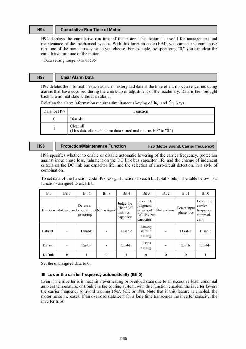
2-65
H94 Cumulative Run Time of Motor
H94 displays the cumulative run time of the motor. This feature is useful for management and maintenance of the mechanical system. With this function code (H94), you can set the cumulative run time of the motor to any value you choose. For example, by specifying "0," you can clear the cumulative run time of the motor. - Data setting range: 0 to 65535
H97 Clear Alarm Data H97 deletes the information such as alarm history and data at the time of alarm occurrence, including alarms that have occurred during the check-up or adjustment of the machinery. Data is then brought back to a normal state without an alarm. Deleting the alarm information requires simultaneous keying of and keys.
Data for H97 Function
0 Disable
1 Clear all (This data clears all alarm data stored and returns H97 to "0.")
H98 Protection/Maintenance Function F26 (Motor Sound, Carrier frequency)
H98 specifies whether to enable or disable automatic lowering of the carrier frequency, protection against input phase loss, judgment on the DC link bus capacitor life, and the change of judgment criteria on the DC link bus capacitor life, and the selection of short-circuit detection, in a style of combination.
To set data of the function code H98, assign functions to each bit (total 8 bits). The table below lists functions assigned to each bit.
Bit Bit 7 Bit 6 Bit 5 Bit 4 Bit 3 Bit 2 Bit 1 Bit 0
Function Not assigned Detect a short-circuit at startup
Not assigned
Judge the life of DC link bus capacitor
Select life judgment criteria of DC link buscapacitor
Not assigned Detect input phase loss
Lower the carrier frequency automati- cally
Data=0 - Disable - Disable Factory default setting
- Disable Disable
Data=1 - Enable - Enable User's setting - Enable Enable
Default 0 1 0 1 0 0 0 1
Set the unassigned data to 0.
Lower the carrier frequency automatically (Bit 0) Even if the inverter is in heat sink overheating or overload state due to an excessive load, abnormal ambient temperature, or trouble in the cooling system, with this function enabled, the inverter lowers the carrier frequency to avoid tripping (0h1, 0h3, or 0lu). Note that if this feature is enabled, the motor noise increases. If an overload state kept for a long time transcends the inverter capacity, the inverter trips.

2-66
Detect input phase loss (lin ) (Bit 1) Upon detecting an excessive stress inflicted on the apparatus connected to the main circuit because of phase loss or inter-phase imbalance in the 3-phase power supplied to the inverter, this feature stops the inverter and displays an alarm lin .
In configurations where only a light load is driven or a DC reactor is connected, a phase loss or an inter-phase imbalance may not be detected because of the relatively small stress on the apparatus connected to the main circuit.
Select life judgment criteria of DC link bus capacitor (Bit 3) H98 allows you to select the criteria for judging the life of the DC link bus capacitor/s (reservoir capacitor/s) between factory default setting and your own choice.
Before specifying the criteria of your own choice, measure and confirm the reference level in advance. For details, refer to the FRENIC-Lift Instruction Manual (INR-SI47-1038-E), Chapter 7 "MAINTENANCE AND INSPECTION."
Judge the life of DC link bus capacitor (Bit 4) Whether the DC link bus capacitor (reservoir capacitor) has reached its life is determined by measuring the length of time for discharging after power off. The discharging time is determined by the capacitance of the DC link bus capacitor and the load inside the inverter. Therefore, if the load inside the inverter fluctuates significantly, the discharging time cannot be accurately measured, and as a result, it may be mistakenly determined that the life has been reached. To avoid such an error, you can disable the judgment on the life of the DC link bus capacitor. Load may vary significantly in the following cases. Disable the judgment on the life during operation, and either conduct the measurement with the judgment enabled under appropriate conditions during periodical maintenance or conduct the measurement under the actual use conditions. • Auxiliary input for control power is used • An option card is used • Another inverter or equipment such as a PWM converter is connected to the terminals of the DC
link bus. For details, refer to the FRENIC-Lift Instruction Manual (INR-SI47-1038-E), Chapter 7
"MAINTENANCE AND INSPECTION."
Detect a short-circuit at startup (Bit 6) H98 selects whether to enable or disable the short-circuit detection that checks the output wirings for a short-circuit when the inverter main power is turned ON. Enabling the short-circuit detection may mistakenly detect a short-circuit when the motor impedance is low. If it happens, disable the detection.
H99 Password Protection F00 (Data Protection)
H99 specifies a password. - Data setting range: 0000H (Disable password protection) 0001H to FFFFH (Enable password protection)
For details, refer to function code F00.
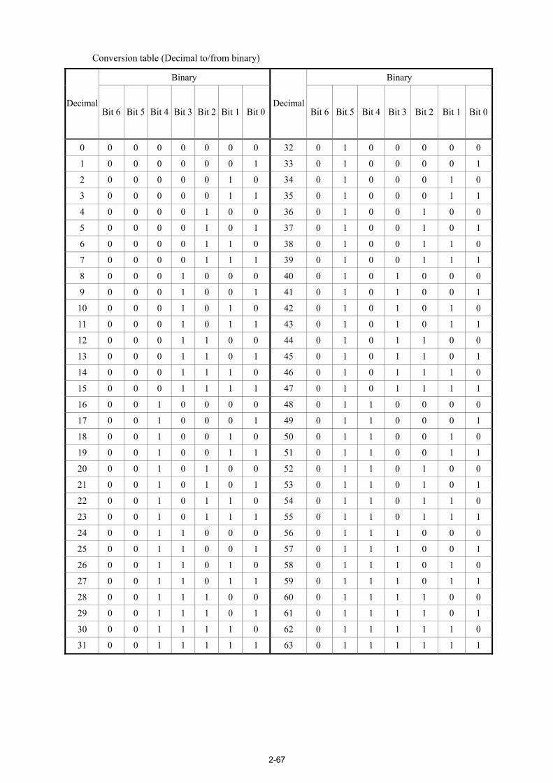
2-67
Conversion table (Decimal to/from binary)
Binary Binary
Decimal Bit 6 Bit 5 Bit 4 Bit 3 Bit 2 Bit 1 Bit 0
DecimalBit 6 Bit 5 Bit 4 Bit 3 Bit 2 Bit 1 Bit 0
0 0 0 0 0 0 0 0 32 0 1 0 0 0 0 0
1 0 0 0 0 0 0 1 33 0 1 0 0 0 0 1
2 0 0 0 0 0 1 0 34 0 1 0 0 0 1 0
3 0 0 0 0 0 1 1 35 0 1 0 0 0 1 1
4 0 0 0 0 1 0 0 36 0 1 0 0 1 0 0
5 0 0 0 0 1 0 1 37 0 1 0 0 1 0 1
6 0 0 0 0 1 1 0 38 0 1 0 0 1 1 0
7 0 0 0 0 1 1 1 39 0 1 0 0 1 1 1
8 0 0 0 1 0 0 0 40 0 1 0 1 0 0 0
9 0 0 0 1 0 0 1 41 0 1 0 1 0 0 1
10 0 0 0 1 0 1 0 42 0 1 0 1 0 1 0
11 0 0 0 1 0 1 1 43 0 1 0 1 0 1 1
12 0 0 0 1 1 0 0 44 0 1 0 1 1 0 0
13 0 0 0 1 1 0 1 45 0 1 0 1 1 0 1
14 0 0 0 1 1 1 0 46 0 1 0 1 1 1 0
15 0 0 0 1 1 1 1 47 0 1 0 1 1 1 1
16 0 0 1 0 0 0 0 48 0 1 1 0 0 0 0
17 0 0 1 0 0 0 1 49 0 1 1 0 0 0 1
18 0 0 1 0 0 1 0 50 0 1 1 0 0 1 0
19 0 0 1 0 0 1 1 51 0 1 1 0 0 1 1
20 0 0 1 0 1 0 0 52 0 1 1 0 1 0 0
21 0 0 1 0 1 0 1 53 0 1 1 0 1 0 1
22 0 0 1 0 1 1 0 54 0 1 1 0 1 1 0
23 0 0 1 0 1 1 1 55 0 1 1 0 1 1 1
24 0 0 1 1 0 0 0 56 0 1 1 1 0 0 0
25 0 0 1 1 0 0 1 57 0 1 1 1 0 0 1
26 0 0 1 1 0 1 0 58 0 1 1 1 0 1 0
27 0 0 1 1 0 1 1 59 0 1 1 1 0 1 1
28 0 0 1 1 1 0 0 60 0 1 1 1 1 0 0
29 0 0 1 1 1 0 1 61 0 1 1 1 1 0 1
30 0 0 1 1 1 1 0 62 0 1 1 1 1 1 0
31 0 0 1 1 1 1 1 63 0 1 1 1 1 1 1

2-68
Binary Binary
Decimal Bit 6 Bit 5 Bit 4 Bit 3 Bit 2 Bit 1 Bit 0 Decimal Bit 6 Bit 5 Bit 4 Bit 3 Bit 2 Bit 1 Bit 0
64 1 0 0 0 0 0 0 96 1 1 0 0 0 0 0
65 1 0 0 0 0 0 1 97 1 1 0 0 0 0 1
66 1 0 0 0 0 1 0 98 1 1 0 0 0 1 0
67 1 0 0 0 0 1 1 99 1 1 0 0 0 1 1
68 1 0 0 0 1 0 0 100 1 1 0 0 1 0 0
69 1 0 0 0 1 0 1 101 1 1 0 0 1 0 1
70 1 0 0 0 1 1 0 102 1 1 0 0 1 1 0
71 1 0 0 0 1 1 1 103 1 1 0 0 1 1 1
72 1 0 0 1 0 0 0 104 1 1 0 1 0 0 0
73 1 0 0 1 0 0 1 105 1 1 0 1 0 0 1
74 1 0 0 1 0 1 0 106 1 1 0 1 0 1 0
75 1 0 0 1 0 1 1 107 1 1 0 1 0 1 1
76 1 0 0 1 1 0 0 108 1 1 0 1 1 0 0
77 1 0 0 1 1 0 1 109 1 1 0 1 1 0 1
78 1 0 0 1 1 1 0 110 1 1 0 1 1 1 0
79 1 0 0 1 1 1 1 111 1 1 0 1 1 1 1
80 1 0 1 0 0 0 0 112 1 1 1 0 0 0 0
81 1 0 1 0 0 0 1 113 1 1 1 0 0 0 1
82 1 0 1 0 0 1 0 114 1 1 1 0 0 1 0
83 1 0 1 0 0 1 1 115 1 1 1 0 0 1 1
84 1 0 1 0 1 0 0 116 1 1 1 0 1 0 0
85 1 0 1 0 1 0 1 117 1 1 1 0 1 0 1
86 1 0 1 0 1 1 0 118 1 1 1 0 1 1 0
87 1 0 1 0 1 1 1 119 1 1 1 0 1 1 1
88 1 0 1 1 0 0 0 120 1 1 1 1 0 0 0
89 1 0 1 1 0 0 1 121 1 1 1 1 0 0 1
90 1 0 1 1 0 1 0 122 1 1 1 1 0 1 0
91 1 0 1 1 0 1 1 123 1 1 1 1 0 1 1
92 1 0 1 1 1 0 0 124 1 1 1 1 1 0 0
93 1 0 1 1 1 0 1 125 1 1 1 1 1 0 1
94 1 0 1 1 1 1 0 126 1 1 1 1 1 1 0
95 1 0 1 1 1 1 1 127 1 1 1 1 1 1 1

2-69
2.2.6 y codes (Link functions) Following is the applicable devices and that general information. (1) Multi-function keypad (option)
The multi-function keypad (option) allows you to run and monitor the inverter. There is no need to set the y codes.
(2) FRENIC Loader Using your PC running FRENIC Loader, you can monitor the inverter’s running status information, edit function codes, and test-run the inverters.
(3) Host equipment The inverter can be managed and monitored by connecting host equipment such as a PC and PLC to the inverter. Modbus RTU* is available for communications protocols.
*Modbus RTU is a protocol established by Modicon, Inc.
For details, refer to the RS485 Communication User's Manual.
y01 to y10 RS485 Communication Station address (y01)
These function codes specify the station address for the RS485 communications link. The table below lists the protocols and the station address setting ranges.
Protocol Station address Broadcast address
Modbus RTU protocol 1 to 247 0
SX protocol (Loader protocol) 1 to 255 None
- If any wrong address beyond the above range is specified, no response is returned since the inverter will be unable to receive any enquiries except the broadcast message.
- To use FRENIC Loader, set the station address that matches the connected PC.
Communications error processing (y02) Set the operation performed when an RS485 communications error has occurred. RS485 communications errors contain logical errors such as address error, parity error, framing error, and transmission error, and physical errors such as communication break error set by y08. In each case, these are judged as an error only when the inverter is running while the operation command or reference speed (pre-ramp) has been set to the configuration specified through RS485 communication. When neither the operation command nor reference speed (pre-ramp) command is issued through RS485 communication or the inverter is not running, error occurrence is not recognized.
Data for y02 Function
0 Immediately trip after showing an RS485 communications error er8. (The inverter stops with alarm issue.)
1 Run during the time set on the error processing timer (y03), display an RS485 communications error er8, and then stop operation. (The inverter stops with alarm issue.)
2 Retry transmission during the time set on the error processing timer (y03). If communications link is recovered, continue operation. Otherwise, display an RS485 communications error er8 and stop operation. (The inverter stops with alarm issue.)
3 Continue to run even when a communications error or a communication break error occurs.
For details, refer to the RS485 Communication User's Manual.

2-70
Error processing time (y03) Function code y03 specifies an error processing time. When the specified time has elapsed because of no response on other end etc., if a response request was issued, the inverter interprets that an error occurs. See the section of "No-response error detection time (y08)." - Data setting range: 0.0 to 60.0 (s)
Baud rate (y04)
Data for y04 Baud rate
0 2,400 bps
1 4,800 bps
2 9,600 bps
3 19,200 bps
Select the transmission speed for RS485 communication. - Setting for FRENIC Loader:
Set the same transmission speed as that specified by the connected PC.
4 38,400 bps
Data length (y05)
Data for y05 Data length
0 8 bits
Select the character length for transmission. - Setting for FRENIC Loader:
Loader automatically sets the length in 8 bits. The same applies to the Modbus RTU protocol. 1 7 bits
Parity check (y06)
Data for y06 Parity
0 None
1 Even parity
2 Odd parity
Select the property of the parity bit. - Setting for FRENIC Loader:
Loader automatically sets the even parity. - Setting for the Modbus RTU protocol: Setting "0" automatically determines 2 stop bits, and
setting "1," "2," or "3," a single stop bit. 3 None
Stop bits (y07)
Data for y07 Stop bit(s)
0 2 bits
Select the number of stop bits. - Setting for FRENIC Loader:
No setting is required. Loader automatically sets 1 bit. - Setting for Modbus RTU protocol. No setting is required. 1 1 bit
No-response error detection time (y08)
Data for y08 Function
0 Disable
Set the time interval from the inverter detecting no access until it enters communications error alarm mode due to network failure and processes the communications error. This applies to a mechanical system that always accesses its station within a predetermined interval during communications using the RS485 communication link. For the processing of communications errors, refer to y02.
1 to 60 1 to 60 (s)

2-71
Response latency time (y09) Sets the latency time after the end of receiving a query sent from the host equipment (such as a PC or PLC) to the start of sending the response. This function allows using equipment whose response time is slow while a network requires quick response, enabling the equipment to send a response timely by the latency time setting. - Data setting range: 0.00 to 1.00 (s)
T1 = Latency time + α
Where α is the processing time inside the inverter. This time may vary depending on the processing status and the command processed in the inverter.
For details, refer to the RS485 Communication User's Manual.
When setting the inverter with FRENIC Loader, pay sufficient attention to the performance and/or configuration of the PC and protocol converter such as RS485-RS232C communications level converter. Note that some protocol converters monitor the communications status and switch the send/receive of transmission data by a timer.
Protocol selection (y10)
Data for y10 Protocol
0 Modbus RTU protocol
1 SX protocol (FRENIC Loader protocol)
Select the communications protocol for the standard RS485 port. - Specifying FRENIC Loader to connect to the
inverter can only be made by y10. Select FRENIC Loader (y10 = 1).
2 Reserved for particular manufacturers
y21 CAN Communication (Station address) y22 CAN Communication (Communications error processing) y23 CAN Communication (Error processing time) y24 CAN Communication (Baud rate)
y25 to y32 CAN Communication (User-defined I/O parameters 1 to 8) y33 CAN Communication (Operation)
Function code y21 to y33 are used for CAN communications link setting. For details, refer to the CAN Communication User's Manual.

2-72
y99 Loader Link Function (Mode)
This is a link switching function for FRENIC Loader. Setting the function code data y99 with the loader enable the loader to issue control commands and/or run commands to the inverter. Since the data setting can be done with the loader, no keypad operation is required. While the loader is selected as the source for the run command, if the PC runs out of control and cannot be stopped by a stop command sent from the loader, disconnect the RS485 communications cable from the loader's port, connect a keypad instead, and reset the y99 to "0." This makes the function code H30 to issue control and run commands as shown in the following table. Note that the inverter cannot save the setting of y99. When the inverter is turned off, the data in y99 will back to "0."
Function Data for y99
Control command* Run command
0 Follow H30 Follow H30
1 Via Loader Follow H30
2 Follow H30 Via Loader
3 Via Loader Via Loader * Control command refers to a speed command, torque current command or reference torque bias.
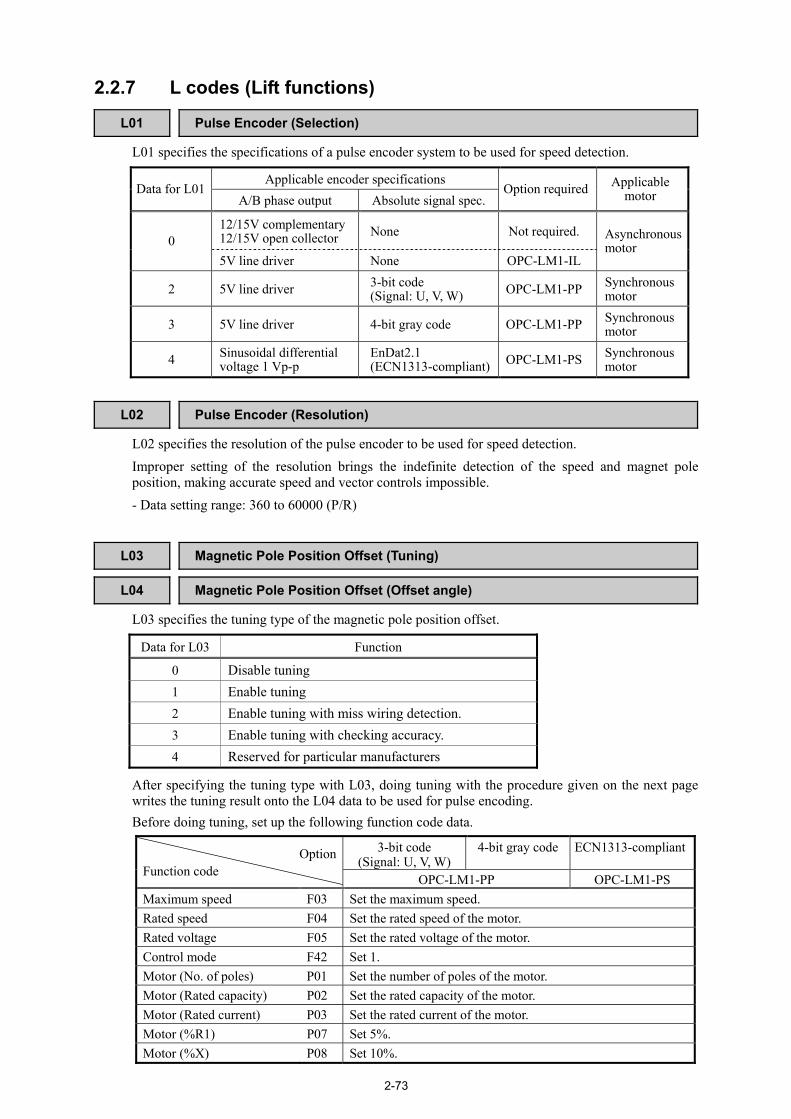
2-73
2.2.7 L codes (Lift functions)
L01 Pulse Encoder (Selection) L01 specifies the specifications of a pulse encoder system to be used for speed detection.
Applicable encoder specifications Data for L01
A/B phase output Absolute signal spec. Option required Applicable
motor
12/15V complementary 12/15V open collector None Not required.
0 5V line driver None OPC-LM1-IL
Asynchronous motor
2 5V line driver 3-bit code (Signal: U, V, W) OPC-LM1-PP Synchronous
motor
3 5V line driver 4-bit gray code OPC-LM1-PP Synchronous motor
4 Sinusoidal differential voltage 1 Vp-p
EnDat2.1 (ECN1313-compliant) OPC-LM1-PS Synchronous
motor
L02 Pulse Encoder (Resolution) L02 specifies the resolution of the pulse encoder to be used for speed detection. Improper setting of the resolution brings the indefinite detection of the speed and magnet pole position, making accurate speed and vector controls impossible. - Data setting range: 360 to 60000 (P/R)
L03 Magnetic Pole Position Offset (Tuning) L04 Magnetic Pole Position Offset (Offset angle)
L03 specifies the tuning type of the magnetic pole position offset.
Data for L03 Function
0 Disable tuning 1 Enable tuning 2 Enable tuning with miss wiring detection. 3 Enable tuning with checking accuracy. 4 Reserved for particular manufacturers
After specifying the tuning type with L03, doing tuning with the procedure given on the next page writes the tuning result onto the L04 data to be used for pulse encoding. Before doing tuning, set up the following function code data.
3-bit code (Signal: U, V, W)
4-bit gray code ECN1313-compliantOptionFunction code OPC-LM1-PP OPC-LM1-PS Maximum speed F03 Set the maximum speed. Rated speed F04 Set the rated speed of the motor. Rated voltage F05 Set the rated voltage of the motor. Control mode F42 Set 1. Motor (No. of poles) P01 Set the number of poles of the motor. Motor (Rated capacity) P02 Set the rated capacity of the motor. Motor (Rated current) P03 Set the rated current of the motor. Motor (%R1) P07 Set 5%. Motor (%X) P08 Set 10%.

2-74
3-bit code
(Signal: U, V, W) 4-bit gray code ECN1313-compliantOption
Function code OPC-LM1-PP OPC-LM1-PS Pulse encoder (Selection) L01 Set 2. Set 3. Set 4. Pulse encoder (Resolution)
L02 Set the number of pulses per revolution of the PG mounted on the motor.
Set 2048 (P/R).
Magnetic pole position offset (Offset angle)
L04 Do tuning of the magnetic pole position offset. The tuning result automatically writes onto L04 data.
ASR (P constant at high speed)
L36 Set 2.00 or less to run the motor by itself.
ASR (P constant at low speed)
L38 Set 2.00 or less to run the motor by itself.
When the target motor is of a synchronous motor, complete the wiring between the inverter, motor, and encoder before doing tuning.
Tuning procedure when L03 = "3: Tuning operation with checking accuracy" (1) Specify the maximum speed (F03), rated speed (F04), rated voltage (F05), control mode (F42),
no. of poles (P01), rated capacity (P02), rated current (P03), %R1 (P07), %X (P08), pulse encoder selection (L01), resolution (L02), ASR P constant at high speed (L36) and ASR P constant at low speed (L38) to match the motor and pulse encoder specifications.
(2) Set function code L03 to "3." When a run command is set, tuning starts. After tuning, the tuning result is written into L04 data. After tuning, the L03 data will be
automatically reset to 0. (3) Enter run forward and run reverse commands to run the motor at the low speed at least one
rotation in the forward and reverse directions, respectively. (Note 1) (4) Turn the power off and then turn it on again to confirm that the motor runs normally. (Note 2)
Note 1: If the motor fails to run normally, the A and B phases of the pulse encoder may be mistakenly connected in wiring. Once shut down the power and correct the wiring of the A and B phases. After parameter-tuning of the motor, do tuning again with the procedure above. Note 2: If the motor fails to run normally, the wiring of the magnetic pole position detection signals may be wrong. Correct the wiring.
For details, refer to the instruction manual of the corresponding option card.
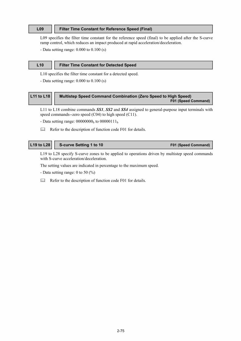
2-75
L09 Filter Time Constant for Reference Speed (Final)
L09 specifies the filter time constant for the reference speed (final) to be applied after the S-curve ramp control, which reduces an impact produced at rapid acceleration/deceleration. - Data setting range: 0.000 to 0.100 (s)
L10 Filter Time Constant for Detected Speed L10 specifies the filter time constant for a detected speed. - Data setting range: 0.000 to 0.100 (s)
L11 to L18 Multistep Speed Command Combination (Zero Speed to High Speed) F01 (Speed Command)
L11 to L18 combine commands SS1, SS2 and SS4 assigned to general-purpose input terminals with speed commands--zero speed (C04) to high speed (C11). - Data setting range: 00000000b to 00000111b
Refer to the description of function code F01 for details.
L19 to L28 S-curve Setting 1 to 10 F01 (Speed Command)
L19 to L28 specify S-curve zones to be applied to operations driven by multistep speed commands with S-curve acceleration/deceleration. The setting values are indicated in percentage to the maximum speed. - Data setting range: 0 to 50 (%)
Refer to the description of function code F01 for details.

2-76
L29 Short Floor Operation (Holding time) L30 Short Floor Operation (Allowable speed)
L29 and L30 specify a short floor operation that applies when a deceleration command is entered during acceleration in a multistep speed operation in order to keep the current high-speed operation and shorten the creep time. The short floor operation can be also used for resetting elevators. Short floor operation holding time (L29) L29 specifies the holding time of a short floor operation. The count of the holding time starts when the speed becomes constant. - Data setting range: 0.00 to 10.00 (s) Allowable speed (L30) L30 specifies the allowable speed, below which a short floor operation can be activated. When the motor is running at the speed less than the one specified by L20 during acceleration in a multistep speed operation, entering a deceleration command activates a short floor operation. - Data setting range: 0.00 to 3600 (r/min) If Reference speed (final) ≤ Allowable speed (L30) when a deceleration command is entered
(1) Upon receipt of a deceleration command, an S-curve operation starts for finishing the current acceleration.
(2) After completion of the S-curve operation, the current speed is kept for the short floor operation holding time (L29).
(3) After the holding time, the inverter decelerates in the specified S-curve operation.
High speed
Time
Speed
Zero speed
ONFWD
SS1
Creep speed
SS2
L29: Short floor operation (Holding time)
ON
L30: Short flooroperation
(Allowable speed)
SS4
E12: Acceleration/deceleration time 5
E13: Acceleration/deceleration time 6L25: S-curve
setting 7
L26: S-curve setting 8
L24: S-curvesetting 6
L19: S-curve setting 1
ON
ON
ON
Zero speedcommand
High speedcommand
Creep speedcommand
Zero speedcommand
L24: S-curvesetting 6
L28: S-curvesetting 10
L28: S-curvesetting 10

2-77
If Reference speed (final) > Allowable speed (L30) and Holding time (L29) ≠ 0.00 when a deceleration command is entered
(1) Upon receipt of a deceleration command, an S-curve operation starts for finishing the current acceleration.
(2) After completion of the S-curve operation, the inverter decelerates in the specified S-curve operation for the creep speed.
High speed
Time
Speed
ON
ON
ON
ON
ON
Zero speed
Creep speed
L30: Short flooroperation
(Allowable speed)
Zero speedcommand
High speedcommand
Creep speedcommand
Zero speedcommand
L19: S-curve setting 1 L28: S-curvesetting 10
L28: S-curvesetting 10
L26: S-curve setting 8
E13: Acceleration/deceleration time 6
L25: S-curvesetting 7
E12: Acceleration/deceleration time 5
L24: S-curvesetting 6
L24: S-curvesetting 6
FWD
SS1
SS2
SS4
If Reference speed (final) > Allowable speed (L30) and Holding time (L29) = 0.00 when a deceleration command is entered
(1) Even if a deceleration command is received, no S-curve operation starts for finishing the current acceleration. (If already in an S-curve operation, the inverter cancels the S-curve operation.)
(2) Immediately the inverter decelerates in the specified S-curve operation for the creep speed.
Time
Speed
ON
ON
ON
ON
ON
High speed
Zero speed
Creep speed
L30: Short flooroperation
(Allowable speed)
Zero speedcommand
High speedcommand
Creep speedcommand
Zero speedcommand
E12: Acceleration/deceleration time 5
E13: Acceleration/deceleration time 6
L26: S-curve setting 8 L28: S-curvesetting 10
L28: S-curvesetting 10
L25: S-curvesetting 7
L24: S-curvesetting 6
L19: S-curve setting 1
FWD
SS1
SS2
SS4

2-78
L31 Elevator Parameter (Speed)
L31 specifies the elevator speed (m/min) relative to the inverter's maximum speed (F03). The elevator speed (L31) can be calculated with the following equation. L31 = Maximum speed (r/min)/Detected speed (r/min) x Elevator rated speed (m/min)
(Example) If the elevator rated speed is 45 m/min, the detected speed is 1350 r/min, and the maximum speed is 1800 r/min: L31 = 1800/1350 x 45 = 60 (m/min)
- Data setting range: 0.01 to 240.00 (m/min)
Changing the elevator parameter (L31) requires modifying the data of other function codes. Refer to page 2-12.
L34 Elevator Parameter (Moving distance in creepless operation) L34 specifies the moving distance of an elevator cage in a creepless operation from its start to end. - Data setting range: 0.0 to 6553.5 (mm)
Creepless operation
If a creepless operation is selected with the function codes listed below, the inverter receives the position of the elevator cage at landing by an external command and generates a speed command pattern that moves the cage by the distance specified by L34 from the current position to land it. Accordingly, the creepless operation eliminates a creep required for general elevator control, decreasing the landing time length.
Function
code Name Data setting range Unit Function
E01 to E08 Command assignment to terminals [X1] to [X8]
64: Start creepless operation
CRPLS --
Turning the associated terminal ON starts creepless operation.
L31 Elevator speed 0.01 to 240.00 m/minThis code specifies the elevator speed relative to the inverter's maximum speed.
L34 Moving distance in creepless operation 0.0 to 6553.5 mm
This code specifies the moving distance of an elevator cage in a creepless operation from its start to end.
Requirements for creepless operation
(1) The elevator system should be equipped with a device that accurately detects the position of an elevator cage, or its equivalent device.
(2) The elevator system should be capable of applying signals issued from the detector (stated in (1) above) to the inverter as a "Start creepless operation" command CRPLS or be capable of modifying speed commands (except zero speed) to zero speed command.
(3) During deceleration, that is, after the start of deceleration, the signal stated in (2) above can be applied to the inverter.
(4) The moving distance from the start of a creepless operation should be 6553.5 mm or less. (5) The elevator speed calculated for L31 should be 240.00 m/min or below. (6) A multistep speed command with S-curve operation should apply for speed control.

2-79
Deceleration point programming and moving distance
Creepless operation requires accurately programming the position of a deceleration point. Given below is a programming method using the calculation result of the moving distance from the start of deceleration to a stop. The moving distance from " Deceleration" to " Stop" in the speed pattern shown below is given by the following equation. Note that N should be equal to or greater than the S-curve zone (N ≥ F03 x (Sc/100 + Sd/100).
TdecVCL ××=60max Equation 1
−+
×+
×=
60000
22
max100max21 2 ScSd
NNSc
NNC Equation 2
Where Vmax: Elevator speed (L31) (m/min) Nmax: Inverter's maximum speed (F03) (r/min) N: Motor speed at the start of deceleration (r/min) Tdec: Deceleration period specified (s) Sc, Sd: S-curve zone specified (%)
Sc
Sd
Tdec
Speed (r/min)
Time t (s)
① Start
② Maximum speed
④ Stop
Sa
Sb
Tacc
③ Deceleration
N
0
The elevator cage moves by distance "L" calculated by equations 1 and 2 when the elevator decelerates from speed "N" during deceleration period "Tdec" within S-curve zone from "Sc" to "Sd," provided that no speed error exists in inverter control. The deceleration point, therefore, should be distance "L" or more before the stop position.
\
Conditions required for starting a creepless operation
When all of the following three conditions are met, a creepless operation starts. (1) A creepless operation command is entered. That is,
- The CRPLS command is turned ON when the CRPLS is assigned to a terminal. - Any speed command (except zero speed) is modified to zero speed when the CRPLS is not
assigned to any terminal. (2) The reference speed (pre-ramp) is 0.00 r/min. (3) The remaining moving distance (the internally calculated moving distance from the start of a
creepless operation) is nonzero.

2-80
Restrictions on creepless operation
(1) The acceleration commanded during a creepless operation will not exceed the specified acceleration.
(2) Do not change the reference speed (pre-ramp) during a creepless operation. (3) After the end of running (including the end of operation due to the protective function triggered
and a coast-to-run command received), turn the CRPLS command OFF. (4) In any of the following cases, the creepless operation is forcedly terminated.
- Such a speed pattern that the speed does not reach 0 after the elevator cage moves the specified moving distance.
- Reference speed (pre-ramp) is nonzero. - Run command is OFF.
After the forced termination, the inverter continues to run with the speed control not involving a creepless operation. No protective function (trip) works. No creepless operation takes place until the inverter stops.
Input timing of a creepless operation command
The graph below shows a basic pattern of a creepless operation using the "Start creepless operation" command CRPLS. The CRPLS command should be given within zone "A" ranging from the end to the start of deceleration. The following example shows deceleration from high speed to zero speed. The waveforms drawn with broken lines show the speed, acceleration and jerk applied when the CRPLS command is given earlier than the ones drawn with full lines.
High speed
Speed
TimeZero speed
ONFWD
SS1
SS2
ON
ON
SS4 ON
Zero speedcommand
High speedcommand
CRPLS ON
Release
Acceleration
Jerk
Theoretical starting point ofcreepless operation
Practical starting point ofcreepless operation
Creepless operation
Zone A: Zero speed command
L24: S-curvesetting 6
L25: S-curvesetting 7
E12: Acceleration/deceleration time 5
E13: Acceleration/deceleration time 6
L28: S-curve setting 10L19: S-curve setting 1
Brake
Maximum speedAcceleration time
Maximum speedDeceleration time
(Calculated by arrival point and movingdistance)
Example of Creepless Operation with CRPLS

2-81
The graph below shows a creepless operation applied when no CRPLS is assigned. Both the creep speed (C07) and zero speed (C04) are 0.00 r/min. To prevent any impact to the load, when the speed changes to zero speed from any other speed, the speed control should be programmed so that the acceleration/deceleration time and S-curve zone will not change.
High speed
Speed
TimeZero speed
ONFWD
SS1
SS2
ON
ON
SS4 ON
ReleaseBrake
Acceleration
Jerk
Creepless operation
Zero speedcommand
High speedcommand
L19: S-curve setting 1
E12: Acceleration/deceleration timer 5
L25: S-curvesetting 7
L24: S-curvesetting 6
E13: Acceleration/deceleration time 6
L28: S-curvesetting 10
Maximum speedAcceleration time
Maximum speedDeceleration time
Theoretical starting point ofcreepless operation
Practical starting point ofcreepless operation
(Calculated by arrival point and movingdistance)
Example of Creepless Operation with CRPLS
Improving the landing position accuracy in a creepless operation
Observing the following rules improves the landing position accuracy (including the repeatability) in a creepless operation. (1) When using a multistep speed command to change the reference speed (pre-ramp) to zero speed,
lessen the number of terminals which should be switched. Changing the setting of only a single terminal for changing the reference speed (pre-ramp) can
suppress the fluctuation of signals issued from the host controller, improving the stopping accuracy. For that purpose, use L11 (Zero speed) to L18 (High speed).
(2) Use the multistep speed command agreement timer (E19) for multistep speed commands. (3) Specify the filter time constant for reference speed (final) (L09) as small as possible. It is,
however, not necessary to specify the value smaller than the factory default. Increasing the filter time constant makes the actual moving distance to a stop longer than the
one specified by L34 (Moving distance in creepless operation). If such is necessary, therefore, increase the L34 data to adjust the landing position. In this case, it is difficult to calculate the moving distance with Equations 1 and 2 given in "Deceleration point programming and moving distance." Tune-up with the actual elevator is required.
(4) Increase the ASR gain. In a creepless operation, keeping "Reference speed (final) = Detected speed" is ideal. It is,
therefore, necessary to increase the ASR gain to the extent that no hunting occurs, with L36 to L42.
(5) Widen the S-curve zone at the start of deceleration. With the same reason as stated in (4) above, to suppress the speed difference at the start of
deceleration, it is recommended that the S-curve zone be set to 20% or more to the deceleration sequence.

2-82
Notes for accurate landing in a creepless operation
(1) Even if a creepless operation is programmed in accordance with the instructions given on the previous pages, the landing position may not be level with a floor. If it happens, use L34 to adjust the moving distance.
(2) The moving distance accuracy in a creepless operation is not guaranteed since it has a relationship with the elevator speed.
The speed control accuracy is the maximum speed -0.01 to 0.01%. Use the accuracy as a guide in programming a creepless operation.
(3) If it is not possible to accurately set the elevator speed (L31) (e.g., elevator specifications having decimal fractions), any error will be produced between the actual moving distance and internally calculated one. If it happens, use L34 to adjust the moving distance so that the landing position comes to be level.
L36 ASR (P constant at high speed) L37 ASR (I constant at high speed) L38 ASR (P constant at low speed) L39 ASR (I constant at low speed) L40 ASR (Switching speed 1) L41 ASR (Switching speed 2)
L36 through L39 specify the P and I constants each at high and low speed for the auto speed regulator (ASR). High and low speeds can be switched according to the ASR switching speeds 1 and 2 (L40 and L41).
For details about the ASR switching speed, refer to the descriptions of L40 and L41.
ASR P constant (L36 and L38) The P constant should be specified in proportional to the inertia and machine constant of the load connected to the motor shaft. If P constant = 1.00, it means that the reference torque comes to be 100% (of the rated torque output of each inverter capacity) when the speed difference (Reference speed (final) - Detected speed) is 100% (equivalent to the maximum speed setting). - Data setting range: 0.01 to 200.00
Increasing the P constant relative to the inertia makes response from machinery or equipment fast but may cause overshooting or hunting in motor. Further, due to resonance of machinery or overamplified noise, machinery or motor may produce vibration noise. On the contrary, decreasing the P constant excessively delays response and may cause speed fluctuation in a long cycle, taking time to stabilize the speed.
ASR I constant (L37 and L39) The integral constant for the ASR should be specified to the I constant. Since the integration refers to integrating of deviation at the interval of time specified by I constant, setting a small constant shortens the integration interval, making a faster response. On the contrary, setting a large constant lengthens it, having a less effect on the ASR. To allow overshooting and reach the target speed quickly, specify a small constant. - Data setting range: 0.001 to 1.000 (s)
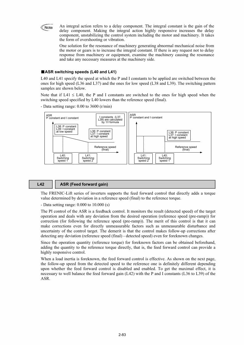
2-83
An integral action refers to a delay component. The integral constant is the gain of the delay component. Making the integral action highly responsive increases the delay component, unstabilizing the control system including the motor and machinery. It takes the form of overshooting or vibration. One solution for the resonance of machinery generating abnormal mechanical noise from the motor or gears is to increase the integral constant. If there is any request not to delay response from machinery or equipment, examine the machinery causing the resonance and take any necessary measures at the machinery side.
ASR switching speeds (L40 and L41) L40 and L41 specify the speed at which the P and I constants to be applied are switched between the ones for high speed (L36 and L37) and the ones for low speed (L38 and L39). The switching pattern samples are shown below. Note that if L41 ≤ L40, the P and I constants are switched to the ones for high speed when the switching speed specified by L40 lowers than the reference speed (final). - Data setting range: 0.00 to 3600 (r/min)
ASRP constant and I constant
L38: P constantL39: I constantat low speed L36: P constant
L37: I constantat high speed
Reference speed(final)
I constants (L37,L39) are calculated
by 1/I formula
L41:Switchingspeed 2
L40:Switchingspeed 1
L40:Switchingspeed 1
L41:Switchingspeed 2
Reference speed(final)
L36: P constantL37: I constantat high speed
ASRP constant and I constant
L42 ASR (Feed forward gain) The FRENIC-Lift series of inverters supports the feed forward control that directly adds a torque value determined by deviation in a reference speed (final) to the reference torque. - Data setting range: 0.000 to 10.000 (s) The PI control of the ASR is a feedback control. It monitors the result (detected speed) of the target operation and deals with any deviation from the desired operation (reference speed (pre-ramp)) for correction (for following the reference speed (pre-ramp)). The merit of this control is that it can make corrections even for directly unmeasurable factors such as unmeasurable disturbance and uncertainty of the control target. The demerit is that the control makes follow-up corrections after detecting any deviation (reference speed (final) - detected speed) even for foreknown changes. Since the operation quantity (reference torque) for foreknown factors can be obtained beforehand, adding the quantity to the reference torque directly, that is, the feed forward control can provide a highly responsive control. When a load inertia is foreknown, the feed forward control is effective. As shown on the next page, the follow-up speed from the detected speed to the reference one is definitely different depending upon whether the feed forward control is disabled and enabled. To get the maximal effect, it is necessary to well balance the feed forward gain (L42) with the P and I constants (L36 to L39) of the ASR.

2-84
Reference speed (final)
Detected speedDetected speed
TorquecommandTorque
command
0
0
0
0
Speed
Torque output
Speed
Torque outputTime
FF control disabled(only PI feedback control enabled)
FF control enabled(PI feedback control enabled together)
Reference speed (final)
TimeTime
Time
The effect above can be obtained also by adjusting the P and I constants to speed up the response, but it involves any demerits such as resonance of machinery and vibration noise.
L49 Vibration Suppression Observer (Gain) L50 Vibration Suppression Observer (Integral time) L51 Vibration Suppression Observer (Load inertia)
L49 through L51 specify the mechanical inertia for the vibration suppression observer. The observer runs the simulation model inside the inverter, estimates a load torque (that can be a vibration element), and applies it to the reference torque for canceling the load torque. This way the observer quickly attenuates the vibration caused by resonance of machinery. Gain (L49) L49 specifies the compensation gain for the vibration suppression observer. Specification of 0.00 disables the observer. Usually set the gain within the range from 0.00 to 0.50. - Data setting range: 0.00 (Disable) 0.01 to 1.00 Integral time (L50) L50 specifies the integral time of the observer. No change is required except special cases. - Data setting range: 0.005 to 1.000 (s) Load inertia (L51) L51 specifies the moment of inertia of the load. After converting the moment of inertia of the motor and traction machine for the motor shaft, use the value. - Data setting range: 0.01 to 655.35 (kgm2)
L52 Start Control Mode F23 (Starting Speed)
L52 specifies the start control mode.
Data for L52 Function
0 Enable speed start mode.
1 Enable torque start mode.
For details, refer to the description of F23.
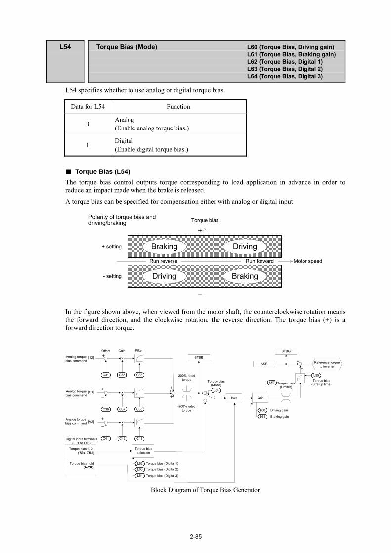
2-85
L54 Torque Bias (Mode) L60 (Torque Bias, Driving gain)
L61 (Torque Bias, Braking gain) L62 (Torque Bias, Digital 1) L63 (Torque Bias, Digital 2) L64 (Torque Bias, Digital 3)
L54 specifies whether to use analog or digital torque bias.
Data for L54 Function
0 Analog (Enable analog torque bias.)
1 Digital (Enable digital torque bias.)
Torque Bias (L54) The torque bias control outputs torque corresponding to load application in advance in order to reduce an impact made when the brake is released. A torque bias can be specified for compensation either with analog or digital input
Run forward Motor speedRun reverse
Driving
Driving
Braking
Braking
Torque bias
+ setting
- setting
+
-
Polarity of torque bias anddriving/braking
In the figure shown above, when viewed from the motor shaft, the counterclockwise rotation means the forward direction, and the clockwise rotation, the reverse direction. The torque bias (+) is a forward direction torque.
[12]
Gain
Driving gain
Braking gain
L60
L61
×
C32
[C1] ×
C37
[V2] ×
C42
Gain
Torque bias 1, 2(TB1, TB2)
Torque biasselection
Torque bias (Digital 1)
Torque bias (Digital 2)
Torque bias (Digital 3)
Torque bias hold(H-TB)
Hold
L62
L63
L64
++
+
Torque bias(Mode)
L54
Reference torqueto inverter
+
-
C36
+
-
C41
+
-
Offset
C31
C43
C33
C38
Filter
Analog torquebias command
Analog torquebias command
Analog torquebias command
200% ratedtorque
Digital input terminals(E01 to E08)
BTBB
ASR+
+
BTBG
Torque bias(Stratup time)
L55
L57 Torque bias(Limiter)
-200% ratedtorque
Block Diagram of Torque Bias Generator

2-86
Analog torque bias (L54 = 0)
Setting L54 data to "0" enables torque bias setting with analog input. When L54 = 0, assigning a reference torque bias to terminals [12] and [V2] (by function codes E61 and E63) inputs a torque bias with analog voltage input, and assigning it to terminal [C1] (by E62), a torque bias with analog current input. If no reference torque bias is assigned to any of terminals [12], [V2], and [C1], however, the analog torque bias is 0 (%). Terminal commands TB1 and TB2 assigned to the general-purpose, programmable input terminals (by function codes E01 to E08, E98 and E99) are ignored. When an analog torque bias is specified, adjust the gain with L60 (Driving gain) and L61 (Braking gain). If L60 (L61) = 100%, analog input voltage -10 to +10 VDC corresponds to -100 to +100% of the motor rated torque and analog input current 4 to 20 mA corresponds to 0 to 100% of the motor rated torque, assuming that gain = 100% and offset = 0%.
- Balancing With the elevator being loaded with a counterweight, adjust a torque bias amount to 0% relative to the input voltage of the load sensor. This adjustment should be made when the elevator is stationary with a counterweight loaded and the brake being on. Setting E43 data (LED monitor) to "19" monitors the torque bias balance adjustment value (BTBB) on the LED monitor. For the multi-function keypad with ROM version 8510, press the key in Running mode and switch to monitor page 14. Adjust the balance by adjusting analog input with C31 ([12] Offset), C36 ([C1] Offset) or C41 ([V2] Offset) so that the monitored data comes to 0 (%). (The monitored data shows the ratio to the motor rating torque in percentages.)
- Gain adjustment (1) The gain adjustment should follow the balance adjustment. Before proceeding to the gain
adjustment, set analog input with C32 ([12] Gain), C37 ([C1] Gain), or C42 ([V2] Gain) to 100 (%).
(2) According to the table below, determine the initial values of the gains at the driving and braking sides (L60 and L61).
Function codes to be set with no load
Motor rotational direction when the
elevator lifts up
When the load increases, the analog voltage/current input (load sensor)
will:
Initial values of L60 and L61
data UP DOWN
Increase +100 (%) Forward
Decrease -100 (%) L61 L60
Increase -100 (%) Reverse
Decrease +100 (%) L60 L61
(3) Setting E43 data (LED monitor) to "20" monitors the torque bias gain adjustment value (BTBG)
on the LED monitor. For the multi-function keypad with ROM version 8510, press the key in Running mode and switch to monitor page 15.
(4) With no load, run the elevator up at a speed of 2 to 10% of the elevator rated speed. Adjust L61 and L60 data in the forward and reverse direction, respectively, so that the monitored data comes to approximately 0 (%) when the speed is stabilized. (The monitored data shows the ratio to the motor rating torque in percentages.)
(5) With no load, run the elevator down at a speed of 2 to 10% of the elevator rated speed. Adjust L60 and L61 data in the forward and reverse direction, respectively, so that the monitored data comes to approximately 0 (%) when the speed is stabilized.
For torque bias setting with current input, the input current on terminal [C1] should be within the range from 4 to 20 mA when the elevator is with no load to the maximum load. The input current from 0 to 4 mA is regarded as 0. If the current input of 4 mA or below is not avoidable, change the load (the maximum load, for example) and perform steps (4) and (5) above when the current input on [C1] is kept within the range from 4 to 20 mA.
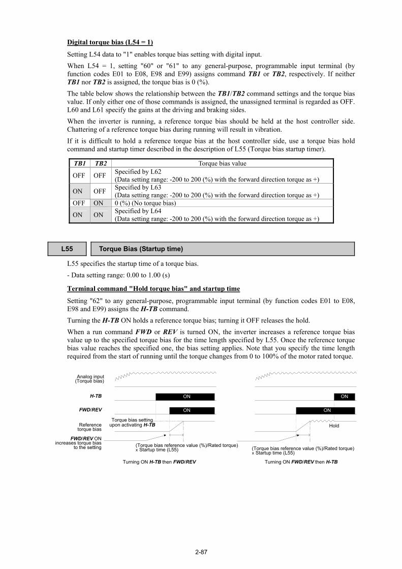
2-87
Digital torque bias (L54 = 1)
Setting L54 data to "1" enables torque bias setting with digital input. When L54 = 1, setting "60" or "61" to any general-purpose, programmable input terminal (by function codes E01 to E08, E98 and E99) assigns command TB1 or TB2, respectively. If neither TB1 nor TB2 is assigned, the torque bias is 0 (%). The table below shows the relationship between the TB1/TB2 command settings and the torque bias value. If only either one of those commands is assigned, the unassigned terminal is regarded as OFF. L60 and L61 specify the gains at the driving and braking sides. When the inverter is running, a reference torque bias should be held at the host controller side. Chattering of a reference torque bias during running will result in vibration. If it is difficult to hold a reference torque bias at the host controller side, use a torque bias hold command and startup timer described in the description of L55 (Torque bias startup timer).
TB1 TB2 Torque bias value
OFF OFF Specified by L62 (Data setting range: -200 to 200 (%) with the forward direction torque as +)
ON OFF Specified by L63 (Data setting range: -200 to 200 (%) with the forward direction torque as +)
OFF ON 0 (%) (No torque bias)
ON ON Specified by L64 (Data setting range: -200 to 200 (%) with the forward direction torque as +)
L55 Torque Bias (Startup time) L55 specifies the startup time of a torque bias. - Data setting range: 0.00 to 1.00 (s)
Terminal command "Hold torque bias" and startup time
Setting "62" to any general-purpose, programmable input terminal (by function codes E01 to E08, E98 and E99) assigns the H-TB command. Turning the H-TB ON holds a reference torque bias; turning it OFF releases the hold. When a run command FWD or REV is turned ON, the inverter increases a reference torque bias value up to the specified torque bias for the time length specified by L55. Once the reference torque bias value reaches the specified one, the bias setting applies. Note that you specify the time length required from the start of running until the torque changes from 0 to 100% of the motor rated torque.
ON
ON
Hold
(Torque bias reference value (%)/Rated torque)x Startup time (L55)
Turning ON FWD/REV then H-TB
H-TB
FWD/REV
Analog input(Torque bias)
Referencetorque bias
FWD/REV ONincreases torque bias
to the setting
ON
ON
Turning ON H-TB then FWD/REV
Torque bias settingupon activating H-TB
(Torque bias reference value (%)/Rated torque)x Startup time (L55)

2-88
L56 Torque Bias (Reference torque end time)
L66 (Unbalanced Load Compensation, Activation time) L67 (Unbalanced Load Compensation, Holding time)
L56 sets up the reference torque end timer whose functional property differs whether in speed control or in torque control. - Data setting range: 0.00 (Disable) 0.01 to 20.00 (s) In speed control
During the shutdown sequence in speed control, the inverter decreases a reference torque value held internally to 0, taking time specified by L56 for deceleration. Note that you set the time length required to decrease the motor rating torque from 100 to 0% to the reference torque end timer.
Time0
FWD
Creep speedcommand
Zero speedcommand
Torque bias
Reference torque ofinverter inside
L56 slope to decelerate
SS1
SS2
Creep speed
SS4
Inverter outputshut downcommand
Inverter outputshut down
Stop speedStop speed duration
Reference Torque End Sequence in Speed Control
In torque control
During the startup sequence in torque control, the inverter decreases the torque bias amount (Torque bias amount issued from the user controller + Unbalanced load compensation) to 0 using the time constant specified by L56. It is triggered after the time length specified by L67 (Holding time) from when the command UNBL is turned ON (if the UNBL command is assigned to any general-purpose, programmable input terminal by setting "67") or when a run command is turned ON (if no UNBL is assigned). The activation timer setting (L66) should be less than the holding time (L67). If L66 > L67, the L66 setting automatically applies to the L67 setting inside the inverter.
Time
Speed
0
ONFWD
Torque bias
L67
Decelerated by L56 timeconstant
Startup timer slopeactivated by L55
Reference Torque End Sequence in Torque Control

2-89
L57 Torque Bias (Limiter)
L57 specifies the absolute value of a torque bias amount to be used after the driving or braking gain is applied, as a percentage to the rated torque. It limits a torque bias amount for protection against a load sensor defective and others. - Data setting range: 0 to 200 (%)
L60 Torque Bias (Driving gain) L54 (Torque Bias, Mode)
L61 Torque Bias (Braking gain) L54 (Torque Bias, Mode)
L60 and L61 specify the gains of torque biases at the driving and braking sides, respectively, as a percentage to the rated torque. - Data setting range: -1000.0 to 1000.0 (%)
Refer to the description of function code L54 for details.
L62 Torque Bias (Digital 1) L54 (Torque Bias, Mode)
L63 Torque Bias (Digital 2) L54 (Torque Bias, Mode)
L64 Torque Bias (Digital 3) L54 (Torque Bias, Mode)
L62 to L64 specify digital torque bias amounts with the forward rotation direction torque as a positive value. - Data setting range: -200 to 200 (%)
Refer to the description of function code L54 for details.

2-90
L65 Unbalanced Load Compensation (Operation)
L65 specifies whether to enable or disable the unbalanced load compensation.
Data for L65 Function
0 Disable the unbalanced load compensation.
1 Enable the unbalanced load compensation. Unbalanced load compensation
This compensation function estimates an unbalanced load and calculates the required torque bias amount inside the inverter. Setting "67" to any general-purpose, programmable input terminal (by function codes E01 to E08, E98 and E99) assigns the UNBL command. With the UNBL being assigned, entering a UNBL command following a run command starts estimating an unbalanced load. If no UNBL is assigned, entering a run command starts it. Just as the torque bias function, this compensation function lightens an impact made when the brake is released even in elevator systems having no load sensors. The table below lists function codes to be used in unbalanced load compensation.
Function code Name Setting required
E01 to E08, E98, and E99
Command assignment to terminals [X1] to [X8] Setting "67" assigns UNBL.
Turn the UNBL ON to start estimating an unbalanced load (and start L66 and L67 timers). If no UNBL is assigned, turn a run command ON to start estimating an unbalanced load.
L66 Unbalanced load compensation (Activation timer)
Specify the maximum time length for estimating an unbalanced load.
L67 *1 Unbalanced load compensation (Holding time)
Specify the start time for decreasing the torque bias amount in torque control. L66 < L67
L68 Unbalanced load compensation (ASR P constant)
Specify the ASR P constant to use in unbalanced load calculation. If vibration occurs, decrease the constant.
L69 Unbalanced load compensation (ASR I constant)
Specify the ASR I constant to use in unbalanced load calculation. If vibration occurs, increase the constant.
*1 Required only in torque control.
When an UNBL command is assigned to any general-purpose, programmable input terminal, be sure to enter a run command before entry of an UNBL command. Entry of an UNBL preceding a run command does not perform unbalanced load compensation.

2-91
In speed control
Unbalanced load compensation requires keeping the reference speed (pre-ramp) at 0.00 r/min and releasing the brake during the period from the start of running to the completion of calculation (that is, during the activation timer setting specified by L66). If the reference speed (pre-ramp) other than 0.00 r/min is entered before the time length specified by L66 elapses, unbalanced load compensation immediately starts. During the time length (L66) from the start of estimation of an unbalanced load, the inverter holds zero speed with the zero speed control specified when unbalanced load compensation is enabled. After the time length (L66), the current reference torque value inside the inverter will be taken as a torque bias amount. After that, the inverter runs in speed control with the torque bias amount under ASR.
Time
Speed
0
ONFWD
ON
ON
Zero speedcommand
High speedcommand
Creep speedcommand
Zero speedcommand
ReleaseBrake Charge
Torque bias
τ4
Torque commandinside the inverter
L57
SS1
SS2
High speed
Creep speed
UNBLON
ONSS4
L66L55
τ1
τ3
τ2
Details (1) During the period from the entry of a run command to that of an UNBL command, the inverter
runs with "User controller's torque bias amount τ2." (2) During the time length (L66) from the start of estimation of an unbalanced load, the "Inverter
internal reference torque" is equal to "Reference torque at the zero speed hold period in inverter position deviation zero control" plus "User controller's torque bias amount τ2." Finally, the "Inverter internal reference torque" becomes equal to "Load torque τ1."
(3) When the time length (L66) elapses after the start of estimation of an unbalanced load, adding the "Unbalanced load compensation amount τ3" to "User controller's torque bias amount τ2" produces "Torque bias amount τ4." At that point, τ3 = τ1 - τ2. After that, the inverter runs in speed control with the "Torque bias amount τ4" and under normal ASR operation.
(4) During the inverter shutdown sequence, the inverter decreases a reference torque value held in itself to 0, taking time specified by L56, and then shuts itself down.
1 2 3 4

2-92
In torque control
The inverter adds "Unbalanced load compensation amount" to "User controller's reference torque." The added compensation amount starts decreasing in accordance with the reference torque end time (L56) after the holding time (L67) elapses from the start of unbalanced load compensation calculation.
L66 Unbalanced load compensation (Activation time)
L56 (Torque Bias, Reference torque end time) L65 (Unbalanced Load Compensation, Operation)
L66 specifies the calculation time of unbalanced load compensation amount to apply after the UNBL command is turned ON.
- Data setting range: 0.01 to 2.00 (s)
Refer to the descriptions of function codes L56 and L65 for details.
L67 Unbalanced load compensation (Holding time) L56 (Torque Bias, Reference torque end time) L65 (Unbalanced Load Compensation, Operation)
L67 specifies the starting time for decreasing the torque bias amount in torque control.
- Data setting range: 0.01 to 20.00 (s)
Refer to the descriptions of function codes L56 and L65 for details.
L68 Unbalanced load compensation (ASR P constant)
L68 specifies the ASR P constant to use in unbalanced load calculation.
Set a larger constant than the one specified in normal operation. If vibration occurs, decrease it.
- Data setting range: 0.00 to 200.00
L69 Unbalanced load compensation (ASR I constant)
L69 specifies the ASR I constant to use in unbalanced load calculation.
Set a smaller constant than the one specified in normal operation. If vibration occurs, increase it.
- Data setting range: 0.001 to 1.000 (s)
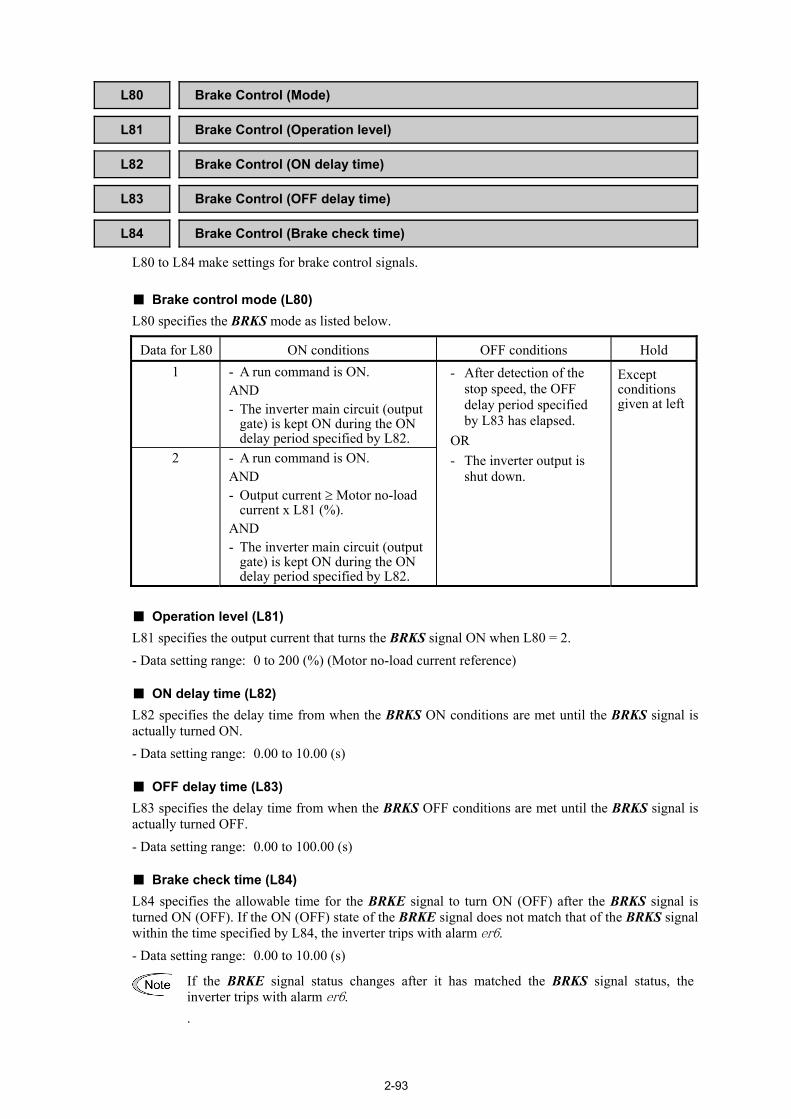
2-93
L80 Brake Control (Mode) L81 Brake Control (Operation level) L82 Brake Control (ON delay time) L83 Brake Control (OFF delay time) L84 Brake Control (Brake check time)
L80 to L84 make settings for brake control signals. Brake control mode (L80) L80 specifies the BRKS mode as listed below.
Data for L80 ON conditions OFF conditions Hold 1 - A run command is ON.
AND - The inverter main circuit (output
gate) is kept ON during the ON delay period specified by L82.
2 - A run command is ON. AND - Output current ≥ Motor no-load
current x L81 (%). AND - The inverter main circuit (output
gate) is kept ON during the ON delay period specified by L82.
- After detection of the stop speed, the OFF delay period specified by L83 has elapsed.
OR - The inverter output is
shut down.
Except conditions given at left
Operation level (L81) L81 specifies the output current that turns the BRKS signal ON when L80 = 2. - Data setting range: 0 to 200 (%) (Motor no-load current reference) ON delay time (L82) L82 specifies the delay time from when the BRKS ON conditions are met until the BRKS signal is actually turned ON. - Data setting range: 0.00 to 10.00 (s) OFF delay time (L83) L83 specifies the delay time from when the BRKS OFF conditions are met until the BRKS signal is actually turned OFF. - Data setting range: 0.00 to 100.00 (s) Brake check time (L84) L84 specifies the allowable time for the BRKE signal to turn ON (OFF) after the BRKS signal is turned ON (OFF). If the ON (OFF) state of the BRKE signal does not match that of the BRKS signal within the time specified by L84, the inverter trips with alarm er6. - Data setting range: 0.00 to 10.00 (s)
If the BRKE signal status changes after it has matched the BRKS signal status, the inverter trips with alarm er6. .

2-94
Brake control signal BRKS
Setting "57" to any of the general-purpose, programmable output terminal (by E20 to E24 and E27) assigns a BRKS signal to that terminal. The BRKS signal is available in two modes specified by L80. The BRKS signal turns OFF when the time length specified by L83 elapses after the speed (≥ stop speed) drops below the stop speed, independent of a run command. Adjust the braking timing to match the running pattern. If the BRKS signal turns OFF with a run command being ON, the BRKS signal will no longer turn ON again even the ON conditions are met again. To turn the BRKS signal ON again, turn the run command OFF once. Brake confirmation signal BRKE
Setting "65" to any of the general-purpose, programmable input terminal (by E01 to E08, E98 and E99) assigns a BRKE signal to that terminal. This signal is used to confirm whether the actual brake works normally with the BRKS signal issued from the inverter. Configure an external circuit that turns the signal ON or OFF when the brake is actually released or applied, respectively. If the output status of the BRKS signal is not identical with the input status of the BRKE signal, the inverter trips with alarm er6. If there is a time lag between the status change of the BRKS signal and the entry of the BRKE signal, specify the lag time with L84 (Brake check timer). During the lag time after the BRKS signal status changes, the discrepancy between the output status of the BRKS signal and input status of the BRKE signal does not trigger a trip. Note that the time lag function does not work unless BRKS or BRKE is specified. Make sure that the total time of the brake check time (L84) and the OFF delay time (L83) is less than the stop speed holding time (H67).
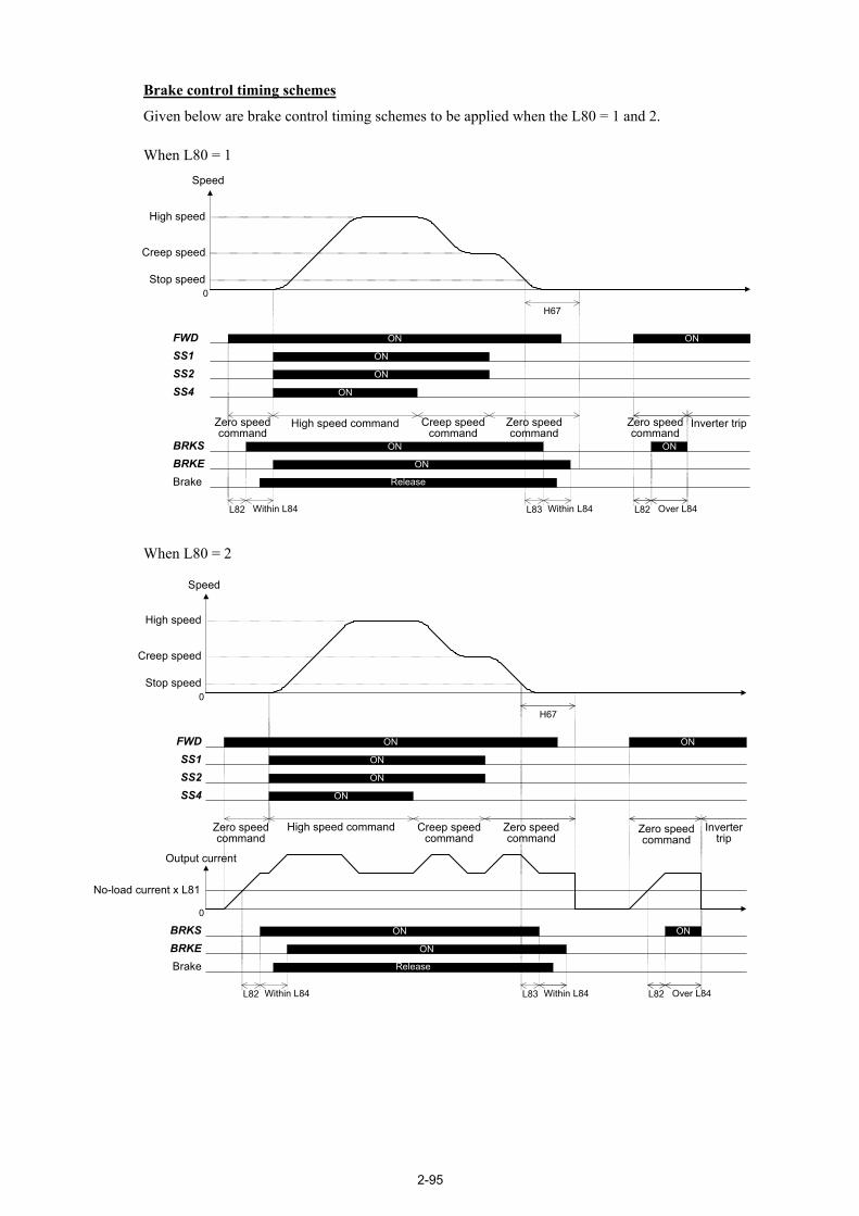
2-95
Brake control timing schemes
Given below are brake control timing schemes to be applied when the L80 = 1 and 2. When L80 = 1
Speed
0
High speed
Creep speed
FWDSS1SS2SS4
ON
ON
ON
ON
Zero speedcommand
High speed command Creep speedcommand
Zero speedcommand
BRKEBrake Release
ON
BRKS ONON
Stop speed
Zero speedcommand
Inverter trip
ON
H67
L82 Over L84L82 Within L84 L83 Within L84
When L80 = 2
Speed
0
High speed
Creep speed
FWDSS1SS2SS4
ON
ON
ON
ON
Zero speedcommand
High speed command Creep speedcommand
Zero speedcommand
BRKEBrake Release
ON
BRKS ONON
Stop speed
Zero speedcommand
Invertertrip
ON
H67
L82L82 Within L84 L83 Within L84
Output current
No-load current x L81
0
Over L84

2-96
L85 MC Control (Startup delay time) L86 MC Control (MC OFF delay time)
L85 and L86 specify the ON and OFF timings of the MC control signal SW52-2 that is assigned to a general-purpose, programmable output terminal by setting "12" with E20 to E24 and E27. The MC control signal opens or closes the magnetic contactor connected between the inverter and motor. Startup delay time (L85) L85 specifies the delay time from when the MC control signal SW52-2 turns ON until the main circuit output gate turns ON. - Data setting range: 0.00 to 10.00 (s)
Even if no SW52-2 is assigned to a general-purpose programmable output terminal, turning a run command ON turns the main circuit output gate ON after the delay time specified by L85 elapses.
MC OFF delay time (L86) L86 specifies the delay time from when the main circuit output gate turns OFF until the MC control signal SW52-2 turns OFF. - Data setting range: 0.00 to 10.00 (s)
MC control
The table below lists the inverter running conditions and triggers required for turning the MC control signal ON or OFF. The timing scheme is shown on the next page.
SW52-2 ON SW52-2 OFF Current status retained
(1) When all of the following conditions are met, turning a run command from OFF to ON turns the MC control signal ON.
- "Coast-to-stop" BX OFF - No trip - Terminal [EN] ON - "Force to decelerate" DRS OFF
(2) Any of the following events with a run command being ON turns the MC control signal ON.
- "Coast-to-stop" BX from ON to OFF.- A trip that occurred is reset. - Terminal [EN] from OFF to ON
Any of the following events with the MC control signal being ON turns the MC control signal OFF after the MC OFF delay time specified by L86. - Inverter main circuit output gate
from ON to OFF - Run command from ON to OFF with
the inverter main circuit output gate being OFF
- "Coast-to-stop" BX from OFF to ON - A trip occurs. - Terminal [EN] from ON to OFF - "Force to decelerate" DRS from OFF
to ON (below the stop speed).
Except the conditions listed at left
* When the conflicting conditions are present, e.g., from ON to OFF conditions and from OFF to ON conditions, the latter event has priority.
* The BX and [EN] are in normal logic. * The "Force to decelerate" state is kept from the entry of a DRS command until the DRS is turned
ON, and the run command and inverter main circuit output gate are turned OFF.

2-97
Speed
0
Run commandSW52-2
Inverter main circuit(output gate)
ON
ON
ON
L85: MC control(Startup delay time)
H67: Stop speed(Holding time)
Stop speed
L86: MC control(MC OFF delay time)
MC Control Signal Timing Scheme

2-98
L87 Door Control (Door open starting speed) L88 Door Control (Door open delay time) L89 Door Control (Door open period)
L87 to L89 specify the door open parameters relating to the door control signal DOPEN that is assigned to a general-purpose, programmable output terminal by setting "78" with E20 to E24 and E27. Door open starting speed (L87) L87 specifies the reference speed (final) at which the door control signal DOPEN is turned ON. The DOPEN is turned ON actually after the door open delay time specified by L88. - Data setting range: 0.00 to 3600 (r/min) Door open delay time (L88) L88 specifies the delay time from when the speed drops below the door open starting speed (L87) until the DOPEN signal is turned ON. - Data setting range: 0.0 to 10.0 (s) Door open period (L89) L89 specifies the period during which the DOPEN is kept ON. - Data setting range: 0.1 to 30.0 (s) Door control
When the reference speed (final) drops below the door open starting speed (L87) during deceleration and the door open delay time (L88) elapses, the DOPEN is turned ON and kept ON during the door open period (L89).
Time
Speed
L88:Door control(Door opendelay time)
L89:Door control(Door openperiod)
Digital outputDOPEN ON
L87:Door control(Door openstarting speed)
OFF
Increasing the reference speed (final) above the speed (L87) with the DOPEN being OFF activates the DOPEN ON process judgment. If the reference speed (final) does not exceed the speed (L87), the L88 and L89 specifications will be ignored so that the DOPEN will be kept OFF. Decreasing the reference speed (final) from the speed exceeding the L87 down to less than the L87 activates the delay timer (L88). After the delay time (L88) elapses, the DOPEN turns ON during the door open period (L89). This door control applies to also the battery operation. When the battery operation speed does not reach the door open starting speed (L87), the DOPEN will be kept OFF. Note: When the L87 = 0.00, the DOPEN does not work.
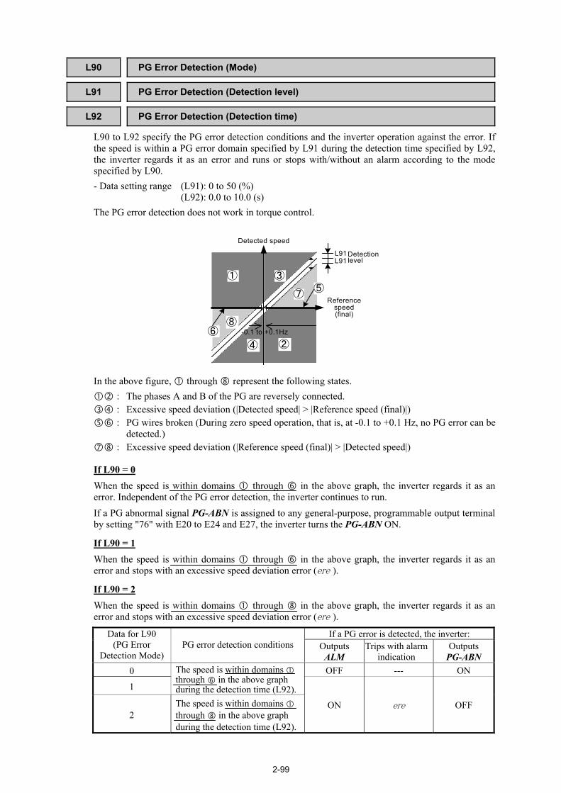
2-99
L90 PG Error Detection (Mode) L91 PG Error Detection (Detection level) L92 PG Error Detection (Detection time)
L90 to L92 specify the PG error detection conditions and the inverter operation against the error. If the speed is within a PG error domain specified by L91 during the detection time specified by L92, the inverter regards it as an error and runs or stops with/without an alarm according to the mode specified by L90. - Data setting range (L91): 0 to 50 (%) (L92): 0.0 to 10.0 (s) The PG error detection does not work in torque control.
Referencespeed(final)
Detected speed
Detectionlevel
③
②
①
④
⑦
⑧
⑤
⑥ -0.1 to +0.1Hz
L91L91
In the above figure, through represent the following states.
: The phases A and B of the PG are reversely connected. : Excessive speed deviation (|Detected speed| > |Reference speed (final)|) : PG wires broken (During zero speed operation, that is, at -0.1 to +0.1 Hz, no PG error can be
detected.) : Excessive speed deviation (|Reference speed (final)| > |Detected speed|)
If L90 = 0 When the speed is within domains through in the above graph, the inverter regards it as an error. Independent of the PG error detection, the inverter continues to run. If a PG abnormal signal PG-ABN is assigned to any general-purpose, programmable output terminal by setting "76" with E20 to E24 and E27, the inverter turns the PG-ABN ON.
If L90 = 1 When the speed is within domains through in the above graph, the inverter regards it as an error and stops with an excessive speed deviation error (ere ).
If L90 = 2 When the speed is within domains through in the above graph, the inverter regards it as an error and stops with an excessive speed deviation error (ere ).
If a PG error is detected, the inverter: Data for L90 (PG Error
Detection Mode) PG error detection conditions Outputs
ALM Trips with alarm
indication Outputs
PG-ABN 0 OFF --- ON
1
The speed is within domains through in the above graph during the detection time (L92).
2 The speed is within domains through in the above graph during the detection time (L92).
ON ere OFF

2-100
L93 Overheat Early Warning Level
When the temperature reaches the overheat early warning level that is n°C below the trip level, the inverter issues an overheat early warning signal. L93 specifies the n°C. The early warning signal OH is assigned to a general-purpose, programmable output terminal by setting "28" with E20 to E24 and E27. - Data setting range: 1 to 20 (deg)
ON conditions OFF conditions Current status retained
When any of the following conditions is met, the OH signal is turned ON.
- The heat sink temperature is higher than "Heat sink overheat trip temperature - L93 setting."
- The inverter inside temperature is higher than "Internal overheat trip temperature - L93 setting."
- The IGBT junction temperature is higher than "Inverter overload trip temperature - L93 setting."
When all of the following conditions are met, the OH signal is turned OFF.
- The heat sink temperature is lower than "Heat sink overheat trip temperature - L93 setting - 3°C."
- The inverter inside temperature is lower than "Internal overheat trip temperature - L93 setting - 3°C."
- The IGBT junction temperature is lower than "Inverter overload trip temperature - L93 setting - 3°C."
Except the conditions listed at left
Trip level
Early warning OFF level
L93 setting
3
OH ON OFFOFF
Early warning ON level