DESIGN & TECHNICAL MANUAL - F.G. EUROPE · design & technical manual indoor asyg07llce asyg09llce...
44
AIR CONDITIONER Wall mounted type DESIGN & TECHNICAL MANUAL INDOOR ASYG07LLCE ASYG09LLCE ASYG12LLCE OUTDOOR AOYG07LLCE AOYG09LLCE AOYG12LLCE DR_AS036EF_02 2016.04.06
Transcript of DESIGN & TECHNICAL MANUAL - F.G. EUROPE · design & technical manual indoor asyg07llce asyg09llce...

AIR CONDITIONER
Wall mounted type
DESIGN & TECHNICAL MANUAL
INDOORASYG07LLCEASYG09LLCEASYG12LLCE
OUTDOOR
AOYG07LLCEAOYG09LLCEAOYG12LLCE
DR_AS036EF_022016.04.06

Notices:• Product specifications and design are subject to change without notice for future improvement.• For further details, please check with our authorized dealer.
Copyright © 2016, 2017 Fujitsu General Limited. All rights reserved.
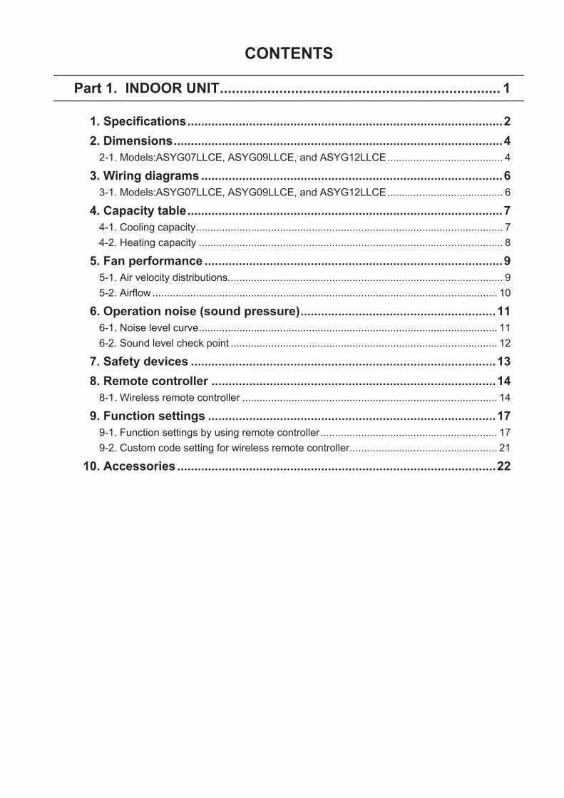
CONTENTS
Part 1. INDOOR UNIT....................................................................... 1
1. Specifications............................................................................................2 2. Dimensions................................................................................................4
2-1. Models:ASYG07LLCE, ASYG09LLCE, and ASYG12LLCE........................................ 4
3. Wiring diagrams ........................................................................................63-1. Models:ASYG07LLCE, ASYG09LLCE, and ASYG12LLCE........................................ 6
4. Capacity table............................................................................................74-1. Cooling capacity.......................................................................................................... 74-2. Heating capacity ......................................................................................................... 8
5. Fan performance .......................................................................................95-1. Air velocity distributions............................................................................................... 95-2. Airflow ....................................................................................................................... 10
6. Operation noise (sound pressure).........................................................116-1. Noise level curve....................................................................................................... 116-2. Sound level check point ............................................................................................ 12
7. Safety devices .........................................................................................13 8. Remote controller ...................................................................................14
8-1. Wireless remote controller ........................................................................................ 14
9. Function settings ....................................................................................179-1. Function settings by using remote controller............................................................. 179-2. Custom code setting for wireless remote controller................................................... 21
10. Accessories .............................................................................................22

Part 2. OUTDOOR UNIT................................................................. 23
1. Specifications..........................................................................................24 2. Dimensions..............................................................................................25
2-1. Models:AOYG07LLCE, AOYG09LLCE, and AOYG12LLCE..................................... 25
3. Installation space ....................................................................................263-1. Models:AOYG07LLCE, AOYG09LLCE, and AOYG12LLCE..................................... 26
4. Refrigerant circuit ...................................................................................294-1. Models:AOYG07LLCE, AOYG09LLCE, and AOYG12LLCE..................................... 29
5. Wiring diagrams ......................................................................................305-1. Models:AOYG07LLCE, AOYG09LLCE, and AOYG12LLCE..................................... 30
6. Capacity compensation rate for pipe length and height difference....316-1. Models:AOYG07LLCE and AOYG09LLCE............................................................... 316-2. Model:AOYG12LLCE................................................................................................ 32
7. Additional charge calculation ................................................................337-1. Models:AOYG07LLCE and AOYG09LLCE............................................................... 337-2. Model:AOYG12LLCE................................................................................................ 33
8. Airflow......................................................................................................348-1. Models:AOYG07LLCE and AOYG09LLCE............................................................... 348-2. Model:AOYG12LLCE................................................................................................ 34
9. Operation noise (sound pressure).........................................................359-1. Noise level curve....................................................................................................... 359-2. Sound level check point ............................................................................................ 37
10. Electrical characteristics ........................................................................3811. Safety devices .........................................................................................3912. Accessories .............................................................................................40
CONTENTS (continued)

Part 1. INDOOR UNITWALL MOUNTED TYPE:
ASYG07LLCEASYG09LLCEASYG12LLCE

1. SpecificationsType
Wall mounted
Inverter heat pump
Model name ASYG07LLCE ASYG09LLCE ASYG12LLCEPower supply 230 V ~ 50 HzAvailable voltage range 198—264 V
Capacity
CoolingRated
kW 2.00 2.50 3.40Btu/h 6,800 8,500 11,600
Min.—Max.kW 0.9—2.8 0.9—3.0 0.9—3.8
Btu/h 3,100—9,500 3,100—10,200 3,100—13,000
HeatingRated
kW 2.70 3.00 4.00Btu/h 9,200 10,200 13,600
Min.—Max.kW 0.9—3.6 0.9—3.8 0.9—5.0
Btu/h 3,100—12,200 3,100—13,000 3,100—17,000
Input power
CoolingRated
kW
0.470 0.730 1.080Min.—Max. 0.25—1.29 0.25—1.29 0.25—1.40
HeatingRated 0.620 0.740 1.130Min.—Max. 0.25—1.63 0.25—1.63 0.25—1.98
Fan
HIGH
W
29MED 19LOW 8QUIET 5
CurrentCooling
Rated A2.6 3.5 5.2
Heating 3.0 3.5 5.4EER Cooling
kW/kW4.26 3.42 3.15
COP Heating 4.35 4.05 3.54Sensible capacity Cooling kW 1.30 1.60 2.20
Power factorCooling
%79 91 91
Heating 90 92 92Moisture removal L/h (pints/h) 1.0 (1.8) 1.3 (2.3) 1.8 (3.2)
Maximum operating current *1Cooling
A6.0 6.0 6.5
Heating 7.5 7.5 9.0
FanAirflow rate
Cooling
HIGH
m3/h
720MED 600LOW 420QUIET 325
Heating
HIGH 740MED 600LOW 450QUIET 325
Type × Q'ty Cross flow fan × 1Motor output W 30
Sound pressure level *2
Cooling
HIGH
dB (A)
43MED 38LOW 33QUIET 22
Heating
HIGH 43MED 38LOW 33QUIET 22
Heat exchanger type
Dimensions (H × W × D)mm
256 × 630 × 20Fin pitch 1.1Rows × Stages 2 × 16Pipe type Copper tubeFin type Aluminum
EnclosureMaterial Polystyrene
ColorWhite + Pearl white (painted)
Approximate color of Munsell N 9.25/Dimensions(H × W × D)
Netmm
262 × 820 × 206Gross 263 × 870 × 328
WeightNet
kg7.0
Gross 9.5
Connection pipeSize
Liquidmm (in)
Ø 6.35 (Ø 1/4)Gas Ø 9.52 (Ø 3/8)
Method Flare
Drain hoseMaterial PP+LLDPESize mm Ø 13.8 (I.D.), Ø 15.8 to Ø 16.7 (O.D.)
Operation rangeCooling
°C 18 to 32%RH 80 or less
Heating °C 16 to 30Remote controller type Wireless
NOTES:• Specifications are based on the following conditions:
– Cooling: Indoor temperature of 27 °CDB/19 °CWB, and outdoor temperature of 35 °CDB/24 °CWB.– Heating: Indoor temperature of 20 °CDB/15 °CWB, and outdoor temperature of 7 °CDB/6 °CWB.– Pipe length: 5 m, Height difference: 0 m. (Between outdoor unit and indoor unit.)
• Protective function might work when using it outside the operation range.• *1: Maximum current is maximum value when operated within the operation range.• *2: Sound pressure level:
– Measured values in manufacturer’s anechoic chamber.– Because of the surrounding sound environment, the sound levels measured in actual installation conditions might be higher than the specified values here.
DESIGN & TECHNICAL MANUAL
- 2 -
WA
LL M
OU
NTE
DA
SYG
07-1
2LLC
E

Model name ASYG07LLCE ASYG09LLCE ASYG12LLCE
Energy efficiency classCooling A++ A++ A++
Heating (Average) A+ A+ A
PdesignCooling
kW2.0 (35 °C) 2.5 (35 °C) 3.4 (35 °C)
Heating (Average) 2.2 (-10 °C) 2.3 (-10 °C) 3.2 (-10 °C)SEER Cooling
kWh/kWh6.70 6.90 6.60
SCOP Heating (Average) 4.00 4.00 3.80
Annual energy consumptionQCE
kWh/a104 127 180
QHE (Average) 770 805 1,179
Sound power levelCooling
HIGH dB (A)59 59 59
Heating 60 60 60
- 3 -
WA
LL M
OU
NTE
DA
SYG
07-1
2LLC
E

2. Dimensions
2-1. Models:ASYG07LLCE, ASYG09LLCE, and ASYG12LLCE
262
121049656549
44
(820)355 345
91 312 321 96
7248Outline of unit
Unit: mm
820
262
206
DESIGN & TECHNICAL MANUAL
- 4 -
WA
LL M
OU
NTE
DA
SYG
07-1
2LLC
E

¢ Installation space requirementProvide sufficient installation space for product safety.
Unit: mm
63 o
r mor
e
70 or more
Outline of unit
100 or more
1,500 or more
1,80
0 or
mor
e
- 5 -
WA
LL M
OU
NTE
DA
SYG
07-1
2LLC
E

3. Wiring diagrams
3-1. Models:ASYG07LLCE, ASYG09LLCE, and ASYG12LLCE
DESIGN & TECHNICAL MANUAL
- 6 -
WA
LL M
OU
NTE
DA
SYG
07-1
2LLC
E

4. Capacity tableCapacity tables show each of following values calculated based on the outdoor temperature andthe indoor temperature, under given Airflow Rate (AFR):For cooling capacity: Total Capacity (TC), Sensible Heat Capacity (SHC), and Input Power (IP)For heating capacity: Total Capacity (TC) and Input Power (IP)
4-1. Cooling capacity¢ Model:ASYG07LLCE
AFR m3/h 720
Indoor temperature°CDB 18 21 23 25 27 29 32°CWB 12 15 16 18 19 21 23
Out
door
tem
pera
ture °CDB
TC SHC IP TC SHC IP TC SHC IP TC SHC IP TC SHC IP TC SHC IP TC SHC IPkW kW kW kW kW kW kW
20 1.87 1.32 0.33 2.09 1.33 0.34 2.16 1.45 0.34 2.30 1.45 0.34 2.37 1.57 0.34 2.51 1.56 0.35 2.65 1.66 0.3525 1.78 1.26 0.37 1.98 1.26 0.38 2.05 1.37 0.38 2.18 1.38 0.38 2.25 1.49 0.38 2.39 1.48 0.39 2.52 1.58 0.3930 1.68 1.19 0.41 1.87 1.19 0.42 1.94 1.30 0.42 2.06 1.30 0.42 2.13 1.41 0.43 2.25 1.40 0.43 2.38 1.49 0.4435 1.58 1.12 0.45 1.76 1.12 0.46 1.82 1.22 0.46 1.94 1.23 0.47 2.00 1.32 0.47 2.12 1.32 0.47 2.24 1.40 0.4840 1.41 1.00 0.45 1.57 1.00 0.46 1.62 1.09 0.46 1.73 1.09 0.47 1.78 1.18 0.47 1.89 1.17 0.47 2.00 1.25 0.4843 1.31 0.92 0.45 1.45 0.93 0.46 1.50 1.01 0.46 1.60 1.01 0.47 1.65 1.09 0.47 1.75 1.09 0.47 1.85 1.16 0.48
¢ Model:ASYG09LLCEAFR m3/h 720
Indoor temperature°CDB 18 21 23 25 27 29 32°CWB 12 15 16 18 19 21 23
Out
door
tem
pera
ture °CDB
TC SHC IP TC SHC IP TC SHC IP TC SHC IP TC SHC IP TC SHC IP TC SHC IPkW kW kW kW kW kW kW
20 2.34 1.62 0.51 2.61 1.63 0.52 2.70 1.77 0.52 2.87 1.78 0.53 2.96 1.92 0.53 3.14 1.91 0.54 3.32 2.04 0.5425 2.22 1.54 0.58 2.48 1.55 0.58 2.56 1.68 0.59 2.73 1.69 0.59 2.81 1.82 0.60 2.98 1.82 0.60 3.15 1.93 0.6130 2.10 1.45 0.64 2.34 1.46 0.65 2.42 1.59 0.65 2.58 1.60 0.66 2.66 1.72 0.66 2.82 1.72 0.67 2.98 1.83 0.6835 1.98 1.37 0.70 2.20 1.38 0.72 2.28 1.50 0.72 2.43 1.50 0.73 2.50 1.62 0.73 2.65 1.61 0.74 2.80 1.72 0.7440 1.76 1.22 0.70 1.96 1.23 0.71 2.03 1.33 0.72 2.16 1.34 0.73 2.23 1.44 0.73 2.36 1.44 0.74 2.50 1.53 0.7443 1.63 1.13 0.70 1.82 1.14 0.71 1.88 1.24 0.72 2.00 1.24 0.72 2.07 1.34 0.73 2.19 1.33 0.73 2.31 1.42 0.74
¢ Model:ASYG12LLCEAFR m3/h 720
Indoor temperature°CDB 18 21 23 25 27 29 32°CWB 12 15 16 18 19 21 23
Out
door
tem
pera
ture °CDB
TC SHC IP TC SHC IP TC SHC IP TC SHC IP TC SHC IP TC SHC IP TC SHC IPkW kW kW kW kW kW kW
20 3.18 2.18 0.76 3.55 2.19 0.77 3.67 2.39 0.77 3.91 2.39 0.78 4.03 2.59 0.79 4.27 2.57 0.79 4.51 2.74 0.8025 3.02 2.07 0.85 3.37 2.08 0.87 3.48 2.27 0.87 3.71 2.27 0.88 3.83 2.45 0.88 4.06 2.44 0.89 4.28 2.60 0.9030 2.86 1.96 0.95 3.18 1.97 0.96 3.29 2.14 0.97 3.51 2.15 0.98 3.62 2.32 0.98 3.83 2.31 0.99 4.05 2.46 1.0035 2.69 1.84 1.04 2.99 1.85 1.06 3.09 2.01 1.06 3.30 2.02 1.07 3.40 2.18 1.08 3.60 2.17 1.09 3.81 2.31 1.1040 2.39 1.64 1.04 2.67 1.65 1.06 2.76 1.79 1.06 2.94 1.80 1.07 3.03 1.94 1.08 3.21 1.94 1.09 3.39 2.06 1.1043 2.22 1.52 1.04 2.47 1.53 1.05 2.56 1.66 1.06 2.73 1.67 1.07 2.81 1.80 1.08 2.98 1.80 1.09 3.15 1.91 1.10
- 7 -
WA
LL M
OU
NTE
DA
SYG
07-1
2LLC
E

4-2. Heating capacity¢ Model:ASYG07LLCE
AFR m3/h 740
Indoor temperature16 18 20 22 24
Out
door
tem
pera
ture
°CDB °CWBTC IP TC IP TC IP TC IP TC IP
kW kW kW kW kW-15 -16 2.42 1.22 2.36 1.24 2.30 1.27 2.24 1.30 2.19 1.32-10 -11 2.51 1.17 2.45 1.20 2.39 1.22 2.33 1.24 2.27 1.27-5 -7 2.75 1.15 2.68 1.18 2.61 1.20 2.55 1.23 2.48 1.250 -2 3.18 1.18 3.10 1.21 3.03 1.23 2.95 1.26 2.87 1.285 3 3.61 1.21 3.52 1.23 3.44 1.26 3.35 1.28 3.26 1.317 6 3.78 1.22 3.69 1.25 3.60 1.27 3.51 1.30 3.42 1.3210 8 3.80 1.18 3.71 1.21 3.62 1.23 3.53 1.26 3.44 1.2815 10 3.98 1.19 3.89 1.22 3.79 1.24 3.70 1.27 3.60 1.29
¢ Model:ASYG09LLCEAFR m3/h 740
Indoor temperature16 18 20 22 24
Out
door
tem
pera
ture
°CDB °CWBTC IP TC IP TC IP TC IP TC IP
kW kW kW kW kW-15 -16 2.63 1.23 2.56 1.25 2.50 1.28 2.44 1.31 2.38 1.33-10 -11 2.72 1.18 2.66 1.21 2.59 1.23 2.53 1.25 2.46 1.28-5 -7 2.96 1.16 2.88 1.19 2.81 1.21 2.74 1.24 2.67 1.260 -2 3.39 1.20 3.31 1.22 3.23 1.25 3.14 1.27 3.06 1.305 3 3.82 1.23 3.73 1.25 3.64 1.28 3.54 1.30 3.45 1.337 6 3.99 1.24 3.90 1.27 3.80 1.29 3.71 1.32 3.61 1.3410 8 3.94 1.18 3.84 1.21 3.75 1.23 3.66 1.26 3.56 1.2815 10 4.11 1.19 4.01 1.22 3.91 1.24 3.81 1.27 3.71 1.29
¢ Model:ASYG12LLCEAFR m3/h 740
Indoor temperature16 18 20 22 24
Out
door
tem
pera
ture
°CDB °CWBTC IP TC IP TC IP TC IP TC IP
kW kW kW kW kW-15 -16 3.17 1.39 3.10 1.42 3.02 1.45 2.94 1.48 2.87 1.51-10 -11 3.35 1.44 3.27 1.47 3.20 1.50 3.12 1.53 3.04 1.56-5 -7 3.72 1.48 3.63 1.51 3.54 1.54 3.45 1.57 3.37 1.600 -2 4.36 1.51 4.25 1.54 4.15 1.57 4.05 1.60 3.94 1.635 3 5.00 1.53 4.88 1.57 4.76 1.60 4.64 1.63 4.52 1.667 6 5.25 1.55 5.13 1.58 5.00 1.61 4.88 1.64 4.75 1.6710 8 4.90 1.38 4.78 1.41 4.66 1.44 4.55 1.47 4.43 1.5015 10 5.15 1.39 5.02 1.42 4.90 1.45 4.78 1.48 4.66 1.51
DESIGN & TECHNICAL MANUAL
- 8 -
WA
LL M
OU
NTE
DA
SYG
07-1
2LLC
E

5. Fan performance
5-1. Air velocity distributions¢ Models:ASYG07LLCE, ASYG09LLCE, and ASYG12LLCE
Measuring conditionsFan speed Operation mode
HIGH FAN
Top viewVertical airflow direction louver: UpHorizontal airflow direction louver: Center
2.01.0
0.5
2
1
0
1
2
Unit: m/s(m)
(m)0 1 2 3 4 5 6 7 8
Top viewVertical airflow direction louver: UpHorizontal airflow direction louver: Left & Right
2.0
1.0
1.00.5
0.5
3
2
1
0
1
2
3
Unit: m/s(m)
(m)0 1 2 3 4 5 6 7 8
Side viewVertical airflow direction louver: UpHorizontal airflow direction louver: Center
2.0
1.0 0.5
3
2
1
0
Unit: m/s(m)
(m)0 1 2 3 4 5 6 7 8
Side viewVertical airflow direction louver: DownHorizontal airflow direction louver: Center
2.01.0
0.5
3
2
1
0
Unit: m/s(m)
(m)0 1 2 3 4 5 6 7 8
- 9 -
WA
LL M
OU
NTE
DA
SYG
07-1
2LLC
E

5-2. Airflow¢ Models:ASYG07LLCE, ASYG09LLCE, and ASYG12LLCE
Cooling
Fan speed Airflow
HIGHm3/h 720l/s 200
CFM 424
MEDm3/h 600l/s 167
CFM 353
LOWm3/h 420
l/s 117CFM 247
QUIETm3/h 325l/s 90
CFM 191
Heating
Fan speed Airflow
HIGHm3/h 740l/s 206
CFM 436
MEDm3/h 600l/s 167
CFM 353
LOWm3/h 450
l/s 125CFM 265
QUIETm3/h 325l/s 90
CFM 191
DESIGN & TECHNICAL MANUAL
- 10 -
WA
LL M
OU
NTE
DA
SYG
07-1
2LLC
E

6. Operation noise (sound pressure)
6-1. Noise level curve¢ Models:ASYG07LLCE and ASYG09LLCE Cooling
Oct
ave
band
sou
nd p
ress
ure
leve
l, dB
: (0
dB=0
.000
2 µb
ar)
Octave band center frequency, Hz
80
70
60
50
40
30
20
10
063 125 250 500 1,000 2,000 4,000 8,000
NC-65
NC-60
NC-55
NC-50
NC-45
NC-40
NC-35
NC-30
NC-25
NC-20
NC-15
HIGH
QUIET
Heating
Oct
ave
band
sou
nd p
ress
ure
leve
l, dB
: (0
dB=0
.000
2 µb
ar)
Octave band center frequency, Hz
80
70
60
50
40
30
20
10
063 125 250 500 1,000 2,000 4,000 8,000
NC-65
NC-60
NC-55
NC-50
NC-45
NC-40
NC-35
NC-30
NC-25
NC-20
NC-15
HIGH
QUIET
¢ Model:ASYG12LLCE Cooling
NC-65
NC-60
NC-55
NC-50
NC-45
NC-40
NC-35
NC-30
NC-25
NC-20
NC-15
Oct
ave
band
sou
nd p
ress
ure
leve
l, dB
: (0
dB=0
.000
2 µb
ar)
Octave band center frequency, Hz
80
70
60
50
40
30
20
10
063 125 250 500 1,000 2,000 4,000 8,000
HIGH
QUIET
Heating
Oct
ave
band
sou
nd p
ress
ure
leve
l, dB
: (0
dB=0
.000
2 µb
ar)
Octave band center frequency, Hz
80
70
60
50
40
30
20
10
063 125 250 500 1,000 2,000 4,000 8,000
NC-65
NC-60
NC-55
NC-50
NC-45
NC-40
NC-35
NC-30
NC-25
NC-20
NC-15
HIGH
QUIET
- 11 -
WA
LL M
OU
NTE
DA
SYG
07-1
2LLC
E

6-2. Sound level check point
0.8
m
1 m
Microphone Microphone
DESIGN & TECHNICAL MANUAL
- 12 -
WA
LL M
OU
NTE
DA
SYG
07-1
2LLC
E
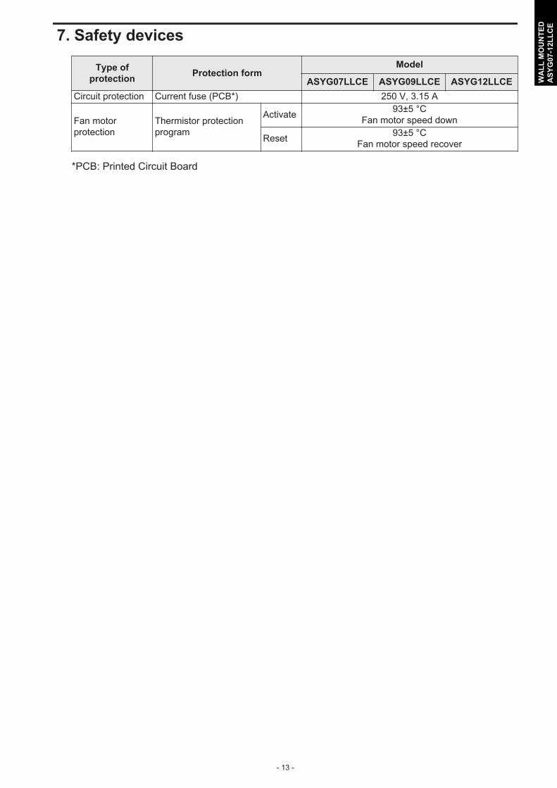
7. Safety devices
Type ofprotection Protection form
Model
ASYG07LLCE ASYG09LLCE ASYG12LLCECircuit protection Current fuse (PCB*) 250 V, 3.15 A
Fan motorprotection
Thermistor protectionprogram
Activate 93±5 °CFan motor speed down
Reset 93±5 °CFan motor speed recover
*PCB: Printed Circuit Board
- 13 -
WA
LL M
OU
NTE
DA
SYG
07-1
2LLC
E

8. Remote controller
8-1. Wireless remote controller¢ Overview
o
b
d
e
f
a
c
g
i
j
k
l
n
m
h
Display panel
u
r sp tq
a FAN buttonb SET buttonc SWING buttond START/STOP buttone RESET buttonf TIMER CANCEL buttong ON TIMER buttonh OFF TIMER buttoni SLEEP TIMER buttonj TEST RUN button
• Used only when installing the air conditioner, and shouldnot be used under normal conditions, as it will cause theindoor unit’s thermostat malfunction.
• If this button is pressed during normal operation, the in-door unit will switch to test operation mode, and the oper-ation indicator lamp and the timer indicator lamp on theindoor unit will begin to flash simultaneously.
• To stop the test operation mode, press the START/STOPbutton. Then, the air conditioner stops the operation.
k ECONOMY buttonl POWERFUL buttonm SET TEMP. (temperature) ( / ) button
• Sets desired temperature.• Sets remote controller custom code.
n MODE button• Switches operation mode (AUTO, COOL, DRY, FAN, and
HEAT).• Starts/ends the remote controller custom code (max. 4
types) change.
o Signal transmitterp Operating mode indicatorq Signal transmit indicatorr Temperature and time indicator
• Displays set temperature.• In timer setting, it displays the timer time. After finishing
the timer setting, set temperature will reappear.
s Swing indicatort Fan speed indicatoru Timer mode indicator
• Sleep timer
• OFF timer
• OFF-ON timer
• ON-OFF timer
• ON timer
DESIGN & TECHNICAL MANUAL
- 14 -
WA
LL M
OU
NTE
DA
SYG
07-1
2LLC
E

NOTE: Functions may differ by type of the indoor unit. For details, refer to the operationmanual.
- 15 -
WA
LL M
OU
NTE
DA
SYG
07-1
2LLC
E

¢ Specifications
Controller
Unit: mm
Front view Side view Rear view
139
1856
Top view
Size (H × W × D) mm 139 × 56 × 18Weight g 70 (without batteries)
Holder
Unit: mm
Front view Side view Bottom view
60.430.2
Ø 3.5
3.5 x 6.5
(hole)
(hole)
13.5
92
26.2
140
Size (H × W × D) mm 140 × 60.4 × 26.2Weight g 25
DESIGN & TECHNICAL MANUAL
- 16 -
WA
LL M
OU
NTE
DA
SYG
07-1
2LLC
E

9. Function settingsTo adjust the functions of this product according to the installation environment, various types offunction settings are available.
NOTE: Incorrect settings can cause a product malfunction.
9-1. Function settings by using remote controllerSome function settings can be changed on the remote controller. After confirming the setting pro-cedure and the content of each function setting, select appropriate functions for your installationenvironment.
NOTE: Incorrect settings can cause a product malfunction.
¢ Setting procedure by using wireless remote controllerThe function number and the associated setting value are displayed on the LCD of the remotecontroller. Follow the instructions written in the local setup procedure supplied with the remotecontroller, and select appropriate setting according to the installation environment.Before connecting the power supply of the indoor unit, reconfirm following items:• Piping air tight test and vacuuming have been performed firmly.• There is no wiring mistake.Then, connect the power supply of indoor unit.
Entering function setting mode:While pressing the FAN button and SET TEMP. ( ) button simultaneously, press the RESETbutton to enter the function setting mode.
STEP 1: Setting the remote controller custom codeUse the following steps to select the custom code of the remote controller. (Note that the air con-ditioner cannot receive a custom code if the air conditioner has not been set for the custom code.)The custom codes that are set through this process are applicable only to the signal in the func-tion setting.For details on how to set the custom codes through the normal process, refer to "Custom codesetting for wireless remote controller" on page 21.
1. Press the SET TEMP. ( ) ( ) buttons to change the customcode between → → → . Match the code on the display tothe air conditioner custom code. (Initially set to .) If the customcode does not need to be selected, press the MODE button, andproceed to STEP 2.
2. Press the MODE button to accept the custom code, and proceedto STEP 2.
*1: Small is displayed on the right of the custom code during thefunction setting.
*1
- 17 -
WA
LL M
OU
NTE
DA
SYG
07-1
2LLC
E

NOTES:• The air conditioner custom code is set to prior to shipment. To change the custom code,
contact your retailer.• The remote controller resets to custom code when the batteries on the remote controller are
replaced. If you use a custom code other than code , reset the custom code after replacingthe batteries.
• If you do not know the air conditioner custom code setting, try each of the custom codes ( → → → ) until you find the code that operates the air conditioner.
STEP 2: Selecting the function number and setting value
1. Press the SET TEMP. ( ) ( ) buttons to select the functionnumber. To switch between the left and right digits, press theMODE button.
2. Press the FAN button to proceed the setting value. To return thefunction number selection, press the FAN button again.
3. Press the SET TEMP. ( ) ( ) buttons to select the setting value.To switch between the left and right digits, press the MODE but-ton.
4. Press the SLEEP button, then after you hear the beep emittedfrom the indoor unit, the START/STOP button in the order to con-firm the settings.
5. Press the RESET button to cancel the function setting mode.
6. After completing the function setting, be sure to disconnect thepower supply and then reconnect it.
*1: Small is displayed on the right of the custom code during thefunction setting.
*1
*1
Function number
Setting value
CAUTIONAfter disconnect the power supply, wait 30 seconds or more before reconnecting it. The functionsetting will not become active unless the power supply is disconnected and then reconnected.
DESIGN & TECHNICAL MANUAL
- 18 -
WA
LL M
OU
NTE
DA
SYG
07-1
2LLC
E
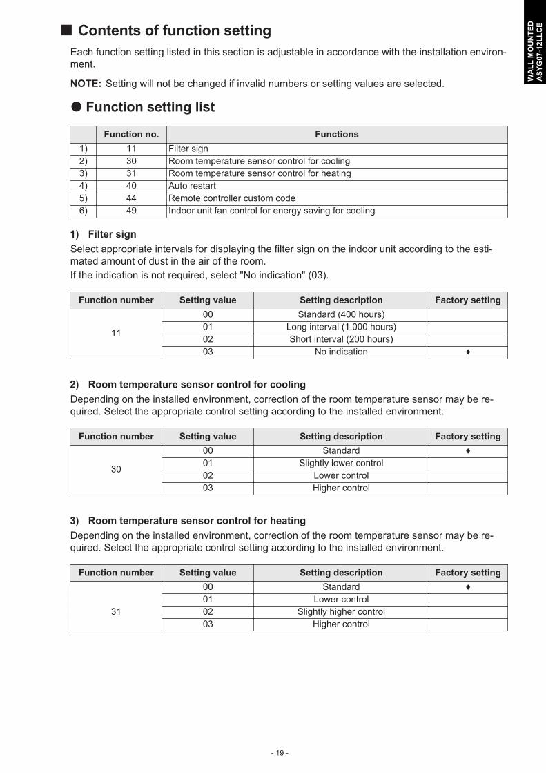
¢ Contents of function settingEach function setting listed in this section is adjustable in accordance with the installation environ-ment.
NOTE: Setting will not be changed if invalid numbers or setting values are selected.
Function setting list
Function no. Functions1) 11 Filter sign2) 30 Room temperature sensor control for cooling3) 31 Room temperature sensor control for heating4) 40 Auto restart5) 44 Remote controller custom code6) 49 Indoor unit fan control for energy saving for cooling
1) Filter signSelect appropriate intervals for displaying the filter sign on the indoor unit according to the esti-mated amount of dust in the air of the room.If the indication is not required, select "No indication" (03).
Function number Setting value Setting description Factory setting
11
00 Standard (400 hours)01 Long interval (1,000 hours)02 Short interval (200 hours)03 No indication ♦
2) Room temperature sensor control for coolingDepending on the installed environment, correction of the room temperature sensor may be re-quired. Select the appropriate control setting according to the installed environment.
Function number Setting value Setting description Factory setting
30
00 Standard ♦01 Slightly lower control02 Lower control03 Higher control
3) Room temperature sensor control for heatingDepending on the installed environment, correction of the room temperature sensor may be re-quired. Select the appropriate control setting according to the installed environment.
Function number Setting value Setting description Factory setting00 Standard ♦01 Lower control
31 02 Slightly higher control03 Higher control
- 19 -
WA
LL M
OU
NTE
DA
SYG
07-1
2LLC
E

4) Auto restartEnables or disables automatic restart after a power interruption.
Function number Setting value Setting description Factory setting
4000 Enable ♦01 Disable
NOTE: Auto restart is an emergency function such as for power outage etc. Do not attempt touse this function in normal operation. Be sure to operate the unit by remote controller orexternal device.
5) Remote controller custom code(Only for wireless remote controller)The indoor unit custom code can be changed. Select the appropriate custom code.
Function number Setting value Setting description Factory setting
44
00 A ♦01 B02 C03 D
6) Indoor unit fan control for energy saving for coolingEnables or disables the power-saving function by controlling the indoor unit fan rotation when theoutdoor unit is stopped during cooling operation.
Function number Setting value Setting description Factory setting
4900 Disable01 Enable ♦
00: When the outdoor unit is stopped, the indoor unit fan operates continuously following the set-ting on the remote controller.
01: When the outdoor unit is stopped, the indoor unit fan operates intermittently at a very lowspeed.
DESIGN & TECHNICAL MANUAL
- 20 -
WA
LL M
OU
NTE
DA
SYG
07-1
2LLC
E

9-2. Custom code setting for wireless remote controllerTo interconnect the air conditioner and the wireless remote controller, assignment of the customcode for the wireless remote controller is required.
NOTE: Air conditioner cannot receive a custom code if the air conditioner has not been set forthe custom code.
1. Press the MODE button for at least 5 seconds to display the current custom code. (Initiallyset to .)
2. Press the SET TEMP. ( or ) button to change the custom code between → → → .Match the code on the display to the air conditioner custom code.
3. Press the MODE button again. The custom code will be changed.
NOTES:• If no button is pressed within 30 seconds after the custom code is displayed, the system re-
turns to the original clock indicator. In this case, start again from step 1.• The air conditioner custom code is set to prior to shipment. To change the custom code,
contact your retailer.• The remote controller resets to custom code when the batteries in the remote controller are
replaced. If you use a custom code other than code , reset the appropriate custom code af-ter replacing the batteries. If you do not know the assigned code for the air conditioner, tryeach of the custom code ( → → → ) until you find the code which operates the air condi-tioner.
- 21 -
WA
LL M
OU
NTE
DA
SYG
07-1
2LLC
E

10. AccessoriesPart name Exterior Q’ty Part name Exterior Q’ty
Operating manual 1 Battery 2
Installation manual 1 Cloth tape 1
Wall hook bracket 1 Tapping screw (large),M4 × 25 mm 5
Remote controller 1
DESIGN & TECHNICAL MANUAL
- 22 -
WA
LL M
OU
NTE
DA
SYG
07-1
2LLC
E

Part 2. OUTDOOR UNITSINGLE TYPE:AOYG07LLCEAOYG09LLCEAOYG12LLCE

1. SpecificationsType Inverter heat pump
Model name AOYG07LLCE AOYG09LLCE AOYG12LLCEPower supply 230 V ~ 50 HzAvailable voltage range 198—264 VStarting current A 3.0 3.5 5.4
FanAirflow rate
Coolingm3/h
1,670 1,830Heating 1,470 1,600
Type × Q'ty Propeller fan × 1Motor output W 23
Sound pressure level *1Cooling
dB (A)47 50
Heating 48 51
Sound power levelCooling
dB (A)61 65
Heating 61 65
Heat exchanger type
Dimensions(H × W × D) mm
650 × 504 × 18.2642 × 504 × 18.2612 × 504 × 18.2
Fin pitch 1.30 1.40Rows × Stages 1 × 24 2 × 24Pipe type Copper
Fin typeType (Material) Corrugate (Aluminum)Surface treatment Corrosion resistance (Blue fin)
CompressorType × Q'ty Rotary × 1Motor output W 610 670
RefrigerantType (Global warming potential) R410A (1975)Charge g 650 850
Refrigerant oilType POE (VG74)Amount cm3 370
EnclosureMaterial Steel sheet
ColorBeige
Approximate color of MUNSELL 10YR7.5/1.0Dimensions(H × W × D)
Netmm
535 × 663 × 293Gross 595 × 790 × 395
WeightNet
kg24 26
Gross 27 29
Connection pipe
SizeLiquid
mm (in)Ø 6.35 (Ø 1/4)
Gas Ø 9.52 (Ø 3/8)Method FlarePre-charge length
m15
Max. length 20Max. height difference 15
Operation rangeCooling
°C-10 to 43
Heating -15 to 24
Drain hoseMaterial LDPESize mm Ø 13.0 (I. D.), Ø 16.0 to Ø 16.7 (O. D.)
NOTES:• Specifications are based on the following conditions:
– Cooling: Indoor temperature of 27 °CDB/19 °CWB, and outdoor temperature of 35 °CDB/24 °CWB.– Heating: Indoor temperature of 20 °CDB/15 °CWB, and outdoor temperature of 7 °CDB/6 °CWB.– Pipe length: 5 m, Height difference: 0 m.
• Protective function might work when using it outside the operation range.• *1: Sound pressure level
– Measured values in manufacturer’s anechoic chamber.– Because of the surrounding sound environment, the sound levels measured in actual installation conditions might be higher than the specified values here.
DESIGN & TECHNICAL MANUAL
- 24 -
OU
TDO
OR
UN
ITA
OYG
07-1
2LLC
E

2. Dimensions
2-1. Models:AOYG07LLCE, AOYG09LLCE, and AOYG12LLCE
Top view
Unit: mm
Front view Side view
20 663 68 293
Drain hole 30330
454(Pitch of bolt)
103
535
15
48
352
330
- 25 -
OU
TDO
OR
UN
ITA
OYG
07-1
2LLC
E

3. Installation space
3-1. Models:AOYG07LLCE, AOYG09LLCE, and AOYG12LLCE¢ Space requirement
Provide sufficient installation space for product safety.
Single outdoor unit installation• When the upper space is open:
Unit: mm
When there are obstacles at the rear only. When there are obstacles at the rear andsides.
100 or more250 or more
100 or more100 or more
When there are obstacles at the front only. When there are obstacles at the front andrear.
600 or more 600 or more
100 or more
• When there is an obstruction in the upper space:
Unit: mm
When there are obstacles at the rear andabove.
When there are obstacles at the rear, sides,and above.
100 or more
Max. 200
600 or more600 or more
100 or more
250 or more
100 or more
Max. 200
DESIGN & TECHNICAL MANUAL
- 26 -
OU
TDO
OR
UN
ITA
OYG
07-1
2LLC
E

Multiple outdoor unit installation• When the upper space is open:
Unit: mm
When there are obstacles at the rear only. When there are obstacles at the front only.
200or more
1,000 or more
When there are obstacles at the front andrear.
200 or more1,000 or more
• When there is an obstruction in the upper space:
Unit: mm
When there are obstacles at the rear and above.
1,500 or more
200 or more
Max. 300
- 27 -
OU
TDO
OR
UN
ITA
OYG
07-1
2LLC
E

Outdoor unit installation in multi-row
Unit: mm
Single parallel unit arrangement Multiple parallel unit arrangement
100 or more
200 or more500 or more
1,000 or more200 or more
400 or more1,000 or more
2,000 or more
200 or more
NOTES:• If the space is larger than stated above, the condition will be the same as when there is no
obstacle.• Height above the floor level should be 50 mm or more.• When installing the outdoor unit, be sure to open the front and left side to obtain better opera-
tion efficiency.
CAUTION• Do not install the outdoor unit in two-stage where the drain water could freeze. Otherwise the
drainage from the upper unit may form ice and cause a malfunction of the lower unit.• When the outdoor temperature is 0 °C or less, do not use the accessory drain pipe and drain
cap. If the drain pipe and drain cap are used, the drain water in the pipe may freeze in ex-tremely cold climate. (For reverse cycle model only.)
• In area with heavy snowfall, if the inlet and outlet of the outdoor unit is blocked with snow, itmight become difficult to get warm, and it is likely to cause product malfunction. Construct acanopy and a pedestal, or place the unit on a high stand that is locally installed.
DESIGN & TECHNICAL MANUAL
- 28 -
OU
TDO
OR
UN
ITA
OYG
07-1
2LLC
E

4. Refrigerant circuit
4-1. Models:AOYG07LLCE, AOYG09LLCE, and AOYG12LLCEHeat exchanger
(INDOOR)
ThD
ThD
ThP
ThP
ThR
ThR
ThHO
ThHO
ThO
ThO
3-wayvalve
Muffler
: Cooling: Heating
: Thermistor (Discharge temperature): Thermistor (Outdoor temperature): Thermistor (Heat exchanger out temperature)
: Thermistor (Room temperature): Thermistor (Pipe temperature)
Com
pres
sor
4-way valveStrainer
Expansion valve
Strainer
2-wayvalve
- 29 -
OU
TDO
OR
UN
ITA
OYG
07-1
2LLC
E

5. Wiring diagrams
5-1. Models:AOYG07LLCE, AOYG09LLCE, and AOYG12LLCE
DESIGN & TECHNICAL MANUAL
- 30 -
OU
TDO
OR
UN
ITA
OYG
07-1
2LLC
E

6. Capacity compensation rate for pipe length and heightdifference
Height difference HIndoor unit is higher than outdoor unit *1 Indoor unit is lower than outdoor unit *2
Indoor unit
Indoor unit
Connection pipe
Outdoor unit
Outdoor unit
Connection pipe
H H
6-1. Models:AOYG07LLCE and AOYG09LLCENOTE: Values mentioned in the table are calculated based on the maximum capacity.
COOLINGPipe length (m)
5 7.5 10 15 20
Hei
ght d
iffer
ence
H (m
)
Indoor unit is higher thanoutdoor unit *1
15 - - - 0.872 0.91010 - - 0.961 0.886 0.9257.5 - 0.979 0.965 0.890 0.9295 0.992 0.983 0.969 0.893 0.9330 1.000 0.991 0.976 0.901 0.940
Indoor unit is lower thanoutdoor unit *2
-5 1.000 0.991 0.976 0.901 0.940-7.5 - 0.991 0.976 0.901 0.940-10 - - 0.976 0.901 0.940-15 - - - 0.901 0.940
HEATINGPipe length (m)
5 7.5 10 15 20
Hei
ght d
iffer
ence
H (m
)
Indoor unit is higher thanoutdoor unit *1
15 - - - 0.832 0.82210 - - 0.917 0.832 0.8227.5 - 0.961 0.917 0.832 0.8225 1.000 0.961 0.917 0.832 0.8220 1.000 0.961 0.917 0.832 0.822
Indoor unit is lower thanoutdoor unit *2
-5 0.995 0.956 0.912 0.828 0.818-7.5 - 0.954 0.910 0.826 0.816-10 - - 0.908 0.824 0.814-15 - - - 0.815 0.805
- 31 -
OU
TDO
OR
UN
ITA
OYG
07-1
2LLC
E

6-2. Model:AOYG12LLCENOTE: Values mentioned in the table are calculated based on the maximum capacity.
COOLINGPipe length (m)
5 7.5 10 15 20
Hei
ght d
iffer
ence
H (m
)
Indoor unit is higher thanoutdoor unit *1
15 - - - 0.858 0.86810 - - 0.929 0.872 0.8827.5 - 0.960 0.933 0.876 0.8855 0.992 0.964 0.937 0.879 0.8890 1.000 0.972 0.944 0.887 0.896
Indoor unit is lower thanoutdoor unit *2
-5 1.000 0.972 0.944 0.887 0.896-7.5 - 0.972 0.944 0.887 0.896-10 - - 0.944 0.887 0.896-15 - - - 0.887 0.896
HEATINGPipe length (m)
5 7.5 10 15 20
Hei
ght d
iffer
ence
H (m
)
Indoor unit is higher thanoutdoor unit *1
15 - - - 0.896 0.87910 - - 0.968 0.890 0.8797.5 - 0.994 0.968 0.896 0.8795 1.000 0.994 0.968 0.896 0.8790 1.000 0.994 0.968 0.896 0.879
Indoor unit is lower thanoutdoor unit *2
-5 0.995 0.989 0.963 0.891 0.875-7.5 - 0.987 0.961 0.889 0.873-10 - - 0.959 0.887 0.871-15 - - - 0.878 0.862
DESIGN & TECHNICAL MANUAL
- 32 -
OU
TDO
OR
UN
ITA
OYG
07-1
2LLC
E

7. Additional charge calculation
7-1. Models:AOYG07LLCE and AOYG09LLCERefrigerant type R410ARefrigerant amount g 650
¢ Refrigerant chargeTotal pipe length m 15 or less 20 (Max.)
20 g/mAdditional charge g 0 100
7-2. Model:AOYG12LLCERefrigerant type R410ARefrigerant amount g 850
¢ Refrigerant chargeTotal pipe length m 15 or less 20 (Max.)
20 g/mAdditional charge g 0 100
- 33 -
OU
TDO
OR
UN
ITA
OYG
07-1
2LLC
E

8. Airflow
8-1. Models:AOYG07LLCE and AOYG09LLCE
Cooling
m3/h 1,670l/s 464
CFM 983
Heating
m3/h 1,470l/s 408
CFM 865
8-2. Model:AOYG12LLCE
Cooling
m3/h 1,830l/s 508
CFM 1,077
Heating
m3/h 1,600l/s 444
CFM 942
DESIGN & TECHNICAL MANUAL
- 34 -
OU
TDO
OR
UN
ITA
OYG
07-1
2LLC
E

9. Operation noise (sound pressure)
9-1. Noise level curve¢ Model:AOYG07LLCE Cooling
Oct
ave
band
sou
nd p
ress
ure
leve
l, dB
: (0
dB=0
.000
2 µb
ar)
Octave band center frequency,Hz
80
70
60
50
40
30
20
10
063 125 250 500 1,000 2,000 4,000 8,000
NC-65
NC-60
NC-55
NC-50
NC-45
NC-40
NC-35
NC-30
NC-25
NC-20
NC-15
Heating
Oct
ave
band
sou
nd p
ress
ure
leve
l, dB
: (0
dB=0
.000
2 µb
ar)
Octave band center frequency,Hz
80
70
60
50
40
30
20
10
063 125 250 500 1,000 2,000 4,000 8,000
NC-65
NC-60
NC-55
NC-50
NC-45
NC-40
NC-35
NC-30
NC-25
NC-20
NC-15
¢ Model:AOYG09LLCE Cooling
Oct
ave
band
sou
nd p
ress
ure
leve
l, dB
: (0
dB=0
.000
2 µb
ar)
Octave band center frequency,Hz
80
70
60
50
40
30
20
10
063 125 250 500 1,000 2,000 4,000 8,000
NC-65
NC-60
NC-55
NC-50
NC-45
NC-40
NC-35
NC-30
NC-25
NC-20
NC-15
Heating
Oct
ave
band
sou
nd p
ress
ure
leve
l, dB
: (0
dB=0
.000
2 µb
ar)
Octave band center frequency,Hz
80
70
60
50
40
30
20
10
063 125 250 500 1,000 2,000 4,000 8,000
NC-65
NC-60
NC-55
NC-50
NC-45
NC-40
NC-35
NC-30
NC-25
NC-20
NC-15
- 35 -
OU
TDO
OR
UN
ITA
OYG
07-1
2LLC
E

¢ Model:AOYG12LLCE Cooling
Oct
ave
band
sou
nd p
ress
ure
leve
l, dB
: (0
dB=0
.000
2 µb
ar)
Octave band center frequency,Hz
80
70
60
50
40
30
20
10
063 125 250 500 1,000 2,000 4,000 8,000
NC-65
NC-60
NC-55
NC-50
NC-45
NC-40
NC-35
NC-30
NC-25
NC-20
NC-15
Heating
Oct
ave
band
sou
nd p
ress
ure
leve
l, dB
: (0
dB=0
.000
2 µb
ar)
Octave band center frequency,Hz
80
70
60
50
40
30
20
10
063 125 250 500 1,000 2,000 4,000 8,000
NC-65
NC-60
NC-55
NC-50
NC-45
NC-40
NC-35
NC-30
NC-25
NC-20
NC-15
DESIGN & TECHNICAL MANUAL
- 36 -
OU
TDO
OR
UN
ITA
OYG
07-1
2LLC
E

9-2. Sound level check point
1 m
MicrophoneMicrophone
Rear
Airflow
Rear viewSide view
NOTE: Detailed shape of the actual outdoor unit might be slightly different from the one illustrat-ed above.
- 37 -
OU
TDO
OR
UN
ITA
OYG
07-1
2LLC
E

10. Electrical characteristicsModel name AOYG07LLCE AOYG09LLCE AOYG12LLCEPowersupply
Voltage V 230 ~Frequency Hz 50
Max operating current *1 A 7.5 7.5 9.0Starting current A 3.0 3.5 5.4
Wiringspec. *2
Circuit breaker current A 15Power cable mm2 1.5Connection cable *3 mm2 1.5
Limited wiring length m 21
*1: Maximum current is the total current of the indoor unit and the outdoor unit.*2: Selected sample based on Japan Electrotechnical Standards and Codes Committee E0005.As the regulations of wire size and circuit breaker differ in each country or region, select appropri-ate devices complied to the regional standard.*3: Limit voltage drop to less than 2%. If voltage drop is 2% or more, increase cable conductorsize.
DESIGN & TECHNICAL MANUAL
- 38 -
OU
TDO
OR
UN
ITA
OYG
07-1
2LLC
E

11. Safety devices
Type ofprotection Protection form
Model
AOYG07LLCE AOYG09LLCE AOYG12LLCE
Circuit protection Current fuse (Main PCB)250 V, 25 A250 V, 5 A
Fan motorprotection
Terminal protectionprogram
Activate 100±15 °CFan motor stop
Reset 95±10 °CFan motor restart
Compressorprotection
Terminal protectionprogram(Discharge temp.)
Activate 110 °CCompressor stop
Reset After 7 minutesCompressor restart
- 39 -
OU
TDO
OR
UN
ITA
OYG
07-1
2LLC
E

12. AccessoriesPart name Exterior Q’ty Part name Exterior Q’ty
Drain pipe 1
DESIGN & TECHNICAL MANUAL
- 40 -
OU
TDO
OR
UN
ITA
OYG
07-1
2LLC
E