Design Studies for Hydrogen Fuel Cell Powered Unmanned ...thb/Publications/Conceptual... · Design...
16
American Institute of Aeronautics and Astronautics 1 Design Studies for Hydrogen Fuel Cell Powered Unmanned Aerial Vehicles Thomas H. Bradley * , Blake A. Moffitt † , Thomas F. Fuller ‡ , Dimitri Mavris § , David E. Parekh ** Georgia Institute of Technology, Atlanta, Georgia, 30332 This paper presents two comparisons of design methods for fuel cell powered unmanned aerial vehicles. Previous studies of fuel cell powered aircraft have used design methods that contain intrinsic assumptions regarding the design of fuel cell powerplant and regarding the interactions between the powerplant and aircraft application. This study seeks to understand the effects of these design assumptions on the powerplant structure and the aircraft performance of fuel cell powered aircraft. A comparison is constructed by developing a multidisciplinary modeling and design environment that does not contain the assumption suggested in previous studies. Design assumptions from previous studies can then be imposed on the more complete design environment to determine the performance costs and morphological changes caused by the design assumptions. In the first design study, results show that designing fuel cell powered aircraft using automotive-type fuel cell subsystem design rules leads to a low efficiency powerplant and a low performance aircraft in long-endurance and long-range UAV applications. The second design study shows that designing the long endurance aircraft powerplant towards maximum specific energy leads to suboptimal aircraft performance, especially for long-endurance UAV applications. I. Introduction HE long endurance unmanned aerial vehicle (UAV) has significant value as a low-cost, autonomous reconnaissance and remote sensing platform for research, commercial and military missions. Fuel cell powerplants are of interest in this application because of the potential to construct powerplants of high specific energy, low noise, low thermal signature, and improved environmental compatibility. Because of these performance advantages, fuel cells have recently found their first aviation applications as powerplants for small-scale long-endurance and long-range UAVs. Table 1 lists the demonstrated fuel cell powered UAVs known to the authors. In 2003, AeroVironment Inc., a vehicle design and manufacturing company in Monrovia, California, built and flew the first fuel cell powered aircraft. Its monopolar polymer electrolyte membrane (PEM) fuel cell system consumes hydrogen from a sodium borohydride reaction vessel. Between those first flights and the present, a number of researchers and commercial entities have developed fuel cell powered UAVs of increasing scale and capability. A majority of the demonstration aircraft have used a PEM fuel cell. A variety of hydrogen storage systems have been used including gaseous pressure vessels, chemical hydrates and low pressure cryogenic liquid hydrogen tanks. A notable technological outlier is the propane-fueled, solid-oxide fuel cell (SOFC) UAV that was constructed in 2006 by Advanced Materials Inc. * Assistant Professor, Colorado State University Department of Mechanical Engineering, Fort Collins, Colorado 80521, AIAA Member. † Graduate Student, The Daniel Guggenheim School of Aerospace Engineering, 270 Ferst Drive N.W. Atlanta, Georgia 30332-0150, AIAA Student Member. ‡ Professor, School of Chemical & Biomolecular Engineering, 311 Ferst Drive N.W., Atlanta, Georgia 30332-0100. § Boeing Professor of Advanced Aerospace Systems Analysis, The Daniel Guggenheim School of Aerospace Engineering, 270 Ferst Drive N.W. Atlanta, Georgia 30332-0150, Associate Fellow of AIAA. ** VP Research and Director, United Technologies Research Center, 411 Silver Lane MS129-01, East Hartford, Connecticut 06108, Associate Fellow of AIAA. T
Transcript of Design Studies for Hydrogen Fuel Cell Powered Unmanned ...thb/Publications/Conceptual... · Design...
American Institute of Aeronautics and Astronautics
1
Design Studies for Hydrogen Fuel Cell
Powered Unmanned Aerial Vehicles
Thomas H. Bradley*, Blake A. Moffitt†, Thomas F. Fuller‡, Dimitri Mavris§, David E. Parekh**
Georgia Institute of Technology, Atlanta, Georgia, 30332
This paper presents two comparisons of design methods for fuel cell powered unmanned
aerial vehicles. Previous studies of fuel cell powered aircraft have used design methods that
contain intrinsic assumptions regarding the design of fuel cell powerplant and regarding the
interactions between the powerplant and aircraft application. This study seeks to
understand the effects of these design assumptions on the powerplant structure and the
aircraft performance of fuel cell powered aircraft. A comparison is constructed by
developing a multidisciplinary modeling and design environment that does not contain the
assumption suggested in previous studies. Design assumptions from previous studies can
then be imposed on the more complete design environment to determine the performance
costs and morphological changes caused by the design assumptions. In the first design study, results show that designing fuel cell powered aircraft using automotive-type fuel cell
subsystem design rules leads to a low efficiency powerplant and a low performance aircraft
in long-endurance and long-range UAV applications. The second design study shows that
designing the long endurance aircraft powerplant towards maximum specific energy leads to
suboptimal aircraft performance, especially for long-endurance UAV applications.
I. Introduction
HE long endurance unmanned aerial vehicle (UAV) has significant value as a low-cost, autonomous
reconnaissance and remote sensing platform for research, commercial and military missions. Fuel cell
powerplants are of interest in this application because of the potential to construct powerplants of high specific
energy, low noise, low thermal signature, and improved environmental compatibility.
Because of these performance advantages, fuel cells have recently found their first aviation applications as
powerplants for small-scale long-endurance and long-range UAVs. Table 1 lists the demonstrated fuel cell powered
UAVs known to the authors. In 2003, AeroVironment Inc., a vehicle design and manufacturing company in
Monrovia, California, built and flew the first fuel cell powered aircraft. Its monopolar polymer electrolyte
membrane (PEM) fuel cell system consumes hydrogen from a sodium borohydride reaction vessel. Between those
first flights and the present, a number of researchers and commercial entities have developed fuel cell powered
UAVs of increasing scale and capability. A majority of the demonstration aircraft have used a PEM fuel cell. A variety of hydrogen storage systems have been used including gaseous pressure vessels, chemical hydrates and low
pressure cryogenic liquid hydrogen tanks. A notable technological outlier is the propane-fueled, solid-oxide fuel
cell (SOFC) UAV that was constructed in 2006 by Advanced Materials Inc.
*Assistant Professor, Colorado State University Department of Mechanical Engineering, Fort Collins, Colorado
80521, AIAA Member. †Graduate Student, The Daniel Guggenheim School of Aerospace Engineering, 270 Ferst Drive N.W. Atlanta,
Georgia 30332-0150, AIAA Student Member. ‡Professor, School of Chemical & Biomolecular Engineering, 311 Ferst Drive N.W., Atlanta, Georgia 30332-0100. §Boeing Professor of Advanced Aerospace Systems Analysis, The Daniel Guggenheim School of Aerospace
Engineering, 270 Ferst Drive N.W. Atlanta, Georgia 30332-0150, Associate Fellow of AIAA. **VP Research and Director, United Technologies Research Center, 411 Silver Lane MS129-01, East Hartford,
Connecticut 06108, Associate Fellow of AIAA.
T
American Institute of Aeronautics and Astronautics
2
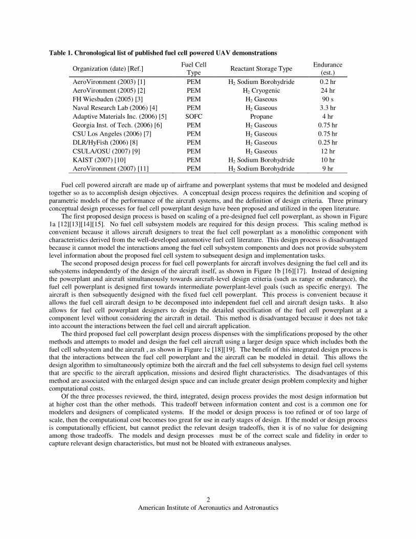
Table 1. Chronological list of published fuel cell powered UAV demonstrations
Organization (date) [Ref.] Fuel Cell
Type Reactant Storage Type
Endurance
(est.)
AeroVironment (2003) [1] PEM H2 Sodium Borohydride 0.2 hr
AeroVironment (2005) [2] PEM H2 Cryogenic 24 hr
FH Wiesbaden (2005) [3] PEM H2 Gaseous 90 s
Naval Research Lab (2006) [4] PEM H2 Gaseous 3.3 hr
Adaptive Materials Inc. (2006) [5] SOFC Propane 4 hr
Georgia Inst. of Tech. (2006) [6] PEM H2 Gaseous 0.75 hr
CSU Los Angeles (2006) [7] PEM H2 Gaseous 0.75 hr
DLR/HyFish (2006) [8] PEM H2 Gaseous 0.25 hr
CSULA/OSU (2007) [9] PEM H2 Gaseous 12 hr
KAIST (2007) [10] PEM H2 Sodium Borohydride 10 hr
AeroVironment (2007) [11] PEM H2 Sodium Borohydride 9 hr
Fuel cell powered aircraft are made up of airframe and powerplant systems that must be modeled and designed
together so as to accomplish design objectives. A conceptual design process requires the definition and scoping of
parametric models of the performance of the aircraft systems, and the definition of design criteria. Three primary
conceptual design processes for fuel cell powerplant design have been proposed and utilized in the open literature.
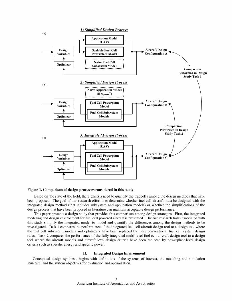
The first proposed design process is based on scaling of a pre-designed fuel cell powerplant, as shown in Figure
1a [12][13][14][15]. No fuel cell subsystem models are required for this design process. This scaling method is
convenient because it allows aircraft designers to treat the fuel cell powerplant as a monolithic component with
characteristics derived from the well-developed automotive fuel cell literature. This design process is disadvantaged
because it cannot model the interactions among the fuel cell subsystem components and does not provide subsystem
level information about the proposed fuel cell system to subsequent design and implementation tasks. The second proposed design process for fuel cell powerplants for aircraft involves designing the fuel cell and its
subsystems independently of the design of the aircraft itself, as shown in Figure 1b [16][17]. Instead of designing
the powerplant and aircraft simultaneously towards aircraft-level design criteria (such as range or endurance), the
fuel cell powerplant is designed first towards intermediate powerplant-level goals (such as specific energy). The
aircraft is then subsequently designed with the fixed fuel cell powerplant. This process is convenient because it
allows the fuel cell aircraft design to be decomposed into independent fuel cell and aircraft design tasks. It also
allows for fuel cell powerplant designers to design the detailed specification of the fuel cell powerplant at a
component level without considering the aircraft in detail. This method is disadvantaged because it does not take
into account the interactions between the fuel cell and aircraft application.
The third proposed fuel cell powerplant design process dispenses with the simplifications proposed by the other
methods and attempts to model and design the fuel cell aircraft using a larger design space which includes both the
fuel cell subsystem and the aircraft , as shown in Figure 1c [18][19]. The benefit of this integrated design process is that the interactions between the fuel cell powerplant and the aircraft can be modeled in detail. This allows the
design algorithm to simultaneously optimize both the aircraft and the fuel cell subsystems to design fuel cell systems
that are specific to the aircraft application, missions and desired flight characteristics. The disadvantages of this
method are associated with the enlarged design space and can include greater design problem complexity and higher
computational costs.
Of the three processes reviewed, the third, integrated, design process provides the most design information but
at higher cost than the other methods. This tradeoff between information content and cost is a common one for
modelers and designers of complicated systems. If the model or design process is too refined or of too large of
scale, then the computational cost becomes too great for use in early stages of design. If the model or design process
is computationally efficient, but cannot predict the relevant design tradeoffs, then it is of no value for designing
among those tradeoffs. The models and design processes must be of the correct scale and fidelity in order to capture relevant design characteristics, but must not be bloated with extraneous analyses.
American Institute of Aeronautics and Astronautics
3
Figure 1. Comparison of design processes considered in this study
Based on the state of the field, there exists a need to quantify the tradeoffs among the design methods that have
been proposed. The goal of this research effort is to determine whether fuel cell aircraft must be designed with the
integrated design method (that includes subsystem and application models) or whether the simplifications of the
design process that have been proposed in literature can maintain acceptable design performance.
This paper presents a design study that provides this comparison among design strategies. First, the integrated modeling and design environment for fuel cell powered aircraft is presented. The two research tasks associated with
this study simplify the integrated model to model and quantify the differences among the design methods to be
investigated. Task 1 compares the performance of the integrated fuel cell aircraft design tool to a design tool where
the fuel cell subsystem models and optimizers have been replaced by more conventional fuel cell system design
rules. Task 2 compares the performance of the fully integrated multi-level fuel cell aircraft design tool to a design
tool where the aircraft models and aircraft level-design criteria have been replaced by powerplant-level design
criteria such as specific energy and specific power.
II. Integrated Design Environment
Conceptual design synthesis begins with definitions of the systems of interest, the modeling and simulation
structure, and the system objectives for evaluation and optimization.
Application Model
(UAV)
Naïve Fuel Cell
Subsystem Model
1) Simplified Design Process
Naïve Application Model
(E mpower-1
)
2) Simplified Design Process
Scalable Fuel Cell
Powerplant Model
3) Integrated Design Process
Aircraft Design
Configuration C
Fuel Cell Powerplant
Model
Fuel Cell Subsystem
Models
Application Model
(UAV)
Fuel Cell Powerplant
Model
Fuel Cell Subsystem
Models
Design
Variables
(a)
(b)
(c)
Aircraft Design
Configuration B
Aircraft Design
Configuration A
Comparison
Performed in Design
Study Task 2
Design
Variables
Design
Variables
Optimizer
Optimizer
Optimizer
Comparison
Performed in Design
Study Task 1
American Institute of Aeronautics and Astronautics
4
A. Conceptual Design This design study takes place at the stage of conceptual aircraft design. The goal of conceptual design is to
define the subsystem interactions, configuration, layout, dimensions and performance of the integrated airframe and
powerplant system. For this study, we are primarily interested in the synthesis and comparison of near-term
available, small-scale, low altitude fuel cell powered UAVs that are able to accomplish the generic, long-endurance
mission profiles shown in Figure 1. These restrictions of design scope place requirements and limitations on the models used to represent the
performance of the aircraft systems. For instance, the airframe model is designed to be able to model the static
performance of highly generic UAVs at low Mach number, at a scale of between 5 kg and 50 kg of gross takeoff
weight. As such, the baseline airframe is a conventional high wing monoplane, with rear empennage, driven by
tractor propeller. To model the airframe, this study includes parametric model representations of the airframe
aerodynamics, structures, mass, stability, geometry, mission performance, payload, and propulsion. Details such as
airframe dynamics, rigorous aerodynamic optimization, manufacturability, and costs are left for later stages of
design.
The powerplant model is designed to be able to model the steady-state performance of a PEM fuel cell
powerplant delivering DC electrical power to a propulsion electric motor and payload. The PEM fuel cell
technology is chosen for this study because of its high technology readiness factor, relatively high specific power
and robustness in mobile applications. To model the powerplant, this study includes parametric model representations of the powerplant electrochemical performance, static control, mass, geometry, and component
power consumption. Again, low-level implementation challenges are left for later stages of design.
B. Powerplant and Aircraft Modeling To make the analysis of the aircraft tractable, the multidisciplinary analysis (MDA) is decomposed into
contributing analyses (CAs). Each CA describes the modeled performance of a single aircraft component as a
function of design variables which are inputs to the multidisciplinary analysis and as a function of CA variables,
which are outputs from other CAs. Thus, to analyze a particular conceptual design, the design variables must be
chosen to define the design point in the design space. The MDA is then solved iteratively to reach a converged
solution that defines the states of all of the CAs, thereby defining the aircraft performance at that design point.
Hydrogen Storage Contributing Analyses
Compressed gaseous hydrogen storage systems are considered for this design study. The compressed hydrogen
storage system is modeled as a composite over-wrapped pressure vessel using mechanics of materials with data from
the literature, as shown in Table 2. The hydrogen tank is of cylindrical geometry with hemispherical end caps. The
tank is subjected only to loading due to the uniform pressure difference between the internal hydrogen pressure and
the external atmospheric pressure. In general, composite hydrogen tanks require metallic or polymeric liners to
reduce the hydrogen leak rate. The aluminum tank liner is assumed to be of constant thickness and does not
contribute to the strength of the tank, but does contribute to its weight. The thickness of the composite overwrap is
specified to resist the hoop stress and the axial stress due to the pressure loads. The total composite thickness is
equal to:
( ) ( )
−+
−⋅=
maxcomp
2
maxcomp
2
2σσatmHatmH
fscomposite
PPrPPrxt , (1)
and the total tank mass is calculated using the formula:
2regcompositelinertank )()1( Hmount mmmmfm +++⋅+= (2)
American Institute of Aeronautics and Astronautics
5
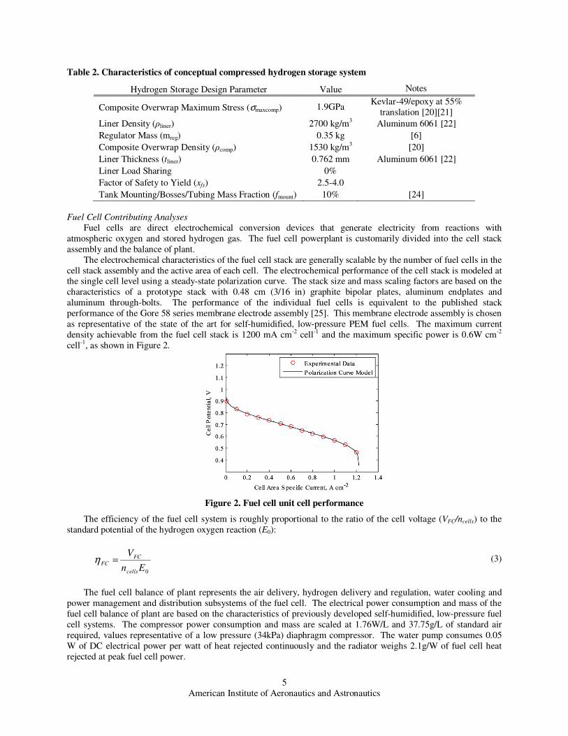
Table 2. Characteristics of conceptual compressed hydrogen storage system
Hydrogen Storage Design Parameter Value Notes
Composite Overwrap Maximum Stress (σmaxcomp) 1.9GPa Kevlar-49/epoxy at 55%
translation [20][21]
Liner Density (ρliner) 2700 kg/m3 Aluminum 6061 [22]
Regulator Mass (mreg) 0.35 kg [6]
Composite Overwrap Density (ρcomp) 1530 kg/m3 [20]
Liner Thickness (tliner) 0.762 mm Aluminum 6061 [22]
Liner Load Sharing 0%
Factor of Safety to Yield (xfs) 2.5-4.0
Tank Mounting/Bosses/Tubing Mass Fraction (fmount) 10% [24]
Fuel Cell Contributing Analyses
Fuel cells are direct electrochemical conversion devices that generate electricity from reactions with
atmospheric oxygen and stored hydrogen gas. The fuel cell powerplant is customarily divided into the cell stack
assembly and the balance of plant.
The electrochemical characteristics of the fuel cell stack are generally scalable by the number of fuel cells in the
cell stack assembly and the active area of each cell. The electrochemical performance of the cell stack is modeled at the single cell level using a steady-state polarization curve. The stack size and mass scaling factors are based on the
characteristics of a prototype stack with 0.48 cm (3/16 in) graphite bipolar plates, aluminum endplates and
aluminum through-bolts. The performance of the individual fuel cells is equivalent to the published stack
performance of the Gore 58 series membrane electrode assembly [25]. This membrane electrode assembly is chosen
as representative of the state of the art for self-humidified, low-pressure PEM fuel cells. The maximum current
density achievable from the fuel cell stack is 1200 mA cm-2 cell-1 and the maximum specific power is 0.6W cm-2
cell-1, as shown in Figure 2.
Figure 2. Fuel cell unit cell performance
The efficiency of the fuel cell system is roughly proportional to the ratio of the cell voltage (VFC/ncells) to the
standard potential of the hydrogen oxygen reaction (E0):
0En
V
cells
FC
FC =η (3)
The fuel cell balance of plant represents the air delivery, hydrogen delivery and regulation, water cooling and
power management and distribution subsystems of the fuel cell. The electrical power consumption and mass of the
fuel cell balance of plant are based on the characteristics of previously developed self-humidified, low-pressure fuel
cell systems. The compressor power consumption and mass are scaled at 1.76W/L and 37.75g/L of standard air
required, values representative of a low pressure (34kPa) diaphragm compressor. The water pump consumes 0.05
W of DC electrical power per watt of heat rejected continuously and the radiator weighs 2.1g/W of fuel cell heat
rejected at peak fuel cell power.
American Institute of Aeronautics and Astronautics
6
Airframe Contributing Analyses
For conceptual design calculations, the wing airfoil used is a Selig-Donovan 7032. This airfoil is a highly
efficient, low-Reynolds number airfoil and is used for all of the aircraft configurations considered. The
aerodynamic contributing analysis was conducted using both offline and online calculations. Wings2004, a
potential flow analysis code, was used offline to calculate induced drag, lift, and interaction effects between the wing and tail [27]. The parasite drag of the wing was also calculated offline using profile drag numbers tabulated
versus Reynold number based on wind tunnel tests of the Selig-Donovan 7032 airfoil. Online, the Aerodynamic CA
estimates the fuselage lift and drag characteristics, and uses this information with the offline values to estimate the
parasite drag of the aircraft and develop a drag polar of the aircraft. Most of the online calculations are based on the
methods and equations of Roskam [26].
Empennage sections were analyzed assuming a NACA 0009 airfoil. Sizing of the empennage is based on
maintaining a static margin (scaled by the wing chord) of 20 and an aircraft yawing moment coefficient of 0.15.
Sizing of the tail is accomplished using an offline iterative method involving Wings2004 and was scaled online
using the resulting tail volume coefficients.
The propeller performance contributing analysis is based on Goldstein’s vortex theory of screw propellers using
the Betz condition [28]. The propeller geometries used in this analysis are derived from measurements of several
commercially available small-scale propellers. To account for propellers of varying diameter and pitch, the baseline propeller aerodynamic pitch distributions and the planform blade shapes are appropriately scaled while assuming
that the airfoil shape distribution along the blade span remains consistent with the baseline propeller.
Propeller/fuselage interference is modeled using the method from Lowry [29]. Variable pitch is modeled by
allowing the optimizer to determine the optimal propeller pitches for both climb and cruise configurations.
For this conceptual design study, the aircraft follows a two part flight path consisting of climb and cruise. The
optimal flight conditions of the aircraft for each mission component are determined independently during the flight
simulation and optimization.
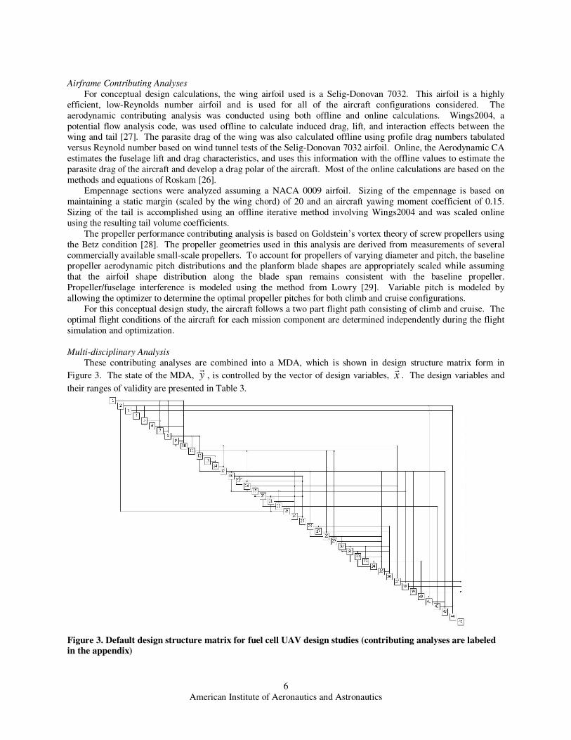
Multi-disciplinary Analysis
These contributing analyses are combined into a MDA, which is shown in design structure matrix form in
Figure 3. The state of the MDA, yr
, is controlled by the vector of design variables, xr
. The design variables and
their ranges of validity are presented in Table 3.
Figure 3. Default design structure matrix for fuel cell UAV design studies (contributing analyses are labeled in the appendix)
American Institute of Aeronautics and Astronautics
7
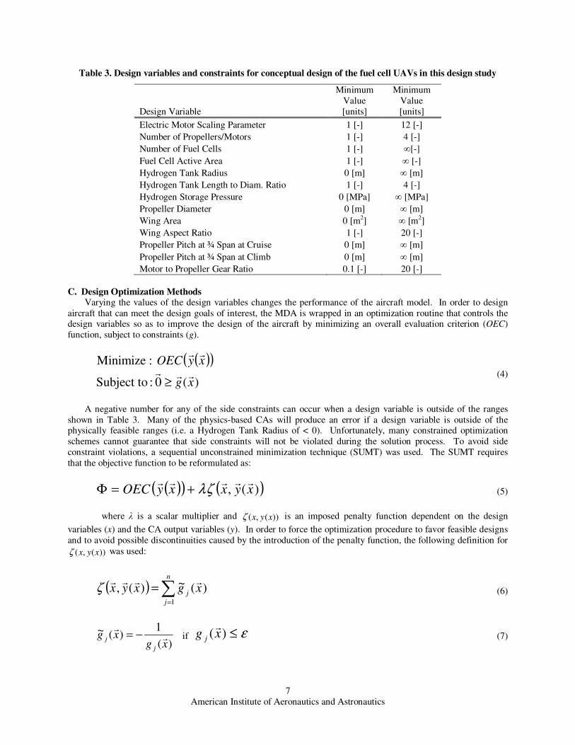
Table 3. Design variables and constraints for conceptual design of the fuel cell UAVs in this design study
Design Variable
Minimum
Value
[units]
Minimum
Value
[units]
Electric Motor Scaling Parameter 1 [-] 12 [-]
Number of Propellers/Motors 1 [-] 4 [-]
Number of Fuel Cells 1 [-] ∞[-]
Fuel Cell Active Area 1 [-] ∞ [-]
Hydrogen Tank Radius 0 [m] ∞ [m]
Hydrogen Tank Length to Diam. Ratio 1 [-] 4 [-]
Hydrogen Storage Pressure 0 [MPa] ∞ [MPa]
Propeller Diameter 0 [m] ∞ [m]
Wing Area 0 [m2] ∞ [m2]
Wing Aspect Ratio 1 [-] 20 [-]
Propeller Pitch at ¾ Span at Cruise 0 [m] ∞ [m]
Propeller Pitch at ¾ Span at Climb 0 [m] ∞ [m]
Motor to Propeller Gear Ratio 0.1 [-] 20 [-]
C. Design Optimization Methods Varying the values of the design variables changes the performance of the aircraft model. In order to design
aircraft that can meet the design goals of interest, the MDA is wrapped in an optimization routine that controls the design variables so as to improve the design of the aircraft by minimizing an overall evaluation criterion (OEC)
function, subject to constraints (g).
( )( )
)(0: Subject to
:Minimize
xg
xyOECrrr
rr
≥ (4)
A negative number for any of the side constraints can occur when a design variable is outside of the ranges
shown in Table 3. Many of the physics-based CAs will produce an error if a design variable is outside of the physically feasible ranges (i.e. a Hydrogen Tank Radius of < 0). Unfortunately, many constrained optimization
schemes cannot guarantee that side constraints will not be violated during the solution process. To avoid side
constraint violations, a sequential unconstrained minimization technique (SUMT) was used. The SUMT requires
that the objective function to be reformulated as:
( )( ) ( ))(, xyxxyOECrrrrr
λζ+=Φ (5)
where λ is a scalar multiplier and ))(,( xyxζ is an imposed penalty function dependent on the design
variables (x) and the CA output variables (y). In order to force the optimization procedure to favor feasible designs
and to avoid possible discontinuities caused by the introduction of the penalty function, the following definition for
))(,( xyxζ was used:
( ) ∑=
=n
j
jxgxyx
1
)(~)(,rrrr
ζ (6)
)(
1)(~
xgxg
j
j rr
−= if ε≤)(xg j
r (7)
American Institute of Aeronautics and Astronautics
8
2
)(2)(~
ε
ε xgxg
j
j
rr −
−= if ε>)(xgj
r (8)
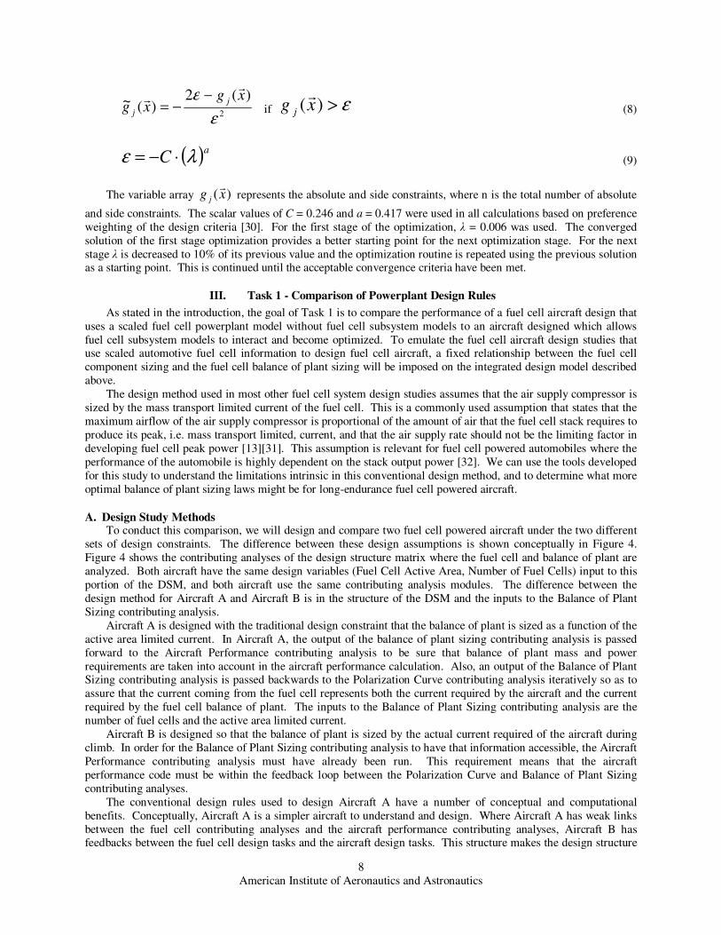
( )aC λε ⋅−= (9)
The variable array )(xg j
r represents the absolute and side constraints, where n is the total number of absolute
and side constraints. The scalar values of C = 0.246 and a = 0.417 were used in all calculations based on preference
weighting of the design criteria [30]. For the first stage of the optimization, λ = 0.006 was used. The converged
solution of the first stage optimization provides a better starting point for the next optimization stage. For the next
stage λ is decreased to 10% of its previous value and the optimization routine is repeated using the previous solution as a starting point. This is continued until the acceptable convergence criteria have been met.
III. Task 1 - Comparison of Powerplant Design Rules
As stated in the introduction, the goal of Task 1 is to compare the performance of a fuel cell aircraft design that
uses a scaled fuel cell powerplant model without fuel cell subsystem models to an aircraft designed which allows
fuel cell subsystem models to interact and become optimized. To emulate the fuel cell aircraft design studies that use scaled automotive fuel cell information to design fuel cell aircraft, a fixed relationship between the fuel cell
component sizing and the fuel cell balance of plant sizing will be imposed on the integrated design model described
above.
The design method used in most other fuel cell system design studies assumes that the air supply compressor is
sized by the mass transport limited current of the fuel cell. This is a commonly used assumption that states that the
maximum airflow of the air supply compressor is proportional of the amount of air that the fuel cell stack requires to
produce its peak, i.e. mass transport limited, current, and that the air supply rate should not be the limiting factor in
developing fuel cell peak power [13][31]. This assumption is relevant for fuel cell powered automobiles where the
performance of the automobile is highly dependent on the stack output power [32]. We can use the tools developed
for this study to understand the limitations intrinsic in this conventional design method, and to determine what more
optimal balance of plant sizing laws might be for long-endurance fuel cell powered aircraft.
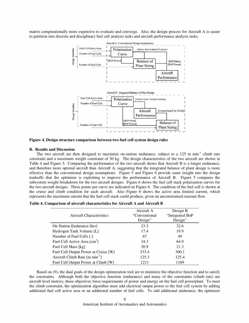
A. Design Study Methods To conduct this comparison, we will design and compare two fuel cell powered aircraft under the two different
sets of design constraints. The difference between these design assumptions is shown conceptually in Figure 4.
Figure 4 shows the contributing analyses of the design structure matrix where the fuel cell and balance of plant are
analyzed. Both aircraft have the same design variables (Fuel Cell Active Area, Number of Fuel Cells) input to this
portion of the DSM, and both aircraft use the same contributing analysis modules. The difference between the
design method for Aircraft A and Aircraft B is in the structure of the DSM and the inputs to the Balance of Plant
Sizing contributing analysis.
Aircraft A is designed with the traditional design constraint that the balance of plant is sized as a function of the
active area limited current. In Aircraft A, the output of the balance of plant sizing contributing analysis is passed
forward to the Aircraft Performance contributing analysis to be sure that balance of plant mass and power
requirements are taken into account in the aircraft performance calculation. Also, an output of the Balance of Plant Sizing contributing analysis is passed backwards to the Polarization Curve contributing analysis iteratively so as to
assure that the current coming from the fuel cell represents both the current required by the aircraft and the current
required by the fuel cell balance of plant. The inputs to the Balance of Plant Sizing contributing analysis are the
number of fuel cells and the active area limited current.
Aircraft B is designed so that the balance of plant is sized by the actual current required of the aircraft during
climb. In order for the Balance of Plant Sizing contributing analysis to have that information accessible, the Aircraft
Performance contributing analysis must have already been run. This requirement means that the aircraft
performance code must be within the feedback loop between the Polarization Curve and Balance of Plant Sizing
contributing analyses.
The conventional design rules used to design Aircraft A have a number of conceptual and computational
benefits. Conceptually, Aircraft A is a simpler aircraft to understand and design. Where Aircraft A has weak links
between the fuel cell contributing analyses and the aircraft performance contributing analyses, Aircraft B has feedbacks between the fuel cell design tasks and the aircraft design tasks. This structure makes the design structure
American Institute of Aeronautics and Astronautics
9
matrix computationally more expensive to evaluate and converge. Also, the design process for Aircraft A is easier
to partition into discrete and disciplinary fuel cell analysis tasks and aircraft performance analysis tasks.
Figure 4. Design structure comparison between two fuel cell system design rules
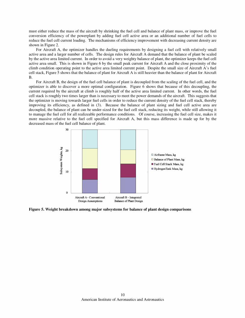
B. Results and Discussion The two aircraft are then designed to maximize on-station endurance, subject to a 125 m min-1 climb rate
constraint and a maximum weight constraint of 30 kg. The design characteristics of the two aircraft are shown in
Table 4 and Figure 5. Comparing the performance of the two aircraft shows that Aircraft B is a longer endurance,
and therefore more optimal aircraft than Aircraft A, suggesting that the integrated balance of plant design is more
effective than the conventional design assumptions. Figure 5 and Figure 6 provide some insight into the design
tradeoffs that the optimizer is exploiting to improve the performance of Aircraft B. Figure 5 compares the
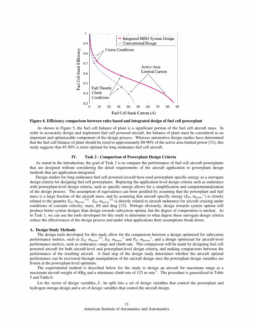
subsystem weight breakdown for the two aircraft designs. Figure 6 shows the fuel cell stack polarization curves for
the two aircraft designs. Three points per curve are indicated on Figure 6. The condition of the fuel cell is shown at
the cruise and climb condition for each aircraft. Also Figure 6 shows the active area limited current, which
represents the maximum current that the fuel cell stack could produce, given an unconstrained reactant flow.
Table 4. Comparison of aircraft characteristics for Aircraft A and Aircraft B
Aircraft Characteristics
Aircraft A
“Conventional
Design”
Design B
“Integrated BoP
Design”
On Station Endurance [hrs] 23.3 32.6
Hydrogen Tank Volume [L] 17.4 19.9
Number of Fuel Cells [-] 67 49
Fuel Cell Active Area [cm2] 34.3 64.9
Fuel Cell Mass [kg] 20.9 21.3
Fuel Cell Output Power at Cruise [W] 333.4 300.1
Aircraft Climb Rate [m min-1] 125.3 125.4
Fuel Cell Output Power at Climb [W] 1211 1189
Based on (9), the dual goals of the design optimization tool are to minimize the objective function and to satisfy
the constraints. Although both the objective function (endurance) and many of the constraints (climb rate) are
aircraft level metrics, these objectives force requirements of power and energy on the fuel cell powerplant. To meet
the climb constraint, the optimization algorithm must add electrical output power to the fuel cell system by adding
additional fuel cell active area or an additional number of fuel cells. To add additional endurance, the optimizer
American Institute of Aeronautics and Astronautics
10
must either reduce the mass of the aircraft by shrinking the fuel cell and balance of plant mass, or improve the fuel
conversion efficiency of the powerplant by adding fuel cell active area or an additional number of fuel cells to
reduce the fuel cell current loading. The mechanisms of efficiency improvement with decreasing current density are
shown in Figure 2.
For Aircraft A, the optimizer handles the dueling requirements by designing a fuel cell with relatively small
active area and a larger number of cells. The design rules for Aircraft A demand that the balance of plant be scaled by the active area limited current. In order to avoid a very weighty balance of plant, the optimizer keeps the fuel cell
active area small. This is shown in Figure 6 by the small peak current for Aircraft A and the close proximity of the
climb condition operating point to the active area limited current point. Despite the small size of Aircraft A’s fuel
cell stack, Figure 5 shows that the balance of plant for Aircraft A is still heavier than the balance of plant for Aircraft
B.
For Aircraft B, the design of the fuel cell balance of plant is decoupled from the scaling of the fuel cell, and the
optimizer is able to discover a more optimal configuration. Figure 6 shows that because of this decoupling, the
current required by the aircraft at climb is roughly half of the active area limited current. In other words, the fuel
cell stack is roughly two times larger than is necessary to meet the power demands of the aircraft. This suggests that
the optimizer is moving towards larger fuel cells in order to reduce the current density of the fuel cell stack, thereby
improving its efficiency, as defined in (3). Because the balance of plant sizing and fuel cell active area are
decoupled, the balance of plant can be under-sized for the fuel cell stack, reducing its weight, while still allowing it to manage the fuel cell for all realizeable performance conditions. Of course, increasing the fuel cell size, makes it
more massive relative to the fuel cell specified for Aircraft A, but this mass difference is made up for by the
decreased mass of the fuel cell balance of plant.
Figure 5. Weight breakdown among major subsystems for balance of plant design comparisons
American Institute of Aeronautics and Astronautics
11
Figure 6. Efficiency comparison between rules based and integrated design of fuel cell powerplant
As shown in Figure 5, the fuel cell balance of plant is a significant portion of the fuel cell aircraft mass. In
order to accurately design and implement fuel cell powered aircraft, the balance of plant must be considered as an
important and optimizeable component of the design process. Whereas automotive design studies have determined
that the fuel cell balance of plant should be sized to approximately 80-90% of the active area limited power [31], this
study suggests that 45-50% is more optimal for long endurance fuel cell aircraft.
IV. Task 2 - Comparison of Powerplant Design Criteria
As stated in the introduction, the goal of Task 2 is to compare the performance of fuel cell aircraft powerplants
that are designed without considering the detail requirements of the aircraft application to powerplant design
methods that are application-integrated.
Design studies for long endurance fuel cell powered aircraft have used powerplant specific energy as a surrogate
design criteria for designing fuel cell powerplants. Replacing the application-level design criteria such as endurance
with powerplant-level design criteria, such as specific energy allows for a simplification and compartmentalization
of the design process. The assumption of equivalence can been justified by assuming that the powerplant and fuel
mass is a large fraction of the aircraft mass, and by assuming that aircraft specific energy (EFC mpower-1) is closely
related to the quantity EFC mpower-3/2. EFC mpower
-3/2 is directly related to aircraft endurance for aircraft cruising under conditions of constant velocity, mass, lift and drag [33]. Perhaps obviously, design towards system optima will
produce better system designs than design towards subsystem optima, but the degree of compromise is unclear. As
in Task 1, we can use the tools developed for this study to determine to what degree these surrogate design criteria
reduce the effectiveness of the design process and under what applications their assumptions break down.
A. Design Study Methods The design tools developed for this study allow for the comparison between a design optimized for subsystem
performance metrics, such as EFC mpower-3/2, EFC mpower
-1 and PFC mpower-1, and a design optimized for aircraft-level
performance metrics, such as endurance, range and climb rate. This comparison will be made by designing fuel cell
powered aircraft for both aircraft-level and powerplant-level design criteria, and making comparisons between the
performance of the resulting aircraft. A final step of the design study determines whether the aircraft optimal
performance can be recovered through manipulation of the aircraft design once the powerplant design variables are frozen at the powerplant-level optimum.
The experimental method is described below for the study to design an aircraft for maximum range at a
maximum aircraft weight of 40kg and a minimum climb rate of 125 m min-1. The procedure is generalized in Table
5 and Table 6.
Let the vector of design variables, xr
, be split into a set of design variables that control the powerplant and
hydrogen storage design and a set of design variables that control the aircraft design.
American Institute of Aeronautics and Astronautics
12
[ ] TT
airframe
T
power xxxrrr
:= (10)
[ ] PARrAnx HHFCcells
T
power 2tank2=r
(11)
[ ] climbcruise RppSdYXx wmotormotor
T
airframe =r
(12)
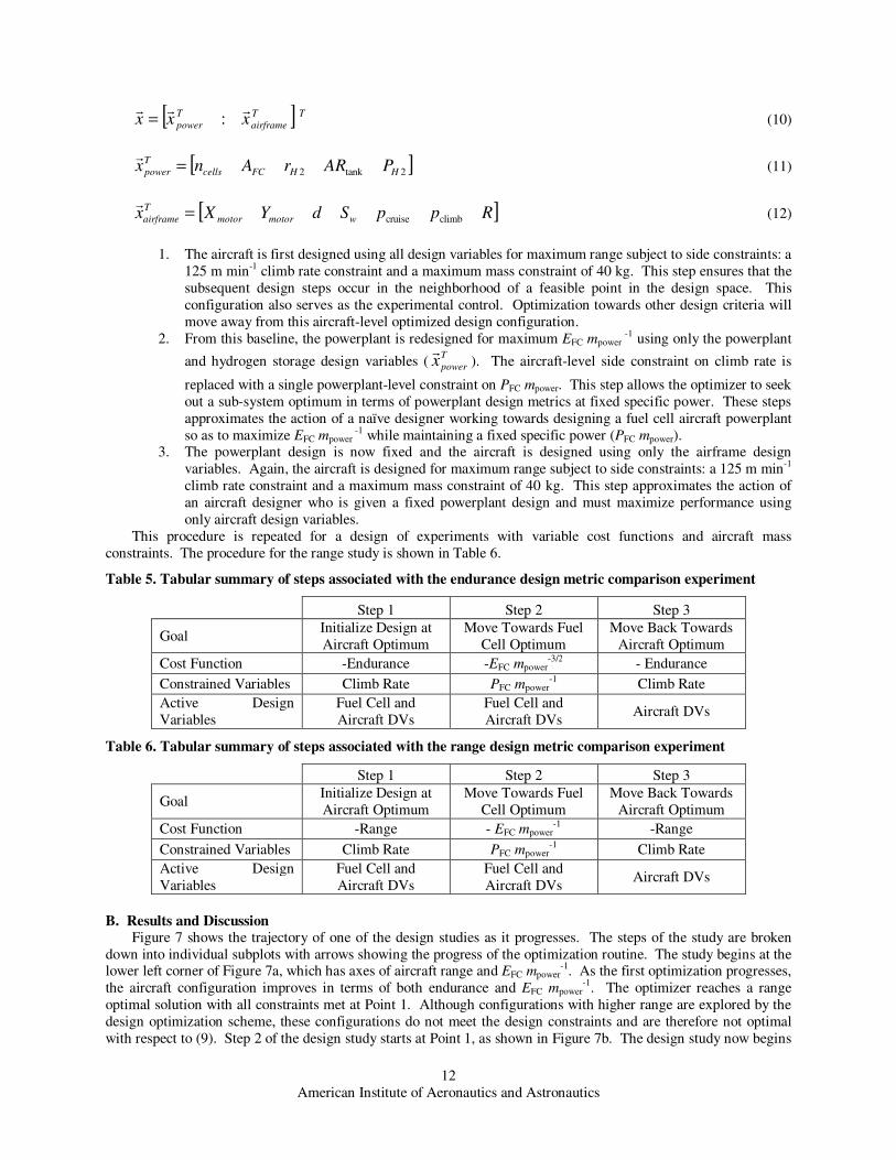
1. The aircraft is first designed using all design variables for maximum range subject to side constraints: a
125 m min-1 climb rate constraint and a maximum mass constraint of 40 kg. This step ensures that the
subsequent design steps occur in the neighborhood of a feasible point in the design space. This
configuration also serves as the experimental control. Optimization towards other design criteria will
move away from this aircraft-level optimized design configuration.
2. From this baseline, the powerplant is redesigned for maximum EFC mpower -1 using only the powerplant
and hydrogen storage design variables (T
powerxr
). The aircraft-level side constraint on climb rate is
replaced with a single powerplant-level constraint on PFC mpower. This step allows the optimizer to seek
out a sub-system optimum in terms of powerplant design metrics at fixed specific power. These steps
approximates the action of a naïve designer working towards designing a fuel cell aircraft powerplant
so as to maximize EFC mpower -1 while maintaining a fixed specific power (PFC mpower).
3. The powerplant design is now fixed and the aircraft is designed using only the airframe design
variables. Again, the aircraft is designed for maximum range subject to side constraints: a 125 m min-1
climb rate constraint and a maximum mass constraint of 40 kg. This step approximates the action of
an aircraft designer who is given a fixed powerplant design and must maximize performance using
only aircraft design variables.
This procedure is repeated for a design of experiments with variable cost functions and aircraft mass
constraints. The procedure for the range study is shown in Table 6.
Table 5. Tabular summary of steps associated with the endurance design metric comparison experiment
Step 1 Step 2 Step 3
Goal Initialize Design at
Aircraft Optimum
Move Towards Fuel
Cell Optimum
Move Back Towards
Aircraft Optimum
Cost Function -Endurance -EFC mpower-3/2 - Endurance
Constrained Variables Climb Rate PFC mpower-1 Climb Rate
Active Design
Variables
Fuel Cell and
Aircraft DVs
Fuel Cell and
Aircraft DVs Aircraft DVs
Table 6. Tabular summary of steps associated with the range design metric comparison experiment
Step 1 Step 2 Step 3
Goal Initialize Design at
Aircraft Optimum
Move Towards Fuel
Cell Optimum
Move Back Towards
Aircraft Optimum
Cost Function -Range - EFC mpower-1 -Range
Constrained Variables Climb Rate PFC mpower-1 Climb Rate
Active Design
Variables
Fuel Cell and
Aircraft DVs
Fuel Cell and
Aircraft DVs Aircraft DVs
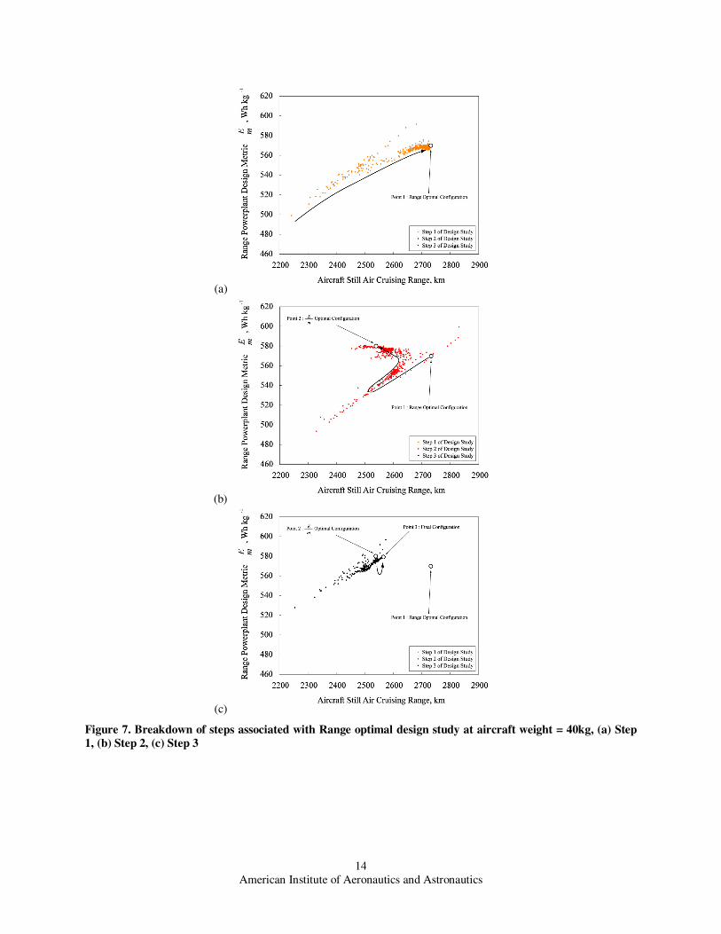
B. Results and Discussion Figure 7 shows the trajectory of one of the design studies as it progresses. The steps of the study are broken
down into individual subplots with arrows showing the progress of the optimization routine. The study begins at the lower left corner of Figure 7a, which has axes of aircraft range and EFC mpower
-1. As the first optimization progresses,
the aircraft configuration improves in terms of both endurance and EFC mpower-1. The optimizer reaches a range
optimal solution with all constraints met at Point 1. Although configurations with higher range are explored by the
design optimization scheme, these configurations do not meet the design constraints and are therefore not optimal
with respect to (9). Step 2 of the design study starts at Point 1, as shown in Figure 7b. The design study now begins
American Institute of Aeronautics and Astronautics
13
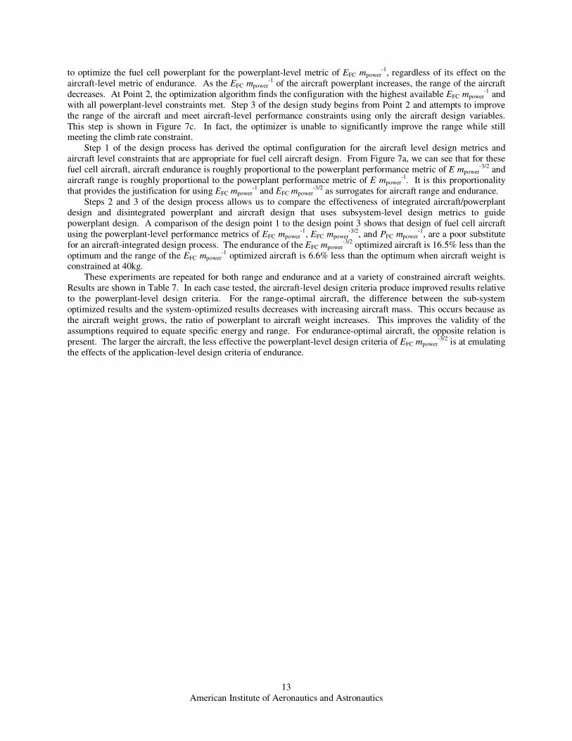
to optimize the fuel cell powerplant for the powerplant-level metric of EFC mpower-1, regardless of its effect on the
aircraft-level metric of endurance. As the EFC mpower-1 of the aircraft powerplant increases, the range of the aircraft
decreases. At Point 2, the optimization algorithm finds the configuration with the highest available EFC mpower-1 and
with all powerplant-level constraints met. Step 3 of the design study begins from Point 2 and attempts to improve
the range of the aircraft and meet aircraft-level performance constraints using only the aircraft design variables.
This step is shown in Figure 7c. In fact, the optimizer is unable to significantly improve the range while still meeting the climb rate constraint.
Step 1 of the design process has derived the optimal configuration for the aircraft level design metrics and
aircraft level constraints that are appropriate for fuel cell aircraft design. From Figure 7a, we can see that for these
fuel cell aircraft, aircraft endurance is roughly proportional to the powerplant performance metric of E mpower-3/2 and
aircraft range is roughly proportional to the powerplant performance metric of E mpower-1. It is this proportionality
that provides the justification for using EFC mpower-1 and EFC mpower
-3/2 as surrogates for aircraft range and endurance.
Steps 2 and 3 of the design process allows us to compare the effectiveness of integrated aircraft/powerplant
design and disintegrated powerplant and aircraft design that uses subsystem-level design metrics to guide
powerplant design. A comparison of the design point 1 to the design point 3 shows that design of fuel cell aircraft
using the powerplant-level performance metrics of EFC mpower-1, EFC mpower
-3/2, and PFC mpower-1, are a poor substitute
for an aircraft-integrated design process. The endurance of the EFC mpower-3/2 optimized aircraft is 16.5% less than the
optimum and the range of the EFC mpower-1 optimized aircraft is 6.6% less than the optimum when aircraft weight is
constrained at 40kg.
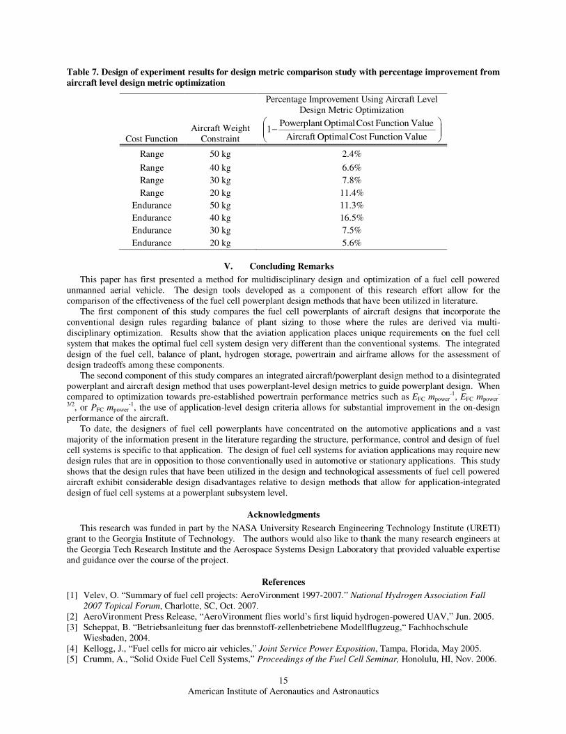
These experiments are repeated for both range and endurance and at a variety of constrained aircraft weights.
Results are shown in Table 7. In each case tested, the aircraft-level design criteria produce improved results relative
to the powerplant-level design criteria. For the range-optimal aircraft, the difference between the sub-system
optimized results and the system-optimized results decreases with increasing aircraft mass. This occurs because as
the aircraft weight grows, the ratio of powerplant to aircraft weight increases. This improves the validity of the
assumptions required to equate specific energy and range. For endurance-optimal aircraft, the opposite relation is
present. The larger the aircraft, the less effective the powerplant-level design criteria of EFC mpower-3/2 is at emulating
the effects of the application-level design criteria of endurance.
American Institute of Aeronautics and Astronautics
14
(a)
(b)
(c)
Figure 7. Breakdown of steps associated with Range optimal design study at aircraft weight = 40kg, (a) Step
1, (b) Step 2, (c) Step 3
American Institute of Aeronautics and Astronautics
15
Table 7. Design of experiment results for design metric comparison study with percentage improvement from
aircraft level design metric optimization
Cost Function
Aircraft Weight
Constraint
Percentage Improvement Using Aircraft Level
Design Metric Optimization
−
ValueFunction Cost OptimalAircraft
ValueFunction Cost Optimal Powerplant1
Range 50 kg 2.4%
Range 40 kg 6.6%
Range 30 kg 7.8%
Range 20 kg 11.4%
Endurance 50 kg 11.3%
Endurance 40 kg 16.5%
Endurance 30 kg 7.5%
Endurance 20 kg 5.6%
V. Concluding Remarks
This paper has first presented a method for multidisciplinary design and optimization of a fuel cell powered
unmanned aerial vehicle. The design tools developed as a component of this research effort allow for the
comparison of the effectiveness of the fuel cell powerplant design methods that have been utilized in literature.
The first component of this study compares the fuel cell powerplants of aircraft designs that incorporate the
conventional design rules regarding balance of plant sizing to those where the rules are derived via multi-
disciplinary optimization. Results show that the aviation application places unique requirements on the fuel cell
system that makes the optimal fuel cell system design very different than the conventional systems. The integrated
design of the fuel cell, balance of plant, hydrogen storage, powertrain and airframe allows for the assessment of
design tradeoffs among these components.
The second component of this study compares an integrated aircraft/powerplant design method to a disintegrated powerplant and aircraft design method that uses powerplant-level design metrics to guide powerplant design. When
compared to optimization towards pre-established powertrain performance metrics such as EFC mpower-1, EFC mpower
-
3/2, or PFC mpower-1, the use of application-level design criteria allows for substantial improvement in the on-design
performance of the aircraft.
To date, the designers of fuel cell powerplants have concentrated on the automotive applications and a vast
majority of the information present in the literature regarding the structure, performance, control and design of fuel
cell systems is specific to that application. The design of fuel cell systems for aviation applications may require new
design rules that are in opposition to those conventionally used in automotive or stationary applications. This study
shows that the design rules that have been utilized in the design and technological assessments of fuel cell powered
aircraft exhibit considerable design disadvantages relative to design methods that allow for application-integrated
design of fuel cell systems at a powerplant subsystem level.
Acknowledgments
This research was funded in part by the NASA University Research Engineering Technology Institute (URETI)
grant to the Georgia Institute of Technology. The authors would also like to thank the many research engineers at
the Georgia Tech Research Institute and the Aerospace Systems Design Laboratory that provided valuable expertise
and guidance over the course of the project.
References
[1] Velev, O. “Summary of fuel cell projects: AeroVironment 1997-2007.” National Hydrogen Association Fall
2007 Topical Forum, Charlotte, SC, Oct. 2007.
[2] AeroVironment Press Release, “AeroVironment flies world’s first liquid hydrogen-powered UAV,” Jun. 2005.
[3] Scheppat, B. “Betriebsanleitung fuer das brennstoff-zellenbetriebene Modellflugzeug,“ Fachhochschule
Wiesbaden, 2004.
[4] Kellogg, J., “Fuel cells for micro air vehicles,” Joint Service Power Exposition, Tampa, Florida, May 2005. [5] Crumm, A., “Solid Oxide Fuel Cell Systems,” Proceedings of the Fuel Cell Seminar, Honolulu, HI, Nov. 2006.

American Institute of Aeronautics and Astronautics
16
[6] Bradley, T.H., Moffitt, B., Mavris, D., and Parekh, D.E., “Development and Experimental Characterization of a
Fuel Cell Powered Aircraft,” Journal of Power Sources, Vol. 171, 2007, pp. 793-801.
[7] California State University Press Release, “Cal State L.A.'s fuel-cell plane passes key flight test,” Sep. 2006.
[8] Deutsches Zentrum fuer Luft- und Raumfahrt Press Release, “Erfolgreicher erstflug des Hyfish,” April 3, 2007.
[9] Herwerth, C., Chiang, C., Ko, A., Matsuyama, S., Choi, SB., Mirmirani, M., Gamble, D., Arena, A., Koschany
A., Gu, G., and Wankewycz, T., “Development of a Small Long Endurance Hybrid PEM Fuel Cell Powered UAV,” Society of Automotive Engineers Paper 2007-01-3930, Sep. 2007.
[10] Kwon, S., ”PEM fuel cell system for UAV,” Available online at http://rocket.kaist.ac.kr/03_sub_08.htm
[11] “AeroVironment's unmanned aircraft achieves record flight,” Fuel Cells Bulletin, Vol. 2007, No. 8, 2007, p. 8.
[12] Friend, M.G., Daggett, D.L., “Fuel cell demonstrator airplane,” AIAA Paper 2003-2868, Jul. 2003.
[13] Kohout, L.L., Schmitz, P.C., “Fuel cell proplulsion systems for an all-electric personal air vehicle.” AIAA
Paper 2003-2867, Jul. 2003.
[14] Baldock, N., and Mokhtarzadeh-Dehghan, M.R., “A study of solar-powered, high-altitude unmanned aerial
vehicles,” Aircraft Engineering and Aerospace Technology: An International Journal, Vol. 78, No. 3, 2006, pp.
187–193.
[15] Nickol, C.L., Guynn, M.D., Kohout, L.L., and Ozoroski, T.A., “High altitude long endurance air vehicle
analysis of alternatives and technology requirements development,” AIAA Paper 2007-1050, Jan. 2007.
[16] Burke, K.A. “Unitized regenerative fuel cell development,” NASA/TM-2003-212739, 2003. [17] Himansu, A., Freeh, J.E., Steffen, C.J., Tornabene, R.T., and Wang, X.-Y.J., “Hybrid solid oxide fuel cell/gas
turbine system design for high altitude long endurance aerospace missions,” NASA/TM-2006-214328, 2006.
[18] Moffitt, B.A., Bradley, T.H., Parekh, D.E., and Mavris, D.N., “Design space exploration of small-scale PEM
fuel cell unmanned aerial vehicle,” AIAA Paper 2006-7701, Sep. 2006
[19] Moffitt, B., Bradley, T.H., Mavris, D., and Parekh, D.E., “Reducing Design Error of a Fuel Cell UAV through
Variable Fidelity Optimization,” AIAA Paper 2007-7793, Sep. 2007.
[20] Colozza, A.J., “Hydrogen storage for aircraft applications overview,” NASA/CR—2002-211867, 2002.
[21] Lark, R.F., “Recent advances in lightweight, filament-wound composite pressure vessel technology,” Energy
Technology Conference, Houston, TX, Sept. 1977.
[22] Shigley, J., Mischke, C. and Budynas, R. Mechanical Engineering Design. 7th Edition, McGraw-Hill, New
York. [23] Kulkarni, S.V., and Zweben, C.H., Composites in pressure vessels and piping. American Society of Mechanical
Engineers, New York, 1977.
[24] Harris, J., Grande, R. and Higgins, M., “Ultralight propellant tank for NASA space technology 5,” AIAA Paper
2003-4608, Jul. 2003.
[25] W. L. Gore & Associates, Inc. “Gore Primea 58 Series Membranes,” Product Literature, 2003.
[26] Roskam, J., Airplane Design Part VI: Preliminary Calculation of Aerodynamic, Thrust and Power
Characteristics, DAR Corporation, Lawrence, Kansas, 2000.
[27] Phillips, W.F., and Snyder, D.O., “Modern adaptation of Prandtl’s classic lifting-line theory,” Journal of
Aircraft, Vol. 37, No. 4, 2000, pp. 662-670.
[28] Goldstein, S., “On the Vortex Theory of Screw Propellers,” Proceedings of the Royal Society of London, Series
A. Vol. 123, No. 792, pp. 440-495, 1929.
[29] Lowry, J. T., Performance of Light Aircraft, AIAA Education Series, Reston, Virginia, 1999. [30] Vanderplaats, G.N., Numerical Optimization Techniques for Engineering Design, McGraw Hill, New York,
1984.
[31] Gelfi, S., Stefanopoulou A.G., Pukrushpan, J.T. and Peng, H., “Dynamics of low-pressure and high-pressure
fuel cell air supply systems,” American Control Conference, Denver CO, Jun. 2003. pp 2049-2054.
[32] Kim, M.-J., and Peng, H., “Power management and design optimization of fuel cell/battery hybrid vehicles,”
Journal of Power Sources Vol. 165, 2007, pp. 819-32.
[33] Phillips, W.F., Mechanics of Flight, John Wiley and Sons, Inc., Hoboken, New Jersey, 2004.