
DESIGN STANDARDS Section VII. Materials & Installation ...
40
DESIGN STANDARDS Section VII. Materials & Installation Policies (Revised July 31, 2009) Yale University Facilities Planning & Construction
Transcript of DESIGN STANDARDS Section VII. Materials & Installation ...
DESIGN STANDARDS
Section VII. Materials & Installation Policies
(Revised July 31, 2009)
Yale University Facilities Planning & Construction

2
Division VII Materials & Installation Policies Index
MATERIALS & INSTALLATION POLICIES
DEIONIZED WATER AT LABORATORIES (CHANGE #14 9/1/2005)
POLICY FOR SMOKE DETECTORS AT LABORATORIES (CHANGE # 8 9/1/2005)
ATTIC STOCK
GENERIC LABORATORY FEATURES (CHANGE # 10 9/1/2005)
SPACE STANDARDS(REVISED 8/06)
LABORATORY ACCESSIBILITY STANDARDS
FURNITURE STANDARDS
CORRIDOR FINISH TREATMENTS (CHANGE # 42, 5/20/09, CHANGE #43, 6/15/09)
XOMAT POLICY
BIOLOGICAL SAFETY CABINET INSTALLATION
REQUIRED PHYSICAL ACCESS POLICY (CHANGE #47, 7/31/09)
AIR HANDLING SYSTEMS POLICY
IN SUPPORT OF SPECIFIC SPACE USES
OFFICES WITHIN
OFFICES
POLICY FOR THE APPLICATION OF DDC CONTROLS
APPLICATION OF DDC CONTROLS
SEIBE ENVIRONMENTAL CONTROLS
CONTROLS POLICY: OFF-HOURS SET BACK POLICY
DDC CONTROL APPLICATION POLICY
GLASS PIPE REMOVAL POLICY
LABORATORY AIR FLOW RATE
MC CABLE POLICY
AUTOCLAVE ROOM REQUIREMENTS
TELECOM POLICY
EMERGENCY POWER POLICY
LOW VOLTAGE SYSTEM STANDARDS
EXTERIOR LIGHTING CRITERIA
PEDESTRIAN LIGHTING
PARKING AREAS
HIGH PRESSURE SODIUM LIGHTING IS TO BE USED
REQUIREMENTS FOR REDUNDANCY AND STANDBY ELECTRIC POWER

3
VII. MATERIALS & INSTALLATION POLICIES
DEIONIZED WATER AT LABORATORIES (Change #14 9/1/2005) Provide 1 Deionized water for every 2 sinks. (If additional local processing is required, the department is responsible for providing it). Top of the Document
4
POLICY FOR SMOKE DETECTORS AT LABORATORIES (Change # 8 9/1/2005)
1. At Laboratories provide 1 central station smoke detector at egress door.
2. At Lab Support spaces provide 1 central station smoke detector in room.
3. Do not install heat detectors unless occupancy in normal use might produce vapors that would trigger
smoke detectors. Top of the Document
5
ATTIC STOCK No attic stock is to be specified in the Contract Documents. However, left over supplies of acoustic ceiling tile and vinyl composition tile are to be turned over to Yale at the end of the project. Top of the Document

6
GENERIC LABORATORY FEATURES (Change # 10 9/1/2005) The generic concept, as utilized at Yale School of Medicine, had its genesis in two types of construction and renovation projects. First, were the relatively small projects that, prior to the late 1980’s, were custom designed laboratories. These laboratories reflected the idiosyncrasies of the individual researcher as opposed to the research itself. When the space was reassigned another, often major, renovation was required to respect the idiosyncrasies of the newly assigned investigator. With relatively long reassignment and recycle times, renovation of laboratories for these reasons was not necessarily inappropriate. As cycle times reduced, the costs of these types of renovations became prohibitive. Second, the Boyer Center for Molecular Medicine (BCMM) was designed without assignments. This was consciously done in order to minimize some of the idiosyncratic responses but also to recognize that during the life of a project from inception to occupancy there might be changes in assignment. That building carried a very substantial retrofit component to modify the labs after assignment. The retrofit was done after the building was finished. In studying both of these, Facilities Planning instituted a program of generic design that would reflect the needs of wet bench scientists and allow for appropriate specificity within a fairly structured framework. Analyses were done of benchwork widths, aisle widths, equipment locations, and lighting relative to benches and electrical and gas utilities. A casework design was standardized using standard components that reflected the typical wet bench at the School. The result was a laboratory layout, use of materials, and designation of utilities with a high degree of predetermined specificity. Minor adjustments for location of knee spaces and size and type of drawer and door units provided virtually 99+% of the cases. This is in part due to the lack of chemistry laboratories. Cupsinks were eliminated both as a practical matter and as a request from the New Haven Water Authority and Sewer Authority. Since 1990 there have only been two statements of dissatisfaction. One of those was withdrawn once the logic was expressed. The concept has been used on every laboratory renovation since 1990 both in small one-room renovations to the recent major renovation of SHM B-Wing, First Floor. The concept, in particular with larger rather than smaller laboratory modules, allows for considerable flexibility in assignment without modification to the laboratories. The larger allocations of space for fixed equipment permits flexibility in changes based on the nature of the research and available technology. A recent modification allows for dedicated rooms for hot work to conform to NRC regulations while not inhibiting activities in the remainder of the lab. Top of the Document

7
The following lists the specific generic attributes. ROOM LAYOUT 1. Island benches shall be perpendicular to exterior wall with carrels at exterior wall. 2. The aisle between laboratory benches shall be 5’-0” wide. 3. Sinks shall be located on exterior/corridor wall, not on the bench, to allow for flexibility. Provide one sink per 8-10
workstations. 4. Separate rooms shall be provided if required for "hot" (i.e., radioactive) work. Provide one “hot sink” and one hand
washing sink. 5. Utility drop located at carrel/bench intersection. 6. Fume hoods shall be located away from exit door of lab and shall not be directly opposite carrels. 7. Light level of 70 foot candles minimum maintained at bench. 8. Fluorescent lights parallel to lab benches, centered on edge of benches. 9. No incandescent lighting. 10. New windows and existing refurbished windows shall be fixed. 11. Radiant ceiling panels at exterior walls. 12. Labs of greater than 1000 SF require two exit doors. 13. All corridor doors shall have magnetic hold opens if open doors are desired. 14. Corridor wall inside lab is the equipment wall. 15. Emergency gas shut-offs are to be provided within the lab, by the entry door, within the corridor demising wall. 16. Labs will be open in design. No subdivisions within laboratories by researcher. (Change # 10, 9/1/2005) BENCH & CARREL 1. Lab benches: Wood or metal casework acceptable. 2. Lab benches shall be 5’-0” wide. 3. No Unistrut shelving. 4. Grey epoxy counters and reagent shelving shall be provided. 5. One DI outlet provided per lab module connected to house system. 6. No cupsinks. 7. Knee spaces are provided for waste containers and refrigerators. 8. No task lighting at the benches. Task lighting provided at carrels. 9. Two phone/data drops per office and one per carrel, plus one wall phone per lab, in star pattern to data and
telephone closet. 10. Sinks to be stainless steel, not epoxy. 11. Carrel shall be 3’-6” wide minimum. 12. Bench plus carrel should equal 10’ linear feet. 13. One hand-held, deck mounted, eyewash/shower at all non-radioactive sinks. FINISHES/SERVICES TO LAB
1. Air, gas, vacuum provided at all benches as required. Gas and air outlets shall be minimized- dependent on
particular needs. 2. AGV turrets are the double height type (i.e. two outlets per service, per location). 3. Duplex outlets spacing – 18” OC at lab bench, 24” OC at equipment wall. 4. Ceiling tiles are to be 2 x 2 or 2 x 4 lay-in tile, Yale University standard tiles. 5. No exposed ceilings due to maintenance cost premium. 6. VCT flooring in laboratories and corridors. (Standard colors required in corridors.)
Please note: for future flexibility (bench reconfiguration/removal), VCT in laboratories shall not be laid out using bench locations to frame floor patterns, rather the lab flooring shall be a continuous, undifferentiated pattern unrelated to bench locations. In addition, VCT shall be continuous under all casework.
OTHER 1. Waste stream management (inbound boxes; outgoing containers) stored in closets, in corridors, or autoclave
room. Top of the Document

8
SPACE STANDARDS (Revised 8/06)
APPROXIMATE OFFICE NASF OCCUPANT TYPE A 250 Department Chair* B 180 Section Chief
C 150 Director D 120 Faculty E 110 Associate Director D 100 Manager
CUBICLES 64 Typical (may vary up or down) * 250 sf is the average. 280 is the absolute maximum if physical circumstances require Top of the Document

9
LABORATORY ACCESSIBILITY STANDARDS Yale School of Medicine has received a Handicap Waiver from the provisions of Section 1108.12, Laboratory Stations of the BOCA National Building Code/1996 portion of the 1999 State Building Code. using the alternative described in the pages that follow. This waiver was approved by the State of Connecticut Office of Protection and Advocacy for Persons with Disabilities and the Department of Public Safety, Division of Fire, Emergency & Building Services, Office of the State Building Inspector with support from the New Haven Office of Building Inspection & Enforcement. The alternative described in the following pages allows for an adaptable approach to meet the needs of a person with a physical disability in laboratories. It is key that all adaptable elements of the lab workstation be identified and labeled clearly on the construction documents for compliance with the waiver. Top of the Document

10
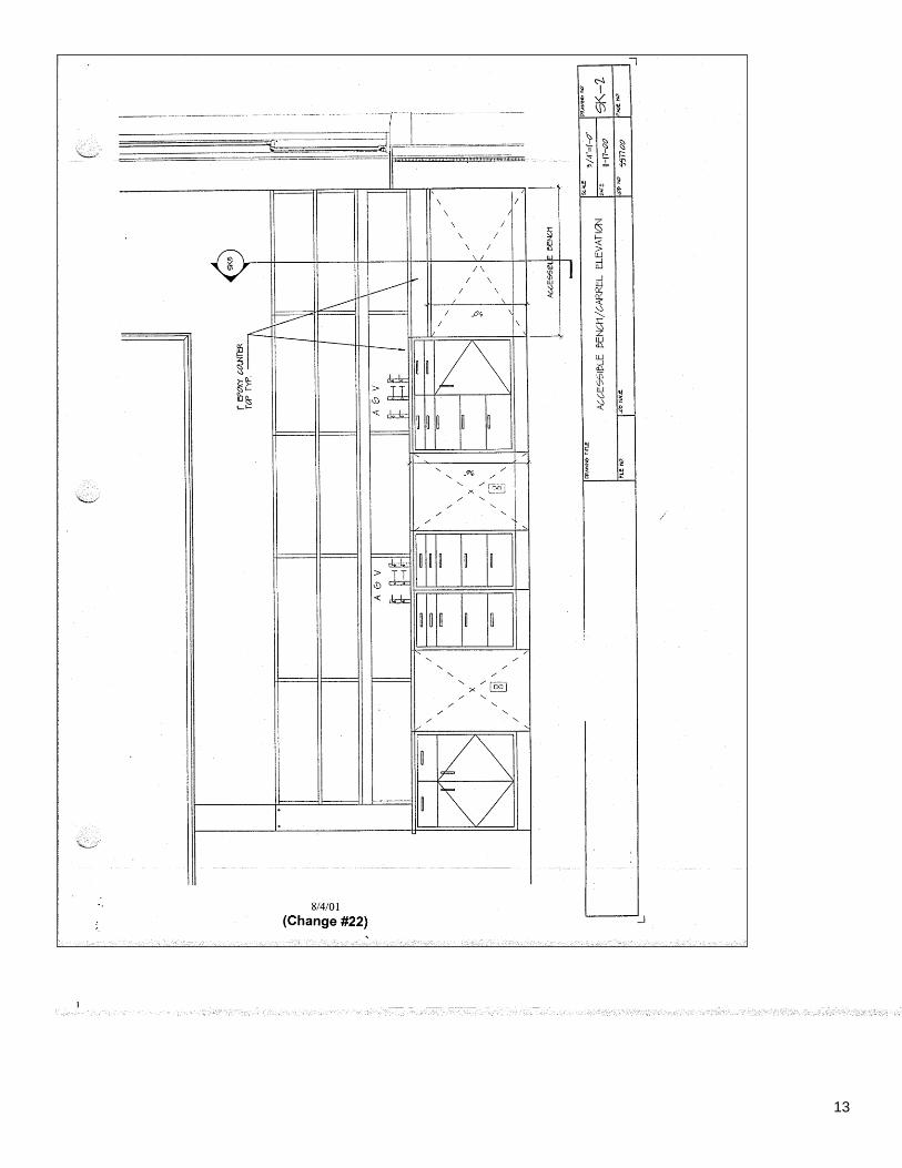
Suggestions for an Adaptable Approach to Laboratory Accessibility
November 22, 2000 Please note that a workstation can include 1) four to six linear feet of laboratory bench (including bench utilities), 2) a carrel, 3) access to a sink and, in some cases only, 4) access to a fume hood. The requirement for accessibility in both the current and former code is the provision of required accessibility per Lab Group (see attached for full definition of Lab Group). 1. To provide accessibility at the laboratory bench, the carrel would become the laboratory bench for the person with a physical disability. When the carrel is part of the bench it is provided with a chemical resistant laminate top. Alternatively, when the carrel is not part of the bench, an area of bench countertop would be provided with a seam to allow for easy removal of an area of countertop. Alternate heights can be provided by simply exchanging different height casework that supports the countertop. In this way an appropriate height bench space would easily be installed in the event a person with a physical disability is employed in the lab. 2. To provide accessibility at the carrel an additional carrel would be assigned to a person with a physical disability. Alternatively, when a carrel is not available an area of bench countertop with a seam will be provided to allow for easy removal of an area of countertop. An alternate height can be provided for a carrel by simply exchanging different height casework that supports the countertop. In this way an appropriate height carrel would be installed in the event a person with a physical disability is employed in the lab. 3. To provide accessibility at the laboratory sink we propose the provision of an area of bench countertop adjacent to the sink with a seam to allow for easy removal of an area of countertop. Alternate heights can be provided by simply exchanging different height casework that supports the countertop. In this way we would install an appropriate height hand-washing sink in the event a person with a physical disability is employed in the lab. The adjacency of the seamed countertop (and future location of the accessible sink) to the existing sink would allow for easy tie-ins to the existing piping. This arrangement would work when the sink is located at the end of a bench or when it is located against a wall. (Condition 1 and 2 in SK-1) 4. To provide accessibility at the fume hood we propose that an area be designated within the laboratories of a particular Lab Group for the location of a future accessible fume hood to be installed in the event that a person with a physical disability is employed in the laboratory. Alternatively, if an area is not designated an existing fume hood could easily be changed out to an accessible fume hood in the event a person with a physical disability is employed in the lab. (See SK 1, SK-2, SK-3, SK-4, SK-5) f:\pm&c\capital\projects\bldgcodes\lab stations - ada1.doc
Top of the Document
11
Yale University Central Campus and School of Medicine
Lab Group Definition
At the Central Campus (includes Science Hill) and at the School of Medicine, the organizational unit of research is the academic department or section. Each department or section consists of a group of faculty members who are carrying out research within a thematically related area. At the Central Campus (includes science Hill) departments include areas such as chemistry, biology or physics. At the School of Medicine departments include areas related to basic biomedical science (e.g., genetics, cell biology, physiology) or clinical science (e.g., dermatology, neurology, orthopedic surgery). The Chair of the department, or the Chief of the section, has responsibility for the implementation of Central Campus (includes Science Hill) or Medical School policies. He/she also has authority for the assignment of space and other resources. Thus, the faculty and staff of each department or section function as an interdependent laboratory group, who work together and share both equipment and facilities. It should be noted that in the renovation of laboratories in existing buildings, the relationship of the renovated laboratory to the laboratory group and the constraints of the existing building configuration should be considered in defining accessibility requirements. Top of the Document

12
13

14
Top of the Document

15
Top of the Document

16
Top of the Document

17
YALE UNIVERISTY FURNITURE STANDARDS
(equivalent product and finish level from other Yale University approved vendors is acceptable with prior approval of Project Manager)
Revised 4/15/04 (Change # 1, 7/1/04) Private Office
Quantity Item Description
1 Desk Steelcase Elective Elements or Answer; 66” work surface with return; 2 pedestals; modesty panel; hardwood veneer or plastic laminate work surface; paint finish elsewhere. No wood edging. Finish group 1
1 Keyboard tray
Optional. Provide only if desired As ergonomically approved by Yale OEHS
1 Task Chair As ergonomically approved by Yale OEHS: Drive or equivalent; fabric group 1
1 or 2 Side Chair(s) Steelcase Player or equivalent, fabric group 1. Provide 2nd
chair only if desired.
1 or 2 File Cabinet(s)
2,3 or 4 drawer as desired, paint finish, color group 1. Provide 2
nd file cabinet only if desired.
Up to 15 linear feet
Shelves Hardwood veneered or painted wood shelving on heavy duty wall mounted brackets
1 Tackboard 18” X up to 72”
Open Work Station Quantity Item Description
1 Desk Steelcase Answer; with single return; 2 pedestals; modesty panel; plastic laminate work surface; paint finish elsewhere. No wood edging. Finish group 1
1 Keyboard tray
As ergonomically approved by Yale OEHS
1 Light shelf Steelcase
1 Task Chair As ergonomically approved by Yale OEHS: Drive or
equivalent; fabric group 1
1( if appropriate for position)
Side Chair Steelcase Player or equivalent, fabric group 1.
1 Open Shelf unit
Steelcase, painted finish
OR
Up to 10 linear feet
Shelves Painted wood shelving on heavy duty wall mounted brackets
OR
1 Binder Bin Only where mandatory for security, Steelcase, painted finish
2 Tackboard 18” X up to 72”
Up to 24 linear feet – 66” high
Acoustical panels
Answer lowest cost version
Top of the Document
18
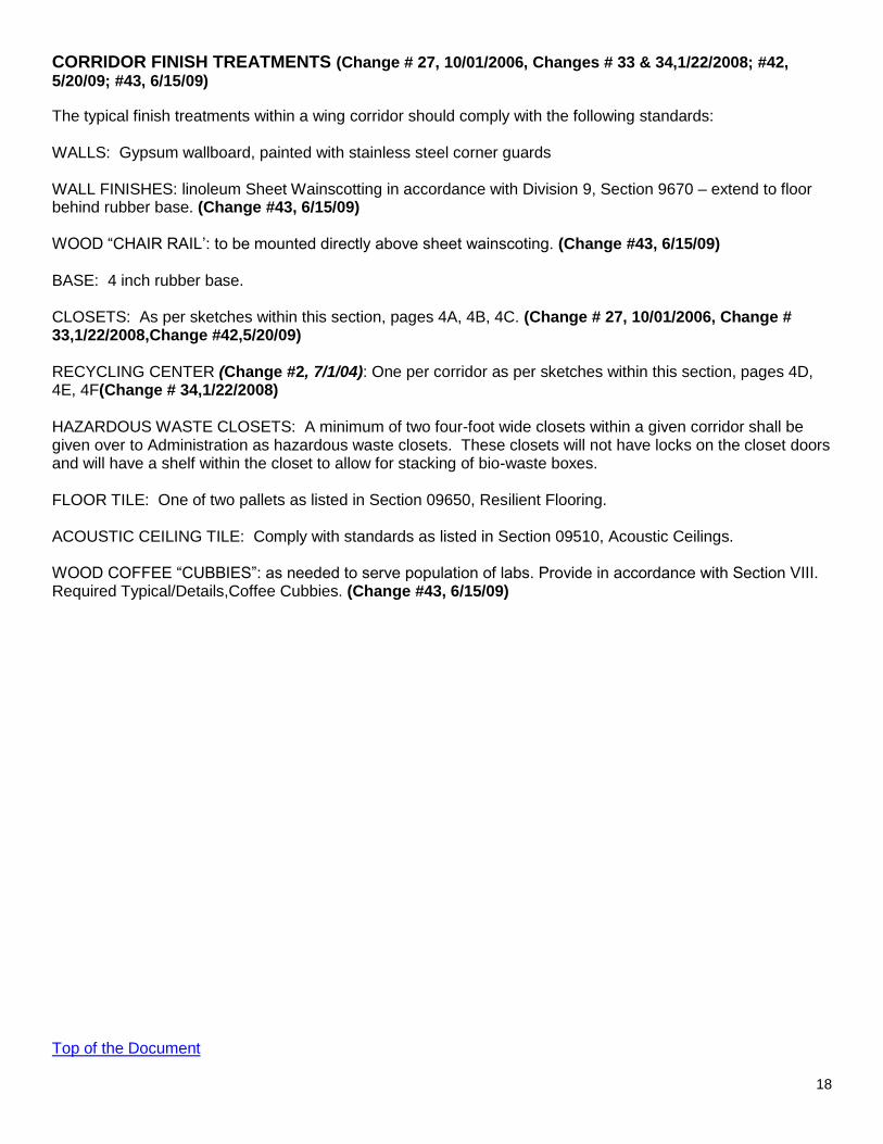
CORRIDOR FINISH TREATMENTS (Change # 27, 10/01/2006, Changes # 33 & 34,1/22/2008; #42, 5/20/09; #43, 6/15/09)
The typical finish treatments within a wing corridor should comply with the following standards: WALLS: Gypsum wallboard, painted with stainless steel corner guards WALL FINISHES: linoleum Sheet Wainscotting in accordance with Division 9, Section 9670 – extend to floor behind rubber base. (Change #43, 6/15/09) WOOD “CHAIR RAIL’: to be mounted directly above sheet wainscoting. (Change #43, 6/15/09) BASE: 4 inch rubber base. CLOSETS: As per sketches within this section, pages 4A, 4B, 4C. (Change # 27, 10/01/2006, Change # 33,1/22/2008,Change #42,5/20/09) RECYCLING CENTER (Change #2, 7/1/04): One per corridor as per sketches within this section, pages 4D, 4E, 4F(Change # 34,1/22/2008) HAZARDOUS WASTE CLOSETS: A minimum of two four-foot wide closets within a given corridor shall be given over to Administration as hazardous waste closets. These closets will not have locks on the closet doors and will have a shelf within the closet to allow for stacking of bio-waste boxes. FLOOR TILE: One of two pallets as listed in Section 09650, Resilient Flooring. ACOUSTIC CEILING TILE: Comply with standards as listed in Section 09510, Acoustic Ceilings. WOOD COFFEE “CUBBIES”: as needed to serve population of labs. Provide in accordance with Section VIII. Required Typical/Details,Coffee Cubbies. (Change #43, 6/15/09) Top of the Document
19
Top of the Document

20
Top of the Document

21
Top of the Document

22
Top of the Document

23
Top of the Document

24
Top of the Document

25
XOMAT POLICY
This policy is established to reduce the number of flooding incidents caused directly or indirectly by XOMAT film processor equipment. Drains clogged from XOMATS cause substantial flooding damage to occupants on the floor below. All new and existing installations will have the following: Ventilation: Prior to installation of a processor, BS&O will retain the services of a licensed air-balancing contractor to determine if the ventilation rates are adequate. If the report shows the room to be deficient, HVAC modifications will be made prior to the installation of the film processing equipment, with charging instructions from the department. Floors and Drains: Floors will be sealed with the Medinteck welded seam solid vinyl flashcove system or equal and pitched from the door, walls and cabinets to the drain. A four inch drain will be installed and be located close to, but not obstructed by, the film processor. Locks: The locksets used for the rooms with film processing equipment will allow both the user and BS&O access. This is to enable BS&O to secure the area if there is a flood. Equipment Connections: All Flexible hoses used to connect utilities to the film processor will be of a non-burst reinforced material. A stainless steel or aluminum drain pan will be installed under the processor. The drain from this pan will be piped into the floor drain. Drain Service: The services of a commercial firm (Parker X-Ray or approved equal) will be contracted to assure that all the drains from the processor are regularly cleaned. This contract will be held by the department and will include as a minimum: Cleaning the drain that is located after the developer on a monthly basis (or more often if needed). Cleaning process should include: application of granular "fotex" powder for 15 to 20 minutes and then flushing with water through the drain to dissolve the developer hardening clogs in the drain trap. A method of documentation will be developed. The costs to comply with this policy are the responsibility of the department using the Xomat film processing equipment Top of the Document
26
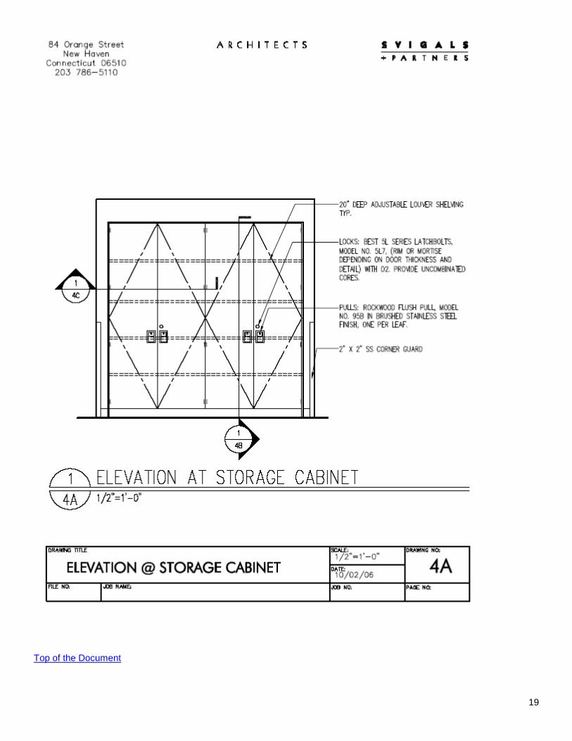
BIOLOGICAL SAFETY CABINET INSTALLATION The minimum clearance required from the top of the biological safety cabinet (BSC) to the ceiling is ten inches. This will allow for proper exhaust airflow and repair of the BSC when necessary. A minimum three-inch clearance on the side and 1.5 inch clearance in the back are recommended. BSCs must be placed away from doors as well as ventilation supply and exhaust vents to reduce air currents around the BSC. The electrical outlet for a BSC must be a 20 amp dedicated circuit that is readily accessible for service and electrical safety testing. If a BSC is to be connected to a gas supply a flexible connector will be used. The connector must comply with the Standard for Connectors for Moveable Appliances, ANSI Z21.69. A quick-disconnect device is not recommended. An accessible manual shutoff valve must be installed at the outlet of the gas supply piping system upstream of the connector, as required by ANSI Z21.69. If a BSC is to be connected to vacuum, an appropriate flexible connection should be used.
Evaluation of Proposed Biological Safety Cabinet Locations
Biological safety cabinets can be located easily in most facilities. They should be kept away from drafts, convection currents, diffusers, and traffic paths. For further information or assistance, contact the Office of Environmental Health and Safety (7-2125). Top of the Document
A
B C
D
Air Diffuser in ceiling
BSC
BSC BSC
BSC BAD
traffic from door
BAD draft
GOOD
BETTER

27
REQUIRED PHYSICAL ACCESS POLICY (change # 47, 7/31/09) Dunnage on Roofs: If structural steel dunnage is installed to support equipment above roofs a minimum 30” clear must be provided between the roof surface and the lowest point of the dunnage. Do not locate anything requiring access on the underside of equipment on dunnage without prior Yale University PM approval. Accessibility of mechanical, electrical, plumbing and fire protection components: The following statement is required on each sheet of mechanical, electrical and plumbing construction documents:
Elements of the work are to be installed in a manner such that at Substantial Completion the following items, new or existing, shall be “fully and reasonably accessible”: all HVAC control boxes, all junction boxes, all valves (of every shape, sort, and function), all DDC control boxes, all electrical panels, all filters, all belts, all water coils, all disconnect switches and all maintenance access elements, including pull space. “Fully and reasonably accessible” shall be defined as: capable of being accessed for service, repair, or replacement by an average sized individual (on a ladder if necessary) and capable of being serviced or removed without removing, modifying, or distorting other components of the work. Conflict with meeting these requirements shall be brought to the attention of the owner’s representative in a timely manner and shall be changed at no cost to the owner.
Top of the Document

28
AIR HANDLING SYSTEMS POLICY In Support of Specific Space Uses Animal Spaces: Constant volume, pressure independent, supply boxes with terminal reheat coils, (some specific
uses may also require supplemental cooling coils), room temperature sensors and (where required) humidity sensors. Constant volume, pressure independent, exhaust boxes. CV supply and exhaust fans with humidification; 100% outside air, supply and exhaust. DDC monitoring and control of space, supply and exhaust fans.
Lab & Lab Support: 2-position, pressure independent supply boxes with terminal reheat coils and room temperature
sensors. Some lab support space with high heat loading may require a local, full re-circulating fan-coil unit. Two 2-position, pressure independent exhaust boxes; one for general room exhaust and one for hood exhaust. Box exhaust boxes combine into a single duct for room exhaust. Air flow position for the supply and exhaust boxes is tied to the room light switch, with a manual override. Perimeter radiation should be installed for labs with exposed walls. Supply and exhaust fans with variable frequency drives; 100% outside air. DDC monitoring and control of space, supply AHU and exhaust fans. Pneumatic controls may be used for small groupings of labs within existing buildings.
Offices Within Lab Areas: VAV, pressure independent supply boxes with terminal reheat coils (where required) and room
temperature sensors; VAV, pressure independent exhaust boxes. Perimeter radiation should be installed in offices with exposed walls. Supply and exhaust air served from Lab and Lab Support supply and exhaust fans above. Pneumatic controls may be used for office space.
Offices (In large groupings) & Common Space: VAV, pressure independent supply boxes and room temperature sensors; VAV, pressure
independent return air boxes. Supply fan with variable frequency drive, distributing return air mixed with the ASHRAE requirements of 20 cfm of outside air per person. DDC monitoring and control of AHU. Pneumatic controls may be used for space.
OR: Constant volume supply boxes with terminal reheat coils and room thermostats; ducted return air
to the air handling unit. CV supply fan distributing return air mixed with the ASHRAF, requirement of 20 cfm of outside air per person. DDC monitoring and control of AHU. Pneumatic controls may be used for space. In either scenario, perimeter radiation should be installed in spaces with exposed walls.
Top of the Document

29
POLICY FOR THE APPLICATION OF DDC CONTROLS
Application of DDC Controls • DDC will be utilized for monitoring and control of all space functions. • The design team shall meet with representatives from the user group(s), Project Management & Construction, and
Building Services & Operations during Preliminary Design Phase to define the requirements for the automatic temperature control sequence. At the conclusion of the meeting, the design team will have sufficient information to create a sequence of operations, points list and specifications for the project.
• At Preliminary Design, the points list, sequence of operations and specifications for automatic temperature controls
shall be completed and ready for review. • All control systems will be specified as BACnet-Lonmark compatible, the only acceptable products allowed are from
the following manufacturers: Seibe Environmental Controls Johnson Controls • All control sequences will be kept as simple as possible. • The control contractor will bid the DDC installation, termination, software design, and debugging of all controllers and
field devices. • At the owner's discretion, the control contractor may be brought in at the Design Development Phase. • All wiring and associated conduits pertaining to the control system can be bid under Division 16 at the owner's
discretion. • Devices such as control valves, valve and damper actuators can be bid and provided by the mechanical contractor
under Division 15, at the owner's discretion. • The application of backup pneumatic controllers will be limited to systems serving areas of critical nature. • Copies of interim control documentation and submittals will be made available to BS&O during construction for review
and a copy of the Field Record Drawings will be given to BS&O at the end of the project. • The Control Department Manager will review and approve all control submittals before any installations can be made. • Control System commissioning will be performed with a BS&O representative present to completely understand the
sequence of operations and verify system performance.
Top of the Document

30
Controls Policy: Off-hours set back policy The system should incorporate two independent volume controllers in a “typical” (+760 SF) lab * : 1. The light switch determines the amount of general exhaust 800 CFM (on position) versus 250 CFM (off position) 2. The hood sash position determines the amount of hood exhaust 920 CFM
(in use position) versus 300 CFM (in not used position) Each of these controllers acts independently creating four possible airflow combinations ranging from 4.6 AC/hr to 14.3 AC/hr (see table below). Twist timers are required to allow for research to be done in a darkened room. A sign will be mounted at the light switch stating, “Use twist timer if laboratory is occupied with lights out”. Twist timer will override the light switch controller to maintain full occupancy CFM flow. *CFM and SF stated here are examples only EXAMPLE:
BCMM
Typical Lab Size Floor Ceiling length width area height volume ft ft ft
2 ft ft3
29.58 25.67 759.32 9.5 7,213.53 Typical Lab Air Flow Light Switch Hood Sash / Switch
(920 cfm) "Open"
(300 cfm) "Closed"
"On" 14.3 exh based 9.1 exh based Air Changes Hr
(800 cfm) 1,720 cfm 1,100 cfm Lab Exhaust 1,600 cfm 980 cfm Lab Supply
"Off" 9.7 exh based 4.6 exh based Air Changes Hr (250 cfm) 1,170 cfm 550 cfm Lab Exhaust
1,050 cfm 430 cfm Lab Supply
Supply Air = Hood Exh. + Gen. Exh. - 120 cfm Top of the Document
31
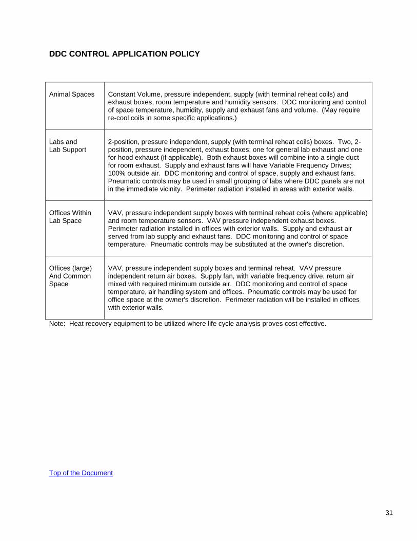
DDC CONTROL APPLICATION POLICY
Animal Spaces
Constant Volume, pressure independent, supply (with terminal reheat coils) and exhaust boxes, room temperature and humidity sensors. DDC monitoring and control of space temperature, humidity, supply and exhaust fans and volume. (May require re-cool coils in some specific applications.)
Labs and Lab Support
2-position, pressure independent, supply (with terminal reheat coils) boxes. Two, 2-position, pressure independent, exhaust boxes; one for general lab exhaust and one for hood exhaust (if applicable). Both exhaust boxes will combine into a single duct for room exhaust. Supply and exhaust fans will have Variable Frequency Drives; 100% outside air. DDC monitoring and control of space, supply and exhaust fans. Pneumatic controls may be used in small grouping of labs where DDC panels are not in the immediate vicinity. Perimeter radiation installed in areas with exterior walls.
Offices Within Lab Space
VAV, pressure independent supply boxes with terminal reheat coils (where applicable) and room temperature sensors. VAV pressure independent exhaust boxes. Perimeter radiation installed in offices with exterior walls. Supply and exhaust air served from lab supply and exhaust fans. DDC monitoring and control of space temperature. Pneumatic controls may be substituted at the owner's discretion.
Offices (large) And Common Space
VAV, pressure independent supply boxes and terminal reheat. VAV pressure independent return air boxes. Supply fan, with variable frequency drive, return air mixed with required minimum outside air. DDC monitoring and control of space temperature, air handling system and offices. Pneumatic controls may be used for office space at the owner's discretion. Perimeter radiation will be installed in offices with exterior walls.
Note: Heat recovery equipment to be utilized where life cycle analysis proves cost effective.
Top of the Document

32
GLASS PIPE REMOVAL POLICY
1. In general, glass waste piping should be removed wherever possible and practical. Field conditions and budget restrictions may limit the extent of removal.
2. In large, multi-room renovations where the space above the ceiling is exposed, remove all glass piping back
to the fixture and the riser. 3. In small, single room renovations where the space above the ceiling is exposed and the glass piping
connects to fixtures above, remove all glass piping within the room, back to the fixtures above, and back to the riser (if the riser is in the space). If the glass piping passes through the space without any connections to fixtures above and does not show signs of leaking, leave the glass pipe in place. If the glass piping passes through the space and shows signs of leaking, remove the glass piping in the room and back to the riser (if the riser is in the space)
Top of the Document

33
LABORATORY AIR FLOW RATE
A new Yale University standard air flow rate of 9 AC/hr (air changes per hour) has been established for all new laboratory space.
Top of the Document

34
MC CABLE POLICY
1. MC cable (BX with a copper ground) may be used in office areas, classrooms, lecture halls and auditoria for lighting and receptacle circuits. Wire/shielding size per code and application (no minimum size requirement). Homeruns to panels (that is, all work in corridor) shall be EMT, with a minimum size of ¾".
2. MC cable may be used in laboratory areas for lighting fixtures and switches only. Wire/shielding size per
code and application (no minimum size requirement). Homeruns to panels (that is, all work in corridor) shall be EMT, with a minimum size of ¾".
3. EMT shall be used for laboratory power circuits, including the homerun back to the panel (that is, all work in
corridor), with a minimum size of ¾". 4. Minimum size wire in the MC cable should be specified as #12. Top of the Document

35
AUTOCLAVE ROOM REQUIREMENTS
1. Floor must be either a monolithic troweled on epoxy resin floor (see Section 09800) or, a continuous welded seam vinyl sheet floor, Armstrong "Media-Tec", with integral core base.
2. Provide a floor drain within room. If practical/possible, the floor should be modified to pitch to drain.
Top of the Document

36
TELECOM POLICY
(See also Low Voltage System Standards within this Section.)
1. Telecom installations shall comply with requirements of EIA/TIA Standards 568, dated July 1991, and
Standard 569, dated October 1990. 2. Provide a 2" sleeve above entry doors at corridor walls. 3. At all Telecom closets, provide ¾" 4 x 8 plywood backboard. Paint grey. Provide Wiremold 3000 mounted
vertically adjacent to the backboard with duplex outlets 12" o.c. with every third outlet on a separate circuit. 4. Provide mechanical ventilation at Telecom closets that will house data hubs. 5. Provide one "drop" with pull string per office. A drop consists of a 1" conduit from a 4 x 4 wall box extended
above the ceiling and terminated with a bushing. 6. J-Hooks can be used as wiring supports within program spaces if route is not too long; otherwise, conduit is
to be used. Top of the Document
37
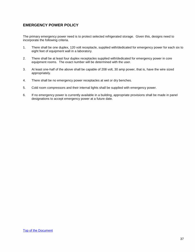
EMERGENCY POWER POLICY
The primary emergency power need is to protect selected refrigerated storage. Given this, designs need to incorporate the following criteria. 1. There shall be one duplex, 120 volt receptacle, supplied with/dedicated for emergency power for each six to
eight feet of equipment wall in a laboratory. 2. There shall be at least four duplex receptacles supplied with/dedicated for emergency power in core
equipment rooms. The exact number will be determined with the user. 3. At least one-half of the above shall be capable of 208 volt, 30 amp power, that is, have the wire sized
appropriately. 4. There shall be no emergency power receptacles at wet or dry benches. 5. Cold room compressors and their internal lights shall be supplied with emergency power. 6. If no emergency power is currently available in a building, appropriate provisions shall be made in panel
designations to accept emergency power at a future date. Top of the Document

38
LOW VOLTAGE SYSTEM STANDARDS
The following are the Yale School of Medicine's Standards for the installation of low voltage wiring and fiber: Cables routed in corridors and public areas shall be run in j-hooks, cable trays, or conduit as determined by Yale. 1. Cable trays shall be rung type and shall be installed extending from the floor Telecom closet through the
entire length of the corridor. Nominal tray size shall be 6 inch wide by 3 inch deep, depending on space density. Trays shall connect directly into the floor Telecom closet, or be connected with sleeves. In cases where there is no room for cable trays, conduit(s) should be installed. Sizes of conduit, associated junction boxes and routing shall be specified by the project engineer in agreement with the BS&O Department and Yale University telecom design standards. Cable trays could also support the needs of other low voltage and fiber systems such as security and building controls. (In the areas where conduit is used, each system would require dedicated conduits.) Conduits to be marked at 25 foot intervals to clearly identify the contained system.
2. A two-inch diameter sleeve shall be installed above each corridor door to connect the cable tray or conduit
system to the spaces served. Connections to trays located on opposite side of the corridor require either conduit or wiring, neatly bundled and secured, crossing the corridor. Within the user space, cables above dropped ceiling would be routed using split rings. Conduit would be used only in situations where data cables (not fiber) require electro-magnetic shielding from lamp ballasts, motors, power cables, or transformers.
3. Drops for phone and data, from the above ceiling system described in 2 above shall be conduit installed
within walls down to wall mounted outlet boxes or wiremold. The top of the conduit shall be open and accessible above the drop ceiling level.
4. Use of flexible conduit (to house low voltage wiring) will be allowed ONLY for short distances to a maximum
of 6 feet. 5. Each Low Voltage System (Telecommunications, Security and Controls) shall install all wiring and cabling in
a neat and orderly manner. These wires and cables shall be bundled together and clearly marked and identified at 25 intervals (or at key junction points) using plastic cable tags. wires and cables added to existing cable tray-runs shall be placed adjacent to existing cables of the same system and tie-wrapped to the bundle to maintain a neat and orderly tray arrangement.
6. color codes for identifying systems are as follows: security systems ............................................ blue building controls ............................................. green telecom/data .................................................. yellow fire alarms ...................................................... red Fire alarm systems shall remain installed in dedicated conduit.
Top of the Document
39
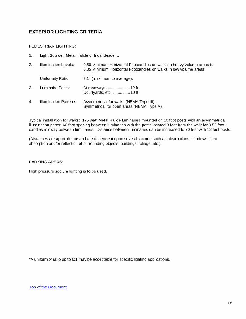
EXTERIOR LIGHTING CRITERIA
PEDESTRIAN LIGHTING: 1. Light Source: Metal Halide or Incandescent. 2. Illumination Levels: 0.50 Minimum Horizontal Footcandles on walks in heavy volume areas to: 0.35 Minimum Horizontal Footcandles on walks in low volume areas. Uniformity Ratio: 3:1* (maximum to average). 3. Luminaire Posts: At roadways ...................... 12 ft. Courtyards, etc. ................ 10 ft. 4. Illumination Patterns: Asymmetrical for walks (NEMA Type III). Symmetrical for open areas (NEMA Type V). Typical installation for walks: 175 watt Metal Halide luminaries mounted on 10 foot posts with an asymmetrical illumination patter; 60 foot spacing between luminaries with the posts located 3 feet from the walk for 0.50 foot-candles midway between luminaries. Distance between luminaries can be increased to 70 feet with 12 foot posts. (Distances are approximate and are dependent upon several factors, such as obstructions, shadows, light absorption and/or reflection of surrounding objects, buildings, foliage, etc.) PARKING AREAS: High pressure sodium lighting is to be used. *A uniformity ratio up to 6:1 may be acceptable for specific lighting applications. Top of the Document

40
REQUIREMENTS FOR REDUNDANCY AND STANDBY ELECTRIC POWER AS APPLIED TO BUILDING SYSTEMS SERVING ANIMAL ROOMS. The following requirements apply to new or major renovations to building systems serving animal rooms. Redundancy shall be provided within the following system designations: Exhaust Air: Two separately driven exhaust air fans shall be installed. Each fan shall have the capacity to
provide 100% of the exhaust air requirements of the space. The electric power connected to each fan motor shall be fed through a dedicated circuit. Redundant ductwork is not required.
Control Air: Two separately driven control air compressors shall be installed. Each compressor shall have the
capacity to provide 100% of the control air requirements of the space. The electric power connected to each compressor motor shall be fed through a dedicated circuit. Redundant compressed air tanks are not required.
Steam Condensate: Two separately driven condensate pumps shall be installed. The electric power connected to
each pump motor shall be fed through a dedicated circuit. Redundant condensate receivers are not required.
Liquefied Animal Waste: In locations where animal waste drains to a sump, duplex sewage ejector pumps shall
be installed. The electric power connected to each pump motor shall be fed through a dedicated circuit. Redundant sump tanks are not required.
Redundancy to be determined at time of design: Supply air: If redundant supply air fans are a design requirement, each fan shall be separately driven and have
the capacity to provide 100% of the supply air requirements of the space. The fans may be mounted within the same air handler or in separate air handlers as space permits. The electric power connected to each fan motor shall be fed through a dedicated circuit. Redundant ductwork is not required.
Standby Electric Power shall be provided to the following building system equipment: Exhaust air fan motors. HVAC control panels (all). Steam condensate pumps. Liquefied animal waste sump pumps. Standby Electric Power to be determined at time of design for the following equipment: Supply air fan motors. The transfer from normal electric power to standby electric power on a system and component level shall be a manual operation. Top of the Document


