DESIGN STANDARDS ELECTRICAL SCHEMATIC DIAGRAMS · DESIGN STANDARDS ELECTRICAL SCHEMATIC DIAGRAMS...
14
LHC Project Document No. LHC-PM-QA-403.00 rev 1.0 CERN Div./Group or Supplier/Contractor Document No. - EDMS Document No. 103568 Date: 2000-07-05 the Large Hadron Collider project CERN CH-1211 Geneva 23 Switzerland Quality Assurance Standard DESIGN STANDARDS ELECTRICAL SCHEMATIC DIAGRAMS Abstract This document provides standards for all electrical schematic diagrams for the LHC and its detectors. It covers: ! High and low voltage distribution diagrams. ! Relay and automatism diagrams. ! Lighting, power and earth protection diagrams. ! LHC main ring magnets cabling diagrams. ! Cooling and ventilation relay and automatism diagrams. Prepared by : Martial Dujardin ST/EL [email protected] Joaquin Inigo-Golfin ST/CV [email protected] Checked by : LHC Quality Assurance Working Group Approved by : Paul Faugeras Deputy to LHC Project Leader for Quality Assurance
Transcript of DESIGN STANDARDS ELECTRICAL SCHEMATIC DIAGRAMS · DESIGN STANDARDS ELECTRICAL SCHEMATIC DIAGRAMS...
LHC Project Document No.
LHC-PM-QA-403.00 rev 1.0CERN Div./Group or Supplier/Contractor Document No.
-EDMS Document No.
103568
Date: 2000-07-05
theLargeHadronColliderproject
CERNCH-1211 Geneva 23Switzerland
Quality Assurance Standard
DESIGN STANDARDSELECTRICAL SCHEMATIC DIAGRAMS
AbstractThis document provides standards for all electrical schematic diagrams for the LHC andits detectors. It covers:
! High and low voltage distribution diagrams.
! Relay and automatism diagrams.
! Lighting, power and earth protection diagrams.
! LHC main ring magnets cabling diagrams.
! Cooling and ventilation relay and automatism diagrams.
Prepared by :
Martial DujardinST/EL
[email protected] Inigo-Golfin
Checked by :
LHC Quality AssuranceWorking Group
Approved by :
Paul FaugerasDeputy to LHC Project
Leader for QualityAssurance
LHC Project Document No.
LHC-PM-QA-403.00 rev 1.0
Page 2 of 14
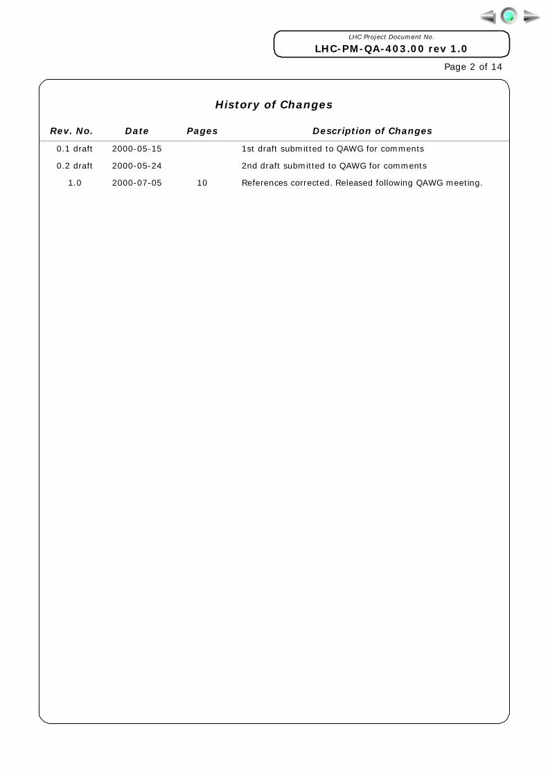
History of Changes
Rev. No. Date Pages Description of Changes
0.1 draft
0.2 draft
1.0
2000-05-15
2000-05-24
2000-07-05 10
1st draft submitted to QAWG for comments
2nd draft submitted to QAWG for comments
References corrected. Released following QAWG meeting.
LHC Project Document No.
LHC-PM-QA-403.00 rev 1.0
Page 3 of 14
Table of Contents
1. PURPOSE ............................................................................................. 4
2. POLICY ................................................................................................ 4
3. SCOPE.................................................................................................. 4
4. RESPONSIBILITIES .............................................................................. 4
5. DRAWING PREPARATION - GENERAL .................................................... 55.1 DRAWING SIZES .................................................................................. 55.2 TITLE BLOCK ....................................................................................... 55.3 MODIFICATION LIST ............................................................................. 6
6. NUMBERING SCHEMES ......................................................................... 66.1 DIAGRAMS PRODUCED BY ST/EL............................................................. 76.2 DIAGRAMS PRODUCED BY ST/CV ............................................................ 7
7. ARCHIVING PROCESS........................................................................... 77.1 ST/EL ELECTRICAL DIAGRAMS................................................................ 77.2 ST/CV ELECTRICAL DIAGRAMS ............................................................... 8
8. HIGH AND LOW VOLTAGE DISTRIBUTION UNIFILAR DIAGRAMS ........... 88.1 FILE NAMING CONVENTION.................................................................... 8
9. RELAY AND AUTOMATISM DIAGRAMS ................................................... 89.1 FILE NAMING CONVENTION.................................................................... 8
10. LIGHTING, POWER AND EARTH PROTECTION DIAGRAMS ...................... 910.1 FILE NAMING CONVENTION.................................................................... 9
11. LHC MAIN RING MAGNETS CABLING DIAGRAMS.................................... 9
12. COOLING AND VENTILATION RELAY AND AUTOMATISM DIAGRAMS .... 1012.1 FILE NAMING CONVENTION...................................................................10
13. RELATED DOCUMENTATION................................................................ 10
14. ANNEXES ........................................................................................... 10

LHC Project Document No.
LHC-PM-QA-403.00 rev 1.0
Page 4 of 14
1. PURPOSE
To provide standards for all electrical schematic diagrams for the Large HadronCollider (LHC) and its detectors.
2. POLICY
All electrical schematic diagrams for the LHC project shall be created with a ComputerAided Design (CAD) system, in accordance with the general quality assurance policy ofthe LHC project.
The CAD systems used for electrical schematic diagrams prepared at CERN areAutoCAD1, the AutoCAD add-on application Alpage-Elec2, and SEE 30002.
All electrical schematic diagrams prepared at CERN, and referenced in a CERNcontractual document, shall incorporate the appropriate CERN title block. The drawingtittle shall be written in English only or English and French.
All electrical schematics diagrams shall be stored in the CERN Drawing Directory(CDD) with the relevant descriptive information and identified by a unique drawingnumber defined in accordance with the CERN Drawing Directory rules as described inthe “CDD Manual”[ 1 ]. Diagrams may be stored as Hewlett Packard Graphic Language(HPGL) plot files and native CAD files or as HPGL plot files only.
All electrical schematic diagrams shall be submitted to a review and approval processbefore being released as described in "Drawing Management and Control", [ 2 ].
New versions of released diagrams shall be submitted to the same review andapproval process as the original diagrams.
3. SCOPE
This standard is applicable to:
All electrical schematic diagrams for the LHC and its detectors. This includes:
! High and low voltage distribution schematic diagrams.
! Relay, wiring and automatism schematic diagrams.
! Lighting, power and earth protection schematic diagrams.
! LHC main ring magnets cabling schematic diagrams.
! Cooling and ventilation relay and automatism diagrams.
4. RESPONSIBILITIES
Managers, Supervisors and Project Engineers (PE) at CERN working on the LHC Projectare responsible for:
! Ensuring that designers and draughtsman are aware of and understand theprocedures described in the present document.
! Ensuring that these design standards are fully implemented in their design.
– 1 AutoCAD is a registered trademark of Autodesk, Inc.2 Alpage-Elec and SEE 3000 are registered trademarks of Ige-Xao
LHC Project Document No.
LHC-PM-QA-403.00 rev 1.0
Page 5 of 14
! Ensuring that industrial support personnel assigned to CAD design and draftingactivity is suitably trained and has been informed of CERN practices before startingwork.
Every designer and draughtsman is responsible for producing diagrams in compliancewith these design standards.
The ST Division is responsible for the definition of equipment codes used for electricalschematic diagrams. Equipment codes for LHC equipment have to be approved by theLHC Co-ordinator for equipment codes [ 3 ].
The diagrams in the categories below are produced under the responsibility of the STDivision Electrical Engineering and Telecom group (ST/EL).
! High and low voltage distribution schematic diagrams.
! Relay, wiring and automatism schematic diagrams.
! Lighting, power and earth protection schematic diagrams.
! LHC main ring magnets cabling schematic diagrams.
Cooling and ventilation relay and automatism diagrams are produced under theresponsibility of the ST Division Cooling and Ventilation group (ST/CV).
5. DRAWING PREPARATION - GENERAL
5.1 DRAWING SIZES
Unless otherwise specified all diagrams shall be made on one of the followingInternational Organization for Standardization (ISO) standard sizes:
Horizontal A0 (1189 x 841 mm)
A1 (841 x 594 mm)
A2 (594 x 420 mm)
A3 (420 x 297 mm)
Vertical A4 (297 x 210 mm)
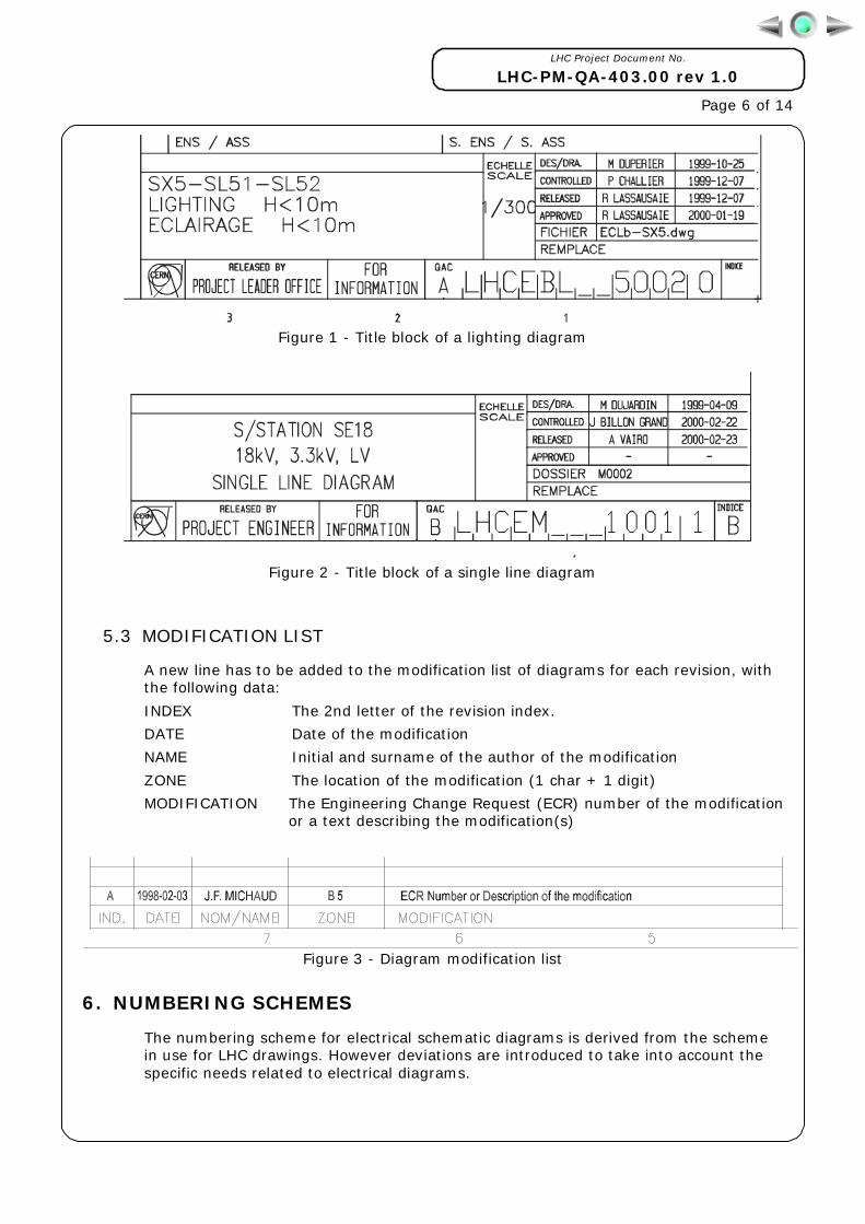
5.2 TITLE BLOCK
Title blocks differ slightly depending on the CAD application used for preparing thediagram, but they are in all cases compatible with CDD.
TITLE The diagram‘s title in English or in English and French
DRAWING NUMBER As described in chapter 6.
QA CATEGORY The code of the quality assurance category (1 char), see [ 4 ]
DRAWING SIZE The 2nd digit of the size (3 for size A3)
REVISION INDEX The 2nd letter of the revision index
AUTHOR The author’s initial and surname
DATE The date of creation of the drawing in ISO format (yyyy-mm-dd)
SCALE Used only for lighting, power and earth protection diagrams
LHC Project Document No.
LHC-PM-QA-403.00 rev 1.0
Page 6 of 14
Figure 1 - Title block of a lighting diagram
Figure 2 - Title block of a single line diagram
5.3 MODIFICATION LIST
A new line has to be added to the modification list of diagrams for each revision, withthe following data:
INDEX The 2nd letter of the revision index.
DATE Date of the modification
NAME Initial and surname of the author of the modification
ZONE The location of the modification (1 char + 1 digit)
MODIFICATION The Engineering Change Request (ECR) number of the modificationor a text describing the modification(s)
Figure 3 - Diagram modification list
6. NUMBERING SCHEMES
The numbering scheme for electrical schematic diagrams is derived from the schemein use for LHC drawings. However deviations are introduced to take into account thespecific needs related to electrical diagrams.
LHC Project Document No.
LHC-PM-QA-403.00 rev 1.0
Page 7 of 14
6.1 DIAGRAMS PRODUCED BY ST/EL
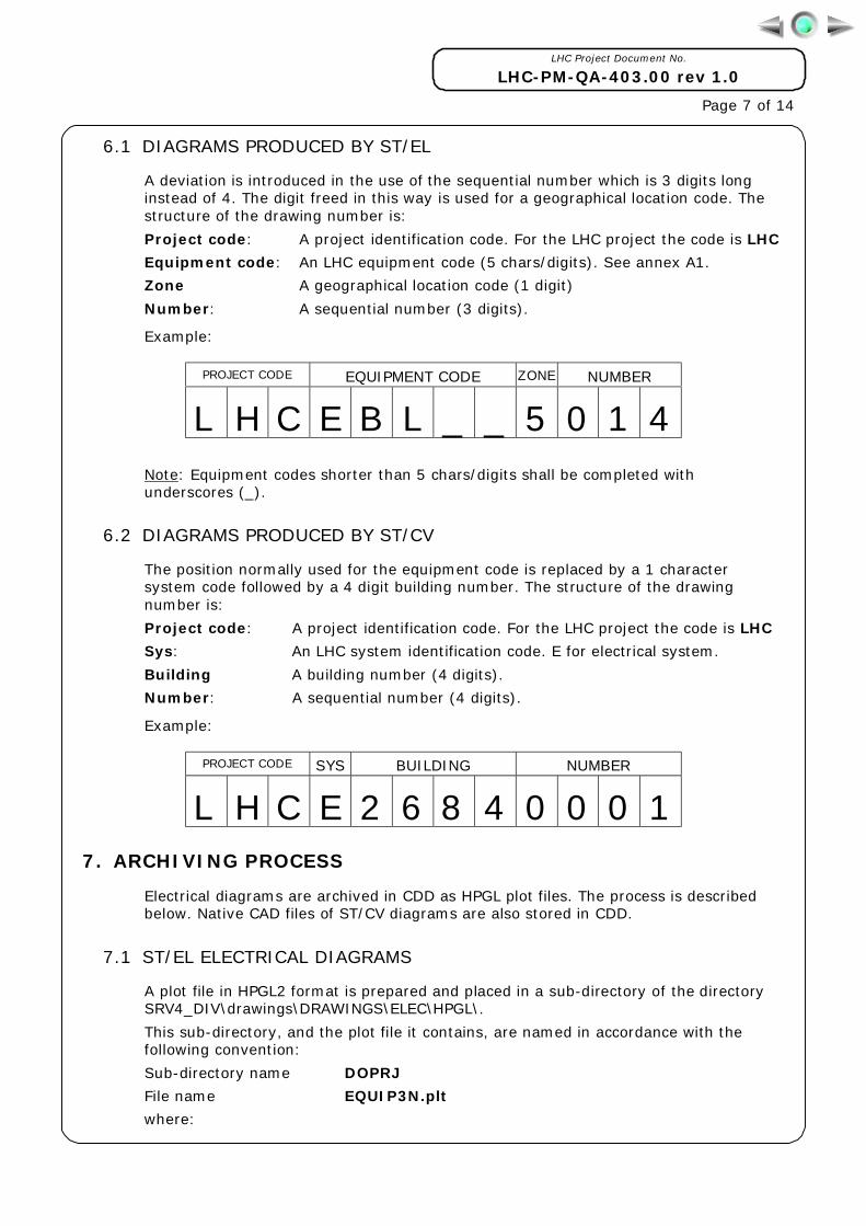
A deviation is introduced in the use of the sequential number which is 3 digits longinstead of 4. The digit freed in this way is used for a geographical location code. Thestructure of the drawing number is:
Project code: A project identification code. For the LHC project the code is LHC
Equipment code: An LHC equipment code (5 chars/digits). See annex A1.
Zone A geographical location code (1 digit)
Number: A sequential number (3 digits).
Example:
PROJECT CODE EQUIPMENT CODE ZONE NUMBER
L H C E B L _ _ 5 0 1 4Note: Equipment codes shorter than 5 chars/digits shall be completed withunderscores (_).
6.2 DIAGRAMS PRODUCED BY ST/CV
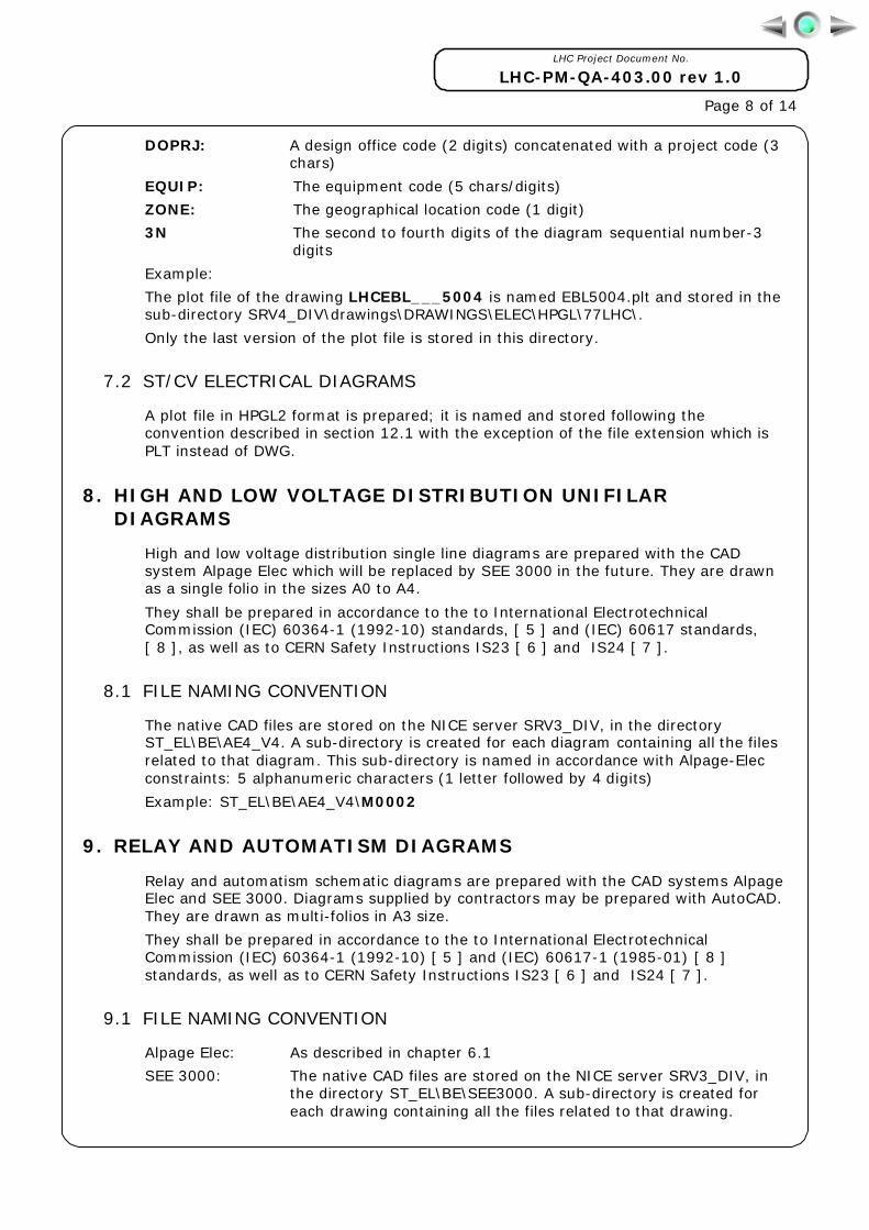
The position normally used for the equipment code is replaced by a 1 charactersystem code followed by a 4 digit building number. The structure of the drawingnumber is:
Project code: A project identification code. For the LHC project the code is LHC
Sys: An LHC system identification code. E for electrical system.
Building A building number (4 digits).
Number: A sequential number (4 digits).
Example:
PROJECT CODE SYS BUILDING NUMBER
L H C E 2 6 8 4 0 0 0 17. ARCHIVING PROCESS
Electrical diagrams are archived in CDD as HPGL plot files. The process is describedbelow. Native CAD files of ST/CV diagrams are also stored in CDD.
7.1 ST/EL ELECTRICAL DIAGRAMS
A plot file in HPGL2 format is prepared and placed in a sub-directory of the directorySRV4_DIV\drawings\DRAWINGS\ELEC\HPGL\.
This sub-directory, and the plot file it contains, are named in accordance with thefollowing convention:
Sub-directory name DOPRJ
File name EQUIP3N.plt
where:
LHC Project Document No.
LHC-PM-QA-403.00 rev 1.0
Page 8 of 14
DOPRJ: A design office code (2 digits) concatenated with a project code (3chars)
EQUIP: The equipment code (5 chars/digits)
ZONE: The geographical location code (1 digit)
3N The second to fourth digits of the diagram sequential number-3digits
Example:
The plot file of the drawing LHCEBL___5004 is named EBL5004.plt and stored in thesub-directory SRV4_DIV\drawings\DRAWINGS\ELEC\HPGL\77LHC\.
Only the last version of the plot file is stored in this directory.
7.2 ST/CV ELECTRICAL DIAGRAMS
A plot file in HPGL2 format is prepared; it is named and stored following theconvention described in section 12.1 with the exception of the file extension which isPLT instead of DWG.
8. HIGH AND LOW VOLTAGE DISTRIBUTION UNIFILARDIAGRAMS
High and low voltage distribution single line diagrams are prepared with the CADsystem Alpage Elec which will be replaced by SEE 3000 in the future. They are drawnas a single folio in the sizes A0 to A4.
They shall be prepared in accordance to the to International ElectrotechnicalCommission (IEC) 60364-1 (1992-10) standards, [ 5 ] and (IEC) 60617 standards,[ 8 ], as well as to CERN Safety Instructions IS23 [ 6 ] and IS24 [ 7 ].
8.1 FILE NAMING CONVENTION
The native CAD files are stored on the NICE server SRV3_DIV, in the directoryST_EL\BE\AE4_V4. A sub-directory is created for each diagram containing all the filesrelated to that diagram. This sub-directory is named in accordance with Alpage-Elecconstraints: 5 alphanumeric characters (1 letter followed by 4 digits)
Example: ST_EL\BE\AE4_V4\M0002
9. RELAY AND AUTOMATISM DIAGRAMS
Relay and automatism schematic diagrams are prepared with the CAD systems AlpageElec and SEE 3000. Diagrams supplied by contractors may be prepared with AutoCAD.They are drawn as multi-folios in A3 size.
They shall be prepared in accordance to the to International ElectrotechnicalCommission (IEC) 60364-1 (1992-10) [ 5 ] and (IEC) 60617-1 (1985-01) [ 8 ]standards, as well as to CERN Safety Instructions IS23 [ 6 ] and IS24 [ 7 ].
9.1 FILE NAMING CONVENTION
Alpage Elec: As described in chapter 6.1
SEE 3000: The native CAD files are stored on the NICE server SRV3_DIV, inthe directory ST_EL\BE\SEE3000. A sub-directory is created foreach drawing containing all the files related to that drawing.
LHC Project Document No.
LHC-PM-QA-403.00 rev 1.0
Page 9 of 14
Example: ST_EL\BE\SEE3000\71LHC\EM3001
10. LIGHTING, POWER AND EARTH PROTECTION DIAGRAMS
Lighting, power and earth protection schematic diagrams are combinations of anelectrical schematic diagram and an equipment installation layout.
They are prepared with AutoCAD. The parts list of equipment is prepared with the helpof a CERN developed AutoCAD application named ATT_TAB. This application isdescribed in the document “Etude et développement d’applications dansl’environnement DAO AutoCAD pour l’aide à la gestion d’études électriques" written byA. Croissant in 1992.
They shall be prepared in accordance to the International Electrotechnical Commission(IEC) 60617 standards, [ 8 ], as well as to CERN Safety Instructions IS23, [ 6 ] andIS24, [ 7 ].
The following rules shall be respected when preparing a drawing:
! The schematic part is drawn on the layer "SCHEMA".
! The installation layout part is drawn on the layer "IMP".
! They are drawn using the symbols library available on the NICE serverI:\SRV4_DIV\drawings\DRAWINGS\ELEC\BE_LHC\STANDARD\WB
10.1 FILE NAMING CONVENTION
The native CAD files are stored on the NICE server SRV4_DIV\drawings\, in thedirectory DRAWINGS\ELEC\. A sub-directory is created for each set of diagrams. Thissub-directory, and the drawing files it contains, are named in accordance with thefollowing conventions:
Sub-directory name: DOPRJ
File name: EQUIPNUM.DWG
where:
DOPRJ: Design office code (2 digits) concatenated with a project code(3chars)
EQUIP: Equipment code (5 chars/digits)
NUM: Geographical location code (1 digit) + sequential number (4 digits)
DWG Standard AutoCAD file extension
Example:
The file of the diagram LHCEBL__5004 is named EBL5004.DWG and is stored in thedirectory I:\SRV4_DIV\drawings\DRAWINGS\ELEC\77LHC\
11. LHC MAIN RING MAGNETS CABLING DIAGRAMS
These schematic diagrams are made with AutoCAD. They follow the standardsdescribed in LHC-PM-QA-402.00 "Design Standards-Mechanical Engineering andInstallations" except for the pen sizes and colours.
They can only been printed on a colour plotter.
LHC Project Document No.
LHC-PM-QA-403.00 rev 1.0
Page 10 of 14
12. COOLING AND VENTILATION RELAY AND AUTOMATISMDIAGRAMS
Relay and automatism diagrams are prepared with the CAD systems ALPAGE ELEC andSEE 3000 both in A3 and A4 sizes.
Diagrams supplied by contractors may be prepared with AutoCAD. They are drawn asmulti-folios in A3 size.
Diagrams shall be prepared in accordance to the International ElectrotechnicalCommission (IEC) 60617 standards, [ 8 ].
12.1 FILE NAMING CONVENTION
The native CAD files are stored on the NICE server SRV4_DIV\drawings\ in thedirectory DRAWINGS\LHC. A sub-directory is created for each building, containing allthe files related to that building. This sub-directory is named according to the followingconvention:
Sub-directory name EBLDG1N
File name EBLDG3N.DWG
where:
EBLDG: The character E followed by the building number(4 digits), total 5digits
1N The first digit of the diagram sequential number-1 digit
3N The second to fourth digits of the diagram sequential number-3digits
DWG The Standard AutoCAD and Alpage Elec file extension
Example:
The diagram numbered LHCE31820004 is stored in the directory:
SRV4_DIV\drawings\DRAWINGS\LHC\E31820\E3182004.DWG
13. RELATED DOCUMENTATION
[ 1 ] CERN EST/98-01 (ISS) CDD Manual
[ 2 ] LHC-PM-QA-305.00 Drawing Management and Control
[ 3 ] LHC-PM-QA-204.00 Equipment Naming Conventions
[ 4 ] LHC-PM-QA-201.00 Quality Assurance Categories
[ 5 ] IEC 60364-1 (1992-10) Electrical installations of buildings
[ 6 ] TIS IS23 Criteria and standard test methods for the selectionof electric cables, wires and insulated parts withrespect to fire safety and radiation resistance
[ 7 ] TIS IS24 Regulations applicable to electrical installations
[ 8 ] IEC 60617 Graphical symbols for diagrams
14. ANNEXES
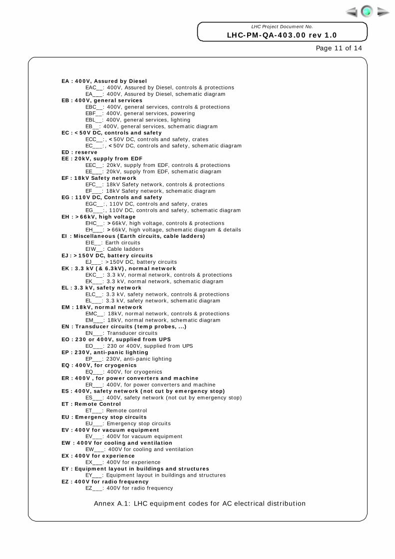
A.1 LHC equipment codes for AC electrical distribution
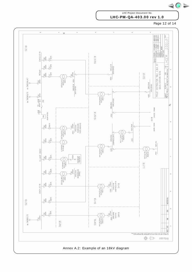
A.2 Example of an 18kV diagram
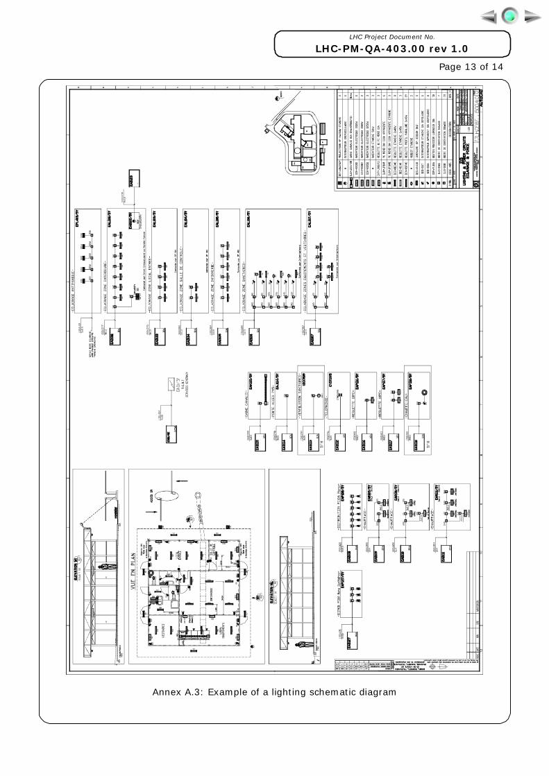
A.3 Example of a lighting schematic diagram
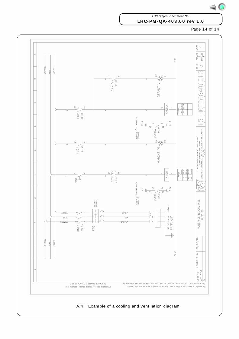
A.4 Example of a cooling and ventilation diagram
LHC Project Document No.
LHC-PM-QA-403.00 rev 1.0
Page 11 of 14
EA : 400V, Assured by Diesel
EAC__: 400V, Assured by Diesel, controls & protections EA___: 400V, Assured by Diesel, schematic diagram
EB : 400V, general services EBC__: 400V, general services, controls & protections EBF__: 400V, general services, powering EBL__: 400V, general services, lighting EB__: 400V, general services, schematic diagram
EC : <50V DC, controls and safety ECC__:, <50V DC, controls and safety, crates EC___:, <50V DC, controls and safety, schematic diagram
ED : reserve EE : 20kV, supply from EDF
EEC__: 20kV, supply from EDF, controls & protections EE___: 20kV, supply from EDF, schematic diagram
EF : 18kV Safety network EFC__: 18kV Safety network, controls & protections EF___: 18kV Safety network, schematic diagram
EG : 110V DC, Controls and safety EGC__:, 110V DC, controls and safety, crates EG___:, 110V DC, controls and safety, schematic diagram
EH : >66kV, high voltage EHC__: >66kV, high voltage, controls & protections EH___: >66kV, high voltage, schematic diagram & details
EI : Miscellaneous (Earth circuits, cable ladders) EIE__: Earth circuits EIW__: Cable ladders
EJ : >150V DC, battery circuits EJ___: >150V DC, battery circuits
EK : 3.3 kV (& 6.3kV), normal network EKC__: 3.3 kV, normal network, controls & protections EK___: 3.3 kV, normal network, schematic diagram
EL : 3.3 kV, safety network ELC__: 3.3 kV, safety network, controls & protections EL___: 3.3 kV, safety network, schematic diagram
EM : 18kV, normal network EMC__: 18kV, normal network, controls & protections EM___: 18kV, normal network, schematic diagram
EN : Transducer circuits (temp probes, ...) EN___: Transducer circuits
EO : 230 or 400V, supplied from UPS EO___: 230 or 400V, supplied from UPS
EP : 230V, anti-panic lighting EP___: 230V, anti-panic lighting
EQ : 400V, for cryogenics EQ___: 400V, for cryogenics
ER : 400V , for power converters and machine ER___: 400V, for power converters and machine
ES : 400V, safety network (not cut by emergency stop) ES___: 400V, safety network (not cut by emergency stop)
ET : Remote Control ET___: Remote control
EU : Emergency stop circuits EU___: Emergency stop circuits
EV : 400V for vacuum equipment EV___: 400V for vacuum equipment
EW : 400V for cooling and ventilation EW___: 400V for cooling and ventilation
EX : 400V for experience EX___: 400V for experience
EY : Equipment layout in buildings and structures EY___: Equipment layout in buildings and structures
EZ : 400V for radio frequencyEZ___: 400V for radio frequency
Annex A.1: LHC equipment codes for AC electrical distribution
LHC Project Document No.
LHC-PM-QA-403.00 rev 1.0
Page 12 of 14
Annex A.2: Example of an 18kV diagram
LHC Project Document No.
LHC-PM-QA-403.00 rev 1.0
Page 13 of 14
Annex A.3: Example of a lighting schematic diagram
LHC Project Document No.
LHC-PM-QA-403.00 rev 1.0
Page 14 of 14
A.4 Example of a cooling and ventilation diagram