
design report - Squarespace · PDF fileata jefferson middle school rebuild eugene school...
75
ATA JEFFERSON MIDDLE SCHOOL REBUILD EUGENE SCHOOL DISTRICT 4J EUGENE, OREGON JANUARY 28, 2015 SCHEMATIC DESIGN REPORT
Transcript of design report - Squarespace · PDF fileata jefferson middle school rebuild eugene school...

ata jefferson middle school rebuildeugene school district 4jeugene, oregon
january 28, 2015
schematic design report

iiiRowell Brokaw Architects PC and Opsis Architecture
ata jefferson middle school | eugene district 4j | schematic design report
TABLE OF CONTENTS
I. Project Team iii
II. Overall Project Design 1
Project Information 1
Process and Key Decisions 2
Organizational Diagrams 6
Plan Drawings 10
III. Schedule and Phasing 23
Graphic Schedule 23
Phasing Diagrams 24
IV. Building Space Program List 27
V. Building and Land Use Code 29
Code Summary 29
Code Analysis 30
VI. Outline Specification 31
VII. Project Systems Narratives 37
Civil 37
Landscape 40
Structural 43
Heating, Ventilation and Air Conditioning 48
Plumbing 54
Fire Suppression 58
Electrical 59
Low Voltage 64
Audio Visual 66
Food Service 70
Acoustics 72
VIII. Appendix Items (Not in this Document) 79
Schematic Design Drawing Set
Site and Plan Diagrams• Existing Site Plan• Phased Site Plans• Demolition Plans• Wall and Acoustical Assemblies
Building Space Program Document
Cost Estimate
Survey
GeoTech Report
SD Meeting Minutes
i

vRowell Brokaw Architects PC and Opsis Architecture
ata jefferson middle school | eugene district 4j | schematic design report
PROJECT TEAM
EUGENE SCHOOL DISTRICT 4J
Jon Lauch, Director Facilities Management
Bruce Foster, 4J Facilities Project Manager
DESIGN ADVISORY TEAM
ATA Jefferson Middle school
Jeffry Johnson, ATA Principal
Linda O’Shea, ATA Assistant Principal
Craig Smith, Board Member
Jon Lauch, Director Facilities Management and Transportation
Bruce Foster, 4J Facilities Project Manager
Cheryl Linder, Educational Support Services
Randy Bernstein, Secondary Education
Corianne Rice-Heinke, ATA Title 1 Coordinator
Kristina Molyneux-Brooks, ATA Language Arts
Courtney Stitt, ATA Mathematics
Daniel Morphosis, ATA Science and Track
Corey Rusco and Rena Robbins, ATA Custodial
DESIGN TEAM
rowell BrokAw ArchiTecTs, Pc (PriMe ArchiTecT)
Mark Young, AIA, Principal Architect
Elaine Lawson, AIA, Project Manager
Greg Brokaw, AIA, Architect
Patrick Hannah, Designer
Matt Travis, Designer
oPsis ArchiTecTure
(collABorATing ArchiTecT / educATion ArchiTecT)
Jim Kalvelage, AIA, Architect
Joe Baldwin, AIA, Architect
Alec Holser, AIA, Education Architect
Nate Wood, Designer
suB consulTAnTs
cAMeron MccArThy (lAndscAPe ArchiTecT)
Matt Koehler, ASLA, Principal Landscape Architect
Karim Hassanein, Designer
inTerfAce engineering (MechAnicAl / elecTricAl)
Steve Dacus, PE, Mechanical Engineer
Chris Larson, PE, Electrical Engineer
cATenA consulTing engineers (sTrucTurAl engineer)
Jason Thompson, PE, Structural Engineer
kPff consulTing engineers (civil engineer)
Matt Keenan, PE, Civil Engineer
Jlg engineering (low volTAge elecTricAl engineer)
Jeff Graper, PE, Low Voltage Engineer
BrAnch engineering (TrAffic engineer)
Damien Gilbert, PE, Traffic Engineer
Jlr design grouP (food service design)
Deon Richards, Principal Designer
lisTen AcousTics (AcousTicAl / AudiovisuAl engineer)
Tobin Cooley, PE
ArchiTecTurAl cosT consulTAnTs (cosT esTiMATor)
Seth Pszczolkowski, AIA
iii

1Rowell Brokaw Architects PC and Opsis Architecture
ata jefferson middle school | eugene district 4j | schematic design report
OVERALL PROJECT DESIGN
PROJECT INFORMATIONThe Arts and Technology Academy is a middle school in Eugene School District 4J, originally constructed in 1956 as Jefferson Middle School. The southwest classroom and science wing were added in 1959, 1961. A 1968 project also added the south classroom wing and the east gym (described in the program as Gym #2). The building has outgrown its use and does not meet current safety accessibility and energy standards. 4J has assessed the existing building condition, and the Design Team has confirmed that the majority of the building should be replaced instead of renovated.
The ATA Rebuild project will essentially replace the existing building with a new building. The only spaces to remain will be the 3 gymnasiums and the mechanical/electrical room. The Main Gym will undergo seismic upgrades, and upgrades to mechanical, electrical, acoustical and finishes. Gym #2 will be extended to allow full court basketball. The south gym will be converted to Band and Theater space. Most of the site will be redesigned with new landscape and hardscape.
ATA Site
W. 18th Ave.
W. 24th Ave.
Cham
bers
St.
Fillm
ore S
t.
Polk
St.
• Total Property Area: 770,140 sf (17.68 acres)• Project Site Area: 375,000 sf (8.61 acres)• Existing Building Area: 102,000 sf + 8,000sf covered walkway• New Building Area: 82,535 sf• Renovation Building Area: 15,300 sf• Mechanical Loft Area: 5,400 sf• Covered Outdoor Area: 4,280 sf

2 Rowell Brokaw Architects PC and Opsis Architecture
ii. overall project design | 01.28.2015
PROCESS + KEY DECISIONS
Programmming, Site Assessment and Master Plan
During Fall of 2013, the Design Team worked with 4J on a Master Plan to confirm the scope and feasibility of the project. There were two main objectives of the Master Plan. The first was to engage the ATA User Group in developing a space program for the new school. The second was to compare the feasibility of building on the existing site with the feasibility of trading land with the City of Eugene to build the school at the southeast corner of the City Park.
Starting with the 4J Ed Spec program for middle schools, the initial ATA program was developed with the ATA User Group through a series of programming meetings, exploration of middle school precedents, and tours of local and regional middle schools. The program is a living document that is refined during the design process as ideas are tested and reviewed. The current program is summarized in later section of this report, and the full program with space descriptions is available in the appendix.
With an intital program defined, conceptual plans were developed to analyze the cost of building on the two site options. 4J was interested in the new site because it would allow minimal disruption to ATA’s operation. The City was interested in the land swap because of the potential for improving the overall park layout and circulation.
Meetings were held with 4J and the City of Eugene to determine the process and cost for trading land. Trading land and building on the new site was determined to cost substantially more ($5-$6million project cost) than remaining on the existing site, mainly due to additional site development of replacement playing fields. The 4J School Board determined that additional funding was not available to build on the new site, and the Project Team was directed to design the new school on the existing site.
Existing and Final Site Location
Alternate Site Location

3Rowell Brokaw Architects PC and Opsis Architecture
ata jefferson middle school | eugene district 4j | schematic design report
Existing and Final Site Location
Alternate Site Location
Schematic Design Process
The design process began in the Summer of 2014. Based on programming discussions and initial schematic design meetings, guiding principles for the school were developed. Using these principles and the space program, multiple building plans and site plans were developed and reviewed with the User Group. During this phase of plan development, the first Public Meeting was held in September 2014 to solicit input from the greater school community and the surrounding neighborhood.
Using input from the User Group and the public, the building and site plan concepts were narrowed down until a single preferred concept was developed. Building form and character were then tested and reviewed with the User Group, and the preferred direction was developed into the Schematic Design. The building plan, site plan and building images were presented at the second and final Public Meeting in December 2014.

4 Rowell Brokaw Architects PC and Opsis Architecture
ii. overall project design | 01.28.2015
Guiding Principles
STEM Immersion ATA has received a series of grants to establish a fully integrated STEM curriculum. The building should help encourage group and project based learning. Classrooms will be organized by grade levels to facilitate collaboration between science, math, social sciences and language arts.
Embrace Arts and Diversity into STEMIntegrate the “A” (Arts) into STEM to blend creativity with technical knowledge. Allow STEM to be approachable and accessible to the diverse student poplulation of ATA.
Wholeness of School Community and between GradesATA culture emphasizes the whole school community over grade-level stratification. Maintain the nurturing, centralized community environment of ATA. With grade-level groupings, find ways to keep the students feel as part of a whole.
Welcoming and AccessibleThe site and building design should be approachable and comfortable for students and their families, many of whom may be intimidated by institutional settings. Wide demographic appeal with reconizable, enduring material.
A Good NeighborAs a public building in a large neighborhood park, the school serves as a neighborhood community center. It has a civic presence and should appear stable and grounded.
Building TeachesHow the building is built and operates should be displayed and expressed where possible. It can provide and support learning opportunities related to the STEM curriculum.
Connections between Indoor and Outdoor LearningProvide visual connections to the outdoors and physical exterior spaces that expand the learning environment. Extend STEM learning opportunities outdoors.

5Rowell Brokaw Architects PC and Opsis Architecture
ata jefferson middle school | eugene district 4j | schematic design report
Critical Spaces and Adjacencies
Living RoomA welcoming space for students, families and visitors to sit, wait, study and interact. Located directly near the entry, it serves as a hearth for the school. A community kitchen is provided for family activities after school.
Media Center
Locate at the core of the building, visible from the front office. A quiet oasis for studying and small groups.
STEM SpacesLarge project room and interactive classroom located at the core of the school and visible from the entry. Direct connection and shared space with the Art Room.
CafeteriaDirect connection to outdoor play areas and track. Serves as seating area for the Theater stage and provides a venue for performances after school hours.
Gyms/Theater Public AccessGyms are used extensively after school by City programs, and the Theater will have occasional public access. Provide security zones and discreet entries and restrooms to support these public uses.
Shared Learning CommonsFlexible spaces for small groups, collaboration and other activities, located and shared by the classrooms.
Additional Considerations
Family SchoolFamily School is and public alternative K-8 school currently located with ATA. It is planned to be initially located in the new building, but eventually relocated as the ATA student population increases. The current plan shows capacity for Family school to be located within the Classroom wing.
Expansion:The capacity of the current plan is 500 students to allow for initial co-location of Family School. There is space in the Classroom wing for 4 additional classrooms, bringing the potential capacity of the school to 600. Common spaces are design for 600 capacity to avoid difficult future renovation.
STEMLAB
ART
CLASSRM CLASSRM STEMCLASSRM
ST
ST
ST
LEARNINGCOMMONS
CLASSRM CLASSRM
CLASSRMCLASSRM
STEMLAB
ART
CLASSRM CLASSRM STEMCLASSRM
ST
ST
ST
LEARNINGCOMMONS
CLASSRM CLASSRM
CLASSRMCLASSRM
CLASSROOMS
LIVINGROOM
OUTDOOR AREAS
MEDIACENTER
ADMINENTRY

6 Rowell Brokaw Architects PC and Opsis Architecture
ii. overall project design | 01.28.2015
ORGANIZATIONAL DIAGRAMS - INITIAL CONCEPTS
• Single classroom bar on one side of building• Learning commons alcoves dispersed along hall• STEM/Art located with Electives/Cafeteria• STEM/Cafeteria outdoor space facing south and east
• Single classroom bar centered on building• Learning commons alcoves dispersed along hall• STEM/Art located with Electives/Cafeteria at center• Cafeteria court space facing east• STEM outdoor space facing south
• Classrooms grouped around combined Learning Commons• Entry through building with view to south• STEM/Art located with Electives/Cafeteria• STEM/Cafeteria outdoor space facing south• South-facing Classroom court
• Classroom wings surrounding center of building• Learning commons at circulation nodes• Entry through building with view to south• STEM/Art located at center with Main Commons and Entry• Cafeteria outdoor space to south• STEM/Main Commons outdoor space to south
• Classrooms grouped around combined Learning Commons• Entry through building with view to south• STEM/Art located with Electives/Cafeteria• STEM/Cafeteria outdoor space facing south• South-facing Classroom court
Option A Option B
Option C Option D
Option E

7Rowell Brokaw Architects PC and Opsis Architecture
BUILDING PLAN DEVELOPMENTATA Jefferson Middle School Rebuild

9Rowell Brokaw Architects PC and Opsis Architecture
SITE PLAN DEVELOPMENTATA Jefferson Middle School Rebuild
10 Rowell Brokaw Architects PC and Opsis Architecture
ii. overall project design | 01.28.2015
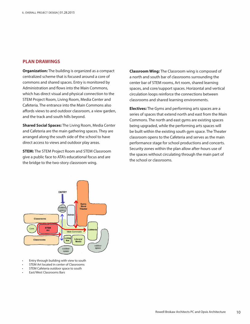
PLAN DRAWINGS
Organization: The building is organized as a compact centralized scheme that is focused around a core of commons and shared spaces. Entry is monitored by Administration and flows into the Main Commons, which has direct visual and physical connection to the STEM Project Room, Living Room, Media Center and Cafeteria. The entrance into the Main Commons also affords views to and outdoor classroom, a view garden, and the track and south hills beyond.
Shared Social Spaces: The Living Room, Media Center and Cafeteria are the main gathering spaces. They are arranged along the south side of the school to have direct access to views and outdoor play areas.
STEM: The STEM Project Room and STEM Classroom give a public face to ATA’s educational focus and are the bridge to the two-story classroom wing.
Classroom Wing: The Classroom wing is composed of a north and south bar of classrooms surrounding the center bar of STEM rooms, Art room, shared learning spaces, and core/support spaces. Horizontal and vertical circulation loops reinforce the connections between classrooms and shared learning environments.
Electives: The Gyms and performing arts spaces are a series of spaces that extend north and east from the Main Commons. The north and east gyms are existing spaces being upgraded, while the performing arts spaces will be built within the existing south gym space. The Theater classroom opens to the Cafeteria and serves as the main performance stage for school productions and concerts. Security zones within the plan allow after-hours use of the spaces without circulating through the main part of the school or classrooms.
• Entry through building with view to south• STEM Art located in center of Classrooms• STEM Cafeteria outdoor space to south• East/West Classrooms Bars
10Rowell Brokaw Architects PC and Opsis Architecture
11Rowell Brokaw Architects PC and Opsis Architecture
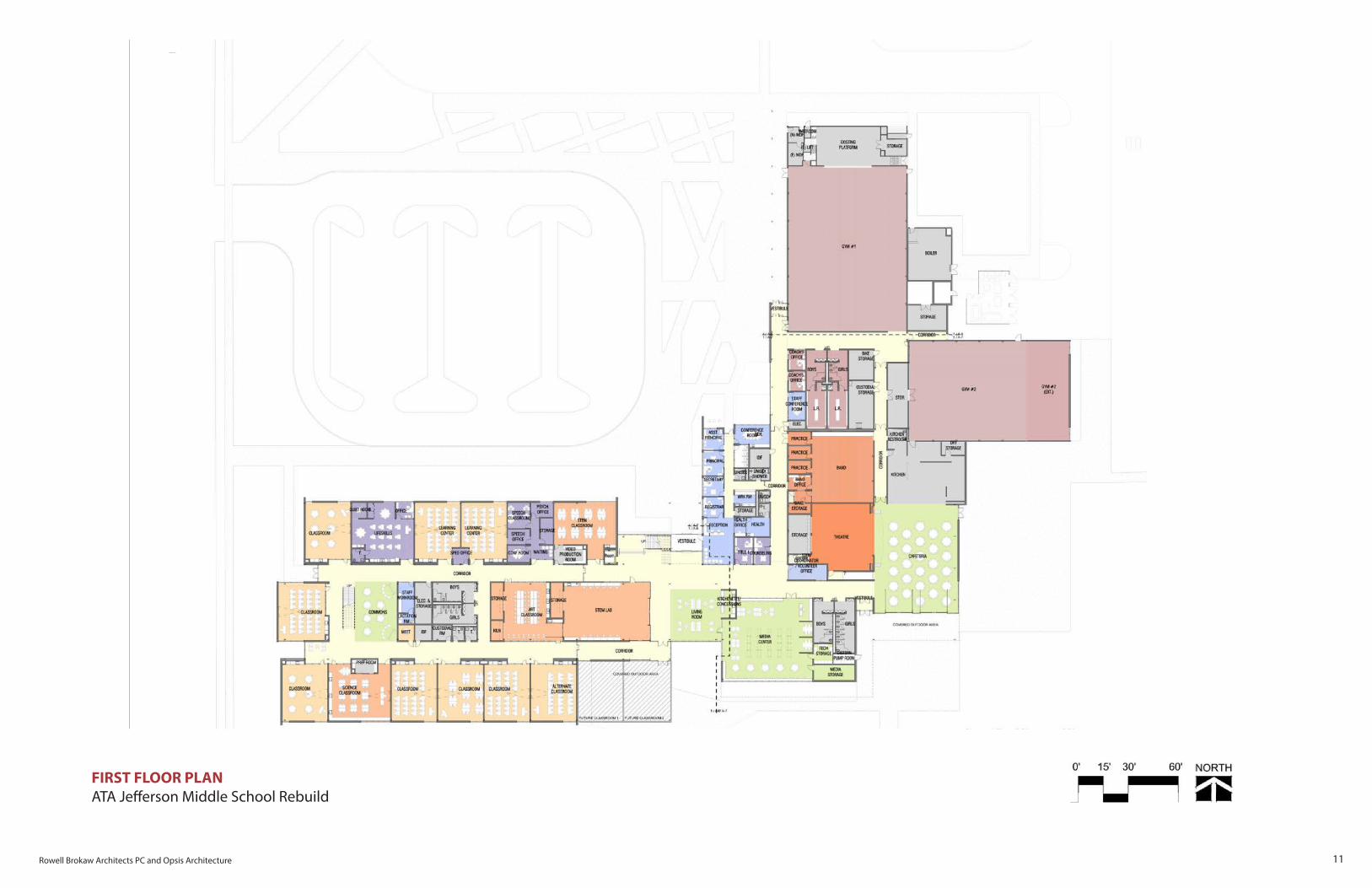
FIRST FLOOR PLANATA Jefferson Middle School Rebuild

13Rowell Brokaw Architects PC and Opsis Architecture
SECOND FLOOR PLANATA Jefferson Middle School Rebuild
15Rowell Brokaw Architects PC and Opsis Architecture
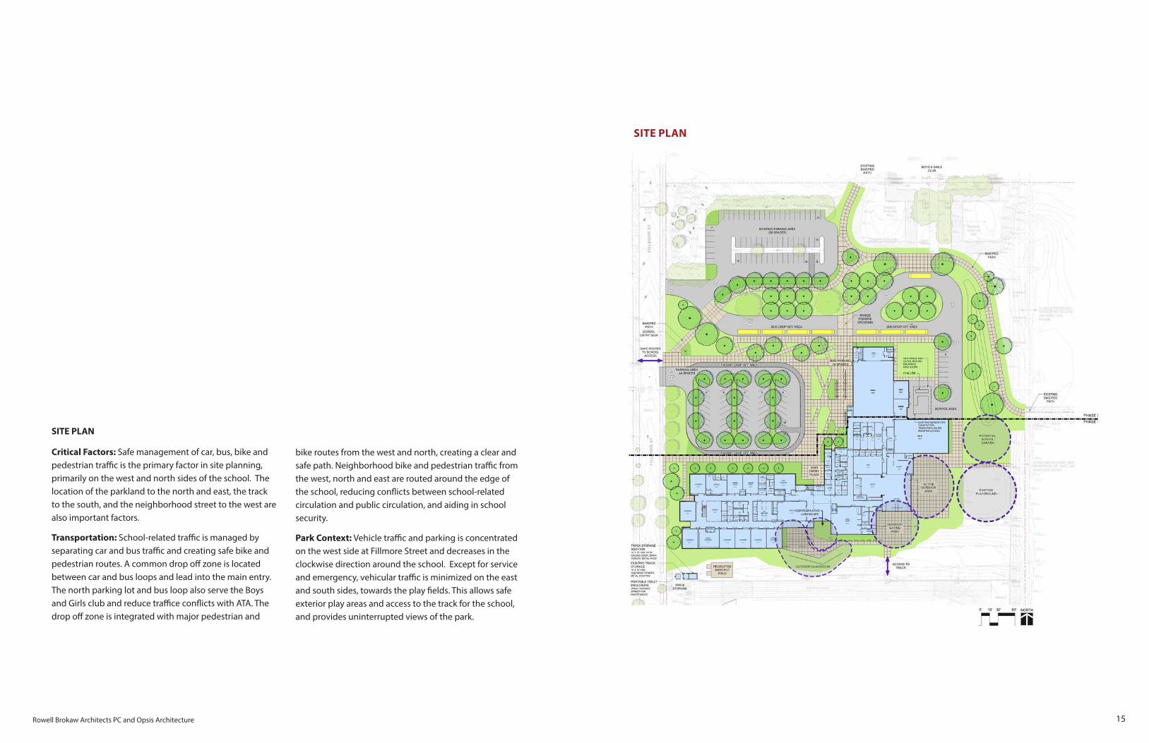
SITE PLAN
Critical Factors: Safe management of car, bus, bike and pedestrian traffic is the primary factor in site planning, primarily on the west and north sides of the school. The location of the parkland to the north and east, the track to the south, and the neighborhood street to the west are also important factors.
Transportation: School-related traffic is managed by separating car and bus traffic and creating safe bike and pedestrian routes. A common drop off zone is located between car and bus loops and lead into the main entry.The north parking lot and bus loop also serve the Boys and Girls club and reduce traffice conflicts with ATA. The drop off zone is integrated with major pedestrian and
bike routes from the west and north, creating a clear and safe path. Neighborhood bike and pedestrian traffic from the west, north and east are routed around the edge of the school, reducing conflicts between school-related circulation and public circulation, and aiding in school security.
Park Context: Vehicle traffic and parking is concentrated on the west side at Fillmore Street and decreases in the clockwise direction around the school. Except for service and emergency, vehicular traffic is minimized on the east and south sides, towards the play fields. This allows safe exterior play areas and access to the track for the school, and provides uninterrupted views of the park.
SITE PLAN

17Rowell Brokaw Architects PC and Opsis Architecture
ata jefferson middle school | eugene district 4j | schematic design report
Massing Diagram
BUILDING FORM AND CHARACTER
Basic building form and architectural character direction were determined in schematic design, and will continue to evolve in design development. The main form of the building reflects the major parts of the school. The most dominant part is the 2-story STEM/Art/Commons core, straddled by lower volumes of the north and south classroom bars. A 1-story administration and circulation structure leads to the main entry and provides a scaled foreground to the tall volumes of the existing gyms. Higher, 1-story volumes open to the south fields, and contain social spaces such as the cafeteria, media center and living room.
Materials such as brick and wood will allow the building to be grounded and approachable. Exposed structure and building systems will display how the building works and support the STEM focused curriculum. Thoughtful placement of interior and exterior windows provide daylight and views to encourage community within the ATA population and provide connection to the surrounding neighborhood.

18 Rowell Brokaw Architects PC and Opsis Architecture
ii. overall project design | 01.28.2015
Axonometric View from Northwest
Axonometric View from Southwest

19Rowell Brokaw Architects PC and Opsis Architecture
ata jefferson middle school | eugene district 4j | schematic design report
Context View from Track (Southeast)
Context View from Fillmore St. (Northwest)

20 Rowell Brokaw Architects PC and Opsis Architecture
ii. overall project design | 01.28.2015
View towards Main Entry
View towards Outdoor Classroom, Living Room and Media Center
21Rowell Brokaw Architects PC and Opsis Architecture
ata jefferson middle school | eugene district 4j | schematic design report
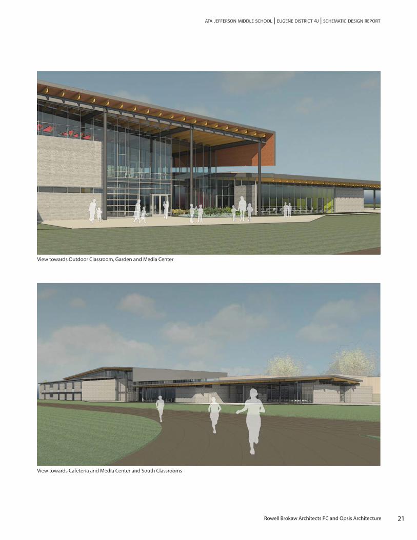
View towards Outdoor Classroom, Garden and Media Center
View towards Cafeteria and Media Center and South Classrooms

23Rowell Brokaw Architects PC and Opsis Architecture
ata jefferson middle school | eugene district 4j | schematic design report
SCHEDULE + PHASING
Design: July 2014 – February 2015
Phase 1 Construction: Spring/Summer 2016 – Summer 2017 (Completed for September 2017)
Phase 2 Construction: Summer 2017 – Fall/Winter 2017 (Completed for January 2018)
OVERVIEW
Construction of the ATA Rebuild is scheduled to begin in Spring/Summer of 2016, with completion projected for Winter 2017. The project will be bid as a single package in February/March of 2016. The school will remain in operation throughout construction, so the selected contractor will need to build the project in two phases. Refer to phasing plans for areas of construction.
GRAPHIC SCHEDULE

24 Rowell Brokaw Architects PC and Opsis Architecture
iii. schedule and phasing | 01.28.2015
PHASING DIAGRAMS
Phase 1: June 2016 to August 2017
• Install construction fencing and barriers, and construction access to separate school operations from construction activities
• Demolish south portion of existing building and adjacent site• Install Owner-furnished modular classrooms in the northeast corner of the site. Provide
foundations, power, data, alarm and plumbing connections• Maintain utility service and building systems to remaining occupied building• Install new site utilities• Construct new building• Remodel Gym #3 into Band/Theater• Addition to Gym #2• Addition to Track Storage Building, Relocation of Shot Put field• Complete sitework in area of construction

25Rowell Brokaw Architects PC and Opsis Architecture
ata jefferson middle school | eugene district 4j | schematic design report
Phase 2: June 2017 to November 2017
• Phase 1 and Phase 2 overlap during 4J Summer break• Re-locate construction fencing and barriers, and construction access to separate school
operations from construction activities• Demolish remainder of existing building and adjacent site, except north parking• Remove modular classrooms. Relocate as directed by 4J• June 2017–August 2017 (Summer Break): Change over and replace main mechanical and
electrical equipment for new building to operate for Fall Term• Remodel Main Gym

27Rowell Brokaw Architects PC and Opsis Architecture
ata jefferson middle school | eugene district 4j | schematic design report
BUILDING SPACE PROGRAM
29Rowell Brokaw Architects PC and Opsis Architecture
ata jefferson middle school | eugene district 4j | schematic design report
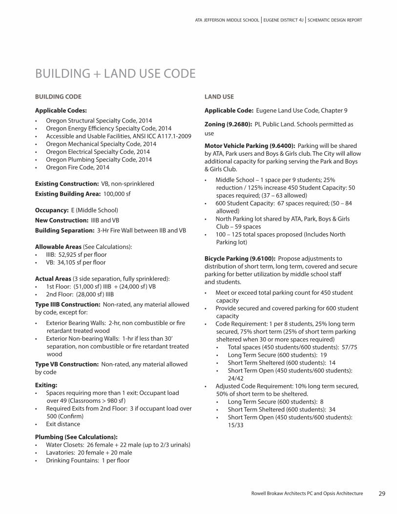
BUILDING + LAND USE CODE
BUILDING CODE
Applicable Codes:
• Oregon Structural Specialty Code, 2014• Oregon Energy Efficiency Specialty Code, 2014• Accessible and Usable Facilities, ANSI ICC A117.1-2009• Oregon Mechanical Specialty Code, 2014• Oregon Electrical Specialty Code, 2014• Oregon Plumbing Specialty Code, 2014• Oregon Fire Code, 2014
Existing Construction: VB, non-sprinklered
Existing Building Area: 100,000 sf
Occupancy: E (Middle School)
New Construction: IIIB and VB
Building Separation: 3-Hr Fire Wall between IIB and VB
Allowable Areas (See Calculations):• IIIB: 52,925 sf per floor• VB: 34,105 sf per floor
Actual Areas (3 side separation, fully sprinklered):• 1st Floor: (51,000 sf ) IIIB + (24,000 sf ) VB• 2nd Floor: (28,000 sf ) IIIB
Type IIIB Construction: Non-rated, any material allowed by code, except for:
• Exterior Bearing Walls: 2-hr, non combustible or fire retardant treated wood
• Exterior Non-bearing Walls: 1-hr if less than 30’ separation, non combustible or fire retardant treated wood
Type VB Construction: Non-rated, any material allowed by code
Exiting:• Spaces requiring more than 1 exit: Occupant load
over 49 (Classrooms > 980 sf )• Required Exits from 2nd Floor: 3 if occupant load over
500 (Confirm)• Exit distance
Plumbing (See Calculations):• Water Closets: 26 female + 22 male (up to 2/3 urinals)• Lavatories: 20 female + 20 male• Drinking Fountains: 1 per floor
LAND USE
Applicable Code: Eugene Land Use Code, Chapter 9
Zoning (9.2680): PL Public Land. Schools permitted as use
Motor Vehicle Parking (9.6400): Parking will be shared by ATA, Park users and Boys & Girls club. The City will allow additional capacity for parking serving the Park and Boys & Girls Club.
• Middle School – 1 space per 9 students; 25% reduction / 125% increase 450 Student Capacity: 50 spaces required; (37 – 63 allowed)
• 600 Student Capacity: 67 spaces required; (50 – 84 allowed)
• North Parking lot shared by ATA, Park, Boys & Girls Club – 59 spaces
• 100 – 125 total spaces proposed (Includes North Parking lot)
Bicycle Parking (9.6100): Propose adjustments to distribution of short term, long term, covered and secure parking for better utilization by middle school staff and students.
• Meet or exceed total parking count for 450 student capacity
• Provide secured and covered parking for 600 student capacity
• Code Requirement: 1 per 8 students, 25% long term secured, 75% short term (25% of short term parking sheltered when 30 or more spaces required)• Total spaces (450 students/600 students): 57/75• Long Term Secure (600 students): 19• Short Term Sheltered (600 students): 14• Short Term Open (450 students/600 students): 24/42
• Adjusted Code Requirement: 10% long term secured, 50% of short term to be sheltered.• Long Term Secure (600 students): 8• Short Term Sheltered (600 students): 34• Short Term Open (450 students/600 students): 15/33

30 Rowell Brokaw Architects PC and Opsis Architecture
v. building and land use code | 01.28.2015
CODE ANALYSIS

31Rowell Brokaw Architects PC and Opsis Architecture
ata jefferson middle school | eugene district 4j | schematic design report
OUTLINE SPECIFICATION
DIVISION 0 – PROCUREMENT AND CONTRACTING REQUIREMENTS
DIVISION 1 – GENERAL REQUIREMENTS
01 2300 Alternates
Alternate 1: Delete (2) Alternate Classrooms at south side, between Grids J & L, and Grids 8 & 9. Wall along Grid L to be 50% glazing and 50% brick veneer.
Alternate 2: Delete extension of Gym #2. Maintain replacement of mechanical and electrical system for the existing gym.
Alternate 3: Delete re-surfacing of existing parking lot at the Northwest corner of the site.
Alternate 4: Delete pumps and filtration equipment for Rainwater Harvest system. Pipes and cistern to remain in scope.
DIVISION 2 – EXISTING CONDITIONS
DIVISION 3 – CONCRETE
03 3000 Cast-in-Place Concrete: See structural drawings and notes for depths of slabs.
03 3511 Concrete Floor Finishes: Ground and polished concrete where indicated on floor finish plans; gray; 800 grit.
03 4500 Precast Architectural Concrete: Stair treads; gray, acid washed.
DIVISION 4 – MASONRY
04 2000 Unit Masonry: 8 x 8 x16 reinforced CMU block at Track Storage Addition, Gym 2 Addition, Misc. wall infill; smooth finish; gray.
04 2001 Masonry Veneer: Clay brick with seismic veneer anchors; running bond.
Division 5 – Metals
05 1200 Structural Steel Framing: See structural drawings and notes. Galvanize and all exposed exterior members. Field paint all interior and exterior exposed steel.
05 3100 Steel Decking: Composite at floors, non-composite at roof.
05 4000 Cold-Formed Metal Framing: Provide at exterior wall framing.
05 5000 Metal Fabrications• Steel Sunshades: Budget for 3’ deep x 2/3 length of
south Classroom walls at 1st floor. Steel grating on steel plate supports. Custom designed and fabricated at south walls. Galvanized and paint.
• Roof ladder and ships ladder: Galvanize and paint• Downspouts: Galvanize and paint.• Include allowance for misc. fabrications: veneer lintels
05 5113 Metal Stairs: Steel Frame Stairs with precast concrete treads at both stairways; shop primed, field finished.
05 5200 Metal Railings: Steel balcony and stair railing systems: 2” x ½” steel bar frames with mesh infill. Powder coat or field paint.
DIVISION 6 – WOOD, PLASTICS AND COMPOSITES
06 1000 Rough Carpentry: • Wall framing at Administration. Exterior wall framing
to be fire retardant treated.

32 Rowell Brokaw Architects PC and Opsis Architecture
vi. outline specification | 01.28.2015
• Plywood roof sheathing over wood decking. • Allowance for miscellanous wood framing and
blocking.
06 1500 Wood Decking: 3x6 T&G roof decking; clear douglas fir; transparent finish.
06 1733 Wood I-Joists: Use at Administration roof structure
06 1800 Glued-Laminated Construction: Roof beams and joists. AITC Premium Grade.
06 2000 Finish Carpentry: White oak, rift sawn, typical.• Wood base and trim at Living Room and Media Center.• Wood trim and wall panels at Lobby and Kitchen/
Concesion/Living Room.• Solid surface panel wainscot at main hallways.
06 4100 Casework:• Plastic Laminate cabinets with plastic laminate
countertops typical.• Wood veneer cabinets at Reception area and Kitchen/
Concession. White Oak, rift sawn.• Quartz composite countertops at Reception, Kitchen/
Concession and Breakroom counters with sinks.• Epoxy resin countertops at Science Classrooms
DIVISION 7 – THERMAL AND MOISTURE PROTECTION
07 1113 Bituminous Dampproofing: At above-grade planters and patching at existing tunnels.
07 1713 Bentonite Panel Waterproofing: At elevator pit. – Tremco Paraseal HPDE.
07 1900 Water Repellents: At all exterior and interior exposed masonry and concrete vertical surfaces, and non-traffic horizontal surfaces. Protectosil Chem-Trete 40 VOC by Evonik.• Anti-graffiti coating at 1st story of exterior masonry
walls.
07 2100 Thermal Insulation:• Walls: Continuous 3” Mineral Board – Roxul Cavity
Rock; Roof: R-30 Polyisocyanurate.• Acoustical insulation at walls: unfaced sound
insulation to fill cavity.
07 2500 Weather Resistant Barriers: Blueskin SA air, water and vapor barrier. Apply over exterior wall sheathing and roof sheathing where metal roofing will be installed.
07 4113 Metal Roof Panels: Low slope application to ¼”:12”; mechanically sealed standing seams. AEP Span Span-Lok hp;
07 4213 Metal Wall Panels: AEP Span 12” Prestige, vertical orientation, plus trims.
07 4645 Fiber Cement Siding: SwissPearl, integral color, with rainscreen attachment system.
07 5100 Membrane Roofing: Scarnfil, Energy Smart G410; IB Roof Systems, CPA single-ply; Versico, Versiflex, 80 mil. PVC. Warranty: 20-year. Fully adhered system. Provide coverboard over insulation.
07 6200 Flashing and Sheet Metal: Pre-coated galvanized steel: ASTM A525 G90 or Galvalume, 24-gauge, shop pre-coated with Kynar 500 flourocarbon resin coating of selected color. Gutters, flashings.
• Stainless steel flashing at brick veneer.
07 7200 Roof Accessories: Roof Hatches
07 8123 Intumescent Mastic Fireproofing: Budget for incidental steel framing concealed in exterior walls. Most framing is interior of perimeter wall.
07 8400 Penetration Firestopping: Budget.

33Rowell Brokaw Architects PC and Opsis Architecture
ata jefferson middle school | eugene district 4j | schematic design report
07 9005 Joint Sealers: Budget.
07 9513 Expansion Joint Cover Assemblies: Wall and roof covers at seismic joint between the main 2-story structure and the Lobby/Admin/Media Center structure.
DIVISION 8 – OPENINGS
08 1113 Hollow Metal Doors and Frames:• All door frames 16 ga. hollow metal except at
aluminum storefront and curtainwall. Galvanized at exterior openings.
• Exterior Service Doors: Painted galvanized Hollow metal. Glass lites insulated and tempered where required.
• Interior Service Doors: Painted hollow metal.• Corridor Doors: Painted Hollow metal on hold open.
90 min. doors at Building Separation (3-hr Fire Wall).
08 1416 Flush Wood Doors:• Solid core, factory clear finish wood veneer flush doors
with wood frame. White oak, rift sawn. • Glass lites tempered where required.
08 3100 Access Doors and Panels: Drywall bead frame with door surface flush with wall surface, paint to match wall.• Stainless steel at restrooms, locker rooms, kitchens.
08 3326 Overhead Coiling Grilles: At cafeteria/kitchen service counter – Aluminum horizontal bar curtain. Electric operation.
08 3613 Sectional Doors: Stile and rail aluminum with glazed panels, high vertical lift operation. Insulated glazing at exterior doors. Electric operation.
08 4229 Automatic Entrances• All-glass sliding automatic door assembly at Main
Entry Vestibule (both sets of doors): Tormax. Finish to match adjacent storefront or curtainwall.
• ADA operators for Exterior Swinging Doors: At Gym and Cafeteria Vestibules, and West entry door.
08 4313 Storefronts: Aluminum anodized (clear) storefront system• Exterior: Kawneer 451T typical. Insulated low-e
glazing (Solarban 60). Kawneer 500 Heavy Wall doors.• Interior: Kawneer VG 450. Single glazing typical.
Insulated glazing where noted for acoustical walls. Kawneer 350 Medium Style doors.
08 4413 Glazed Aluminum Curtain Walls: Kawneer 1600UT System 1.• Use at self-supporting exterior glazing systems taller
than 12’.• Glazing and doors similar to Storefront system.
08 6300 Metal-Framed Skylights: Factory fabricated aluminum framed. DeaMor.• Insulated glazing with fritted pattern.
08 7100 Door Hardware: 4J Standards:• Locksets: Schlage “Rhodes” ND 93, ND96, ND53.
US626D• Exit Devices: Von Duprin Rim, IC Core, P.H.I. on all
vertical rod applications, IC Core. All vertical rods to be surface mounted and trhru bolted. No concealed vertical rods.
• Closers: LCN 4010/4111DEL, with WMS screw packs.• Flush bolts: Ives• Exit Devices for Card Access Security Doors: Active
Side – Von Duprin EL98NL-LD US26D; Off Side – Von Duprin 98EO-LD US26D with 99EO trim. Power Supply – Von Duprin PS914-4RL-BB-KL. Electric Power Transfer – Securitron SEPT
• Magnetic hold opens
34 Rowell Brokaw Architects PC and Opsis Architecture
vi. outline specification | 01.28.2015
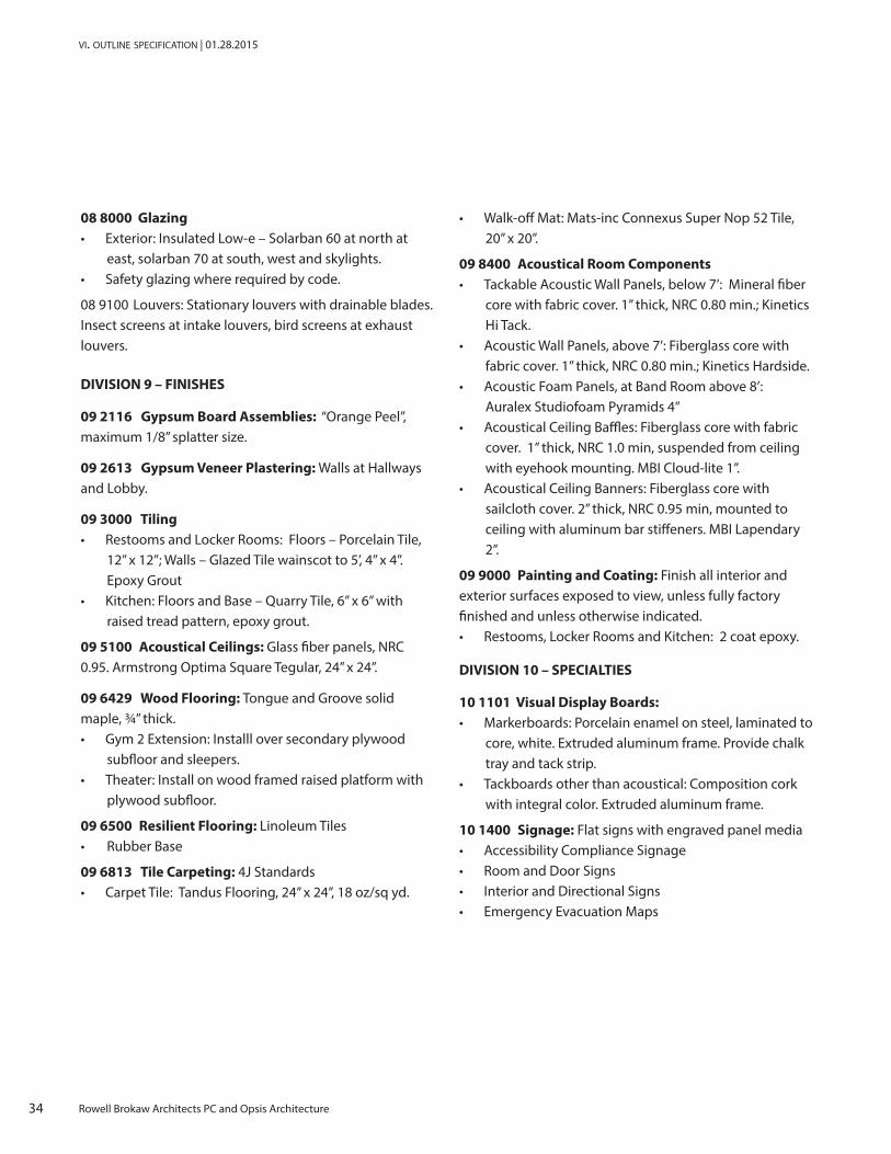
08 8000 Glazing• Exterior: Insulated Low-e – Solarban 60 at north at
east, solarban 70 at south, west and skylights.• Safety glazing where required by code.
08 9100 Louvers: Stationary louvers with drainable blades. Insect screens at intake louvers, bird screens at exhaust louvers.
DIVISION 9 – FINISHES
09 2116 Gypsum Board Assemblies: “Orange Peel”, maximum 1/8” splatter size.
09 2613 Gypsum Veneer Plastering: Walls at Hallways and Lobby.
09 3000 Tiling• Restooms and Locker Rooms: Floors – Porcelain Tile,
12” x 12”; Walls – Glazed Tile wainscot to 5’, 4” x 4”. Epoxy Grout
• Kitchen: Floors and Base – Quarry Tile, 6” x 6” with raised tread pattern, epoxy grout.
09 5100 Acoustical Ceilings: Glass fiber panels, NRC 0.95. Armstrong Optima Square Tegular, 24” x 24”.
09 6429 Wood Flooring: Tongue and Groove solid maple, ¾” thick.• Gym 2 Extension: Installl over secondary plywood
subfloor and sleepers.• Theater: Install on wood framed raised platform with
plywood subfloor.
09 6500 Resilient Flooring: Linoleum Tiles• Rubber Base
09 6813 Tile Carpeting: 4J Standards• Carpet Tile: Tandus Flooring, 24” x 24”, 18 oz/sq yd.
• Walk-off Mat: Mats-inc Connexus Super Nop 52 Tile, 20” x 20”.
09 8400 Acoustical Room Components• Tackable Acoustic Wall Panels, below 7’: Mineral fiber
core with fabric cover. 1” thick, NRC 0.80 min.; Kinetics Hi Tack.
• Acoustic Wall Panels, above 7’: Fiberglass core with fabric cover. 1” thick, NRC 0.80 min.; Kinetics Hardside.
• Acoustic Foam Panels, at Band Room above 8’: Auralex Studiofoam Pyramids 4”
• Acoustical Ceiling Baffles: Fiberglass core with fabric cover. 1” thick, NRC 1.0 min, suspended from ceiling with eyehook mounting. MBI Cloud-lite 1”.
• Acoustical Ceiling Banners: Fiberglass core with sailcloth cover. 2” thick, NRC 0.95 min, mounted to ceiling with aluminum bar stiffeners. MBI Lapendary 2”.
09 9000 Painting and Coating: Finish all interior and exterior surfaces exposed to view, unless fully factory finished and unless otherwise indicated.• Restooms, Locker Rooms and Kitchen: 2 coat epoxy.
DIVISION 10 – SPECIALTIES
10 1101 Visual Display Boards:• Markerboards: Porcelain enamel on steel, laminated to
core, white. Extruded aluminum frame. Provide chalk tray and tack strip.
• Tackboards other than acoustical: Composition cork with integral color. Extruded aluminum frame.
10 1400 Signage: Flat signs with engraved panel media• Accessibility Compliance Signage• Room and Door Signs• Interior and Directional Signs• Emergency Evacuation Maps
35Rowell Brokaw Architects PC and Opsis Architecture
ata jefferson middle school | eugene district 4j | schematic design report
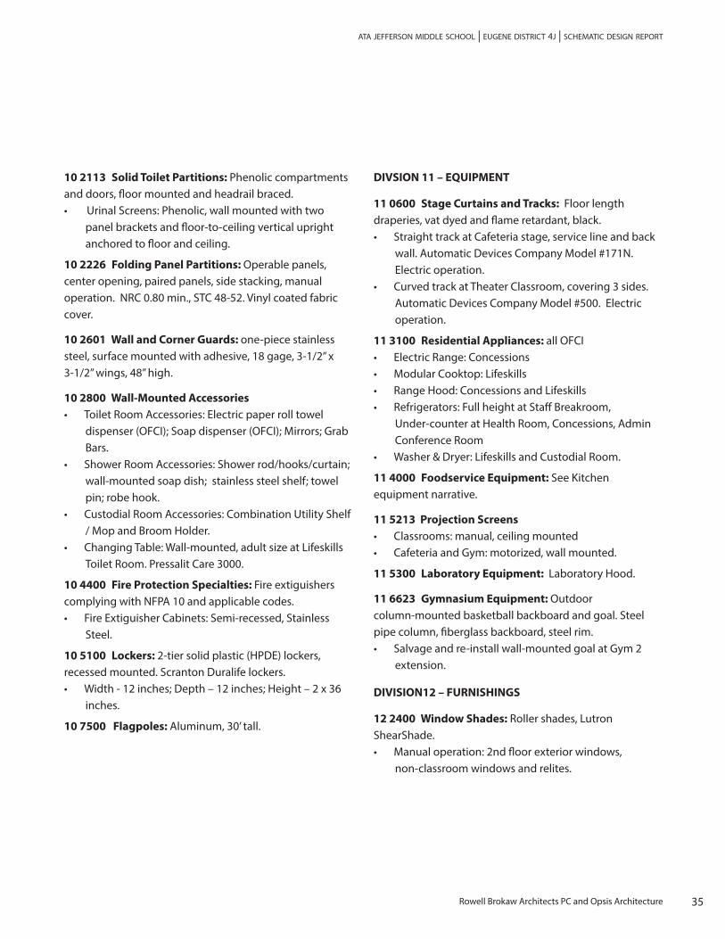
10 2113 Solid Toilet Partitions: Phenolic compartments and doors, floor mounted and headrail braced.• Urinal Screens: Phenolic, wall mounted with two
panel brackets and floor-to-ceiling vertical upright anchored to floor and ceiling.
10 2226 Folding Panel Partitions: Operable panels, center opening, paired panels, side stacking, manual operation. NRC 0.80 min., STC 48-52. Vinyl coated fabric cover.
10 2601 Wall and Corner Guards: one-piece stainless steel, surface mounted with adhesive, 18 gage, 3-1/2” x 3-1/2” wings, 48” high.
10 2800 Wall-Mounted Accessories• Toilet Room Accessories: Electric paper roll towel
dispenser (OFCI); Soap dispenser (OFCI); Mirrors; Grab Bars.
• Shower Room Accessories: Shower rod/hooks/curtain; wall-mounted soap dish; stainless steel shelf; towel pin; robe hook.
• Custodial Room Accessories: Combination Utility Shelf / Mop and Broom Holder.
• Changing Table: Wall-mounted, adult size at Lifeskills Toilet Room. Pressalit Care 3000.
10 4400 Fire Protection Specialties: Fire extiguishers complying with NFPA 10 and applicable codes.• Fire Extiguisher Cabinets: Semi-recessed, Stainless
Steel.
10 5100 Lockers: 2-tier solid plastic (HPDE) lockers, recessed mounted. Scranton Duralife lockers.• Width - 12 inches; Depth – 12 inches; Height – 2 x 36
inches.
10 7500 Flagpoles: Aluminum, 30’ tall.
DIVSION 11 – EQUIPMENT
11 0600 Stage Curtains and Tracks: Floor length draperies, vat dyed and flame retardant, black.• Straight track at Cafeteria stage, service line and back
wall. Automatic Devices Company Model #171N. Electric operation.
• Curved track at Theater Classroom, covering 3 sides. Automatic Devices Company Model #500. Electric operation.
11 3100 Residential Appliances: all OFCI• Electric Range: Concessions• Modular Cooktop: Lifeskills• Range Hood: Concessions and Lifeskills• Refrigerators: Full height at Staff Breakroom,
Under-counter at Health Room, Concessions, Admin Conference Room
• Washer & Dryer: Lifeskills and Custodial Room.
11 4000 Foodservice Equipment: See Kitchen equipment narrative.
11 5213 Projection Screens• Classrooms: manual, ceiling mounted• Cafeteria and Gym: motorized, wall mounted.
11 5300 Laboratory Equipment: Laboratory Hood.
11 6623 Gymnasium Equipment: Outdoor column-mounted basketball backboard and goal. Steel pipe column, fiberglass backboard, steel rim.• Salvage and re-install wall-mounted goal at Gym 2
extension.
DIVISION12 – FURNISHINGS
12 2400 Window Shades: Roller shades, Lutron ShearShade. • Manual operation: 2nd floor exterior windows,
non-classroom windows and relites.
36 Rowell Brokaw Architects PC and Opsis Architecture
vi. outline specification | 01.28.2015
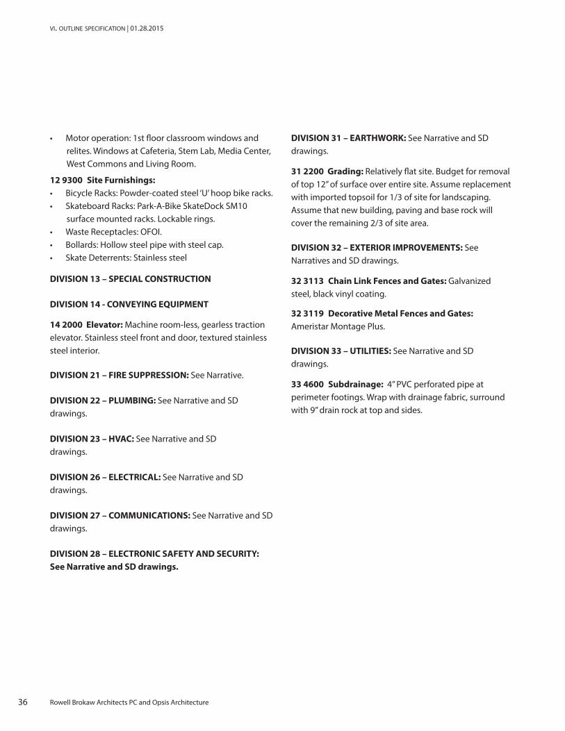
• Motor operation: 1st floor classroom windows and relites. Windows at Cafeteria, Stem Lab, Media Center, West Commons and Living Room.
12 9300 Site Furnishings:• Bicycle Racks: Powder-coated steel ‘U’ hoop bike racks.• Skateboard Racks: Park-A-Bike SkateDock SM10
surface mounted racks. Lockable rings.• Waste Receptacles: OFOI.• Bollards: Hollow steel pipe with steel cap.• Skate Deterrents: Stainless steel
DIVISION 13 – SPECIAL CONSTRUCTION
DIVISION 14 - CONVEYING EQUIPMENT
14 2000 Elevator: Machine room-less, gearless traction elevator. Stainless steel front and door, textured stainless steel interior.
DIVISION 21 – FIRE SUPPRESSION: See Narrative.
DIVISION 22 – PLUMBING: See Narrative and SD drawings.
DIVISION 23 – HVAC: See Narrative and SD drawings.
DIVISION 26 – ELECTRICAL: See Narrative and SD drawings.
DIVISION 27 – COMMUNICATIONS: See Narrative and SD drawings.
DIVISION 28 – ELECTRONIC SAFETY AND SECURITY: See Narrative and SD drawings.
DIVISION 31 – EARTHWORK: See Narrative and SD drawings.
31 2200 Grading: Relatively flat site. Budget for removal of top 12” of surface over entire site. Assume replacement with imported topsoil for 1/3 of site for landscaping. Assume that new building, paving and base rock will cover the remaining 2/3 of site area.
DIVISION 32 – EXTERIOR IMPROVEMENTS: See Narratives and SD drawings.
32 3113 Chain Link Fences and Gates: Galvanized steel, black vinyl coating.
32 3119 Decorative Metal Fences and Gates: Ameristar Montage Plus.
DIVISION 33 – UTILITIES: See Narrative and SD drawings.
33 4600 Subdrainage: 4” PVC perforated pipe at perimeter footings. Wrap with drainage fabric, surround with 9” drain rock at top and sides.
37Rowell Brokaw Architects PC and Opsis Architecture
ata jefferson middle school | eugene district 4j | schematic design report
PROJECT SYSTEMS NARRATIVES
CIVIL NARRATIVE
SITE PAVING
The pavement design is not complete. The pavement design is based on the geotechnical report and the geotechnical report has not been issued. The following pavement sections can be used for general pricing at this phase of the project; however the designs will most likely change based on the final geotechnical report. The proposed pavement sections are as follows:
• Parking Areas: 3” AC over 11” of base rock• Bus Loop, Driveways, and Trash Area: 4” AC over 15” of
base rock• Active Outdoor Play Areas: 3” AC over 11” of base rock• Outdoor Classroom and Eating Areas: 6” of
unreinforced PCC over 4” of base rock• Concrete Pavement: 8” plain doweled PCC over 10” of
base rock
The sidewalks will be designed and built per the 4J standards, which require 6” of reinforced PCC over 4” of base rock, however the sidewalk can be reduced to 4” of unreinforced concrete if the District accepts the variation from their standard.
The existing northwest parking lot will not be replaced. This parking lot will either be overlaid with a single 1.5-inch lift of AC or a bituminous slurry will be applied to the existing pavement.
UTILITIES
Domestic Water and Fire Protection
The existing school is served by a 3-inch metered domestic water service at 22nd Avenue. The water service includes a backflow prevention device in an underground exterior vault. The existing school is not sprinklered. EWEB has an existing 6-inch water main in the west side of Fillmore Street and an 8-inch on the south side of 22nd Avenue.
The new school will most likely require a new 4-inch water service, meter and exterior backflow, and a new 6-inch fire protection serve and exterior double detector check assembly. The new water services will require a 6 to 8-inch tap to the existing public 8-inch main in Fillmore. In addition, a new fire hydrant may be required at the east side of the school, which will require a new tap to the public 8-inch main in Fillmore Street. According to EWEB there are no known deficiencies in the existing water system, and there is most likely sufficient water pressure and flow to adequately serve the proposed school with both domestic and fire protection water.
Sanitary Sewer
The existing school is served by the 8-inch main in Fillmore Street. In addition, there is an existing public 30-inch sanitary sewer main that runs south to north along the east side of the existing school in an easement.

38 Rowell Brokaw Architects PC and Opsis Architecture
vii. project systems narratives | 01.28.2015
The proposed school project will most likely be able to use the existing 8-inch main in Fillmore Street and the existing 8-inch pipe on the site. The existing 8-inch main most likely has capacity to serve the new school.
It is anticipated that a second sanitary sewer service will be required. The new kitchen is located on the east side of the proposed building and will require an exterior grease interceptor. The grease interceptor will most likely be located on the east side of the building and will discharge to the existing 30-inch main. The new service connection can be made either with a new or to an existing manhole, or by coring directly into the existing main with a new service lateral. The 30-inch sanitary main is between 15 and 18 feet deep. According to the City of Eugene’s sanitary sewer master plan, there are no known deficiencies in this existing main and it will adequately serve the proposed school.
Storm Drainage
The storm drainage from the existing school and site is currently conveyed in a 10-inch pipe that runs south-to-north along the east side of the existing school and ultimately disposed of in drywells north of the existing school, between the school and the Boys and Girls Club building. Documentation on the existing drywells appears to be unavailable, and the capacity of the existing drywells is unknown. In addition, some of the existing building and site area is discharged to grassy areas around the perimeter of the school and infiltrated within those landscape areas. There are three existing large-diameter south-to-north running public storm drainage mains to the east of the existing school site; a 66-inch main, a 60-inch main and a 48-inch main.
Future disposal of the new school and site drainage to the existing drywells is not recommended. The existing
drywells are not registered UIC devises with Oregon DEQ and do not meet current requirements. A new connection to the existing 66-inch diameter main is recommended and will be allowed by the city. The connection can be made either with a new or existing manhole or by coring directly into the existing main with a new service lateral.
Stormwater Quality
As of March 1, 2014, new stormwater requirements and code are in effect for the City of Eugene. The new requirements implement a hierarchy of treatment:
1. If a site has infiltration rates higher than 2”/hour, a vegetated infiltration facility is required.
2. If infiltration is impossible because the infiltration rates are too low, a vegetated filtration facility is required.
3. If there is insufficient space on site for vegetated treatment, the stormwater SDC fees will be raised from $0.20 per square foot of new or redeveloped impervious surface to $1.88 per square foot of impervious surface. In order to prove there is insufficient space on site, the most space-efficient stormwater facility must be sized, and the designer must show that there is less open space on site than the required size of the stormwater facility.
4. If there is insufficient space on site for vegetated treatment, the developer may elect to install an approved proprietary mechanical treatment device. Doing mechanical treatment will lower the SDC fee to approximately $1.00 per square foot of impervious surface.
Under this hierarchy, the proposed development site will need to include stormwater filtration facilities. The current design includes approximately 10,000 square feet of
39Rowell Brokaw Architects PC and Opsis Architecture
ata jefferson middle school | eugene district 4j | schematic design report
treatment facilities. Approximately one third of that area will be grassy swales and the remainder will be filtration rain gardens.
To the extent possible, the new school site development will include vegetated stormwater treatment facilities throughout the site that will treat the roof and site runoff prior to conveyance and disposal to the public storm drainage facilities. Vegetated treatment will most likely include several types of landscape facilities, such as rain gardens, infiltration and filtration planters, swales and filter strips.
Rainwater Harvesting
If a rainwater harvesting system is pursued, it will most likely collect all or most of the rainwater from new building roof. Separate site piping will be required to collect the roof drainage, which will be conveyed through an approved pre-treatment manhole and to an underground storage tank (approximately 15,000 gallons). From the storage tanks, the collected rainwater will be pumped into the building, where it will be treated and pumped throughout the building for greywater uses. The pump controller, alarm and power will be located inside the building. Overflow from the rainwater harvesting cistern will be conveyed to either an open drainage to the east or piped directly the existing 66-inch public main to the east.
Electrical Power
EWEB has an existing overhead power line on the north side of 24th Avenue that is a 12kV three-phase high-capacity feeder. EWEB has a second distribution from an existing 12kV overhead power feeder from 22nd Avenue that crosses Polk Street and goes west to a vault near the existing school. It serves the existing school, the lighting for the two baseball fields, pathway lighting, the
Boys and Girls Club building, and the Kid’s Sports building. There is no existing electrical power distribution on Polk Street.
The existing overhead feeder on 22nd Avenue is most likely adequate to serve the proposed school. Undergrounding any existing overhead services is desired. Any new or existing electrical services within the new school site will be placed underground.
Fiber
EWEB current provides fiber serve to the existing school from 22nd Avenue at Fillmore Street. The 4J School District uses EWEB commercialized fiber distribution to provide fiber links between District facilities. It is anticipated that the new school will continue to use EWEB fiber and that the existing service is adequate to service the new school.
40 Rowell Brokaw Architects PC and Opsis Architecture
vii. project systems narratives | 01.28.2015
SITE AND LANDSCAPE NARRATIVE
General Approach
The site development for this project will comply with School District 4J standards, and the City of Eugene standards for development. Input and direction from District representatives is also represented in the site development to date.
General Site Design
The primary approach to building entries and access accommodate a finish floor elevation at a single level. The main entrance (primary) located on the north side of the building will be accessed from the intersection of Fillmore St and 22nd Ave, and is set at approximately 430.00’ +/-. All walkways shall be universally accessible and will not require landings or handrails (except where specifically noted). All sidewalks are proposed to be concrete surface. A majority of the walks will be standard gray with broom finish. Portions of walks at entries and outdoor gathering spaces may incorporate pigment or specialty finish (sand or exposed aggregate). Pedestrian walks that are to receive vehicle traffic will have a thicker profile.
Although not anticipated, any new exterior stairs will be CIP concrete with metal handrails. The typical rise / run of exterior stairs will be 6” rise / 14” tread depth. Formed CIP curbs will be used at the perimeter of all asphalt paving. Landscape planter/seat walls and retaining walls will be formed CIP concrete. All walls shall have 4” perforated drain pipe and shall be damp proofed below the finish grade of the soil. All CIP concrete walls shall be treated with Degussa Protectosil. All walls located in public areas shall be skateboard-proof. A 12-inch wide reinforced concrete mow strip will be located where new lawns abut vertical surfaces including building walls, signs, benches
or other fixed exterior elements. Refer to Electrical for site lighting.
Grading
The existing site topography is fairly flat, with the most dramatic elevation change occurring south of the new building footprint, between the existing track and the new building. Retaining walls will be required along the south edge at the outdoor classroom to accommodate the three feet of rise from the finish floor elevation of the building to the existing track surface elevation. The new building finish floor elevation (FFE) is set at approximately 430.00’. This FFE is compatible with integration of walks that access doorways, courtyards, driveways, and parking lots. All elevations are approximate.
The general vehicle and pedestrian arrival/departure zones will be graded to keep pedestrian ways at higher elevations (i.e. ridges that are dryer) and drain toward the inside of the parking areas. The bus loop will drain toward a large grassy swale area. Site elements will generally follow the natural slopes. A number of lower site/seat walls may occur throughout the site. Aesthetic grading will occur to soften the grade changes and create visual interest.
Landscape
The landscape areas will be planted with combinations of trees, shrubs, and accent plantings. The majority of the plants will be species native to Oregon or will be native “analogue” plants: plants that are adapted to similar climatic and growing conditions to native plants. The design will accommodate the mature size of the plants and trees selected and will also allow for low ongoing maintenance requirements and reduced life cycle costs. Salvage and reuse of existing topsoil is desired for all landscape types proposed, although the feasibility of

41Rowell Brokaw Architects PC and Opsis Architecture
ata jefferson middle school | eugene district 4j | schematic design report
storage for existing soil during building construction is uncertain at this time. Placement of imported loam is the alternative. Generally the desired soil profile for plant beds is 18” and lawns are 12”. All plant beds will include a mulch layer to suppress weeds and preserve soil moisture. Lawns will utilize a Rye Grass Fescue mix seed. All landscape and lawn areas will be irrigated.
There are four main landscape types anticipated:
• Plant Beds: All plant beds shall have a minimum topsoil depth of 18” with 3” compost. All plant beds will have 3” minimum depth bark mulch. Tree plantings at parking lots to be 2.5” caliper minimum.
• New Lawns: All new lawns shall have a minimum topsoil depth of 12”. Topsoil shall be imported loam. Lawns throughout the site will be gently sloping from north to south.
• Storm Water Filtration Areas: It is anticipated several storm water filtration areas will be located on site. The main parking lot will feature at least two islands serving this function. Additional storm water filtration planters will be located around the building in locations where rainwater is discharged from the roof. These areas will have a minimum 18” topsoil with 3” of compost tilled incorporated. Decorative rock mulch will be installed at a 3” minimum depth. Decorative scuppers and drainage structures are anticipated.
• Grassy Swale: A large grassy swale will be installed to the northeast of the site, south of the Boys and Girls Club building. It will function primarily as a storm water mitigation facility, collecting runoff from the bus lane/loop. As a secondary function, this landscape will serve as a barrier discouraging direct access onto school property from the east, and will encourage pedestrian and bicycle traffic to follow the new path system. The swale will have a minimum18” topsoil with 3” of compost incorporated.
There is the potential for a school food garden to be located on site, however development of such a garden will not likely take place within the scope or time-frame of this project.
Irrigation
Site irrigation will be accomplished with an automatically controlled, underground system. It will be designed and constructed to be as efficient in terms of water usage as possible. The irrigation system will be centrally controlled using the district’s existing and established Rain Bird Maxicom system.
Parking and Drop-Off Areas
Parking is located in 3 locations and will serve as staff and visitor parking during school hours of operation and parking for community and event needs during non-school hours. The existing parking lot on site will be retained, roto-milled, and a new lift of asphalt will be installed. A parent drop-off loop will be located in the parking lot adjacent to the building. An additional small number of spaces dedicated to faculty and staff parking will be located on the east side of the building.
All parking will meet ADA requirements and be constructed of asphaltic concrete with walkways constructed from reinforced concrete. Refer to Geotechnical or Civil for paving profiles. Bus drop-off occurs to the north of the building, separate from parent drop-off. Service vehicle access will utilize the bus lane to access the service area on the east side of the building. Parking lots will serve as emergency vehicle access. Parking lot landscaping will comply with City of Eugene standards. Refer to electrical narrative for parking lot lighting.

42 Rowell Brokaw Architects PC and Opsis Architecture
vii. project systems narratives | 01.28.2015
Specific Areas of Development
Fillmore St: All new curb cuts and aprons will be constructed of concrete to meet the City of Eugene standards.
North (Main) Entry, Parent Drop-off, and South Parking Lot: There will be a concrete walk and entry plaza along drop-off zone. Assume one 30ft commercial grade aluminum flagpole and a monument type school sign, both lighted. There will be raised concrete crossings at the parking lot and drive. Provide striping and signage for (2) ADA parking spaces. Assume bike racks to accommodate 74 bikes, assume 37 hoop style racks. Bike racks to be free standing, heavy gauge steel, with powder coat finish. Refer to Site Plan for exact quantities for improvements shown.
North Parking Lot, Bus Drop-off, Boys and Girls Club Drop-off, Service Vehicle Access: The North Parking Lot and Bus Drop-off Area will share a single curb cut, but vehicles will access the parking lot by turning left, whereas buses will turn right to access the bus drop-off area. There will be a concrete walk and entry plaza along the drop-off. There will be two raised concrete pedestrian/bike crossings. Provide striping and signage for (2) ADA parking spaces.Service access is from the same area as the bus drop-off.
Walks, Plazas, and Courtyards: Along the northern and eastern portions of the site and within the drop-off and entry plazas it is assumed there will be paved concrete walks, seating areas, lawn, and landscapes. The concrete walks to the north and east will serve as pedestrian and bicycle access. A hierarchy of path widths will differentiate traffic going through the site (12’ wide) from traffic coming to the school (6’ wide). Reinforced concrete
paving at fire lane. Concrete paving in courtyards along the south and east of the building shall dual purpose as outdoor play areas. Courtyards to consist of seat walls, paving, and landscape areas conducive to outdoor classroom environments. Assume specialty landscape area and concrete walls for outdoor classroom area in the south courtyard of approximately 4,000 sf.

43Rowell Brokaw Architects PC and Opsis Architecture
ata jefferson middle school | eugene district 4j | schematic design report
STRUCTURAL NARRATIVE
The 4J Arts & Technology Academy Rebuild project involves the select demolition of portions of the existing school campus; the construction of 67,000 GSF of new building area for classroom, administrative, assembly, cafeteria, kitchen and covered play use; and, the renovation of two existing gymnasiums and a theater.
This structural narrative is schematic in nature and is intended to both describe the structural systems and allow a contractor to develop a construction budget. At this stage of the project not all components are determined, so the cost estimator and/or contractor will need to utilize information from other similar projects to provide allowances for items such as stem walls, canopies, embeds, equipment pads, miscellaneous framing, and other similar elements that will occur in order to provide an accurate budget to the Eugene School District.
This narrative supplements the information shown on the 100% Schematic Design Structural Drawing sheets S-1 through S-3, dated December 1, 2014.
Renovated North Gymnasium
The single-story North Gymnasium, originally constructed as the “Boys Gym” in 1956, will be retained and renovated as part of this project. The wood-framed roof construction consists of 2x tongue & groove decking spanning between periodic 6x10 purlins which in turn span between glulam beams. The glulam beams are founded atop glulam columns embedded within the perimeter walls. The perimeter walls consist of partial-height 8-inch CMU that transitions to wood-framed 2x6 stud wall construction at 7’-2” above the finished floor. The perimeter walls rest atop concrete stem walls.
The gymnasium may be modified by the inclusion of new window and skylight openings. The final configuration
of the structure will be designed to meet the seismic provisions of the current Oregon Structural Specialty Code (OSSC). A proactive Investigation of the as-built construction will be necessary to definitively determine seismic deficiencies and required structural strengthening measures, but a review of the original structural and architectural drawings indicate the following work may be necessary:
Potential Deficiency: Structural Strengthening Measure:
The (E) 2x T&G decking and nail fastening to framing may be insufficient for required roof diaphragm shear demands.
Add nailing to (E) sheathing or add plywood sheathing. New work may be focused only where shear demands are high enough to warrant.
Lack of seismic load transfer capacity from roof diaphragm into perimeter shear walls.
Add new wood blocking and clips.
Exterior wall sheathing type, thickness and nail fastening may be insufficient for required shear wall demands.
Add nailing to (E) sheathing and/or replace (E) sheathing with plywood within localized bays along each perimeter wall.
Transition from CMU to wood at perimeter walls may act as unstable hinge for resisting out-of-plane loads.
Add (N) horizontal girt at top of CMU wall to span between (E) glulam columns. Strengthen columns for girt reactions as required.
Demolition of (E) corridor roof will create an unstable hinge within the west perimeter wall framing for resisting out-of-plane loads.
Add straps and/or other hardware at each stud to create fixity across hinge.

44 Rowell Brokaw Architects PC and Opsis Architecture
vii. project systems narratives | 01.28.2015
Renovated East Gymnasium
The single-story East Gymnasium, originally constructed as the “Physical Ed. Facility” in 1968, will be retained and renovated as part of this project. The wood-framed roof construction consists of ¼-inch-thick plywood overlay atop 3-1/8-inch tongue & groove decking spanning between glulam beams. The glulam beams are founded atop glulam columns embedded within the perimeter walls. The perimeter walls consist of partial-height 8-inch CMU that transitions to wood-framed 2x6 stud wall construction at 7’-4” or 8’-6” (depending upon location) above the finished floor. The perimeter walls rest atop concrete strip footings. Concrete piers extend deeper at perimeter column locations.
The gymnasium may be modified by the inclusion of new window and skylight openings. The final configuration of the structure will be designed to meet the seismic provisions of the current Oregon Structural Specialty Code (OSSC). A proactive Investigation of the as-built construction will be necessary to definitively determine seismic deficiencies and required structural strengthening measures, but a review of the original structural and architectural drawings indicate the following work may be necessary.
Potential Deficiency: Structural Strengthening Measure:
The (E) 3-1/8-inch T&G decking and ¼-inch plywood sheathing and nail fastening to framing may be insufficient for required roof diaphragm shear demands.
Add nailing to (E) sheathing or add plywood sheathing. New work may be focused only where shear demands are high enough to warrant.
Lack of seismic load transfer capacity from roof diaphragm into perimeter shear walls.
Add new wood blocking and clips.
Nail fastening may be insufficient for required shear wall demands
Add nailing to (E) sheathing within localized bays along each perimeter wall.
Transition from CMU to wood at perimeter walls may act as unstable hinge for resisting out-of-plane loads.
Add (N) horizontal girt at top of CMU wall to span between (E) glulam columns. Strengthen columns for girt reactions as required.
Renovated Theater/Band Building
The single-story Theater/Band Building, originally constructed as the “Girls Gym” in 1956, will be retained and renovated as part of this project. The construction is essentially the same as that of the North Gymnasium, except the partial-height perimeter walls on the west and south sides of the building consist of double 4-inch CMU with an air cavity. Potential seismic deficiencies are essentially the same as those outlined for the North Gymnasium above.
45Rowell Brokaw Architects PC and Opsis Architecture
ata jefferson middle school | eugene district 4j | schematic design report
The gymnasium may be modified by the inclusion of new window and skylight openings. Additionally, a large stage opening will be added to the east wall facing the new cafeteria. The roof structure will require temporary shoring until a new proscenium arch is installed. The arch will require the addition of reinforced concrete pad footings beneath jamb columns. The final configuration of the structure will be designed to meet the seismic provisions of the current Oregon Structural Specialty Code (OSSC).
New Locker Room/Custodial Service
The existing single-story Locker Room originally constructed in 1956 between the North Gymnasium (Boys Gym) and the Theater/Band Building (Girls Gym) will be demolished and reconstructed for the inclusion of a new locker room and custodial service area. New construction will consist of wood-framed walls resting atop new reinforced concrete strip footings, and a wood-framed roof with plywood sheathing spanning to pre-manu-factured roof trusses. A self-supporting fire wall will be integrated into the new construction to separate the custodial service area from the band practice and storage areas to the south.
New Kitchen/Cafeteria/Media Center/Living Room/Administration Areas
New single-story construction will surround the Renovated Theater/Band Building for the inclusion of a new kitchen, cafeteria, media center, living room and administration spaces. Construction will consist of primary structural steel wide flange columns and beams supporting a secondary roof structure consisting of plywood sheathing over exposed tongue and groove decking spanning between periodic glulam beams.
Glulam framing will be exposed and should therefore assumed to be architectural grade. Columns shall be ASTM A572 Grade 50 or ASTM A992.
The roofs will tie into the perimeter east, west and south walls of the Theater/Band Building for lateral seismic and wind resistance. New strategically-located buckling-restrained braced frames in each of the principal building axes will provide additional lateral resistance. More information about buckling-restrained braced frames is given below.
A site-specific soils report has not yet been completed for the project. However, the foundation system is expected to consist of conventionally-reinforced concrete pad and strip footings. Footings will typically be founded such that the tops of footings are 12 inches below the adjacent finished slab elevation, and a minimum of 18 inches below exterior grade. Based upon preliminary information given by Foundation Engineering, Inc., allowable soil bearing pressures are expected to be a minimum of 2,500 psf for dead plus live loads. Concrete to be used in foundations will have a specified 28-day compressive strength of 4,000 psi and reinforcing shall be ASTM A615 Grade 60.
The ground floor will consist of a 4-inch-thick concrete slab on grade reinforced with #4 at 16”o.c. each way at mid-depth, except in areas that are to be left exposed and polished, where the slab on grade shall be 5 inches thick with #5 @ 12”o.c. each way at mid-depth. In areas to be exposed, the concrete mix will incorporate a shrinkage reducing admixture. At this time, the inclusion of radiant heating tubing within the slabs is not anticipated. Construction or shrinkage control joints will be located on grid lines, but no further than 10’-0” apart, and 50% of the slab reinforcing is to run continuously through all joints. It is anticipated that the slab on grade will require

46 Rowell Brokaw Architects PC and Opsis Architecture
vii. project systems narratives | 01.28.2015
an underlayment of granular fill, the thickness of which is pending final recommendations from the site-specific soils report. Around the building perimeter, even if non-load-bearing, the edge of slab on grade will be locally thickened and founded a minimum of 18 inches below adjacent exterior grade, below frost depth. Concrete to be used in conventional or structured slabs on grade will have a specified 28-day compressive strength of 4,000 psi and reinforcing shall be ASTM A615 Grade 60.
Flatness and levelness tolerances at slabs on grade shall comply with FF 30 and FL 20, with minimum values not less than FF 15 and FL 10, evaluated per ACI 117 and ASTM E 1155. Where slabs on grade are to receive a diamond polish finish, floor flatness FF and levelness FL shall comply with the recommendations of the Concrete Polishing Association of America.
A seismic joint will separate the new construction outlined above from that of the new Classroom Building described below.
New Classroom Building
The new two-story Classroom Building will consist of structural steel framing with composite structural steel framing at the 2nd floor. The foundation, ground floor slab on grade and the roof construction will be similar to that of the new construction surrounding the Theater/Band Building as mentioned above. The elevator pit will consist of 8” reinforced concrete walls and slabs, and the pit slab shall be located below the basement floor elevation as needed for the particular elevator chosen. HSS guiderail support steel is anticipated given the floor-to-floor heights.
Floor construction at Level 2 will be constructed using 4” of normal weight concrete atop 3” 18-gage type W composite steel deck. The elevated floor slabs will be reinforced with #4 bars at 10 inches on center each way, and the deck will span between composite wide flange beams and girders, attached using ¾”-diameter x 4½” headed shear studs. Steel column and floor framing shall be ASTM A572 Gr. 50 or ASTM A992.
The intent is to construct level floors within each bay of floor framing, and to provide a minimum thickness of concrete over metal deck; accordingly, the contractor shall account for deflection of metal deck, beams and girders by providing additional concrete at center of spans. Flatness and levelness tolerances at elevated floors shall comply with FF 30 and FL 20, with minimum values not less than FF 15 and FL 10, evaluated per ACI 117 and ASTM E 1155. Where elevated floors are to receive a diamond polish finish, floor flatness FF and levelness FL shall comply with the recommendations of the Concrete Polishing Association of America.
Buckling-Restrained Braced Frames
Strategically-located buckling-restrained braced frames will be employed within the new two-story Classroom Building and within the new building construction surrounding the Theater/Band Building.
Buckling restrained braces dissipate seismic energy by yielding in tension or compression along their length. Since they do not buckle, their behavior is very stable and highly ductile when compared to other types of braced frame systems. In order to facilitate compliance with stringent code-mandated testing requirements, buckling restrained braces are typically bidder-designed, pre-man-ufactured elements. Star Seismic, CoreBrace, and Nippon
47Rowell Brokaw Architects PC and Opsis Architecture
ata jefferson middle school | eugene district 4j | schematic design report
Steel Engineering all manufacturer buckling-restrained braces commonly used in the U.S. market. Cold-formed metal tracks can be attached to the casings of buckling restrained braces with only minimal restrictions; therefore, double-wall assemblies are typically not necessary within braced bays. Braces and gussets need not be fire-protected since beams within braced bays will be designed to span between columns without support from intersecting braces. While one of the most technologi-cally advanced lateral force resisting systems available today, the buckling-restrained braced frame system is also one of the most cost-advantageous systems and the least-cost solution for this building due to its efficiency and effectiveness in resisting large earthquakes.
Building Envelope System
As currently envisioned, much of the building envelope will incorporate glass or masonry veneer. Opaque surfaces will incorporate cold-formed metal studs spanning between each perimeter floor/roof edge with deflection- and drift-compatible track or clips located at the underside of floor/roof. Hollow structural steel sections will be incorporated into the cold-formed metal stud cavity as posts and/or girts as needed for out-of-plane resistance where continuous clerestory glazing occurs above wall panels.
Design Criteria
• 2014 Oregon Structural Specialty Code• Risk Category III• Seismic Design Category D• Site Class: C (pending Site-specific Geotechnical
Report)• Spectral Accelerations: Pending Site-specific
Geotechnical Report• Seismic Importance Factor, IE = 1.25
• Ultimate Design Wind Speed, VULT: 145 miles per hour (3 second gust)**
• Wind Exposure Category: C• Floor Live Loads: 40 psf at classrooms;• 80 psf at 2nd floor corridors;• 100 psf at 1areas of assembly and at 1st floor
corriodors;• 125 psf at areas of light storage;• 250 psf at sidewalks• Roof Live Load: 25 psf minimum flat snow load,
higher at areas of drift potential• Snow Importance Factor, IS = 1.10• Foundations: Pending Site-specific Geotechnical
Report

48 Rowell Brokaw Architects PC and Opsis Architecture
vii. project systems narratives | 01.28.2015
HEATING, VENTILATION AND AIR CONDITIONING NARRATIVE
DESIGN CRITERIA
Outdoor Design Conditions
System load calculations will be based on the following outdoor design conditions:
• Summer: 91.7 degrees F DB / 66.5 degrees F WB (2013) ASHRAE Handbook of Fundamentals; Eugene, Oregon).• Winter: 23.4 degrees F DB (2013 ASHRAE Handbook of Fundamentals; Eugene, Oregon).
Indoor Design Conditions
System will be designed to maintain the following temperature and humidity conditions, in compliance with ASHRAE Std. 55-2004:
Space Cooling (°F)
Heating (°F)
Relative Humidity (%)
Open Plan Offices, Classrooms, Media Center
74 +/-2 72 +/-2 No Control
Closed Offices 74 +/-2 72 +/-2 No Control
Conference Rooms 74 +/-2 72 +/-2 No Control
Gyms, Cafeteria, Locker Rooms
76 +/-2 70 +/-2 No Control
Entry, Halls 76 +/-2 70 +/-2 No Control
Internal Air Conditioning Loads Assumptions
Lighting: 0.9 watt per square foot. Utilize actual lighting load upon completion of lighting design.
Miscellaneous Office Equipment: 1 watt per square foot for Office; 0.75 watt per square foot for Conference Rooms.
People: 250 BTUH sensible/200 BTUH latent (base number of people on ASHRAE standards, 2014 Oregon Mechanical Specialty Code and 2014 Oregon Structural Specialty Code)
Ventilation Rate: 2014 Oregon Mechanical Specialty Code, Chapter 4.
Acceptable Noise Levels (ASHRAE 2011 Applications Handbook, Chapter 7, Table 8)
Room Type Maximum RC(N)
Gym 40 to 50
Conference Rooms, Classrooms, and Private Offices
25 to 30
Corridors, Open Offices, Cafeteria, and Computer Rooms
35 to 40
Media Center 30 to 40
Kitchen 35 to 40
Temperature Controls and Zoning
Individual temperature controls will be based on functions, exposure, and owner request.
Setpoints for temperature within each classroom will be adjustable within a temperature range set through the room temperature sensor tied to the automatic controls system. In general, this range will be between 68 degrees

49Rowell Brokaw Architects PC and Opsis Architecture
ata jefferson middle school | eugene district 4j | schematic design report
F and 75 degrees F. The range is limited to decrease energy usage.
Split system fan coils with economizer cooling and condensing units will serve the elevator machine room and data rooms. A separate exhaust fan will be used during cooler weather to supply heated air to an adjacent zone requiring heating.
Administration offices, conference rooms, work rooms, and break room will be served from an indoor variable air volume (VAV) air handling unit (AHU). Terminal units with coils downstream will serve zones according to use, exposure and scheduled occupancy.
• Each classroom will be a separate zone served by an individual, indoor fan coil.
• Perimeter private offices will be grouped together as a single zone of control with no more than four offices in one zone served by a terminal unit.
• Open perimeter offices will be no greater than 1,000 square feet served by a fan-powered terminal unit.
• Open interior offices will be no greater than 2,000 square feet served by a terminal unit.
• One supply diffuser and return grille minimum per office or conference space.
Systems will be designed in accordance with the latest edition of the following codes:
• 2014 Oregon Structural Specialty Code.• 2014 Oregon Mechanical Specialty Code.• 2014 Oregon Plumbing Specialty Code.• NFPA Standards (most recent adopted edition).• National Electrical Code (most recent adopted edition).
The following reference standards shall be used for the design:
• AMCA: Air Movement and Control Association International, Inc.• ANSI: American National Standards Institute.• ARI: Air Conditioning and Refrigeration Institute.• ASHRAE: American Society of Heating, Refrigeration, and Air Conditioning Engineers.• SMACNA: Fire and Smoke Damper Installation Guide.• SMACNA: Guidelines for Seismic Restraints of Mechanical Systems.• SMACNA: Standards for Duct Construction.• EPA: Environmental Protection Agency.• NEMA: National Electrical Manufacturer’s Association.• UL: Underwriters’ Laboratories.• NFPA: National Fire Protection Association:
• NFPA 90A: Air Conditioning and Ventilating Systems.• NFPA 101: Life Safety Code.
The building will be constructed in two phases. The first phase consists of demolishing the south wing of the existing school and building the new south wing. The existing HVAC systems serving the north part of the existing school will have to be maintained. This includes the existing steam boilers in the existing mechanical room and the existing steam piping routed beneath corridors connected to the mechanical room. The existing mechanical room will be maintained throughout the project.
HEATING, VENTILATING AND AIR CONDITIONING SYSTEMS
Sustainable Strategies
The project will be designed to meet the requirements of the Eugene School District 4J.

50 Rowell Brokaw Architects PC and Opsis Architecture
vii. project systems narratives | 01.28.2015
The design will incorporate high-efficiency condensing boilers with a minimum efficiency of 88 percent. Heating water supply temperature reset will be designed to adjust coil supply temperatures in response to outside air temperature. This will save natural gas. Variable-volume pumping will be incorporated into the hydronic system to reduce electricity consumption during periods of low demand. The AHU’s will incorporate economizer controls to allow outside air to be used for space cooling. The VAV AHU fans will use variable frequency drives (VFDs) to vary the air flow through the system during low load conditions.
Hydronic Water System
Two 2,000 MBH input condensing, high-efficiency, natural gas-fired boilers will be used to provide heating water to the air handling unit coil, terminal unit reheat coils, and radiant heating slabs. These will be Lochinvar Crest boilers to match the district’s preferred boiler. Venting of the boilers will be through the roof. Combustion air ducts will be provided to the exterior of the existing mechanical room. Heating water is delivered to coils at 130 degrees F and returned at approximately 110 degrees F. A 200 ton air-cooled, outdoor chiller will provide chilled water to the hydronic loop on a concrete pad at grade near the existing mechanical room. During cooling 45 degree F water will be supplied with 60 degree F water returned to the chiller.
Water will be distributed using base-mounted pumps and Type L copper or Schedule 40 steel piping.
Custom Air Handling Systems
A custom, indoor, VAV AHU serves the Administration area. Supply and exhaust fans with VFDs will control air volumes based on space heating and cooling needs. Unit
will provide outside air ventilation during occupied hours. Air will be conditioned using a hydronic coil downstream of each VAV terminal unit. Discharge air temperatures will be maintained between 55 degrees F and 65 degrees F during occupied hours. The temperature setpoint will vary based on the average temperature of zones served by the unit.
Morning warm-up and night purge control sequences will be used during unoccupied hours to decrease energy use and provide a space temperature within design tolerance prior to occupancy. Morning warm-up will start a maximum of three hours prior to occupancy to bring space temperatures to the occupied heating setpoint. This will be accomplished by starting the supply fan, closing the outside air damper, opening terminal unit dampers and heating the recirculated air. A night purge sequence will open the outside air dampers fully during unoccupied hours and start the supply and exhaust fans to pre-cool the occupied space during periods of hot daytime temperatures and cool nighttime temperatures.
Custom, single zone AHU’s will condition Gym #1, Gym #2, Band, Theatre, Kitchen, Cafeteria, Living Room/Corridors, and Media Center. A heat recovery unit will provide outside air and exhaust for the Locker Rooms. Each unit will be enclosed in a rooftop penthouse. Outside air and relief will be ducted to the roof of the penthouse. Supply and return air ducts will go through the floor of the penthouse into the ceiling space below. Each unit will have a hydronic coil connected to the two-pipe changeover loop.
Hydronic Fan Coils
Each classroom is served by a fan coil with hydronic coil connected to the two-pipe changeover pipe loop. The

51Rowell Brokaw Architects PC and Opsis Architecture
ata jefferson middle school | eugene district 4j | schematic design report
fan coils will be located within rooftop penthouse mechanical spaces. Each fan coil will have an outside air damper, return air damper, relief damper, and mixing box. The relief damper will be open to the mechanical room. Relief louvers will be installed on the south side of the mechanical spaces to relieve air from the room. Outside air will be ducted from outside air louvers on the north side of the mechanical room. Return air for classrooms will be ducted to low return grilles.
Air Distribution
Air distribution will be through supply air ductwork from the AHU to VAV terminal units and diffusers. Air will be returned to the AHU through a system of ceiling grilles and return ducts.
Medium-pressure ductwork (ductwork upstream of VAV) will be sized at no more than 2,500 fpm. Low-pressure ductwork (ductwork downstream of VAV) will be sized at 0.08 inch of water column and no more than 1,000 feet per minute (FPM). All sheet metal design and installation will be per SMACNA standards. Flexible duct is not allowed in exposed areas. The inlet duct to each VAV box will have a minimum of 4 duct diameter straight duct upstream.
A volume-balancing damper will be provided at each branch duct. All volume dampers in insulated systems will be provided with a 2-inch standoff. All volume dampers shall be accessible. If they are not accessible, a remote damper operator shall be provided.
• Equipment will be provided with equipment tags. • Air will be distributed to the classrooms using
ceiling diffuser grilles.
Air Distribution Equipment
Terminal Boxes:• Variable air volume boxes: Single and dual duct VAV
terminal units with DDC controllers.• Coils will be provided downstream of VAV boxes
serving the Administration area, connected to the two-pipe changeover loop.
• Space temperature sensors will be DDC and tied to Building Management Systems (BMS).
Ductwork:• Supply, return and environmental exhaust duct will be
galvanized sheet metal. • Supply ducts upstream of air boxes: SMACNA
standards for medium pressure (zero to 4 inches).• Return air duct, supply duct downstream from
terminal boxes, and general exhaust ducts: SMACNA low pressure duct standards (zero to 2 inches).
• Flexible Ducts: Pre-insulated with vapor barrier, used for diffuser connection and in concealed ceiling spaces only.
• Insulation for Ductwork:• Concealed supply and return ducts: R-8, 1-1/2-
inch-thick fiberglass blanket duct wrap with foil facing.
• Exposed supply and return ducts: Insulation is not required for ductwork exposed in conditioned space.
• Internal duct liner: 1 inch thick.• Exhaust ducts: Not insulated except for acoustic
liner where required and within 10 feet of exterior wall.
• Balancing Dampers: Adjustable balancing dampers in each branch take-off for proper control of balancing of the air distribution system will be provided. All

52 Rowell Brokaw Architects PC and Opsis Architecture
vii. project systems narratives | 01.28.2015
operating levers will be readily accessible and be of extended type so as to not be in contact with insulation. Where dampers are inaccessible for adjustment, ceiling flush mounted concealed damper regulators with rod extension to damper, and die cast gears, as manufactured by Ventlock and Young Regulator, or equal will be provided. Dampers will be Ruskin, Johnson, or equal.
• Seismic Restraints: Piping, ductwork, and equipment will be provided with adequate restraints conforming to the International Building Code.
• Testing, Adjusting, and Balancing: • An independent testing and balancing contractor
will be required (as a sub-contractor to the general contractor), NEBB or AABC certified to balance all air and water systems and heating and cooling equipment to the required quantities; and to verify the capacity and operating conditions of each piece of equipment.
• They will submit detailed test procedures, forms, etc. for approval prior to beginning the work.
• After balancing is complete and all airflows have been balanced to within +/- 5 percent of design airflow, the contractor shall submit three complete balance reports.
• Balancing contractor shall balance the VAV for both maximum zone airflow and minimum ventilation airflow. Contractor to document minimum required inlet pressure required for maximum airflows.
• The building owner, at their discretion, will take random airflow readings to validate the contractor’s air balance report. The contractor shall, at their cost, remedy deficiencies or discrepancies.
HVAC Controls
The system shall consist of series of direct digital controllers interconnected by a local area network. BMS system must offer trending, scheduling, downloading memory to field devices, real-time “live” graphic programs, parameter changes of properties, set point adjustments, alarm/event information, confirmation of operators, and execution of global commands. Fire alarm systems, security systems and elevator systems will not be controlled by the BMS. Lighting will be scheduled off and on through the BMS.
Heating and cooling in each zone shall be controlled by a temperature sensor located in that zone.
Night set-back and set-up controls are provided for all comfort conditioned spaces. Morning warm-up or cool-down are part of the control system. Controls for the various operating conditions must include maintaining pressurization requirements.
Air Systems: Systems supplying heated or cooled air to multiple zones include controls that automatically reset supply air temperature required by building loads or by outdoor air temperature.
Hydronic Systems: Systems supplying water to comfort conditioning systems include controls that automatically reset supply water temperatures required by temperature changes responding to changes in outdoor air temperature.
Energy Management and Conservation: HVAC control algorithms include optimized start/stop for boilers, air-handling units and all associated equipment and feed forward controls based on predicted weather patterns. Lighting control shall be accomplished by use of separate

53Rowell Brokaw Architects PC and Opsis Architecture
ata jefferson middle school | eugene district 4j | schematic design report
relay control cabinet. Optimal start/stop calculates the earliest time systems can be shut down prior to the end of occupancy hours and the latest time systems can start up in the morning with the aim of minimizing equipment run time without letting space conditions drift outside of the comfort setpoints.
Maintenance Scheduling: The BMS includes programs for control that switch pumps from operating equipment to stand-by on a scheduled basis.
System Design Considerations: System ability includes logs of data created by user selectable features. The system provides for stand-alone operation of subordinate components. The primary operator workstation shall have a graphical user interface. Standalone control panels and terminal unit controllers can have text-based user interface panels which are handheld or fixed.
54 Rowell Brokaw Architects PC and Opsis Architecture
vii. project systems narratives | 01.28.2015
PLUMBING NARRATIVE
SUSTAINABLE STRATEGIES
The project will be designed to meet the requirements of the Eugene School District 4J.
The design will incorporate high-efficiency condensing water heaters with a minimum efficiency of 94 percent. This equipment should qualify for incentives through Energy Trust of Oregon. All plumbing equipment and motors provided will comply with minimum efficiency standards indicated in the 2014 Oregon State Plumbing Code. Water-conserving plumbing fixtures will also be provided at the core restrooms and classrooms. A rainwater harvesting system will be provided near the new Media Center Equipment will be provided to filter and disinfect the water to an adequate level to be used for flushing urinals and water closets throughout the school.
SCOPE OF WORK
Work Included:
• Sanitary waste and vent system• Domestic cold water system• Domestic hot water system• Storm drainage systems• Natural gas systems• Plumbing fixtures and equipment• Seismic bracing of piping and equipment• Rainwater Harvesting System
Systems shall be designed in accordance with most recent adopted edition of the following codes:
• 2014 Oregon Structural Specialty Code• 2014 Oregon Mechanical Specialty Code• 2014 Oregon Plumbing Specialty Code• NEC-National Electric Code• 2014 Oregon Fire Code• Oregon State AMM No. OPSC 08-03
The following reference standards shall be used for the design:
• ANSI: American National Standards Institute• ASME: American Society of Mechanical Engineers• ASSE: American Society of Sanitary Engineering• ASTM: American Society for Testing and Materials• AWS: American Welding Society• AWWA: American Water Work Association• CISPI: Cast Iron Soil Pipe Institute• CS: Commercial Standards• EPA: Environmental Protection Agency• NEMA: National Electrical Manufacturer’s Association• NFPA: National Fire Protection Association• NSF: National Sanitation Foundation• PDI: Plumbing and Drainage Institute• UL: Underwriters’ Laboratory
The building will be constructed in two phases. The first phase consists of demolishing the south wing of the existing school and building the new south wing. The existing plumbing systems serving the north part of the existing school will have to be maintained. This includes an existing high-efficiency condensing water heater in the existing mechanical room and the existing domestic water service that enters the mechanical room from the south. The existing mechanical room will be maintained throughout the project.
Sanitary Waste and Vent System
The locations of the sanitary waste will be coordinated with the civil engineer.
The domestic waste system will convey waste from the new plumbing fixtures by gravity through soil, waste, and vent piping connected to the base building waste line under the floor slab.

55Rowell Brokaw Architects PC and Opsis Architecture
ata jefferson middle school | eugene district 4j | schematic design report
Floor drains and floor sinks will be provided with automatic trap primers. Access panels shall be provided for the trap primers. Access panels shall be consistent with the Architectural specifications.
Piping provided for both waste and vents shall be No-Hub cast iron, service weight. Heavy-duty couplings will be provided below grade and standard-duty couplings provided above grade.
Trap insulation shall be provided at ADA accessible sinks and lavatories. Installation shall be in a neat, workmanlike manner, and shall be approved by the owner.
Domestic Cold Water
The existing domestic water supply will be used as much as possible. A duplex reduced pressure backflow valve assembly will be provided to protect the public water supply. Additional backflow valve assemblies will be provided to isolate potential areas for contamination within the building. The system will be designed to maintain a maximum velocity of 6 fps at design flow conditions. Cold water will be distributed through risers and branch piping. Each branch pipe shall be provided with an accessible branch shut-off valve (ball valve). This system will only serve plumbing fixtures and emergency fixtures.
System will be designed to prevent water hammer conditions by providing shock arrestors for fixtures and quick closing valves. Shock arrestors shall be maintained accessible behind access panels near the quick-closing valves.
Piping services above grade shall be Type L, hard-drawn copper, 125 psi maximum service pressure, 250 degrees F maximum service temperature. Piping services below
grade shall be Type K, hard-drawn copper pipe. The piping will be provided with fiberglass insulation and molded fitting covers. Cross-linked Polyethylene (PEX) is an acceptable alternate material for piping near plumbing fixtures. PEX piping will be allowed for services 1-inch and smaller in concealed locations.
Harvested Rainwater
Rainwater will be collected from the primary roof drains. The rainwater will be piped to a first-flush diverter to remove debris, and will then be collected in a cistern below grade outside the Media Center. Rainwater will be drawn from the cistern and filtered to a 5 micron level prior to dumping into a day tank. The day tank water will be circulated through a UV sterilizer for disinfection. The treated rainwater will be drawn from the day tank, pressurized by a VFD booster pump assembly, and distributed throughout the school for flushing water closets and urinals.
The distribution piping will be purple colored polypropylene pipe or copper pipe marked at five foot intervals, “Non-Potable Water”. The rainwater services will be insulated as needed to prevent any condensation on the exposed surfaces of the piping.
Domestic Hot Water
The domestic hot water system will include 94 percent efficient, direct-vented, gas-fired water heaters located in the existing Mechanical Room at the east side of the existing building. The hot water will be circulated within the system and distributed to all fixtures at 140 degrees F. Point-of-use mechanical mixing valves will be provided to reduce the temperature to a maximum of 110 degrees F at classroom sinks (excluding laboratory sinks) and

56 Rowell Brokaw Architects PC and Opsis Architecture
vii. project systems narratives | 01.28.2015
lavatories. All emergency eyewashes and emergency showers will be provided with point-of-use mixing valve assemblies to reduce the delivered water to 75 degrees F.
System will be designed to maintain a maximum velocity of 5 fps at design flow conditions. The hot water circulation piping will be designed to maintain a maximum velocity of 4 fps at design flow conditions.
ADA accessible lavatories and sinks shall be provided with insulated trap covers. Installation shall be in a neat, workmanlike manner, and shall be approved by the Owner.
Piping service shall be Type L, hard-drawn copper pipe, 125 psi maximum service pressure, 250 degrees F maximum service temperature. The piping will be provided with fiberglass insulation and molded fitting covers. Cross-linked Polyethylene (PEX) is an acceptable alternate material for piping near plumbing fixtures. PEX piping will be allowed for services 1-inch and smaller in concealed locations.
Laboratory Water System
The water used at the laboratory sinks, cup sinks, and fume hoods will be isolated from the domestic water system with a reduced-pressure backflow valve assembly. The system will be designed to maintain a maximum velocity of 6 fps at design flow conditions. Cold water will be distributed through risers and branch piping. Each branch pipe shall be provided with an accessible branch shut-off valve (ball valve).
The backflow protected water will also supply separate water heaters dedicated solely to the laboratory fixtures. System will be designed to maintain a maximum velocity of 5 fps at design flow conditions. The hot water
circulation piping will be designed to maintain a maximum velocity of 4 fps at design flow conditions.
Piping service shall be Type L, hard-drawn copper pipe, 125 psi maximum service pressure, 250 degrees F maximum service temperature. The piping will be provided with fiberglass insulation and molded fitting covers.
Natural Gas System
The existing 5 psig natural gas meter will be changed out to a 2 psig service with new loads coordinated with the local purveyor. Gas piping will be distributed to equipment and appliances at 2 psig with point-of-use gas pressure regulators provided. In the Science Classrooms, a lockable, emergency shut-off solenoid valve and switch will be provided at the classroom exit doors to isolate the system in the event of an emergency. An emergency gas shut-off switch will also be provided at the exits serving the existing mechanical room.
Storm Drainage System
The storm drain system includes interior primary and secondary roof drains. Overflow drains will be terminated above grade with downspout nozzles at 12 inches above exterior grade. Primary drains will be piped to a rainwater harvesting system near the Media Center. Equipment will be provided to filter and disinfect the water to an adequate level to use for flushing urinals and water closets throughout the school. Fiberglass insulation will be provided for the primary roof drainage piping within the building.
Piping services shall be No-Hub cast iron, service weight. Heavy-duty couplings will be provided below grade and standard-duty couplings provided above grade.

57Rowell Brokaw Architects PC and Opsis Architecture
ata jefferson middle school | eugene district 4j | schematic design report
Plumbing Fixtures
New, water-conserving plumbing fixtures, equipment, rough-in, and trim will be provided. Wall-mounted fixtures will be provided with floor mounted carriers.
Water closets will be wall-mounted and provided with low flow flushometer valves with 1.28 gpf rating. The urinals provided will be rated for 0.125 gpf. The lavatories will be rated at 0.5 gpm. The classroom sinks will be rated at 1.5 gpm.
Seismic Bracing
Waste, water, gas, storm drain services, and equipment located within the building will be provided with seismic bracing designed specific to the site conditions, location, and building construction.

58 Rowell Brokaw Architects PC and Opsis Architecture
vii. project systems narratives | 01.28.2015
FIRE SUPPRESSION NARRATIVE
DESIGN CRITERIA
The fire sprinkler installation scope of work includes providing an underground fire main connected to the existing municipal water system, backflow preventer, FDC (fire department connection), PIV (post indicator valve), and interior fire sprinkler systems.
A new underground fire main connected to the existing municipal water line will be provided. Per EWEB requirements, the fire sprinkler backflow preventer will be located in a below grade vault equipped with a sump pump for drainage. The vault will be located within 10 feet of the property line with a new service that is directly in-line with the tap location. Just upstream of the backflow preventer, a yard type post indicator valve will be installed. Downstream of the backflow preventer a fire department connection (FDC), including a check valve, will be installed. The vault should be sized to accommodate the FDC connection and check valve.The underground fire main will enter the building at the location where the new fire sprinkler risers will be located. The risers will need to be located along an exterior wall. The designated fire riser location will need to be of a suitable size (4ft. x 6ft. min.) to house two wet system risers and a dry pipe valve.
A new wet pipe fire sprinkler system will be installed throughout the existing portions of the school that are to remain and the new construction areas. Fire sprinkler piping will be concealed above ceilings where possible. In areas that are exposed to the structure above, such as the existing gym, the fire sprinkler piping will be routed exposed to view.
A dry pipe sprinkler system will be installed at the covered play area and at exterior canopies where required by NFPA 13, Standard for the Installation of Sprinkler Systems. Dry type sprinkler heads will be installed in all freezers and coolers.
Wet and dry system piping will be black steel. Dry system piping will be limited to schedule 10 and 40 piping. All products will be either UL listed or FM Global approved for fire protection use. Recessed type sprinkler heads will be installed in areas where acoustic ceiling tiles have been installed. Head guards will be provided at the Gymnasiums, Platform, Custodial Storage, and Mechanical Rooms. Flexible fire sprinkler connectors will be provided for sprinkler heads installed in drop in tile ceilings.
All fire sprinkler control valves, flow switches, and pressure switches will be supervised by the fire alarm panel. Electrical power will be provided for the dry pipe system air compressor and for the backflow preventer vault sump pump.
59Rowell Brokaw Architects PC and Opsis Architecture
ata jefferson middle school | eugene district 4j | schematic design report
ELECTRICAL NARRATIVE
SERVICE AND DISTRIBUTION
The existing main electrical service is 1200-amp, 208/120 volt switchboard which will be maintained and reused. It was manufactured by General Electric in 2005 and appears to be in good condition.
New panelboards will be based on circuit breakers for convenience of local resetting of overcurrent protection when a fault has been cleared and removed safely. The 1200-amp main service will be re-configured as needed to serve new panels. New panels will have door in door construction. No feed through panels are allowed. Each panel will have a main breaker and copper bussing.
An existing arc-flash study was performed on the system however it will be re-run to include system changes and to comply with current code. A protective device time-current coordination analysis (selective coordination study to 0.01 seconds for life-safety branch system and required standby elevators, 0.1 seconds for all other electrical system components) will need to be performed. Series rating will be allowed for fault current compliance requirements.
The construction of this project will be phased and the existing North wing of the facility is to remain operational during construction. The electrical site work is to be performed in phase II. During phase II the existing field lighting, field lighting panel and associated site lighting will need to be refed or intercepted and rerouted as the existing feeders will be under the footprint of the new building. The breakers in the existing Main Switchboard will be reused to serve new panels in the new building. Provisions will need to be made to allow the existing
branch panels in the north wing to remain operational during construction. The existing site primary and secondary feeders should not be impacted by the new construction.
The new panelboards anticipated are shown on the overall floor plan. They are located in each area to minimize branch circuit lengths and minimize need for conduit crossing the main hallway spline.
In addition, there will be a 225-amp life safety panel and 225-amp standby panel. Provide connection for 25hp elevator.
Surge protection will be provided at the main service to prolong the life of solid-state loads, including lighting ballasts, PC and server power supplies, consumer electronics, and variable frequency drives of motors.
Feeder circuit wiring: copper XHHW-2.
Branch circuit wiring: stranded copper THWN-2; exception: MC cable with an extra spare conductor is allowed where used in areas with suspended ceiling space overhead with accessible void space above.
Branch circuit wiring assumes eight duplex receptacles per 20-amp circuit (general purpose); six duplex receptacles per 20-amp circuit where outlets are located by tele/data outlets. Self-testing GFCI outlets where required by Code. Standard duplex receptacle to be Class 5362 with twist lock on back of plug for ease of field replacement.
Classrooms to have a minimum of six quadplex power outlets per room, and offices a minimum of two quadplex power outlets per room. Recommended: integral USB-charger ports in one outlet in staff workstation areas. Tamper-proof outlets in all classrooms, plus any spaces

60 Rowell Brokaw Architects PC and Opsis Architecture
vii. project systems narratives | 01.28.2015
where students will be present in the space normally (hallways, lobby, multipurpose room, etc.). Floor boxes will be limited in use. In general all power will be from the perimeter of the classroom of from the ceiling. Provide quadplex receptacles 6 feet on center around the perimeter of the STEM classroom. Provide connections for ceiling projectors and smartboards in each classroom. Provide connections for (2) ceiling projector locations in the STEM classroom.
Provisions will be included to facilitate integration of photovoltaic panels into the building electrical system.
Provide power/energy meter on main service bus, and integrate power metering from the PV system. These meters will tie to the building automation system.
EMERGENCY POWER
The existing generator will be removed and replaced with an estimated 100kW natural gas fired generator to provide emergency power to life safety and standby loads. The generator will be specified as compliant with Oregon emission standards and will be located outdoors with a weatherproof, sound-attenuated enclosure. The generator will be provided with a crankcase heater to keep the engine warm and an automatic battery charger to keep the lead-acid batteries charged.
There will be two automatic transfer switches: one for emergency loads (NEC 700) and the other for optional loads (NEC 702). The total time required in which to sense a power failure, start the generator, and transfer the load to auxiliary power will be 10 seconds or less. Life safety and standby branches are assumed to be 200-amps each, with 225-amp, 42-circuit panelboards. The emergency
branch shall be fully selectively coordinated in accordance with NEC 700.27.
Two remote annunciator panels will be provided, one in the front office and one in the custodial office to indicate the generator status.
A battery operated emergency light will be provided at the generator set location to provide lighting for trouble shooting should the engine fail to start.
The following loads will be installed on emergency power:
• Standard egress lighting in corridors and stairways (life safety)
• Building paging and phone systems (life safety)• Fire alarm system (life safety)• Bathroom lights• Refrigerator in the nurses office• Access control power supplies• ADA doors• MDF/IDF• Boiler room equipment• Router controlling DDC• Kitchen cooler/freezer• Aquarium in science classrooms
RENEWABLE ENERGY SYSTEM (PHOTOVOLTAICS)
Photovoltaic system based on 270-watt mono-crystalline photovoltaic panels (Solar World SW270 or approved); approved panel must be on the approved list of PV panels for state incentives as a base line of performance with a 25-year linear performance warranty and 10-year product warranty. Use with multiple single or three-phase central inverter (3 to 30kW range) – Fronius IG Plus series or approved. All inverters connected to a panelboard dedicated to PV inverters, which in turn is connected to dedicated circuit breaker in main switchboard. Provide with Ethernet based monitoring system that can deliver

61Rowell Brokaw Architects PC and Opsis Architecture
ata jefferson middle school | eugene district 4j | schematic design report
information both over TCP/IP address to monitoring web site for use with public display system, and building engineer PC station. Also provide power/energy monitoring (separate or integral to inverters) for delivering energy production data to building automation system for separate record keeping.
SUSTAINABLE STRATEGIES
The following energy efficiency/sustainable strategies will be analyzed for consideration by the School for implementation.
• Integrated digital daylighting and automatic controls (see Lighting section)
• Master dimming control allows trim down for lumen maintenance
• Emergency lighting relays removes need for 24/7 night lighting
• Integrated energy metering of major electrical loads directly tied to BAS
• Integrated photovoltaics with power monitoring reported to BAS
LIGHTING
The recommended lighting levels for the project will meet the Illuminating Engineering Society Standards unless otherwise noted.
• Natural daylight will provide a majority of classroom lighting.
• Glare control of both natural daylight and electric lighting systems will enhance the learning environment.
Electric Lighting Systems
LED luminaires will be used exclusively on this project. Only luminaires previously approved by the Jefferson School District will be used on this project. Use recessed volumetric 2x4 LED with minimum 4900 lumens output in area with dropped ceilings. In open ceiling areas use pendant mounted linear LED with 60/40 distribution and minimum of 1200 lumens per linear foot. All LED fixtures to be provided with electronic dimming drivers.
Stage lighting will be required in the theater/classroom utilizing a proscenium bar with dimmable receptacles and theater quality luminaires. A theatrical dimming panel will be required.
Two story volume spaces such as the main lobby and cafeteria will require a combination of large pendants similar to the VISA Sequence series and suspended cylinders and track lighting for highlighting walls. High output suspended LED fixtures will be required in the large volume STEM classroom.
All exterior lighting to be LED mounted on 20 foot steel pole with Bi-Level light reduction option and dual circuiting. Gardco Gullwing or approved equal.

62 Rowell Brokaw Architects PC and Opsis Architecture
vii. project systems narratives | 01.28.2015
White LED sources will be used in outdoor locations and spaces with high ceilings that require a high intensity source. Interior lighting will be designed to minimize energy consumption to 25 percent below the reference standard of the Oregon Energy Code. The design will also feature daylighting controls (see below) to minimize use of indoor lighting during daylight hours. White LED luminaires must be approved for Energy Trust of Oregon incentives.
To provide a minimum standard for the basis of design for lighting, Appendix A of this report shows layouts of representative room spaces, and the lighting cut sheets for luminaires that will meet the illumination and lighting control criteria listed here.
Target Illumination Levels
Space Illumination Level
Lighting Power Density
Classroom/Music Room
323-377 lux (30-35fc)at floor
0.78w/sf
Small Group
Provide RGB color wash along one wall as calming influence
323 lux (30fc)not including color
0.8w/sfnot including color
Occupational Therapy
377-430 lux (35-40fc)
0.9w/sf
Speech Therapy 430-484 lux (40-45fc)
0.9w/sf
Office 323-377 lux (30-35fc)
0.62w/sf
Waiting/Reception 323 lux (30fc) on task215 lux (20fc) ambient
0.8w/sf
Staff Lounge 215-269 lux (20-25fc)
0.9w/sf
Washrooms 107-161 lux (10-15fc)
0.8w/sf
Kitchen 430-538 lux (40-50fc)on task surfaces
1.0w/sf
Laundry 323 lux (30fc)on task surface
0.76w/sf
Utility/Mechanical 323-377 lux (30-35fc)
1.0w/sf
Circulation spaces 161-215 lux (15-20fc)
0.68w/sf

63Rowell Brokaw Architects PC and Opsis Architecture
ata jefferson middle school | eugene district 4j | schematic design report
Lighting Control Systems
The foundation for lighting control will be manually controlled vacancy sensors located inside the entry door of each classroom. Each classroom will use a digital lighting controller tied to room daylighting sensor with manual wall dimming with LED feedback lights. The manual dimming will be located at the room entry and teacher station to facilitate room control, switch the row of fixtures in front of the projector wall separately from the rest of the fixtures. Daylight dimming sensors will control all the fixtures within the room. Mechanical shade controls will be co-located with room switches at teacher desk. Shade control will be intertied to the security system to close shades during lock down.
The digital controller will allow automatic lighting settings to be adjusted by remote control without needing a ladder to reach the sensors themselves.
The building automation system will be used to directly control exterior lighting through a switching module tied to the BAS controller and a rooftop photosensor. If the fire alarm or security systems go into alarm, the exterior lighting can be turned on automatically at night for the fire and police department. Motion sensors will be used for parking lot lighting with the exception of entry and exit lighting which will be on an astronomical clock.
Standard dual-technology (ultrasonic and infrared) occupancy sensors (set as vacancy sensor with manual “on”) will automatically control the lighting in enclosed room spaces with ceilings under 14’ 0” in height, including corridors. Combined wall switch/occupancy sensors will be used in small offices. These can also provide automatic-on capability as a person enters a space.
Emergency Lighting
The building will remain lighted, either electrically or via daylight measures during occupied hours. Ties between the security system and emergency lighting control, and between occupancy sensors, daylighting sensors and the emergency lighting circuits, will be utilized to minimize lighting remaining on within the building 24 hours a day. Use emergency lighting relays (UL 924 listing) where needed to ensure emergency lighting remains off in unoccupied areas and where daylighting alone can provide over 1.0 footcandles.

64 Rowell Brokaw Architects PC and Opsis Architecture
vii. project systems narratives | 01.28.2015
LOW VOLTAGE NARRATIVE
ELECTRICAL
Existing Conditions
Signal and Alarm Systems• The existing Fire Alarm system is manufactured by
FCI and appears to be in general conformance with current codes.
• The existing access control system does not appear to provide card access in significant areas of the building.
• The existing secondary clock system utilizes a Telecor master clock located in the Office Wing with secondary clocks throughout the facility.
Voice/Data• The existing MDF is located in a secured closet in the
Office Wing. The closet also houses the main fiber optic cable interface and security system equipment.
• The existing fiber feed run east-west, under the corridor and feeds Adams Elementary school.
Proposed Renovation
Office Areas• Fire alarm system would be replaced to provide
corridor detection and audio-visual indication in all non-individual office areas. Audible devices would include voice evacuation and feeds to the Unified Campus System displays.
• The facility alarm system will incorporate an integrated alarm and signaling system based on the District standard AMX unified Campus System.
• The existing MDF room will be expanded to accommodate the required rack systems for the facility.
• Fiber service to the facility and to Adams will be rerouted prior to demolition. The proposed route would be via the North parking area.
• Voice data ports will be located in each work space and coordinated with receptacles and proposed equipment.
• Wireless access points will be located throughout the building. Each WAP will be connected to the associated MDF/IDF with (2) CAT6 cables each.
• The security and access control system will be upgraded to current District standards and include intrusion sensing in entry and exit corridors. Access controls will be added to control each entrance.
• A cellular repeater will be provided to allow cellular access throughout the building.
Gymnasium / Cafeteria Areas• Fire alarm system would be replaced to provide
corridor detection and audio-visual indication in all non-individual office areas. Audible devices would include voice evacuation and feeds to the Unified Campus System displays.
• Voice data ports will be located in each work and instructional space and coordinated with receptacles and proposed equipment.
• Wireless access points will be located throughout the building. Each WAP will be connected to the associated MDF/IDF with (2) CAT6 cables each.
• The security and access control system will be upgraded to current District standards and include intrusion sensing in entry and exit corridors. Access controls will be added to control each entrance.
• HDMI, VGA, and Network connections will be provided for the projection system.
65Rowell Brokaw Architects PC and Opsis Architecture
ata jefferson middle school | eugene district 4j | schematic design report
Classroom Wings• Fire alarm system would be replaced to provide
corridor detection and audio-visual indication in all non-individual office areas. Audible devices would include voice evacuation and feeds to the Unified Campus System displays.
• A new IDF rack and closet will be required on each floor. Rack will be tied to main office MDF with fiber and copper cables. Provisions will be included to connect IP/POE cameras, security, and unified campus system signaling.
• Voice data ports will be located in each space and coordinated with receptacles and proposed equipment. A minimum of (4) ports per classroom will be provided. HDMI and USB connections will be provided to the whiteboards.
• Wireless access points will be located throughout the building. Classrooms will be provided with a minimum of (2) WAPs per room. Each WAP will be connected to the associated MDF/IDF with (2) CAT6 cables each.
• Each classroom would be provided with a 27” HD video display incorporating Central Clock, announcements, video and sound.
• Each classroom would be provided to an assisted listening system with the output tied to the projection system speakers.
• IP powered video cameras would be provided to monitor corridors and entrances to each wing.
• The security and access control system will be upgraded to current District standards and include intrusion sensing in entry and exit corridors. Access controls will be added to control each entrance
New Classroom (STEM) wing• Fire alarm system would be replaced to provide
corridor detection and audio-visual indication in all non-individual office areas. Audible devices would include voice evacuation and feeds to the Unified Campus System displays.
• Each classroom would be provided with a secondary clock and intercom station tied to the master equipment in the office wing.
• A new IDF rack and closet will be required on each floor. Rack will be tied to main office MDF with fiber and copper cables. Provisions will be included to connect IP/POE cameras, security, and unified campus system signaling.
• Voice data ports will be located in each space and coordinated with receptacles and proposed equipment. A minimum of (8) ports will be provided. HDMI and USB connections will be provided to the whiteboards
• Additional voice data ports will be provided for direct connection of 4-5 printers, (1) 3d printer, and (1) copy/fax machine.
• Wireless access points will be located throughout the building. Classrooms will be provided with a minimum of (2) WAPs per room. Each WAP will be connected to the associated MDF/IDF with (2) CAT6 cables each.
• Each classroom would be provided with a 27” HD video display incorporating Central Clock, announcements, video and sound.
• Each classroom would be provided to and assisted listening system with the output tied to the projection system speakers.
• IP powered video cameras would be provided to monitor corridors and entrances to each wing.
• The security and access control system will be upgraded to current District standards and include intrusion sensing in entry and exit corridors. Access controls will be added to control each entrance.

66 Rowell Brokaw Architects PC and Opsis Architecture
vii. project systems narratives | 01.28.2015
AUDIO VISUAL NARRATIVE
The following document provides descriptions of the functionality of the audio-visual systems associated with the bend ATA/Jefferson Middle School Project. Upon review, coordination and approval by the Architect and District, these guideline specifications will be used to develop the specific designs of the described systems.
GYMNASIUM #1
General
• The Gym will serve as a multi-purpose venue. Primary AV programmatic requirements are acoustical and reinforced athletic activities, assemblies, musical performances, and lectures.
• The fixed audio-visual system will be designed to accommodate the following functions: speech reinforcement, program audio playback, monaural live sound reinforcement, stage monitoring, ADA compliant hearing assistance, and video projection.
• Infrastructure will include conduit, wiring, connector panels, and back-boxes, as well as the coordination of any associated electrical, mechanical, structural and architectural details.
Staffing
All events will require a trained operator be present to control audio and video systems.
Full Range Audio Reinforcement System
The system will be configured as follows:
• End Loudspeaker Cluster: The main loudspeaker system will consist of a loudspeaker cluster located at the Platform end of the Gym. This loudspeaker
array will be permanently mounted above the stage area. This loudspeaker cluster will be used to provide both speech reinforcement and monaural program audio playback. The loudspeaker cluster will consist of multiple full range cabinets designed to provide complete coverage of the seating area, but using a delay cluster midway back in the gym. The cluster will be designed to deliver high level, full range output audio. The loudspeakers will be powered by amplifiers located in the equipment room.
Audio Control
The control location will be a portable rolling mixing rack. The equipment in the mixing rack will include a 16-channel mixing console, playback devices (iPod, Bluray), wireless microphone receivers, and associated signal processing electronics. The rack will be rolled into a storage room adjacent to the Gym.
Hearing Assistance System
To comply with the ADA, the sound reinforcement system will include a hearing assistance system. This will consist of a wireless transmission system with a pool of receivers for the audience. This transmission system will be either FM or Infrared, depending on local conditions and quality.
Stage Equipment
There will be input panels on the stage to allow connection of microphones, monitor loudspeakers, side fill speakers and other equipment.
Video Projection
A large front/rear-projection screen (approximately 16’x10’) will be provided which will drop from the ceiling.

67Rowell Brokaw Architects PC and Opsis Architecture
ata jefferson middle school | eugene district 4j | schematic design report
• The presentation video projector will be a multi-sync unit capable of projecting signals ranging from base band video to high-resolution computer graphics.
• The projector will be fed from a number of sources including a Bluray and laptop inputs on stage and at the control location.
• A single output audio/video switcher will be provided to route and select signals from the source equipment to the video projector.
Microphones
A variety of microphones will be included to support various drama events, presentations, and musical performances. A wireless microphone system with two microphones will be provided.
Remote Power Control
Power sequencing will be initiated via a pushbutton in the control equipment racks.
BAND ROOM
The Band Room will function as a large and small group rehearsal space, a listening area, and a teaching space. The AV infrastructure will be designed to accommodate the following functions: single screen video projection utilizing a variety of sources, program audio playback, ADA compliant hearing assistance. The system is not designed to support speech reinforcement.
Audio System
• The program playback system will consist of a stereo pair of loudspeakers mounted at the front of the room. The purpose of this system is to support the presentation of iPod, Bluray, laptop or other audio presentations.
• A fixed equipment cabinet will be located at the front of the music room and will house AV source equipment.
Video System (OPTIONAL)
• Accommodations for a number of video sources will be provided in a wall jack connecting to the AV cabinet, including a video and computer interface.
• Projection Screen: The room will be outfitted with a single projection screen centered on (and mounted to) the teaching wall. The screen will be a motorized front projection screen.
THEATRE/CAFETERIA
General
• The Theatre/Cafeteria will serve as a multi-purpose venue. Primary AV programmatic requirements are acoustical and reinforced musical and drama activities, theatrical productions, and lectures.
• The Theatre will function separately as a “Black Box” space, or in conjunction with the cafeteria to support a large number of functions, large or small.
• The fixed audio-visual system will be designed to accommodate the following functions: speech reinforcement, program audio playback, monaural live sound reinforcement, stage monitoring, ADA compliant hearing assistance, and video projection.
• Infrastructure will include conduit, wiring, connector panels, and back-boxes, as well as the coordination of any associated electrical, mechanical, structural and architectural details.
Staffing
All events will require a trained operator be present to control audio and video systems.
68 Rowell Brokaw Architects PC and Opsis Architecture
vii. project systems narratives | 01.28.2015
Full Range Audio Reinforcement System
The system will be configured as follows:
• End Loudspeaker Cluster: The loudspeaker arrays will be permanently mounted above the front of the stage area in both the Theatre and in the Cafeteria. This loudspeaker cluster will be used to provide both speech reinforcement and monaural program audio playback. The loudspeaker cluster will consist of multiple full range cabinets designed to provide complete coverage of the seating area in the seating area in Event/Pre-function. The cluster will be designed to deliver high level, full range output audio. The loudspeakers will be powered by amplifiers located in the equipment room.
Audio Control
The control location will be a portable rolling mixing rack. The equipment in the mixing rack will include a 16-channel mixing console, playback devices (iPod, Bluray), wireless microphone receivers, and associated signal processing electronics. The rack will be rolled into a storage room adjacent to the Theatre.
Hearing Assistance System
To comply with the ADA, the sound reinforcement system will include a hearing assistance system. This will consist of a wireless transmission system with a pool of receivers for the audience. This transmission system will be either FM or Infrared, depending on local conditions and quality.
Stage Equipment
There will be input panels on the stage to allow connection of microphones, monitor loudspeakers, side fill speakers and other equipment.
Video Projection
A large front/rear-projection screen (approximately 16’x10’) will be provided which will drop from the ceiling.
• The presentation video projector will be a multi-sync unit capable of projecting signals ranging from base band video to high-resolution computer graphics.
• The projector will be fed from a number of sources including a Bluray and laptop inputs on stage and at the control location.
• A single output audio/video switcher will be provided to route and select signals from the source equipment to the video projector.
Microphones
A variety of microphones will be included to support various drama events, presentations, and musical performances. A wireless microphone system with two microphones will be provided.
Remote Power Control
Power sequencing will be initiated via a pushbutton in the control equipment racks.
GENERAL REQUIREMENTS
Conduit
Wiring for all system components should be run in metallic conduit from the equipment racks to the remote equipment locations. This protects the cables from damage and, in the case of microphone and line level cables, is essential to shield the system from electro-mag-netic induced interference that can introduce noise into the system.

69Rowell Brokaw Architects PC and Opsis Architecture
ata jefferson middle school | eugene district 4j | schematic design report
Electrical Power
We recommend that the sound systems be powered with dedicated isolation transformers and with a dedicated, isolated grounding system. This minimizes the possibility of other equipment introducing noise into the sound system via the AC power. The conduit for the sound system should be tied to the general building ground, but the sound system ground should be isolated from the conduit and building ground up to a point nearest the service entrance.

70 Rowell Brokaw Architects PC and Opsis Architecture
vii. project systems narratives | 01.28.2015
FOOD SERVICE NARRATIVE
KITCHEN/SERVERY/STORAGE
Description
The food service will be an on-site production kitchen with an adjoining cafeteria. The main cafeteria will be a food court type facility with several food choices.
• The students will be served in two lunch periods• Student population for the new middle school will be
450 students. The Dining Room will have 225 seats• There is no preparation done here for delivery to other
schools
Objectives
• Provide dry and cold storage areas to support the kitchen production requirements
• Provide a cooking/preparation space for the kitchen staff including cold food, hot food preparation, capability for scratch-cooking and, dish and pot washing
• Provide a scramble cafeteria/serving area with an efficient flow of students through the serving area, with as much self-serve as possible
• Provide area for trash /recycle as well as drop-off for washables
Activity Description
• Food preparation including receiving, assembly, delivery, and clean-up
• Making hot dishes, casseroles, soups, chili, hamburgers, and chicken. Preparing vegetables and salads. Baking cookies, pizza, rolls, brownies and cakes. Keeping warm rolls, pizza, hot dogs and other food
• Telephoning and ordering. Office, lockers and restroom
• Washing pots, pans, dishware and trays. Recycling in kitchen
Spacial Relationships
• Access to loading dock with 3’-6” door. Can wash area at loading dock
• Number of Staff: Three (3) kitchen workers• Hours of use: 6:00am – 3:00pm
Specific Environmental Characteristics
Acoustics• Typical acoustic requirements appropriate for kitchen
Lighting• Natural light if possible• General room lighting: Artificial light• Task lighting: food preparation
Power/Communications• Power: Co-located power with data outlets, plus
convenience outlets. Power source as required by equipment
• Data: 2 wall data ports, 1 drop of 2 ports. Wireless network accessible throughout space
• Phone: Networked to data outlets• Clock: Digital wall clock.
Plumbing• Floor drains, sinks, dishwasher, gas hookups, floor
sinks
HVAC/Mechanical• Type I Exhaust Hoods with built-in fire suppression
system
Doors and Hardware• Metal doors w/clear safety glass
71Rowell Brokaw Architects PC and Opsis Architecture
ata jefferson middle school | eugene district 4j | schematic design report
• School standard hardware and keying• Coiling counter shutter door.
Ceiling• Suspended ceiling, washable, minimum 10’-0”
Floor/Base• Slip resistant, quarry tile
Walls• Washable, fiberglass-reinforced plastic
Equipment
Kitchen• Preparation tables w/sinks• Exhaust hood (Type I)/fire protection system• Two each - double deck convection ovens• 40 quart kettle• Steamer• Two burner Range • Hand sinks• Desk/lockers• 30 quart mixer• Slicer• Food Processor• Heated Storage Cabinets
Scullery• Dishwasher/booster (conveyor) • Condensate hood• Hand sink• Dishtables• Pot Washing Sinks
Storage• Dry storage shelving• Walk-in refrigerator• Walk-in freezer
Servery• Hot Food Counter (Entrée)• Cold Food Counter (Deli)• Hot/Cold Food Counter (International)• Hot Food Counter (Pizza)• Salad / Fresh Fruit Counter• Milk cooler• Cashier (2 each)

72 Rowell Brokaw Architects PC and Opsis Architecture
vii. project systems narratives | 01.28.2015
ACOUSTICS NARRATIVE
This report presents design recommendations for architectural acoustics issues in the ATA/Jefferson Middle School Rebuild-Remodel. This report presents the recommended criteria for each space in the building, and describes the recommended measures to achieve these criteria.
Attached to this report are marked up drawings, showing areas of concern and specific recommendations.
Where wall type STC’s are called out the following are the initial recommendations for wall construction:
1. STC 50: Two layers both sides of wood or metal studs, with batts in the cavity.
2. STC 45: One layer 5/8” gwb one side, two layers opposite side of wood or metal studs, batts.
3. STC 62: One layer 5/8” gwb one side, two layers opposite side of double wood or metal studs, batts.
4. STC 70: CMU 12” blocks solid-grouted, or double stud with 3 layers each side, RSIC clips one side, batts.
5. STC 38 glass: dual pane, ¼” 7/8” gap., 1/8” glass.
All acoustical walls need to extend to structure and must be sealed air tight, including putty pads on all outlets.
Doors to classrooms and other group rooms should have upgraded door seals on the perimeter and bottom. Pemko 290 PK and Pemko 411 or 412 RL are recommended as the standard of quality.
LIVING ROOM AND COMMONS ACOUSTICS
Design Goals
• Reduce overall sound levels within the space from large group activities
• Reduce sound transfer to classrooms• Reduce echoes from wall surfaces• Reverberation time: 1.1 seconds or less
Ceiling
• Acoustical absorption product with rating of NRC 0.8+• Recommended: MBI Vertical Baffles hung from roof
deck, with the total area of the baffles equal to the area of the roof deck
• MBI Baffles: http://mbiproducts.com/products/cloud-lite/
Walls
• See attached markups with acoustical wall treatments shown
• Use acoustical tack panels (Kinetics HiTack)
GYM 1 AND 2 ACOUSTICS
Design Goals
• Reduce overall sound levels within the space from large group activities
• Gym #1 will be used for presentations, but secondary to the cafeteria/theater
• Gym #2 will not be used for large group presentations, typically
• Reduce echoes from wall surfaces• Reverberation time: 1.5 seconds or less

73Rowell Brokaw Architects PC and Opsis Architecture
ata jefferson middle school | eugene district 4j | schematic design report
Ceiling
• MBI Lapendary Panels: http://mbiproducts.com/products/lapendary/
• Alternate: MBI Baffles: http://mbiproducts.com/products/cloud-lite/
Walls
• See attached markups with wall STC indications• See attached wall treatment on three walls. Add
treatments above 8’ to reduce damage, cover 20-30% of the wall surface with damage resistant Kinetics Hardside panels
MEDIA CENTER ACOUSTICS
Ceiling
• Acoustical absorption product with rating of NRC 0.8+• Recommended: MBI Vertical Baffles hung from roof
deck, with the total area of the baffles equal to the area of the roof deck
• MBI Baffles: http://mbiproducts.com/products/cloud-lite/
Walls
• See attached wall elevations comments. Use acoustical tack panels (Kinetics HiTack)
THEATRE STAGE ACOUSTICS
Ceiling
• Acoustical absorption product with rating of NRC 0.8+• Recommended: MBI Vertical Baffles hung from roof
deck, with the total area of the baffles equal to the area of the roof deck.
• MBI Baffles: http://mbiproducts.com/products/cloud-lite/
• Pre-fabricated stage shell elements with 3 rows of suspended, retractable acoustical reflection panels and movable stage shell elements for the rear and sides of the stage (Wenger is a likely supplier).
• Curtains on walls to provide adjustable acoustic reflections.
BAND ROOM ACOUSTICS
Ceiling
• ACT Grid Ceiling with a combination of diffusive panels, open area, gwb panels and absorptive panels, as shown on the picture below (from another school project). The picture is representative of the type of layout and we will work with you to determine the best balance of elements, given other factors such as lights and HVAC.
Walls
• Articulate one wall 10-15 degrees in plan or section to reduce slap echo off the large flat surface
• Add duct liner stick-pinned to the wall above the suspended ceiling area
• Provide a mix of diffusive elements and absorptive panels above 8’ • Auralex Peak Pyramid diffusers http://www.
auralex.com/sustain/default.asp• Provide acoustical treatment on the West, East and
South walls with NRC 0.7 or greater covering at least
74 Rowell Brokaw Architects PC and Opsis Architecture
vii. project systems narratives | 01.28.2015
40% of exposed surfaces on the walls (where possible around glass surfaces and doors). Panels should be evenly distributed. They can be comprised of fabric-wrapped panels, perforated metal, slatted or perforated wood with 2” recycled acoustical cotton behind. • http://www.kineticsnoise.com/interiors/
hardsidepanel.html• http://www.acousticotton.com/product_info3.
htm• http://www.echoeliminator.com/soundproofing_
material/acoustic_wall_panels.htm
Practice Rooms
• Self-contained prefab practice rooms from Wenger or Whisper Room or Vocal Booth
Doors
• The entry doors should be acoustical door/frame systems with STC not less than 52. Overly and Krieger are recommended brands
CAFETERIA ACOUSTICS
Design Goals
• Provide a performance venue for music, speech and other school large group functions
• Reduce overall sound levels within the space from large group activities, particularly cafeteria functions
• Reduce sound transfer to classrooms• Reduce echoes from wall surfaces• Reverberation time: 1.0 seconds or less
Ceiling
• Acoustical absorption product with rating of NRC 0.8+• Recommended: MBI Vertical Baffles hung from roof
deck, with the total area of the baffles equal to the area of the roof deck
• MBI Baffles: http://mbiproducts.com/products/cloud-lite/
Walls
• No wall surfaces are available, so a deployable acoustical curtain (25 oz velour) should be used on the “back” wall for reducing echoes during performances
• If upper walls are available, add absorption panels (fabric wrapped panels, NRC 0.9+) at all available wall area
CLASSROOM ACOUSTICS (Including Hearing Center and Speech Classrooms)
Design Goals
• Meet or exceed ANSI Classroom Acoustics Standards and LEED recommendations as appropriate to the District goals
Walls
• Walls should be STC 50+ between classrooms, 45 to hallways.
Floor/Ceiling
• The current 4” concrete over 3” deck is STC 50+, which meets ANSI and LEED criteria
• Impact Insulation Class (IIC) between classrooms is to be not less than IIC 50 to reduce footfall noise to classes below. By exposing concrete floors above, the IIC will be approximately IIC 23, which is very low. Footfall noise will be clearly audible below, as will be chairs shifting, etc.
• Typical classrooms should have standard acoustical ceilings with NRC above 0.8
• Classrooms above 1,500 square feet and all Hearing Center Classrooms and Speech Classrooms:

75Rowell Brokaw Architects PC and Opsis Architecture
ata jefferson middle school | eugene district 4j | schematic design report
• At least two walls should include 30% coverage of acoustical panels. The panels can be tackable as long as the NRC is above 0.8 (e.g. Kinetics HiTack panels http://www.kineticsnoise.com/interiors/hitack.html)
• Above tackable areas, the panels can be standard Kinetics Hardside panels NRC 0.8 or above http://www.kineticsnoise.com/interiors/hardsidepanel.html
Doors
• The doors to the hallways should have perimeter seals such as Pemko 322 with a drop seal on the bottom (Pemko 412RL)
STEM LAB ACOUSTICS
Design Goals
• Meet or exceed ANSI Classroom Acoustics Standards and LEED recommendations as appropriate to the District goals
Walls
• Walls should be STC 50+ between classrooms, 45 to hallways
Floor/Ceiling
• Acoustical ceilings with NRC above 0.8 • Classrooms above 1,500 square feet:
• If possible, one wall should include 30% coverage of acoustical panels. The panels can be tackable as long as the NRC is above 0.8 (e.g. Kinetics HiTack panels http://www.kineticsnoise.com/interiors/hitack.html)
• Above tackable areas, the panels can be standard Kinetics Hardside panels NRC 0.8 or above http://www.kineticsnoise.com/interiors/hardsidepanel.html
Doors
• Roll-up or garage doors will not provide high STC, so STEM will not be isolated well from the Living Rooms and corridors
PRIVATE OFFICE AND CONFERENCE ROOM ACOUSTICS
Some office requires special levels of privacy, such as principal, counseling, conference rooms, and vice principal offices.
To achieve high privacy satisfaction ratings, all of the following elements must be optimized for each office. The extent of the success of the system is typically dominated by the weakest link.
Speech privacy is created by a combination of the following issues:
• Wall, door and window sound reduction capability (rated by “Sound Transmission Class” or “STC”)
• Sensitive nature of the message (degree of confidenti-ality desired)
• Background Noise Level (“Noise Criterion Level” or “NC”)
• Physical location and orientation of the persons speaking and listening
• Size of the rooms and partitions• Sensitivity of the listeners• Sound level of the source (talker)• Sound absorption in the sending and receiving rooms• Sound leaks and flanking paths: HVAC ducts, outlets,
seals, etc.
Industry Norms and Standards
• “Minimal” speech privacy is defined as “the ability to comprehend a significant portion words that are spoken in an adjacent room”

76 Rowell Brokaw Architects PC and Opsis Architecture
vii. project systems narratives | 01.28.2015
• “Normal” speech privacy is defined as “the ability to comprehend an occasional word but never full sentences that are spoken in an adjacent room”
• “Confidential” speech privacy means a neighbor is aware that a conversation is occurring in an adjacent room but is not able to understand individual words
• “Inaudible” speech privacy s defined as “no speech heard”. In practice, this level of isolation is very difficult to achieve without extensive structural modification and detailed acoustical systems design, and is likely beyond the scope of this project
Typical offices without special acoustical analysis are designed as “minimal”. Where concern over privacy is a client goal, “normal” privacy is used for staff offices, whereas principal offices and most conference rooms are designed as “confidential” due to the sensitive nature of communication. Please note that confidential privacy is not achievable in an open office environment.
Wall Performance (STC)
Although STC alone cannot predict the level of privacy, the following chart gives a rough estimation of privacy expected with various STC ratings, assuming all other factors described above are optimized:
STC PRIVACY AFFORDED
35 Normal speech easily understood
35 Normal speechaudible, but partially unintelligible
45 Raised voice understood
50 Raised voice audible, but mostly unintelligible
55 Raised voice unintelligible
60 Shouting barely audible
75 Shouting not audible
Once a wall rating is selected for the desired privacy, maintaining the rating requires attention to the connection of the wall to the structure above and below. Walls terminating at the acoustical tile ceiling (or a raised floor) are limited in STC performance in the field, regardless of the selected STC lab rating.
• Walls terminating at the acoustical tile (not to structure above): Sound will transfer over the wall through the tile ceiling if not connected to structure above. Laying sound batts above the ceiling tiles is a commonly used approach to reducing sound, but this does very little to stop sound and should not be used as a solution. Walls in this condition will not likely allow speech privacy levels above “Minimal”.
SPECIFIC OFFICE AREA RECOMMENDATIONS
Offices with Normal Privacy Requirements
• STC 45 walls, extending to structure above, and sealed at all perimeter junctions
• Add acoustical z-boot if ceiling is used as a plenum. Boot must be internally lined with 1” minimum duct liner, and each of the legs of the “Z” must extend 3’+ away from the elbow
• Back to back outlets should be spaced (minimum) 24” apart and with putty pads on all outletS
• Interior treatment should included carpet for the flooring and acoustical tile ceiling with NRC 0.8 or greater
Offices with Confidential Privacy Requirements
• STC 50+ walls, extending to structure above, and sealed at all perimeter junctions
• Add acoustical z-boot if ceiling is used as a plenum. Boot must be internally lined with 1” minimum duct

77Rowell Brokaw Architects PC and Opsis Architecture
ata jefferson middle school | eugene district 4j | schematic design report
liner, and each of the legs of the “Z” must extend 3’+ away from the elbow
• Back to back outlets should be spaced (minimum) 24” apart and with putty pads on all outlets.
• Interior treatment should included carpet for the flooring and acoustical tile ceiling with NRC 0.8 or greater
• The doors should have perimeter seals such as Pemko 322 with a drop seal on the bottom (Pemko 412RL)
CONFERENCE ROOMS
Ceiling/Floors
• Acoustical ceilings with NRC of at least 0.9 is recommended
• 70%+ of the ceiling should be covered in absorptive material
• Carpet on pad is recommended on the floor
Walls
• The walls should be as described for “confidential” above
• Provide acoustical wall panels (NRC 0.9 or greater) covering 50% of two walls. Panels should be evenly distributed from 3’ AFF to 8’ AFF. They can be comprised of fabric-wrapped panels or perforated wood (minimum 40% open area) with 2” recycled acoustical cotton or duct liner behind
Doors
• The doors should have perimeter seals such as Pemko 290PK with a drop seal on the bottom (Pemko 412RL)
CORRIDOR (DOUBLE HEIGHT) ACOUSTICS
Design Goals
• Minimize reverberant noise transferring between areas, especially classrooms
Walls
• Provide (tackable) acoustical wall panels (NRC 0.6 or greater) covering as many wall surfaces as possible, as shown on the attached markups
Ceiling
• Acoustical absorption product with rating of NRC 0.8+• Recommended: MBI Vertical Baffles hung from roof
deck, with the total area of the baffles equal to the area of the roof deck• MBI Baffles: http://mbiproducts.com/products/
cloud-lite/• Alternate: Perforated wood or metal panels with 2”
duct liner 0.9 NRC material above is recommended
MECHANICAL ROOM ACOUSTICS
Walls
• Cover walls with 2” duct liner material
Floor/ Ceiling
• Use Kinetics RIM system with base layer concrete slab of 4”-6”, RIM isolation level, then upper 4” slab.
• Hang ceiling below with 2 layers 5/8” gwb, batts, and use RSCIC clips + hat channels to suspend the gwb.

79Rowell Brokaw Architects PC and Opsis Architecture
ata jefferson middle school | eugene district 4j | schematic design report
APPENDIX ITEMS (NOT IN THIS DOCUMENT)
Schematic Design Drawing Set
Site and Plan Diagrams• Existing Site Plan• Phased Site Plans• Demolition Plans• Wall and Acoustical Assemblies
Building Space Program Document
Cost Estimate
Survey
GeoTech Report
SD Meeting Minutes

ContactMark Young, AIA
Rowell Brokaw Architects, PC 1 East Broadway, Suite 300Eugene, OR 97401Phone: (541) 485-1003Fax (541) 485-7344 [email protected]


