
Design R LR - JICA
64
JAPAN INTERNATIONAL COOPERATION AGENCY (JICA) NATIONAL WATER SUPPLY AND DRAINAGE BOARD MINISTRY OF URBAN DEVELOPMENT, CONSTRUCTION AND PUBLIC UTILITIES DEMOCRATIC SOCIALIST REPUBLIC OF SRI LANKA THE DETAILED DESIGN STUDY ON THE PROJECT FOR REDUCTION OF NON-REVENUE WATER IN THE GREATER COLOMBO AREA IN THE DEMOCRATIC SOCIALIST REPUBLIC OF SRI LANKA FINAL REPORT DESIGN REPORT ON THE CONTRACT FOR LEAK REPAIR WORKS MARCH 2001 NIHON SUIDO CONSULTANTS CO., LTD.
Transcript of Design R LR - JICA

JAPAN INTERNATIONAL COOPERATION AGENCY (JICA)
NATIONAL WATER SUPPLY AND DRAINAGE BOARD
MINISTRY OF URBAN DEVELOPMENT, CONSTRUCTION AND PUBLIC UTILITIES DEMOCRATIC SOCIALIST REPUBLIC OF SRI LANKA
THE DETAILED DESIGN STUDY ON
THE PROJECT FOR REDUCTION OF NON-REVENUE WATER
IN THE GREATER COLOMBO AREA IN
THE DEMOCRATIC SOCIALIST REPUBLIC OF SRI LANKA
FINAL REPORT
DESIGN REPORT ON THE CONTRACT FOR LEAK REPAIR WORKS
MARCH 2001
NIHON SUIDO CONSULTANTS CO., LTD.

CURRENCY EQUIVALENTS
(As of August, 2000)
Currency Unit = Sri Lankan Rupee (Rs.)
US$1.00 = 79.47 Rs.
US$1.00 = 109.288 Yen (Japanese Yen)
1.0 Rs. = 1.37522 Yen (Japanese Yen)
1.0 Yen (Japanese Yen) = 0.727 Rs.

0 4 km
Project Location Map

i
DESIGN REPORT
ON
THE CONTRACT FOR LEAK REPAIR WORKS
TABLE OF CONTENTS
PROJECT LOCATION MAP
TABLE OF CONTENTS
ABBREVIATIONS
1. INTRODUCTION 1
2. LEAK REPAIR WORK OF DISTRIBUTION PIPES 1
2.1 GENERAL 1
2.2 DATA AVAILABLE 2
2.3 TYPE OF LEAKS 4
2.4 TYPE OF AVAILABLE REPAIR MATERIALS 4
2.5 CLASSIFICATION OF LEAKS 6
2.6 QUANTIFICATION OF LEAK TYPES 7
2.7 BILL OF QUANTITIES 12
3. LEAK REPAIR WORK OF SERVICE PIPES 19
3.1 GENERAL 19
3.2 DATA AVAILABLE 19
3.3 TYPE OF SERVICE PIPE LEAKS 20
3.4 QUANTIFICATION OF LEAK TYPES 21
3.4.1 Quantification of Leaks in Service Pipes 22
3.4.2 Quantification of Leaks in Existing GI Service Pipes 24
3.4.3 Quantification of GI Pipe Encasements 25
3.4.4 Quantification of Common Mains 25
3.5 BILL OF QUANTITIES 26
4. IMPLEMENTATION OF CONTRACT 31
5. DIFFICULTIES ENVISAGED AND REMEDIAL MEASURES 33

ii
6. STANDARD DRAWINGS 35

iii
LIST OF FIGURES
Figure 4.1 Recommended Implementation Programme for the Contract for Leak Repair
Works............................................................................................................... 32

iv
LIST OF TABLES
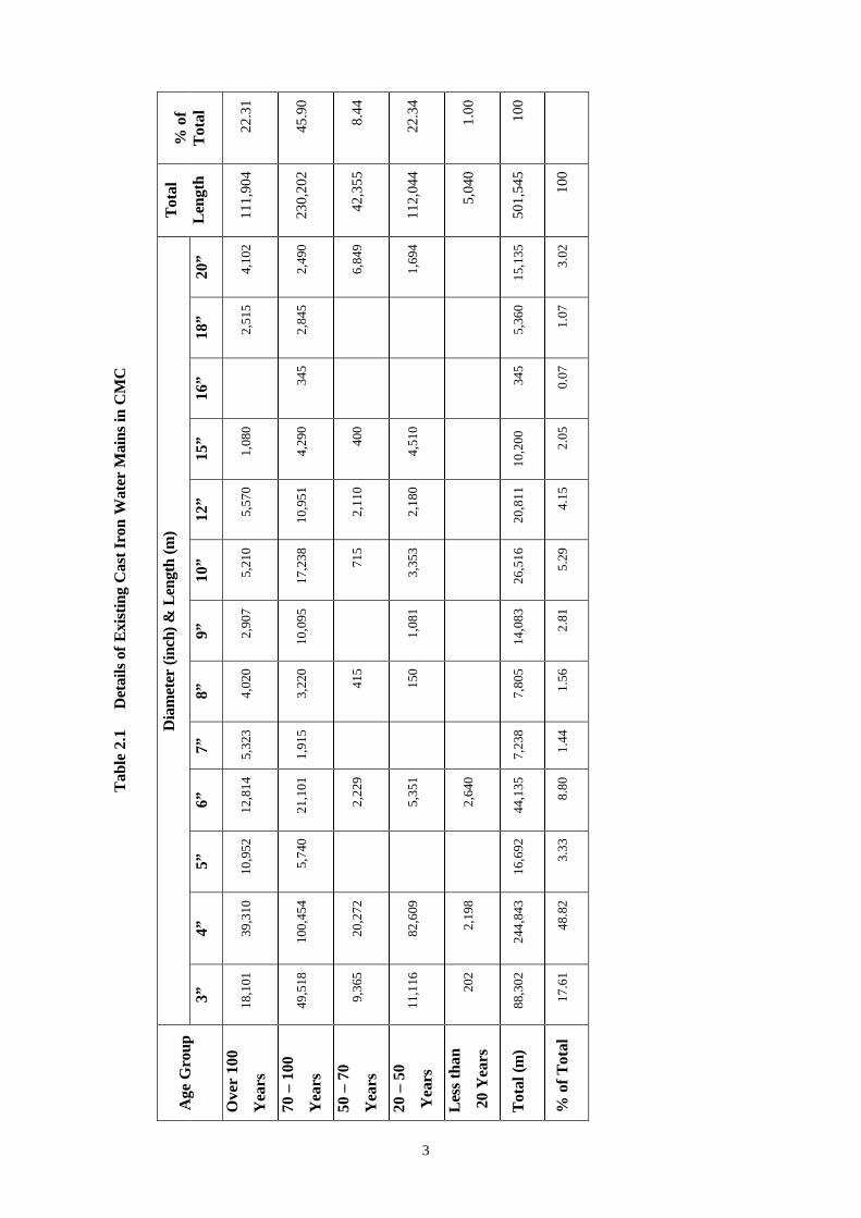
Table 2.1 Details of Existing Cast Iron Water Mains in CMC ............................................. 3
Table 2.2 Main Leaks Attended by CMC in 1999 ............................................................... 2
Table 2.3 Quantification of Main Leaks............................................................................ 11
Table 3.1 Repair of Service Pipe Leaks in CMC in 1999................................................... 20
Table 3.2 Service Pipe Leaks Attended by CMC in 1999.................................................. 22
Table 3.3 Quantification of Service Pipe Leaks................................................................. 24

ABBREVIATIONS
ABBREVIATIONS AND TERMINOLOGY
AC - Asbestos Cement
AGF - Above Ground Floor
AGM - Additional General Manager
AS - Australian Standards
AWWA - American Water Works Association
B/C - Benefit Cost Ratio
BOQ - Bill of Quantity
BS - British Standards
BWL - Bottom Water Level
CDC - Community Development Council
CEB - Ceylon Electricity Board
CI - Cast Iron
CMC - Colombo Municipal Council
CSPU - Clean Settlement Program Unit of the Ministry of Urban Development, Construction and
Public Utilities
DG - Diesel Engine Generator
DGM - Deputy General Manager
DI - Ductile Iron
dia. - Diameter
E/N - Exchange Notes
GC - Greater Colombo
GI - Galvanized Mild Steel Pipe
GM - General Manager
GOJ - Government of Japan
GOSL - Government of Sri Lanka
GR - Ground Reservoir
GST - Goods and Services Tax
GWL - Ground Water Level
HP - Horsepower
HWL - High Water Level
I/O - Input-output
ICB - International Competitive Bidding
ICTAD - Institute for Construction Training and Development

IDA - International Development Agency
IEE - Institution of Electrical Engineers
IRR - Internal Rate of Return
ISO - International Organization for Standardization
JBIC - Japan Bank for International Cooperation
JICA - Japan International Cooperation Agency
JST - JICA Study Team
LCB - Local Competitive Bidding
LDB - Lighting Distribution Board
LECO - Lanka Electricity Corporation
LI - Langelier's Saturation Index
LV - Low Voltage
LWL - Low Water Level
M/D - Minutes of Discussion
MCCB - Molded Case Circuit Breaker
MDPE - Medium Density Polyethylene
MLD - Million Litre per Day
MS - Mild Steel
MSB - Main Switch Board
MSL - Mean Sea Level
MUDCP - Ministry of Urban Development, Construction and Public Utilities
NCCSL - National Construction Contractor Association
ND, DN - Nominal Diameter
NGO - Non-government Organization
NHDA - National Housing Development Authority
NPV - Nett Present Value
NRW - Non-revenue Water
NWSDB - Notional Water Supply and Drainage Board
O&M - Operation & Maintenance
ODA - Official Development Assistance
OPC - Ordinary Portland Cement
PDB - Power Distribution Board
PIU - Project Implementation Unit
PLC - Programmable Logic Controller
PQ - Prequalification
PRDA - Provincial Road Development Authority
PS - Polis Station
PVC, uPVC - (Unplasticized) Polyvinyl Chloride

R/C, RC - Reinforced Concrete
RDA - Road Development Authority
RSC - Regional Support Centre of the National Water Supply and Drainage Board
S/W - Scope of Work
SAPROF - Special Assistance for Project Formation
SAPS - Special Assistance for Project Sustainability
SDB - Socket Distribution Board
SLLRDC - Sri Lankan Land Reclamation and Development Corporation
SLS - Serviceability Limit State
SLT - Sri Lanka Telecom
SPSS - Statistical Package for Social Sciences
STP - Sustainable Township Programme of the Ministry of Urban Development, Construction and
Public Utilities
TDH - Total Dynamic Head
TG - Tenement Garden
TM - Transmission Main
TOR - Terms of Reference
TP&N, TPN - Three Pole and Neutral
TWL - Top Water Level
UDA - Urban Development Authority
UFW - Unaccounted-for Water
ULS - Ultimate Limit State
UPDB - Utilities Power Distribution Board
VH - Valve House
WTP - Water Treatment Plant
XLPE - Cross-linked Polyethylene Insulated Vinyl Sheath
UNITS
A, amp, Amp - Ampere oC - Celsius
cm - Centimetre
d - Day
dB - Decibel
h, hr, Hr - Hour
ha - Hectare
Hz - Hertz

kg - Kilogram
km - kilometre
kN - kilonewton
kVA - Kilovolt-ampere
kW - Kilowatt
L, l, ltr - Litre
lpcd, lcd - Liter per Capita per Day
m, M - Metre, Million
m2, sqm - Square Metre
m3, cum - Cubic Metre
mg - Milligram
MG - Million Imperial Gallon
min - Minutes
mm - Millimetre
mm2, sqmm - Square Millimetre
mph - Mile per Hour
N - Newton
pH - Potential of Hydrogen
ppm - Parts per Million
psi - Pounds per Square Inch
Rs. - Sri Lankan Rupee
s, sec - Second
V - Volt
W - Watt

1
1. INTRODUCTION
It is widely accepted that the Non-Revenue water (NRW) in Colombo City is around 50% of
the total supply, and that leakage in the distribution system constitutes a great part of NRW.
The decrease in the volume of NRW by abatement of leakage and reduction of wastage is
therefore indispensable for making adequate water available for the new service areas expanded
by the Towns East, Towns South and Towns North projects, while, in the meantime, the new
Kalu Ganga scheme is developed. If NRW remains at the present high levels, not only the
recently completed Towns East and Towns South projects but also the proposed Towns North
Project will face severe water shortages in the near future.
Furthermore, the present high NRW level is one of the major reasons for the weak financial
conditions of NWSDB. In this context, the Japanese Government has agreed to finance this
Project for Reduction of Non-Revenue Water.
As part of this Project, approximately 2,340 leaks in the distribution pipes with diameters 2 to 8
inches and 9,000 leaks in service pipes will be repaired within CMC area.
2. LEAK REPAIR WORK OF DISTRIBUTION PIPES (2” – 8”)
2.1 GENERAL
National Water Supply and Drainage Board (NWSDB) supplies water to approximately 73,500
service connections in CMC area, encompassing nearly 36 square kilometers. According to the
recent statistics, the CMC distribution system consists of approximately 500km of cast iron
water mains ranging from 4” to 30” and very limited lengths of DI, PVC, AC and GI pipes.
Many main leaks have occurred due to aging cast iron pipes installed in the late 1800’s and
early 1900’s. As can be seen in Table 2.1, 22% of cast iron pipes in CMC area are over 100
years old and nearly 80% are over 50 years old. Almost all cast iron pipes have been installed
without a protective internal lining, which is the primary cause of many internal corrosion leaks.
Insufficient covers to the pipe and the increasing traffic loadings have caused many structural
failures in the pipeline. The compositions of existing cast iron pipes in terms of their age are
given in Table 2.1.

2
2.2 DATA AVAILABLE
The majority of main leaks are currently repaired by Water Works Department of CMC under a
contract with NWSDB, whilst very few main leak repairs are conducted by NRW Reduction
Unit or the Area Engineers of NWSDB. The summary of the main leak repairs attended by
CMC is given in Table 2.2.
Table 2.2 Main Leaks Attended by CMC in 1999
Leaks Attended by CMC Month
Pipe Leaks Joint Leaks Hydrant Leaks Valve Leaks Total
Jan-99 57 23 3 8 91
Feb-99 67 20 12 32 131
Mar-99 71 28 2 10 111
Apr-99 68 23 0 20 111
May-99 50 34 15 20 119
Jun-99 92 48 10 20 170
Jul-99 89 51 4 7 151
Aug-99 72 68 1 30 171
Sep-99 61 47 5 20 133
Oct-99 67 26 11 22 126
Nov-99 158 81 8 20 267
Dec-99 68 41 9 18 136
Total 920 490 80 227 1,717
Unfortunately however, these leak records do not contain details, such as the type of leaks,
repair materials used or repair costs involved.
Main leak repairs in CMC area average 143 leaks per month with the total being approximately
1,700 leaks per year.
Tab
le 2
.1
Det
ails
of
Exi
stin
g C
ast I
ron
Wat
er M
ains
in C
MC
Dia
met
er (
inch
) &
Len
gth
(m)
Age
Gro
up
3”
4”
5”
6”
7”
8”
9”
10”
12”
15”
16”
18”
20”
Tot
al
Len
gth
% o
f T
otal
Ove
r 10
0
Yea
rs
18,1
01
39,3
10
10,9
52
12,8
14
5,32
3 4,
020
2,90
7 5,
210
5,57
0 1,
080
2,
515
4,10
2 11
1,90
4 22
.31
70 –
100
Yea
rs
49,5
18
100,
454
5,74
0 21
,101
1,
915
3,22
0 10
,095
17
,238
10
,951
4,
290
345
2,84
5 2,
490
230,
202
45.9
0
50 –
70
Yea
rs
9,36
5 20
,272
2,22
9
415
71
5 2,
110
400
6,84
9 42
,355
8.
44
20 –
50
Yea
rs
11,1
16
82,6
09
5,
351
15
0 1,
081
3,35
3 2,
180
4,51
0
1,
694
112,
044
22.3
4
Les
s th
an
20
Yea
rs
202
2,19
8
2,64
0
5,04
0 1.
00
Tot
al (m
) 88
,302
24
4,84
3 16
,692
44
,135
7,
238
7,80
5 14
,083
26
,516
20
,811
10
,200
34
5 5,
360
15,1
35
501,
545
100
% o
f T
otal
17
.61
48.8
2 3.
33
8.80
1.
44
1.56
2.
81
5.29
4.
15
2.05
0.
07
1.07
3.
02
100
3

4
2.3 TYPE OF LEAKS
Having examined the main leak repair records and discussed with CMC staffs in charge of leak
repair, the following major types of leaks were identified.
(a). Joint leaks (lead joints in CI pipes)
(b). Leakage through pinholes and corrosion holes in the pipe
(c). Leakage through circumferential cracks in the pipe
(d). Leakage through longitudinal cracks in the pipe
(e). Fire hydrant leaks
(f). Gate valve leaks (Gland Leaks)
(g). Air valve leaks
(h). Leakage due to manmade damages as a result of
• Extensive damage to the pipe barrel
• Holes created by sharp objects such as tooth of a back hoe
• Pulled-out service connections causing damage to the pipe at the tapping
• Scraping/lining work conducted in the past
2.4 TYPE OF AVAILABLE REPAIR MATERIALS
The industry offers a variety of materials for quick and reliable repair of the above leaks. They
are:
(a). Saddle straps
(b). Full circle repair clamps (Split Collar and Wrap-Around Types)
(c). Full circle repair saddles (Split Collar and Wrap-Around Types with Threaded Outlets
for service connections)
(d). Bell joint leak clamps
(e). Slip couplings
(f). PVC repair sockets (for PVC pipes only)
Saddle Straps
Gunmetal saddle strap provides a quick and cost effective method to repair a point leak,
which can be accommodated within the small circular gasket of the saddle strap.
Full Circle Repair Clamps
These types of clamps are similar to Viking Johnson EasiClamp made of Malleable
Iron or Ductile Iron and Viking Johnson HandiClamp made of stainless steel or similar
products.

5
This repair clamp is suitable for Cast Iron, Ductile Iron or PVC pipes for any given
nominal diameters. These clamps guarantee a reliable, permanent seal even on badly
corroded pipes. A circumferential waffle gasket provides a leaklight seal, which caters
for pinholes and corrosion holes, impact damages, circumferential and longitudinal
cracks. The length of the clamp for nominal pipe diameters of 3” – 8” is 200mm. The
half housings are made of malleable iron or ductile iron.
VJ handiClamp or similar products are constructed of stainless steel and suitable for
use on Cast Iron, Ductile Iron or PVC on nominal bore. These clamps are designed to
seal pinholes and corrosion holes, impact damages and longitudinal cracks but do not
provide seal for circumferential cracks. However, they are available in different clamp
lengths exceeding 200mm as in the case of VJ EasyClamp and similar products.
If the extent of the pipe damage is greater than the available length of these clamps, it
is recommended that a cutout repair be undertaken.
Full Circle Repair Saddles
These types of saddles are similar to Viking Johnson EasiTap made of Malleable Iron
or Ductile Iron and Viking Johnson HandiTap made of stainless steel. These repair
saddles are used when the leakage is associated with a service connection.
This type of saddles provides a quick and cost effective method to repair the leak and
reinstall or replace the affected service pipe connection whilst under pressure. This type
of clamps incorporates either a female threaded outlet or a drilled and tapped boss to
allow a simple under pressure connections to be made using standard tapping machine.
Bell Joint Leak Clamps
This type of clamps is similar to VJ EasiCollar clamps and is suitable to repair joint
leaks in Cast Iron, Ductile Iron and PVC pipes. This is an adaptable repair collar that
provides an effective, permanent repair to leaking spigot and socket joint. Once
installed the gasket reinforces the seal of the socket and spigot joint.
Slip Couplings
This type of couplings is similar to VJ MaxiFit Couplings and caters for all popular
sizes and types of Cast Iron, Ductile Iron and PVC pipes. The damage length of pipe is
cut off and replaced with a new piece of pipe with Slip Couplings on either side.
PVC Repair Sockets

6
This type of repair sockets provide a cost effective method of replacing a damaged
length of PVC pipes with a new piece of PVC pipe with PVC repair sockets on either
side.
2.5 CLASSIFICATION OF LEAKS
The type of leaks varies from one place to another and difficult to classify in a simple manner.
However, as the cost of leak repair depends largely on the materials used, it is relatively easy to
classify the leaks according to the type of repair methods to be adopted in the project
implementation stage.
The following leakage types are thus identified for given pipe sizes so that each type of leak
can be evaluated for the corresponding pipe sizes.
Type A Small point leaks that can be repaired with a typical Brass Saddle Strap,
similar to Talbot Flat Boss Strap.
Type B Corrosion holes, longitudinal cracks, impact damages and
circumferential breaks with the affected width of the pipe not greater
than 200mm (for the diameter range of 3” – 8”) that can be repaired
with a Malleable Iron/Ductile Iron Full Circle Repair Clamp similar to
VJ EasiClamp. (Split Collars)
Type B1 Leak Type as in Type B above but associated with a service connection
that can be repaired with a Malleable Iron / Ductile Iron, Full Circle
Repair Saddle similar to VJ EasiTap. (Split Collar with threaded outlet
for service pipe)
Type C Corrosion holes, longitudinal cracks and impact damages with the
affected width of the pipe between 300 – 400mm (diameter 3” – 8”) that
can be repaired with a stainless steel Full Circle Repair Clamp similar to
VJ HandiClamp. (Wrap-Around Collar)
Type C1 Leak Type as in Type C above but associated with a service connection
that can be repaired with a stainless steel Full Circle Repair Saddle
similar to VJ HandiTap. (Wrap-Around Collar with threaded outlet for
service pipe)
Type D Point damage or localized damage in PVC pipes that can be repaired
with a PVC Bell Soketted Repair Socket.

7
Type E Extensive damage, which require the replacement of the affected length
of the CI pipe with two Slip Couplings similar to VJ MaxiFit on both
sides.
Type E1 Extensive damage, which requires the replacement of the affected length
of the PVC pipe with two PVC Bell Ended Sleeve Joints on both sides.
Type F Joint leaks in Cast Iron pipes, which can be repaired by Re-caulking
with or without additional lead with a variety of small to large
pneumatic or hand caulking irons, forcing the lead back into the bells.
Type F1 Joint leaks in Cast Iron or PVC pipes, which require Bell Joint Leak
Clamp similar to VJ EasiCollar.
Type G1 Fire Hydrants leaks (Wedge Gate Type), which require the replacement
of damaged Gaskets / O’Rings or similar replaceable items.
Type G2 Fire Hydrants leaks (Wedge Gate Type), which require the replacement
of the leaking Hydrant.
Type G3 Fire Hydrant leaks (Duck Foot Bend Type), which require the
replacement of damaged Gaskets / O’Rings or similar replaceable items.
Type G4 Fire Hydrant leaks (Duck Foot Bend Type), which require the
replacement of the leaking Hydrant.
Type H Air Valve leaks which requires the replacement of damaged Gaskets /
O”Rings or similar replaceable items.
Type H1 Air Valve leaks which requires the replacement of the leaking Air Valve.
Type J Gate Valve leaks which can be repaired by replacing the damaged
Gaskets / O’Rings or similar replacement items
Type J1 Gate Valve leaks which needs replacement of the leaking valve with
new Double Flange Valve.
2.6 QUANTIFICATION OF LEAK TYPES
The Contract for main leak repair works will be awarded to local contractors on a unit price
basis. However, it is necessary to quantify the leak types in order to prepare the Bill of
Quantities for procurement of necessary repair materials as well as for evaluation of bids.
Materials will be purchased under the project and handed over to the Contractor. NWSDB will
furnish necessary repair materials to the contractor on a day-to-day basis.

8
The scope of work indicates that approximately 2,340 leaks in distribution pipes (2 to 8 inches)
in the CMC area be repaired. As shown in Table 2.2, the following main leaks were attended by
CMC in the year 1999.
Pipe Leaks 920 Nos 54%
Joint Leaks 490 Nos. 28%
Hydrant Leaks 80 Nos. 5%
Valve Leaks 227 Nos. 13%
Total 1,717 Nos. 100%
Applying the same percentages, 2,340 leaks are broken down into components as shown below.
Main Leaks 1,260 Nos.
Joint Leaks 660 Nos.
Hydrant Leaks 120 Nos.
Valve Leaks 300 Nos.
Total 2,340 Nos.
The CMC leak repair records do not indicate the pipe diameters on which repairs have been
made. However, limited records available at CMC and discussions with CMC and NWSDB
suggested that:
• These leaks occurred mainly on 4” pipes and to a lesser extent on 3” pipes
• Leaks on 5”, 6”, 7” and 8” were very few
• Leaks on pipe sizes exceeding 10” are seldom reported
This corresponds well with the diameter-wise proportions of CI water mains in CMC area as
shown in Table 2.1.

9
When considering diameters only up to 8”, details of cast iron pipes are as follows:
Diameter Length % Estimated
Pipe Leaks
Estimated
Joint Leaks
3”
4”
5”
6”
7”
8”
88,302
244,843
16,692
44,135
7,238
7,805
21.59
59.86
4.08
10.79
1.77
1.91
273
757
52
136
22
24
141
392
27
71
12
12
Total 409,015 100% 1,264 655
According to the SAPS report, existing fire hydrants in CMC area are of two types. They are:
- Wedge Gate Type Fire Hydrants
- Duckfoot Bend Type Hydrants
The details given in the report are as follows:
Type of Fire Hydrant Nos. Percentage
Wedge Gate Type
Duck Foot Bend Type
1,767
593
75%
25%
Total 2,360 100%
Total number of valve leaks is estimated at 300. Assuming that 10% of valve leaks are
pertaining to fire hydrants, it is estimated that the number of fire hydrant leaks to be attended
by the project will be 30. Therefore the total number of gate valve leaks will remain at 270.
According to the SAPS report, the number of 3” – 8” gate valves is as follows:
Diameter No. of Valves %
3”
4”
5”
593
1,376
92
25
60
4

10
6”
7”
8”
167
38
44
7
2
2
Total 2,301 100%
Applying the same percentages, the number of leaks expected to be made for each valve size
is estimated as follows:
Valve Diameter % No. of Valve Leaks
to be Attended
3”
4”
5”
6”
7”
8”
25
60
4
7
2
2
68
162
10
20
5
5
TOTAL 100 270
Cast Iron pipe leaks comprise leak types A, B, B1, C, C1 and E.
Type D and E1 are exclusively for PVC pipes and a reasonable allowance shall be made for
repairing PVC pipes within the CMC area, as these pipes are more vulnerable to damages due
to excavation work being carried out by various utility agencies.
Cast Iron Joint leaks comprise leak types F and F1 and some allowance shall be made in leak
Type F1 for possible joint leaks in pipe materials other than CI.
Leak types G1, G2, G3 and G4 are for fire hydrant leaks of wedge gate type and duck-foot
bend type.
Leak types H1 and H2 are for air valve leaks while leak types J and J1 are for gate valve leaks.
These leak types are illustrated in the Standard Drawings.

11
The estimated quantification of leak types is indicated in Table 2.3.
Table 2.3 Quantification of Main Leaks
Pipe Diameter Leak Type
Assumed
% Category
3” 4” 5” 6” 7” 8” Total
Type A 20% 54 152 10 28 4 4 252
Type B 20% 54 152 10 28 4 4 252
Type B1 10% 27 76 5 14 2 2 126
Type C 10% 27 76 5 14 2 2 126
Type C1 10% 27 76 5 14 2 2 126
Type D 10% 27 76 19 4 126
Type E 10% 27 76 5 14 2 2 126
Type E1 10%
Main
Leaks
27 76 19 4 126
Sub-Total 100% 270 760 40 150 16 24 1,260
Type F 90% 125 350 27 63 9 18 992
Type F1 10%
Joint
Leaks 15 40 3 7 1 2 68
Sub-Total 100% 140 390 30 70 10 20 660
Type G1 67.5% 81
Type G2 7.5% Wedge Gate Type (75%)
9
Type G3 22.5% 27
Type G4 2.5%
Fire
Hydrant
Leaks Duck-Foot Type (25%) 3
Sub-Total 100% 120
Type H 66% 20
Type H1 34%
Air Valve
Leaks 80mm Double Orifice Air Valve
10
Sub-Total 100% 30
Type J 90% 61 146 9 18 4 4 242
Type J1 10%
Gate Valve
Leaks 7 16 1 2 1 1 28
Sub-Total 100% 68 162 10 20 5 5 270
Total 2,340

12
2.7 BILL OF QUANTITIES
Item Description Unit Rate Rs.
Qty Amount Rs.
1.0
1.1
1.2
1.3
2.0
2.1
2.2
Repair of Main Leaks. Contractor shall take note on the following matters: (a). All pipe materials, fittings, jointing
materials, specials etc., shall be provided by NWSDB.
(b). Removal of surface, excavation and backfilling shall be paid separately based on unit rates.
(c). The reinstatement cost for asphalt/ premix/tar surfaces, walkways, kerb stones, fences and the like, which will be paid directly to the respective authorities by NWSDB.
(d). All necessary excavation permits including security clearance shall be obtained by the Contractors prior to start any work, NWSDB shall issue letters to the different authorities, but it shall be the responsibility of the Contractor to acquire such permits.
(e). Whenever ordered by the Engineer, the Contractor shall import sand or soil for backfilling. Such imported materials shall be paid separately based on the unit rates.
(f). Contractor shall study all specifications and standard drawings thoroughly in order to get fully acquainted with the work.
Cuttings and removal of asphalt/premix/tar layer from the road surface. The thickness of the layer Not exceeding 150mm Exceeding 150mm but not exceeding 300mm Exceeding 300mm Excavation of earth material including rubble/stone pavement. Rate to include for dewatering and shoring as required. Depth not exceeding 1m. Depth exceeding 1m.
m3
m3
m3
m3
m3
1,050
600
300
6,740
1,680

13
Item Description Unit Rate Rs.
Qty Amount Rs.
3.0
3.1
3.2
3.3
3.4
3.5
3.6
4.0
4.1
4.2
4.3
4.4
4.5
4.6
5.0
5.1
5.2
5.3
5.4
Carryout Type A repair as specified. Rate to include for cleaning the pipe surface, fastening of the clamp saddle according to manufacturers specification and testing repair work by re-pressurizing the main. 3” main 4” main 5” main 6” main 7” main 8” main Carryout Type B repairs as specified. Rate to include for cleaning the pipe surface fastening of the repair saddle according to manufacturers specifications and testing the repair work by re-pressurizing the main. 3” main 4” main 5” main 6” main 7” main 8” main Carryout Type B1 repairs as specified. Rate to include for cleaning the pipe surface, fastening of the repair saddle according to manufacturers specifications, re-tapping the main using standard tapping equipment, restoration of the service connection and testing the repair work by re-pressurizing the main 3” main 4” main 5” main 6” main
No.
No.
No.
No.
No.
No.
No.
No.
No.
No.
No.
No.
No.
No.
No.
No.
54
152
10
28
4
4
54
152
10
28
4
4
27
76
5
14

14
Item Description Unit Rate Rs.
Qty Amount Rs.
5.5
5.6
6.0
6.1
6.2
6.3
6.4
6.5
6.6
7.0
7.1
7.2
7.3
7.4
7.5
7.6
8.0
8.1
7” main 8” main Carryout Type C repairs as specified. Rate to include for cleaning the pipe surface, fastening of the repair saddle according to manufacturers specifications and testing the repair work by re-pressurizing the main. 3” main 4” main 5” main 6” main 7” main 8” main Carryout Type C1 repairs as specified. Rate to include for cleaning the pipe surface, fastening of the repair saddle according to manufacturers specifications, re-tapping the main using standard tapping equipment, restoration of the service connection and testing the repair work by re-pressurizing the main 3” main 4” main 5” main 6” main 7” main 8” main Carryout Type D repairs as specified. Rate to include for exposing the leaking PVC pipe, cutting and removal of the affected length of the pipe, insertion of the PVC bell socket repair socket and testing the repair work by re-pressurizing the main. 3” (80mm) main
No.
No.
No.
No.
No.
No.
No.
No.
No.
No.
No.
No.
No.
No.
No.
2
2
27
76
5
14
2
2
27
76
5
14
2
2
27

15
Item Description Unit Rate Rs.
Qty Amount Rs.
8.2
8.3
8.4
9.0
9.1
9.2
9.3
9.4
9.5
9.6
10.0
10.1
10.2
10.3
10.4
11.0
11.1
11.2
4” (110mm) main 6” (160mm) main 8” (225mm) main Carryout Type E repairs as specified. Rate to include for exposing the leaking pipe, cutting and removal of the affected length of the pipe, preparation of the new pipe piece to suit the gap, fastening of two slip couplings on both sides and testing the repair work by re-pressurizing the main. 3” main 4” main 5” main 6” main 7” main 8” main Carryout Type E1 repairs on PVC mains as specified. Rate to include for exposing the leaking pipe, cutting and removal of the affected length of the pipe, preparation of new pipe piece to suit the gap, fixing of PVC Bell Ended Sleeve Joints on both sides and testing the repair work by re-pressurizing the main. 3” (80mm) main 4” (110mm) main 6” (160mm) main 8” (225mm) main Carryout Type F repairs as specified. Rate to include for re-aligning the joint if necessary, re-caulking with or without additional lead with hand or pneumatic hand caulking tools to achieve a leak tight joint and testing the repair work by re-pressurizing the main. 3” main 4” main
No.
No.
No.
No.
No.
No.
No.
No.
No.
No.
No.
No.
No.
No.
No.
76
19
4
27
76
5
14
2
2
27
76
19
4
125
350

16
Item Description Unit Rate Rs.
Qty Amount Rs.
11.3
11.4
11.5
11.6
12.0
12.1
12.2
12.3
12.4
12.5
12.6
13.0
14.0
15.0
5” main 6” main 7” main 8” main Carryout Type F1 repairs as specified. Rate to include for re-aligning the joint if necessary, removing the lead protruding from the face of the bell in CI pipes, fastening of the Bell Joint leak clamp according to manufacturers specifications and testing the repair work by re-pressurizing the main. 3” CI or 80mm PVC main 4” CI or 110mm PVC main 5” CI main 6” CI or 160mm PVC main 7” CI main 8” CI or 225mm PVC main Carryout Type G1 repairs to wedge gate type fire hydrants. Rate to include for cleaning and dewatering the manhole, temporary dismantling of the manhole (if necessary), effecting the repair, repairs to the manhole (if necessary), placing a new manhole cover (if necessary) and testing the repair work by re-pressurizing the main. Carryout Type G2 works to replace the existing wedge gate type fire hydrant. Rate to include for cleaning and dewatering the manhole, temporary dismantling of the manhole (if necessary), remove old and unserviceable fire hydrants, fixing of a new fire hydrant, re-assemble the manhole, placing a new manhole cover (if necessary) and testing the new fire hydrant by re-pressurizing the main. Carryout Type G3 repairs to Duck-Foot bend type fire hydrants. Rate to include for cleaning and dewatering the manhole,
No.
No.
No.
No.
No.
No.
No.
No.
No.
No.
No.
No.
No.
27
63
9
18
15
40
3
7
1
2
81
9
27

17
Item Description Unit Rate Rs.
Qty Amount Rs.
16.0
17.0
18.0
19.0
19.1
19.2
19.3
19.4
19.5
temporary dismantling of the manhole (if necessary), conducting the repair, repairs to the manhole (if necessary), placing a new manhole cover (if necessary) and testing the repair work by re-pressurizing the main. Carryout Type G4 works to replace the existing Duck-Foot bend type fire hydrant. Rate to include for excavating, cleaning and dewatering the manhole, temporary dismantling of the manhole (if necessary), remove old and unserviceable fire hydrant, fixing of a new fire hydrant, re-assemble the manhole, placing a new manhole cover (if necessary) and testing the new fire hydrant by re-pressurizing the main. Carryout Type H repairs to Air valves. Rate to include for cleaning and dewatering the manhole, temporary dismantling of the manhole (if necessary), conducting the repair, repairs to the manhole (if necessary) and testing the repair, work by pressurizing the main. Carryout Type H1 works to replace the existing Air Valve. Rate to include for cleaning and dewatering the manhole, temporary dismantling of the manhole (if necessary), remove old and unserviceable Air Valve, fixing of a new Air Valve, re-assemble the manhole and testing the new Air Valve by re-pressurizing the main. Carryout Type J repair work to existing Gate Valves. Rate to include for excavation, dismantling of protection tube/surface box assembly, dewatering, carrying out the necessary repair as specified, re-assemble of protection tube/surface box assembly (provide new assembly if necessary), testing the repair work by re-pressurizing the main. 3” Gate Valve 4” Gate Valve 5” Gate Valve 6” Gate Valve 7” Gate Valve
No.
No.
No.
No.
No.
No.
No.
No.
3
20
10
61
146
9
18
4

18
Item Description Unit Rate Rs.
Qty Amount Rs.
19.6
20.0
20.1
20.2
20.3
20.4
20.5
20.6
21.0
22.0
23.0
24.0
8” Gate Valve Carryout Type J1 repair work to replace the existing unserviceable gate valve. Rate to include for dewatering, dismantling of the protection tube/surface box assembly removal of the valve, installation of new double flange gate valve with flanged spigot, flanged adapter and slip coupling as specified, re-assemble of protection tube/surface box assembly (provide new assembly if necessary), testing the repair work by re-pressurizing the main. 3” Gate Valve 4” Gate Valve 5” Gate Valve 6” Gate Valve 7” Gate Valve 8” Gate Valve Backfilling of the excavated area as specified. Rate to include for removal of excessively wet soil from site as directed by the Engineer, import of suitable backfill material from outside, carryout compaction in layers as specified, prepare the excavated surface suitable for vehicular traffic and cleaning the working area to the satisfaction by the Engineer. Import of sand as backfill material. Import of suitable soil as backfill material. Temporary road surface reinstatement at road crossings and other places as instructed by Engineer.
No.
No.
No.
No.
No.
No.
No.
m3
m3
m3
m2
4
7
16
1
2
1
1
8,420
840
840
3,000
19
3. LEAK REPAIR WORK OF SERVICE PIPES
3.1 GENERAL
Until 1972, all service connections in CMC were given using Galvanized Mild Steel (GI) pipes.
The use of PVC pipes for service connections was started in 1972. Since then, NWSDB and
CMC have been replacing GI pipes with PVC pipes wherever leaks were detected in GI service
pipes. However, it is believed that a large number of GI service pipes still remain unreplaced in
the CMC area. The exact number of such GI service pipes is unknown. This project intends to
replace GI service pipes, which can be detected or identified during the implementation of the
project.
It has been identified that a significantly large number of leaks exist in service pipes and the
repair of service pipe leaks is an essential part of any leakage abatement program.
3.2 DATA AVAILABLE
The service pipe leaks are currently attended by CMC, as well as by NRW Unit and Area
Offices (CB1, CB2 and CB3) of NWSDB. However, most of the leak repair records are
incomplete and it is difficult to determine the type of leaks, repair materials used, and
respective repair costs involved.
Table 3.1 gives a summary of the leak repairs in service pipes carried out by all parties during
the year 1999. It can be seen in the table that most of the data are not available. It is however
calculated that more than 1,082 service pipe leaks were repaired in 1999.

20
Table 3.1 Repair of Service Pipe Leaks in CMC in 1999
NWSDB Area Office NWSDB NRW Unit Month CMC
CB1 CB2 CB3 CB1 CB2 CB3
January 44 NA NA 7 17 44 16
February 48 NA NA 2 39 27 12
March 48 NA NA 7 31 51 NA
April 23 NA NA 1 1 13 NA
May 51 NA NA 5 27 13 NA
June 74 NA NA 10 NA 37 NA
July 63 NA NA 6 25 NA NA
August 71 NA NA 2 7 NA NA
September 61 NA NA 11 NA NA NA
October 53 NA NA 5 NA NA NA
November 51 12 NA 9 NA NA NA
December 33 14 NA 11 NA NA NA
TOTAL 620 26+ NA 76 147+ 185+ 28+
NA – Records Not Available
3.3 TYPE OF SERVICE PIPE LEAKS
In general, leaks in service pipes can be classified into the following types.
1. Leak from the saddle (No pipe damage) due to failure in the saddle, loosening of the
saddle due to corroded nuts and bolts, displacement or failure of the rubber gaskets.
2. Ferrule leak
3. Leakage of PVC fittings at the ferrule
4. Leakage in the communication pipe
5. Leakage at stopcocks near the meter
6. Leakage at meter unions
As the leak types 1,2,3 above occur at tapping points, they can be grouped into one leak type.
Leaks at stopcocks require a minor repair of the taps or replacement of the same if they have
been worn out beyond repair. Water meter leak requires mainly re-washering work to stop
leaks. Service pipe leaks require the replacement of the damaged length.

21
Apart from the above leaks, it is also necessary to replace existing GI communication pipes, as
they have already developed or will develop leaks shortly.
It should also be noted that some PVC service pipes are laid exposed across the drains and
culverts, being quite vulnerable to damages by vehicles or vandalism. GI pipe casings shall be
provided wherever possible at these locations.
It has been also observed that many long service pipes are laid along the same by-road. These
service pipes are popularly known as the “spaghetti pipes”. A narrow road off Kelaniya Mill
road in Modera has 18 such service connections all laid along the same road. Most of these
connections are exposed to sunlight and flattened by vehicles. They were found to be leaking
severely. Such roads need a common distribution main so that individual houses could get a
connection with a short length of service pipe.
3.4 QUANTIFICATION OF LEAK TYPES
The contract for service pipe leak repair works will be awarded to local contractors on a unit
price contract basis. However, it is necessary to quantify the leak types in order to prepare the
Bill of Quantities for procurement of necessary repair materials as well as for evaluation of bids.
It is intended that approximately 9,000 leaks in service connection pipes in the CMC area will
be repaired under this contract.
For the purpose of preparing Bill of Quantities, it is assumed that the service pipe leaks can be
grouped into the following four main categories.
1. Leaks in PVC service pipes where the service pipes are laid underground at proper
depths (6,000 service connections).
2. Leaks in existing old GI service pipes, which need complete replacements from the
ferrule to the water meter (1,000 service connections).
3. Leaks in existing exposed PVC service pipes at drain crossings, which need repair
and GI pipe encasement to protect the PVC pipe (1,000 service connections).
4. Leaks in existing PVC or GI multiple service pipes (spaghetti pipes), which require
the laying of an additional common main, transferring of existing services to the
common main and plugging off multiple taps on the distribution main (1,000 service
connections).

22
3.4.1 Quantification of Leaks in Service Pipes
The data maintained by both CMC and NWSDB on service pipe repairs are insufficient to form
a reasonable basis for quantification of different leak types identified under Section 3.3.
However, discussion with NWSDB and CMC indicate that the number of leaks at tapping
points, water meters and stopcocks is very small compared to the leaks at communication pipes.
Meter leaks are attended by NWSDB based on the information provided by the meter readers.
No records on meter repairs are maintained, since only re-washering is needed to rectify most
of the meter leaks.
Table 3.2 shows a rough breakdown of service pipe leaks attended by CMC in 1999. The study
team obtained this information by re-organizing available records from CMC, which are
grossly incomplete and unorganized. The information gives some idea about the proportions of
leak types.
Table 3.2 Service Pipe Leaks Attended by CMC in 1999.
Month Saddle/Ferrule Valve Service Pipe Total
January 1 3 40 44
February 2 4 42 48
March 2 5 41 48
April - 2 21 23
May 2 4 45 51
June 3 6 65 74
July 2 4 57 63
August 4 5 62 71
September 2 4 55 61
October 3 5 45 53
November 1 3 47 51
December 1 2 30 33
Total 23 47 550 620
% 4% 8% 88% 100%
However, the study team evaluated that the number of leaks at saddle/ferrule connections are
under-recorded, as they are located deep under the road surface and are difficult to detect.
Apart from this, there is reluctance from all parties to attend these leaks, as the repair work
requires the breakage of tarred surface or road pavement, deep excavation to expose the leaks
and interruption of traffic.

23
As such, the percentages of various leak types are assessed in the following manner in order to
quantify the leak types.
Leak Type % No. of leaks to be
Attended
Saddle/Ferrule Leaks
Service Pipe Leaks
Stopcock Leaks
Water Meter Leaks
10%
70%
10%
10%
600
4,200
600
600
TOTAL 100% 6,000 Nos.
The distribution of service connections in terms of their size is assumed as follows.
Size of Service Connection Ferrules Service Pipes, Stopcocks
and Meters etc.,
½” (20mm)
¾” (25mm)
1” (32mm)
1½” (50mm)
2” (63mm)
3” (90mm)
4” (110mm)
70%
20%
5%
2%
3%
-
-
70%
20%
5%
1%
2%
1%
1%
The corresponding numbers of leak types and the quantity of ferrules and stopcocks to be
procured by NWSDB are given in Table 3.3. It is assumed that 50% of existing ferrules and
stopcocks can be reused after repair. NWSDB shall furnish to the contractor all PVC pipes and
fittings, ferrules, stopcocks and water meters to be required for repairing service pipe leaks.

24
Table 3.3 – Quantification of Service Pipe Leaks
Diameter
Leak Type ½”
(70%)
¾”
(20%)
1”
(5%)
1½”
(1%)
2”
(2%)
3”
(1%)
4”
(1%)
Total
Saddle/Ferrule
Leak 420 120 30 12 18 - - 600
Communication
Pipe Leak
2,940
840
210
42
84
42
42
4,200
Stopcock Leaks 420 120 20 6 12 6 6 600
Water Meter
Leaks
420
120
30
6
12
6
6
600
Total 4,200 1,200 300 60 120 60 60 6,000
Materials to be Procured by NWSDB
(It is assumed that 50% of leaking ferrules and stopcocks need to be replaced.)
Diameter Item
½” ¾” 1” 1½” 2” 3” 4” Total
Ferrule 210 60 15 6 9 - - 300
Stopcock 210 60 15 3 6 3 3 300
Water Meter 420 120 30 6 12 6 6 600
3.4.2 Quantification of Leaks in Existing GI Service Pipes
As discussed in Section 3.4, it is assumed that the number of existing GI service connections to
be replaced will be 1,000. Requirements of MDPE materials to replace GI pipes are given in
the following table.

25
GI Service Pipe
Case-1: Main &
Property on the Same
Side
Case-2: Main &
Property on the
Opposite Side
MDPE Pipe
Diameter Number
Number Average
Length
(m)
Number Average
Length
(m)
Diameter
(mm)
Length
Required
(m)
½” GI
¾” GI
1” GI
700
200
100
500
150
75
4
4
4
200
50
25
8
8
8
20
25
32
3,600
1,000
500
TOTAL 1,000 725 - 275 - - 5,100
3.4.3 Quantification of GI Pipe Encasements
It is assumed that 1,000 Nos. of leaking PVC service pipes will be repaired and encased at
drain crossings.
3.4.4 Quantification of Common Mains
It is suggested to eliminate approximately 1,000 leaking PVC service pipes, which have been
laid along by-roads over a long distance and without a sufficient cover. This problem can be
rectified by laying a new common main along the road and by transferring the services on to
the new main. All of the existing multiple tapping connections on the distribution main should
be plugged and the leaking spaghetti pipes should be abandoned.
It is assumed that there are 10 service pipes on average on each by-road for replacement and the
size of common main as 2”. Therefore, common mains will be laid on 100 by-roads to
eliminate 1,000 service pipes. The assumed quantities are as follows.
Service Pipe
(Dia.)
No. of Drain
Crossings
Size of GI
Encasement
Average
Length (m)
Length of GI
Pipe (m)
½” (20mm PVC)
¾” (25mm PVC)
1” (32mm PVC)
700
200
100
1” GI
1¼” GI
1½” GI
1
1
1
700m
200m
100m
TOTAL 1,000 Nos. - - 1,000m

26
Main Size Tapping Arrangement No. of Tapings
(Nos.)
3”
4”
5”
6”
7”
8”
3” x 2” EasiTap
4” x 2” EasiTap
5” x 2” EasiTap
6” x 2” EasiTap
7” x 2” EasiTap
8” x 2” EasiTap
22
60
4
10
2
2
TOTAL 100 Nos.
It is assumed that the average length of 2” common main as 50m. Therefore, the total pipe
material required will be 5,000m of 2” (63mm) PVC pipes.
3.5 BILL OF QUANTITIES
Item Description Unit Rate
Rs.
Qty Amount
Rs.
Repair of service pipe leaks and replacing of
GI service pipes with PVC pipes.
Contractor shall take note on the following
matters:
(a). All pipe materials, fittings, jointing
materials, specials etc., shall be provided
by NWSDB.
(b). Removal of surface, excavation and
backfilling shall be paid separately based
on unit rates.
(c). The reinstatement cost for asphalt/
premix/tar surfaces, walkways, kerb
stores, fences and the like, which will be
paid directly to the respective authorities
by NWSDB.
(d). All necessary excavation permits

27
Item Description Unit Rate
Rs.
Qty Amount
Rs.
1.0
1.1
1.2
1.3
2.0
3.0
including security clearance shall be
obtained by the Contractors prior to start
any work, NWSDB shall issue letters to
the different authorities, but it shall be
the responsibility of the Contractor to
acquire such permits.
(e). Whenever ordered by the Engineer, the
Contractor shall import sand or soil for
backfilling. Such imported materials
shall be paid separately based on the unit
rates.
(f). Contractor shall study all specifications
and standard drawings thoroughly in
order to get fully acquainted with the
work.
Cutting and removal of asphalt/premix/tar
layer from the road surface as directed by the
Engineer.
The thickness of the layer
Not exceeding 150mm
Exceeding 150mm but not exceeding 300mm
Exceeding 300mm
Excavations of earth material including
rubble/stone pavement up to the required
depth below the pipe invert. Rate to include
for dewatering and shoring as required.
Carryout repair to the clamp saddle ferrules
or valve socket at the water main. Rate to
m3
m3
m3
m3
No.
3,400
2,300
1,100
29,360
600

28
Item Description Unit Rate
Rs.
Qty Amount
Rs.
4.0
4.1
4.2
4.3
4.4
4.5
4.6
4.7
5.0
5.1
5.2
5.3
include for continuos dewatering,
replacement or re-adjustment of the clamp
saddle (if necessary), replacement of the
ferrule and valve socket (if necessary) and
testing the repair work by re-pressurizing the
main.
Identify the leaking part of the PVC service
pipe, remove the affected length and fix a
new piece of service pipe of the same
diameter using PVC Solvent Cement type
repair sockets on both sides. Rate shall be
quoted for the following diameters.
20mm (½”) PVC
25mm (¾”) PVC
32mm (1”) PVC
50mm (1½”) PVC
63mm (2”) PVC
90mm (3”) PVC
110mm (4”) PVC
Repair leaks at the water meter. Rate shall be
quoted for the following meter sizes
½” and ¾” water meters
1” to 2” water meters
3” to 4” water meters
No.
No.
No.
No.
No.
No.
No.
No.
No.
No.
2,940
840
210
42
84
42
42
540
48
12

29
Item Description Unit Rate
Rs.
Qty Amount
Rs.
6.0
6.1
6.2
6.3
7.0
7.1
7.2
7.3
8.0
8.1
8.2
8.3
Repair leaks at the stop-taps. Rate to include
for replacement of the stop-taps (if
necessary). Rate shall be quoted for the
following stop-tap sizes.
½” and ¾” stop-taps
1” to 2” stop-taps
3” to 4” stop-taps
Replacement of existing GI service pipes
with MDPE pipes. Rate to include for cutting
and removal of the GI pipe and fixing a new
MDPE pipe from the distribution main upto
the water meter. Rate shall be quoted for the
following diameters.
When the property and the water main are on
the same side of the road.
Replace ½” GI pipe with 20mm MDPE pipe
Replace ¾” GI pipe with 25mm MDPE pipe
Replace 1” GI pipe with 32mm MDPE pipe
Same as in 7.0 but the property and the water
main are on the opposite side of the road
including road excavation.
Replace ½” GI pipe with 20mm MDPE pipe
Replace ¾” GI pipe with 25mm MDPE pipe
Replace 1” GI pipe with 32mm MDPE pipe
No.
No.
No.
m
m
m
m
m
m
540
48
12
2,000
600
300
1,600
400
200

30
Item Description Unit Rate
Rs.
Qty Amount
Rs.
9.0
9.1
10.0
11.0
12.0
13.0
13.1
13.2
13.3
14.0
Replacement of multiple service pipes on
approach roads with a larger diameter
common main. Rate to include for re-
connection of existing service pipes to the
new common main and the plugging of
multiple tapping points at the distribution
main.
63mm PVC common main
Backfilling of the excavation as specified.
Rate to include for removal of excessively
wet soil from site as directed by the
Engineer, import of sand or suitable backfill
material from outside (to be paid separately),
carryout compaction in layers as specified,
prepare the excavated surface suitable for
vehicular traffic and cleaning the working
area of all debris and cleaning the site as
directed by the Engineer.
Import of sand as backfill material
Import of suitable soil as backfill material
Provision of GI pipe casings to exposed PVC
pipes at drains, culverts and other vulnerable
points.
1” GI pipe for ½” PVC pipe
1¼” GI pipe for ¾” PVC pipe
1½” GI pipe for 1” PVC pipe
Temporary road surface reinstatement at road
m
m3
m3
m3
m
m
m
m2
5,000
29,360
3,000
3,000
700
200
100
5,760

31
Item Description Unit Rate
Rs.
Qty Amount
Rs.
crossings and other places as instructed by
Engineer.
4. IMPLEMENTATION OF CONTACT
The contractor for leak repair work of distribution pipes (2” – 8”) and service pipes will be
selected through local competitive bidding (LCB). Local contractors eligible for bidding will
be determined in advance through the process of prequalification conforming to the standard
procedures adopted in Sri Lanka.
The materials required for leak repair will be purchased by NWSDB through already
established procurement procedures and the costs will be reimbursed by JBIC through the JBIC
loan (Loan Agreement No. SL-P66).
The contract will be based on unit rates. Payments to the contractor shall be made for actual
volume of work performed by him based on the unit prices quoted in the Bill of Quantities.
Tenderers shall be requested to indicate in a separate schedule for nighttime unit prices. (10p.m.
to 5a.m.)
The duration of the contract will be approximately 24 months and it will run concurrently with
the rest of the project components.
Fig.4.1 shows a recommended plan for implementation of the contract.

NW
SDB
det
ects
leak
sor
rec
eive
rep
orts
fro
mcu
stom
ers
NW
SDB
rep
airs
leak
s
NW
SDB
, SV
C &
Con
trac
tor
insp
ect
the
site
to c
onfi
rmth
e le
ak
NW
SDB
pay
s to
the
Con
trac
tor
and
supp
lem
ent r
epai
rm
ater
ials
use
d by
Con
trac
tor
NW
SDB
pro
vide
s C
ontr
acto
r a
fix
edqu
antit
y of
rep
air
mat
eria
ls (
suff
icie
ntfo
r ap
prox
. 2-
mon
th w
ork)
NW
SDB
em
ploy
sC
onta
ctor
NW
SDB
, SV
C &
Con
trac
tor
insp
ect
the
leak
and
dec
ide
repa
ir m
etho
ds
NW
SDB
req
uest
sJB
IC f
orre
imbu
rsem
ent o
fm
ater
ial &
labo
urco
sts
JBIC
rei
mbu
rses
the
cost
to N
WSD
Bfr
om J
BIC
loan
App
rox.
2,34
0 le
aks
in D
M&
9,0
00 le
aks
in S
M
The
res
t of
Lea
ks
JST
pre
pare
s T
Ds
(Uni
t P
rice
Con
trac
t)
RE
CO
MM
EN
DE
D I
MP
LE
ME
NT
AT
ION
PR
OG
RA
MM
E F
OR
TH
E C
ON
TR
AC
TF
OR
LE
AK
RE
PA
IR W
OR
KS
Leg
end
SVC
: Con
stru
ctio
n Su
perv
isio
n C
onsu
ltant
; JST
: JIC
A S
tudy
Tea
m;
DM
:Dis
trib
utio
n M
ain;
SM
: Ser
vice
Mai
n; T
D: T
ende
r D
ocum
ents
NW
SDB
info
rms
the
leak
to S
VC
NW
SDB
em
ploy
sSV
C
NW
SDB
issu
esle
tters
to C
ontr
acto
rfo
r ex
cava
tion
perm
its
Con
trac
tor
obta
ins
exca
vatio
n pe
rmits
Con
trac
tor
exca
vate
s th
e si
te
Con
trac
tor
sub
mits
As-
built
dra
win
gsw
ith a
mon
thly
invo
ice
Con
trac
tor
rep
airs
the
leak
und
ersu
perv
ison
of
NW
SDB
and
SV
C
SVC
app
rove
s A
s-bu
ilt d
raw
ings
and
cert
ifie
s th
e m
onth
lyin
voic
e
JBIC
LO
AN
STR
EA
M
MA
IN S
TR
EA
M
FIG
UR
E 4
.1
32

33
5. DIFFICULTIES ENVISAGED AND REMEDIAL MEASURES
(a) It is difficult to assess the nature of the repair works and the costs involved at the design
stage, as the actual leak conditions vary from one place to another. Therefore, it is
suggested that the contract shall be implemented on a basis of unit rates. The
quantification of work, which is based on certain assumptions, will be used only for the
purpose of tender evaluation.
It is recommended that NWSDB commence the repair work as soon as practicable by
using repair materials already available at NWSDB at first and later get them replenished
through the project funds.
(b) As most of the pipeline sections cannot be isolated due to the complex nature of the
junctions, non-availability of valves, non-functioning of valves and non-accessibility to
valves due to over surfacing and other reasons, the contractor may have to carry out most
of leakage repair works under running water. This is a highly undesirable situation, as
this will hinder the progress of the contractor and cause adverse effects on the quality of
the repair. This also runs the risk of contamination of the water in the pipe network.
Therefore, it should be the responsibility of NWSDB to try their best and isolate the
affected section to carryout the repair effectively. It should be noted that the repair of
leak types D, E, E1, G2, and G4; H1 & J1 essentially require the complete stoppage of
water.
(c) Most of the working areas in CMC are congested with utilities such as water mains
(other than the main to be repaired), telecommunication cables, electricity cables and
sewers. Therefore, extreme care should be taken to safe guard these utilities while the
repairs are being affected. As precautionary measures, excavating machinaries and tools
are allowed for removing of the hard asphalt layer only. The subsequent excavation shall
be done manually.
(d) Most roads in the CMC area experience heavy traffic flows. Traffic flow has to be
maintained uninterrupted while repairs are being made. This forces the contractor to
carry out some of the work during the nighttime, which results in increased costs.
Contractor must take this fact into account while quoting his tender prices.
(e) The repair work will require the removal of asphalt layer and in some cases the removal
of kerb stores, tiles in the workways, barricades, fences etc. While reinstatement of kerbs,

34
tiles, barricades and fences is the responsibility of CMC, this requires a proper
coordination among all the parties. Any such additional work will increase the prices to
be quoted by the Contractor.
(f) The working area is densely populated and subjected to considerable pedestrian
movements. The work shall ensure a complete safety to the pedestrian.
All such adverse effects will be highlighted in the project specification, so that the
contractors can quote appropriate rates in their bids.

35
6. STANDARD DRAWINGS
No. Drg.No. Title
1 LR/SD/1 Leak Type A
2 LR/SD/2 Leak Type B
3 LR/SD/3 Leak Type B1
4 LR/SD/4 Leak Type C
5 LR/SD/5 Leak Type C1
6 LR/SD/6 Leak Type D
7 LR/SD/7 Leak Type E
8 LR/SD/8 Leak Type E1
9 LR/SD/9 Leak Type F
10 LR/SD/10 Leak Type F1
11 LR/SD/11 Leak Types G1, G2, G3 & G4
12 LR/SD/12 Leak Type J
13 LR/SD/13 Leak Type J1
14 LR/SD/14 Standard Service Connection – 1
15 LR/SD/15 Standard Service Connection – 2
16 LR/SD/16 Classification of Service Pipe Leaks
17 LR/SD/17 Laying of Common Mains in By-roads
18 LR/SD/18 GI Pipe Encasement

Leak Type - A
THE DETAILED DESIGN STUDY ON THE PROJECT FOR REDUCTION OFNON-REVENUE WATER IN THE GREATER COLOMBO AREA IN THE
DEMOCRATIC SOCIALIST REPUBLIC OF SRI LANKA
SCALE
LR/SD/01
Not to ScaleJICA STUDY TEAM
36

Leak Type - B
THE DETAILED DESIGN STUDY ON THE PROJECT FOR REDUCTION OFNON-REVENUE WATER IN THE GREATER COLOMBO AREA IN THE
DEMOCRATIC SOCIALIST REPUBLIC OF SRI LANKA
SCALE
LR/SD/02
Not to ScaleJICA STUDY TEAM
37

Leak Type - B1
THE DETAILED DESIGN STUDY ON THE PROJECT FOR REDUCTION OFNON-REVENUE WATER IN THE GREATER COLOMBO AREA IN THE
DEMOCRATIC SOCIALIST REPUBLIC OF SRI LANKA
SCALE
LR/SD/03
Not to ScaleJICA STUDY TEAM
38

Leak Type - C
THE DETAILED DESIGN STUDY ON THE PROJECT FOR REDUCTION OFNON-REVENUE WATER IN THE GREATER COLOMBO AREA IN THE
DEMOCRATIC SOCIALIST REPUBLIC OF SRI LANKA
SCALE
LR/SD/04
Not to ScaleJICA STUDY TEAM
39

Leak Type - C1
THE DETAILED DESIGN STUDY ON THE PROJECT FOR REDUCTION OFNON-REVENUE WATER IN THE GREATER COLOMBO AREA IN THE
DEMOCRATIC SOCIALIST REPUBLIC OF SRI LANKA
SCALE
LR/SD/05
Not to ScaleJICA STUDY TEAM
40

Leak Type - D
THE DETAILED DESIGN STUDY ON THE PROJECT FOR REDUCTION OFNON-REVENUE WATER IN THE GREATER COLOMBO AREA IN THE
DEMOCRATIC SOCIALIST REPUBLIC OF SRI LANKA
SCALE
LR/SD/06
Not to ScaleJICA STUDY TEAM
41

Leak Type - E
THE DETAILED DESIGN STUDY ON THE PROJECT FOR REDUCTION OFNON-REVENUE WATER IN THE GREATER COLOMBO AREA IN THE
DEMOCRATIC SOCIALIST REPUBLIC OF SRI LANKA
SCALE
LR/SD/07
Not to ScaleJICA STUDY TEAM
42

Leak Type - E1
THE DETAILED DESIGN STUDY ON THE PROJECT FOR REDUCTION OFNON-REVENUE WATER IN THE GREATER COLOMBO AREA IN THE
DEMOCRATIC SOCIALIST REPUBLIC OF SRI LANKA
SCALE
LR/SD/08
Not to ScaleJICA STUDY TEAM
43

Leak Type - F
THE DETAILED DESIGN STUDY ON THE PROJECT FOR REDUCTION OFNON-REVENUE WATER IN THE GREATER COLOMBO AREA IN THE
DEMOCRATIC SOCIALIST REPUBLIC OF SRI LANKA
SCALE
LR/SD/09
Not to ScaleJICA STUDY TEAM
44

Leak Type - F1
THE DETAILED DESIGN STUDY ON THE PROJECT FOR REDUCTION OFNON-REVENUE WATER IN THE GREATER COLOMBO AREA IN THE
DEMOCRATIC SOCIALIST REPUBLIC OF SRI LANKA
SCALE
LR/SD/10
Not to ScaleJICA STUDY TEAM
45

Leak Types - G1, G2, G3, & G4
THE DETAILED DESIGN STUDY ON THE PROJECT FOR REDUCTION OFNON-REVENUE WATER IN THE GREATER COLOMBO AREA IN THE
DEMOCRATIC SOCIALIST REPUBLIC OF SRI LANKA
SCALE
LR/SD/11
Not to ScaleJICA STUDY TEAM
46

Leak Types - J
THE DETAILED DESIGN STUDY ON THE PROJECT FOR REDUCTION OFNON-REVENUE WATER IN THE GREATER COLOMBO AREA IN THE
DEMOCRATIC SOCIALIST REPUBLIC OF SRI LANKA
SCALE
LR/SD/12
Not to ScaleJICA STUDY TEAM
47

Leak Types - J1
THE DETAILED DESIGN STUDY ON THE PROJECT FOR REDUCTION OFNON-REVENUE WATER IN THE GREATER COLOMBO AREA IN THE
DEMOCRATIC SOCIALIST REPUBLIC OF SRI LANKA
SCALE
LR/SD/13
Not to ScaleJICA STUDY TEAM
48

Standard Service Connection - 1
THE DETAILED DESIGN STUDY ON THE PROJECT FOR REDUCTION OFNON-REVENUE WATER IN THE GREATER COLOMBO AREA IN THE
DEMOCRATIC SOCIALIST REPUBLIC OF SRI LANKA
SCALE
LR/SD/14
Not to ScaleJICA STUDY TEAM
49
2/4/15

Standard Service Connection - 2
THE DETAILED DESIGN STUDY ON THE PROJECT FOR REDUCTION OFNON-REVENUE WATER IN THE GREATER COLOMBO AREA IN THE
DEMOCRATIC SOCIALIST REPUBLIC OF SRI LANKA
SCALE
LR/SD/15
Not to ScaleJICA STUDY TEAM
50

Classification of Service Pipe Leaks
THE DETAILED DESIGN STUDY ON THE PROJECT FOR REDUCTION OFNON-REVENUE WATER IN THE GREATER COLOMBO AREA IN THE
DEMOCRATIC SOCIALIST REPUBLIC OF SRI LANKA
SCALE
LR/SD/16
Not to ScaleJICA STUDY TEAM
51

Laying of Common Water Mains of Byroads
THE DETAILED DESIGN STUDY ON THE PROJECT FOR REDUCTION OFNON-REVENUE WATER IN THE GREATER COLOMBO AREA IN THE
DEMOCRATIC SOCIALIST REPUBLIC OF SRI LANKA
SCALE
LR/SD/17
Not to ScaleJICA STUDY TEAM
52

GI Pipe Encasement
THE DETAILED DESIGN STUDY ON THE PROJECT FOR REDUCTION OFNON-REVENUE WATER IN THE GREATER COLOMBO AREA IN THE
DEMOCRATIC SOCIALIST REPUBLIC OF SRI LANKA
SCALE
LR/SD/18
Not to ScaleJICA STUDY TEAM
53

![arXiv:1403.4462v1 [cs.NA] 17 Mar 2014 · lr arb T r +E = R å r=1 lr ar br +E,(1) where D = diag(l1,l2,. . .,lR) is a scaling (normalizing) matrix, the columns of B represent the](https://static.fdocuments.in/doc/165x107/5f0de9ec7e708231d43cb3ca/arxiv14034462v1-csna-17-mar-2014-lr-arb-t-r-e-r-r1-lr-ar-br-e1-where.jpg)


![[ Appendices ] - JICA](https://static.fdocuments.in/doc/165x107/61bd39fc61276e740b109e6e/-appendices-jica.jpg)

