Design, Production and Placement of Self-Consolidating...
30
Design, Production and Placement of Self-Consolidating Concrete
Transcript of Design, Production and Placement of Self-Consolidating...

Design, Production and Placement of Self-ConsolidatingConcrete

RILEM BOOKSERIESVolume 1
For other titles published in this series, go towww.springer.com/series/8781
Kamal Henri Khayat • Dimitri Feys
Editors
Design, Production and Placementof Self-Consolidating Concrete
Proceedings of SCC2010, Montreal, Canada,September 26–29, 2010

Kamal Henri Khayat Dimitri FeysUniversité de Sherbrooke Université de Sherbrooke
Editors
Springer Dordrecht Heidelberg London New York DOI 10.1007/978-90-481-9664-7
© RILEM 2010No part of this work may be reproduced, stored in a retrieval system, or transmitted in any formor by any means, electronic, mechanical, photocopying, microfilming, recording or otherwise,without written permission from the Publisher, with the exception of any material suppliedspecifically for the purpose of being entered and executed on a computer system, for exclusive useby the purchaser of the work.
Printed on acid-free paper
ISBN 978-90-481-9663-0 e-ISBN 978-90-481-9664-7
Cover design: eStudio Calamar S.L.
Springer is part of Springer Science+Business Media (www.springer.com)
Québec, Canada Québec, Canada
Library of Congress Control Number: 2010932809

Table of Contents
Theme 1: Mix Design for SCC Design and Flow of Powder-type SCC with Crushed Aggregates 3 A. Huss and H.W. Reinhardt ‘Structural Design with Flowable Concrete’ – A fib-Recommendation for Tailor-Made Concrete 13 S. Grünewald, L. Ferrara and F. Dehn Effect of Material Constituents and Mix Design on Performance of SCC for Precast, Prestressed Girders 25 G. Lemieux, S.-D. Hwang and K.H. Khayat Robustness by Mix Design – A New Approach for Mixture Proportioning of SCC 37 P. Ramge and L. Lohaus Theme 2: Chemical Admixtures Smart Polycarboxylate Design for SCC in Precast Applications 53 L. Frunz, D. Lootens, R.J. Flatt, F. Wombacher and U. Velten Effects of Superplasticizer and Viscosity-Modifying Agent on Fresh Concrete Performance of SCC at Varied Ambient Temperatures 65 W. Schmidt, J. Brouwers, H.-C. Kühne and B. Meng Selecting Admixtures to Achieve Application-Required Rheology 79 E.Koehler, A. Jeknavorian and S. Klaus
v
Preface ix Conference Committees xi
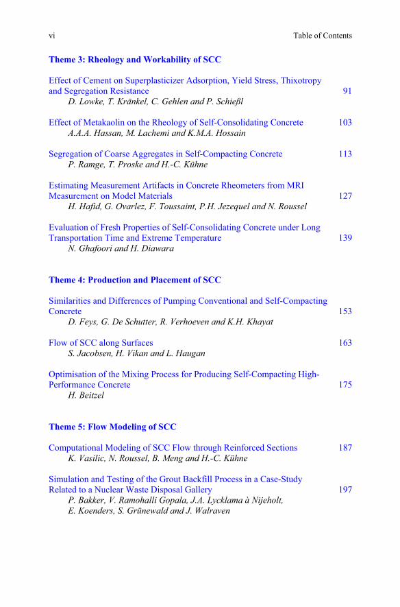
Table of Contents vi
Theme 3: Rheology and Workability of SCC Effect of Cement on Superplasticizer Adsorption, Yield Stress, Thixotropy and Segregation Resistance 91 D. Lowke, T. Kränkel, C. Gehlen and P. Schießl Effect of Metakaolin on the Rheology of Self-Consolidating Concrete 103 A.A.A. Hassan, M. Lachemi and K.M.A. Hossain Segregation of Coarse Aggregates in Self-Compacting Concrete 113 P. Ramge, T. Proske and H.-C. Kühne Estimating Measurement Artifacts in Concrete Rheometers from MRI Measurement on Model Materials 127 H. Hafid, G. Ovarlez, F. Toussaint, P.H. Jezequel and N. Roussel Evaluation of Fresh Properties of Self-Consolidating Concrete under Long Transportation Time and Extreme Temperature 139 N. Ghafoori and H. Diawara Theme 4: Production and Placement of SCC Similarities and Differences of Pumping Conventional and Self-Compacting Concrete 153 D. Feys, G. De Schutter, R. Verhoeven and K.H. Khayat Flow of SCC along Surfaces 163 S. Jacobsen, H. Vikan and L. Haugan Optimisation of the Mixing Process for Producing Self-Compacting High-Performance Concrete 175 H. Beitzel Theme 5: Flow Modeling of SCC Computational Modeling of SCC Flow through Reinforced Sections 187 K. Vasilic, N. Roussel, B. Meng and H.-C. Kühne Simulation and Testing of the Grout Backfill Process in a Case-Study Related to a Nuclear Waste Disposal Gallery 197
P. Bakker, V. Ramohalli Gopala, J.A. Lycklama à Nijeholt, E. Koenders, S. Grünewald and J. Walraven
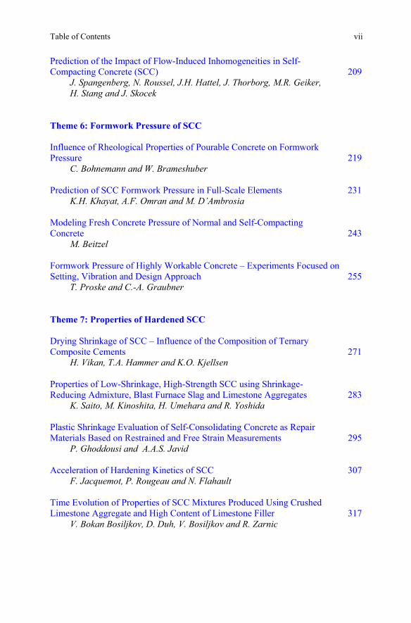
Table of Contents vii
Prediction of the Impact of Flow-Induced Inhomogeneities in Self-Compacting Concrete (SCC) 209
J. Spangenberg, N. Roussel, J.H. Hattel, J. Thorborg, M.R. Geiker, H. Stang and J. Skocek
Theme 6: Formwork Pressure of SCC Influence of Rheological Properties of Pourable Concrete on Formwork Pressure 219 C. Bohnemann and W. Brameshuber Prediction of SCC Formwork Pressure in Full-Scale Elements 231 K.H. Khayat, A.F. Omran and M. D’Ambrosia Modeling Fresh Concrete Pressure of Normal and Self-Compacting Concrete 243 M. Beitzel Formwork Pressure of Highly Workable Concrete – Experiments Focused on Setting, Vibration and Design Approach 255 T. Proske and C.-A. Graubner Theme 7: Properties of Hardened SCC Drying Shrinkage of SCC – Influence of the Composition of Ternary Composite Cements 271 H. Vikan, T.A. Hammer and K.O. Kjellsen Properties of Low-Shrinkage, High-Strength SCC using Shrinkage- Reducing Admixture, Blast Furnace Slag and Limestone Aggregates 283 K. Saito, M. Kinoshita, H. Umehara and R. Yoshida Plastic Shrinkage Evaluation of Self-Consolidating Concrete as Repair Materials Based on Restrained and Free Strain Measurements 295 P. Ghoddousi and A.A.S. Javid Acceleration of Hardening Kinetics of SCC 307 F. Jacquemot, P. Rougeau and N. Flahault Time Evolution of Properties of SCC Mixtures Produced Using Crushed Limestone Aggregate and High Content of Limestone Filler 317 V. Bokan Bosiljkov, D. Duh, V. Bosiljkov and R. Zarnic
Table of Contents viii
Effect of Freezing-Thawing Cycles on the Resistance of Self-Consolidating Concrete to Sulfate Attack 329
M.T. Bassuoni and M. Soneb
Theme 8: Bond Strength of SCC Bond Behaviour and Shear Capacity of Self-Compacting Concrete 343 V. Boel, P. Helincks, P. Desnerck and G. De Schutter Top-Bar Effect in Self-Compacting Concrete Elements 355 K.G. Trezos, I.P. Sfikas, M.S. Palmos and E.K. Sotiropoulou Effect of Rheology of SCC on Bond Strength of Ribbed Reinforcement Bars 367 L.N. Thrane, C. Pade, C. Idzerda, and M. Kaasgaard Development Length of Carbon-Fiber-Reinforced Polymer Bars in Self-Consolidating Concrete 379 S. Krem and K. Soudki Theme 9: Design and Performance of Fiber-Reinforced SCC Design with Highly Flowable Fiber-Reinforced Concrete: Overview of the Activity of fib TG 8.8 395 L. Ferrara, S. Grünewald and F. Dehn Fiber-Reinforced Cementitious Materials: From Intrinsic Isotropic Behavior to Fiber Alignment 407 L. Martinie and N. Roussel Flow-Induced Fiber Orientation in SCSFRC: Monitoring and Prediction 417 L. Ferrara, N. Tregger and S.P. Shah Shear Behavior of Self-Compacting Concrete and Fiber-Reinforced Concrete Push-Off Specimens 429 E. Cuenca and P. Serna Long-Term Behaviour of Fiber-Reinforced Self-Compacting Concrete Beams 439 N. Buratti, C. Mazzotti and M. Savoia Author Index 451 RILEM Publications 453
Preface Dear Colleagues, We are pleased to organize the Sixth International RILEM Symposium on SCC and the Fourth North-American Conference on the Design and Use of SCC, held on Sept 26-29, 2010 in Montreal, Quebec, Canada. The RILEM series of symposia started in 1999 in Stockholm, followed by Tokyo in 2001, Reykjavik in 2003, Chicago in 2005, and Ghent in 2007 with a steadily increasing number of papers, participants, and interest from across the globe. Due to the growing success of SCC, regional conferences have been organized, such as the North-American Conference on the Design and Use of SCC held in Chicago in 2002, 2005, and 2008; the International Symposium on Design, Performance and Use of SCC held in Changsa, China in 2005 and in Beijing, China in 2009; as well as the 2nd International Conference on Advances in Concrete Technology in the Middle East: SCC held in Abu Dhabi in 2009. It can be concluded that these regional Conferences and Symposia were highly successful and reached a far more international audience than anticipated. Nearly 100 papers were submitted for these proceedings from which the International Scientific Committee selected 37 contributions covering a wide range of timely and original subjects from around the world. We would like to acknowledge the input of the International Scientific Committee for providing critical input to guarantee high quality of these peer-reviewed proceedings. We invite you to explore a wealth of information in the electronic proceedings. Topics covered in this conference include SCC Mix Design, Chemical Admixtures, Rheology and Workabilty, Production and Placement, Flow Modeling, Formwork Pressure, Hardened Properties, Bond Strength, Fiber-Reinforced SCC, Economics, Worker's Health, Environmental Benefits, and Case Studies. These papers reflect significant advances made in research, design, and implementation of SCC worldwide during the last years. Nearly 130 papers will be presented during the three parallel sessions in addition to other papers discussed during the poster session at the conference. We would like to greatly acknowledge all the Authors for sharing their expertise and knowledge as well as our Sponsors for their generous support that is critical for the success of the conference. Special thanks go to the Honorary Advisory Committee and the International Technical Committee for their advice and help in promoting the conference.
ix

Preface x
We would like to thank the Organizers of this conference: l’Université de Sherbrooke, RILEM, la fédération internationale du béton (fib), the Center for Advanced Cement Based Materials (ACBM), and le Centre de Recherche sur les Infrastructures en Béton (CRIB) as well as the Local Organizing Committee for their diligent work and commitment to bring this conference to great success! The Editors, Kamal Henri Khayat Dimitri Feys Université de Sherbrooke, Canada September, 2010
Conference Committees Conference Chair K.H. Khayat, Université de Sherbrooke, Canada Honorary Advisory Committee A. Skarendahl, Sweden, chair of SCC 1999, Stockholm H. Okamura, Japan, chair of SCC 2001, Tokyo O. Wallevik, Iceland, chair of SCC 2003, Reykjavik S. Shah, USA, chair of SCC 2005 and SCC 2008, Chicago G. De Schutter, chair of SCC 2007, Ghent International Technical Committee O. Wallevik, IBRI, Iceland (chair) A. Bentur, Technion, Israel M. Geiker, Technical University of Denmark, Denmark T.A. Hammer, SINTEF, Norway J. Kim, Fosroc, South Korea R. Munn, University of New South Wales, Australia S. Nagataki, Aichi Institute of Technology, Japan M. Ouchi, Kochi University, Japan J. Walraven, Delft University, The Netherlands P. Yan, Tsinghua University, China International Scientific Committee G. De Schutter, Ghent University, Belgium (co-chair) N. Roussel, LCPC, France (co-chair) H. Abdelgader, Al-fateh University, Lybia G. Agranati, Politécnica de Madrid, Spain S. Amziane, Université Blaise-Pascal, France E. Attiogbe, BASF Construction Chemicals, USA C. Bédard, The Euclid Chemical Company, Canada
xi

Conference Committees xii
H. Beitzel, FH Trier, Germany P. Billberg, CBI, Sweden B. Blair, Lafarge North America, USA W. Brameshuber, University Aachen, Germany F. Cussigh, Vinci Construction, France J. Daczko, BASF Construction Chemicals, USA Y. Deshpande, Michigan Technological University, USA P. Domone, University College London, UK L. Ferrara, Politecnico di Milano, Italy C. Ferraris, National Institute of Standards and Technology, USA R. Ferron, University of Texas at Austin, USA R. Flatt, Sika, Switzerland J.V. Gruber, Bechtel Power Corporation, USA S. Grünewald, Hurks Beton / TU Delft, the Netherlands A. Kanellopoulos, University of Cyprus, Cyprus M. Khrapko, CBE Consultancy, New Zealand E. Koehler, W.R. Grace & Co., USA M. Lachemi, Ryerson University, Canada D. Lange, University of Illinois, USA C. Lanos, Université de Rennes 1, France A. Leemann, EMPA, Switzerland D. Ludirdja, Vulcan Materials Company, USA P. Lura, EMPA, Switzerland C. Mazzotti, University of Bologna, Italy C.V. Nielsen, Danish Technological Institute, Denmark C. Ozyildirim, Virginia Transportation Research Council, USA M. Pagé, Handy Chemicals, Canada A. Perrot, Université de Bretagne Sud, France B. Persson, Lund Institute of Technology, Sweden A.K. Schindler, Auburn University, USA W. Schmidt, BAM Berlin, Germany C. Shi, Hunan University, China K. Sideris, Democritus University of Thrace, Greece K.R. Sompura, Sika Corporation, USA M. Sonebi, Queen's University, Belfast, UK A. Tagnit-Hamou, Université de Sherbrooke, Canada C. Talbot, Omya Inc,, USA L.N. Thrane, Danish Technological Institute, Denmark F. Toussaint, Pôle technologique Lafarge, France M. Vachon, ESSROC, USA K. van Breugel, TUDelft, The Netherlands S. Vanikar, Federal Highway Administration, USA G. Ye, TUDelft, The Netherlands W. Zhu, University of the West of Scotland, Paisley, UK

Conference Committees xiii
Local Organizing Committee K.H. Khayat, Université de Sherbrooke, Canada (chair) O. Bonneau, Université de Sherbrooke, Canada G. Breton, Université de Sherbrooke, Canada C. Couture, Université de Sherbrooke, Canada Y. Denommé, Handy Chemicals, Canada D. Feys, Université de Sherbrooke, Canada R. Gagné, Université de Sherbrooke, Canada G. Lemieux, The Euclid Chemical Company, Canada B. Tighiouart, Université de Sherbrooke, Canada A. Yahia, Université de Sherbrooke, Canada


Theme 1: Mix Design for SCC
Design and Flow of Powder-type SCC with Crushed Aggregates Andreas Huss1 and Hans W. Reinhardt2 1 Materialprüfungsanstalt Universität Stuttgart, Germany 2 Department of Construction Materials, University of Stuttgart, Germany Abstract. The paper describes a new approach to determine the volume of the cement paste required to produce SCC irrespective of the granulometric characteristics of the aggregate. A test vessel has been designed which enables the determination of the void ratio of the aggregate and the necessary paste volume. The method has been applied to various aggregate (crushed quartz porphyry, crushed muschelkalk, gravel, fluvial sand). SCC mixtures have been designed according to the new approach, and it turned out that it has a good predictive potential as the mixture composition is concerned. Introduction A certain amount of cement paste is required to produce powder type SCC. This amount largely depends on the granulometric characteristics of the aggregates used. The amount of cement paste required to produce SCC is usually determined empirically on the basis of fresh concrete tests, or is assumed on the basis of the experience gained so far (see e.g. [1-3[3]). Since this situation is not satisfying, a method to determine the required cement paste volume which is not purely empirical has been developed, which is termed aggregate-packing test (APT). Void Ratio and Amount of Cement Paste Required As central point of the research, a method and a test vessel were developed to
CP,req) required for powder
larger than 0.125 mm in size in the composition in which it is to be used in the
directly, including any influence that may result from the granulometric
3
determine experimentally the amount of cement paste (V
K.H. Khayat and D. Feys (eds.), Design, Production and Placement
type SCC. In this process, the aggregate to be used in the SCC is examined
of Self-Consolidating Concrete, RILEM Bookseries 1,
characteristics of the aggregate. The method examines the aggregate fractions
DOI 10.1007/978-90-481-9664-7_1, © RILEM 2010

A. Huss and H.W. Reinhardt
concrete. For this purpose, a wetted, homogenized sample of the aggregate is fed into the test vessel (Figure 1) up to its top edge, without compaction.
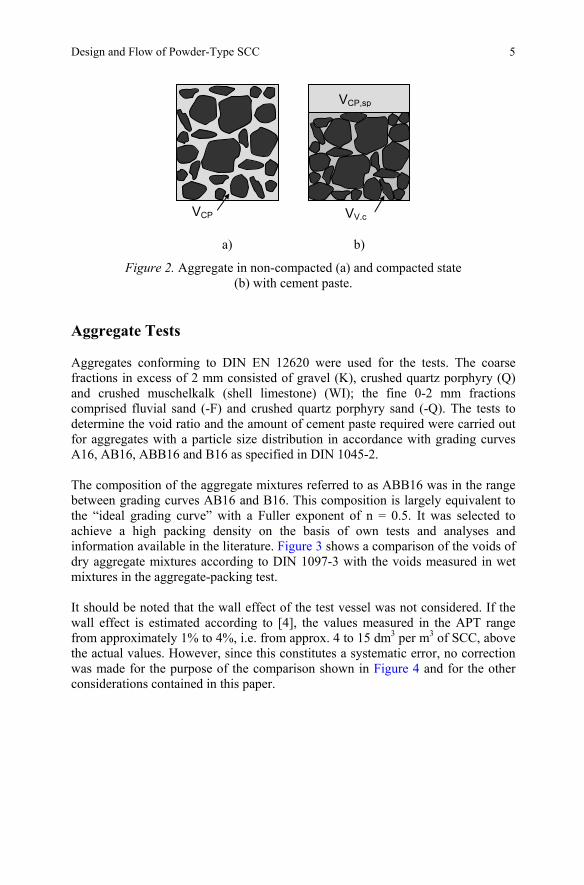
Figure 1. Test vessel, left: cross-section, right: picture. The vessel is then flooded with water from its bottom up to the top edge. The sample collapses during flooding and settles in a loose arrangement as a result of the reduction in, or elimination of, the friction between the particles and due to the mass of the aggregate. Following a saturation period, the water is siphoned off again through the bottom vessel section under controlled conditions. In the investigations presented in this article, the settlement condition of the aggregate mixture after water discharge is referred to as “non-compacted”. In this condition, the amount of water physically bound in the aggregate is determined (VW,nc) by weighing. In the next step, the aggregate is compacted under a defined load of 1.972 kg (≙ 3.1 kPa) by vibration, and the total volume (solids and voids) of the compacted aggregate (VA,c) is determined geometrically, as well as the void volume in compacted state (VV,c) via the concentration of solids. The concentration of solids is calculated using the particle volume VA (= mA /ρA) and the volume of the compacted aggregate VA,c. The amount of cement paste required to produce SCC (VCP,req) in cubic meters per cubic meter of SCC is calculated using Eqn. (1). VCP,req/VSCC = (VV,c + VCP,sp)/VSCC = (1 – VA/VA,c) + VW,nc/VA,c (1) Figure 2 shows the two situations. Figure 2a illustrates the non-compacted state with cement paste around the grains and in the voids. Figure 2b illustrates the state of the compacted aggregate with the cement paste in the remaining voids (VV,c) and the surplus cement paste (VCP,sp) which is necessary in order to cause self-compactibility.
4
Design and Flow of Powder-Type SCC
a) b)
Figure 2. Aggregate in non-compacted (a) and compacted state (b) with cement paste.
Aggregate Tests Aggregates conforming to DIN EN 12620 were used for the tests. The coarse fractions in excess of 2 mm consisted of gravel (K), crushed quartz porphyry (Q) and crushed muschelkalk (shell limestone) (WI); the fine 0-2 mm fractions comprised fluvial sand (-F) and crushed quartz porphyry sand (-Q). The tests to determine the void ratio and the amount of cement paste required were carried out for aggregates with a particle size distribution in accordance with grading curves A16, AB16, ABB16 and B16 as specified in DIN 1045-2. The composition of the aggregate mixtures referred to as ABB16 was in the range between grading curves AB16 and B16. This composition is largely equivalent to the “ideal grading curve” with a Fuller exponent of n = 0.5. It was selected to achieve a high packing density on the basis of own tests and analyses and information available in the literature. Figure 3 shows a comparison of the voids of dry aggregate mixtures according to DIN 1097-3 with the voids measured in wet mixtures in the aggregate-packing test. It should be noted that the wall effect of the test vessel was not considered. If the wall effect is estimated according to [4], the values measured in the APT range from approximately 1% to 4%, i.e. from approx. 4 to 15 dm3 per m3 of SCC, above the actual values. However, since this constitutes a systematic error, no correction was made for the purpose of the comparison shown in Figure 4 and for the other considerations contained in this paper.
VCP,sp
VV,cVCP
5

A. Huss and H.W. Reinhardt
200
250
300
350
400
450
A AB ABB B A AB ABB B A AB ABB B A AB ABB B
Grading curve
VV,nc
VV,EN
VV,c
VV,EN,c
K-F
Q-F WI-FQ-Q
Voi
d ra
tion
[dm
³/m³]
Figure 3. Void ratios of aggregate mixtures K-F; Q-F; WI-F and Q-Q in the case of grading curve variation. Non-compacted (VV,nc) and compacted (VV,c), as well as to the dry aggregate mixture on the basis of DIN EN 1097-3, non-compacted (VV,EN)
and compacted (VV,EN,c).
0.060
0.080
0.100
0.120
0.140
Aggregate
VW
,nc/V
A,c
[m³/m
³]
A16 (0/4: 36%) 0.091 0.083 0.078 0.086AB16 (0/4: 45%) 0.094 0.103 0.094 0.113ABB16 (0/4: 51%) 0.106 0.109 0.106 0.119B16 (0/4: 56%) 0.109 0.118 0.109 0.123
K-F Q-F WI-F Q-Q
Figure 4. Physically bound water (VW,nc)/volume of aggregate mixture (VA,c),
tested with the aggregate-packing test (APT) method whilst varying the grading curve.
6

Design and Flow of Powder-Type SCC
In the tests carried out, a larger void ratio was found in the aggregate-packing test than in the dry aggregate mixture test on the basis of DIN EN 1097-3. This outcome is attributed to the varying boundary conditions of the testing methods and to the fact that the fines fraction below 0.125 mm is missing in the APT method. In addition, it is assumed that the aggregates tested in dry condition segregate when being fed into the test vessel, and during compaction. This became particularly apparent for the tested aggregate that included crushed sand (-Q), where the void volume decreased much more significantly during compaction in dry condition as a result of the trickling-down fine particles, compared to aggregate tested in wet condition. For this reason, this paper uses the void volume VV,c determined in the APT in compacted condition as a parameter in Eqn. (1) to calculate the void volume for a zero cement paste layer thickness. The amount of cement paste required for the production of SCC (VCP,req) was determined on the basis of the results of the aggregate-packing test, using Eqn. (1). The volumes shown in Figure 4 have been determined using the amount of physically bound water during the APT. As expected, these volumes increase along with a higher fines ratio, i.e. in line with the increase in the aggregate surface. Although this ability to bind water mainly depends on the fines ratio, the most unfavorably shaped crushed quartz porphyry (Q) are clearly visible (Figure 4) because of the higher amount of water bound in the AB, ABB and B mixtures, in which the same fluvial sand (-F) was used. The particle surface of crushed sand (-Q), which is significantly higher than that of fluvial sand, is considered the main cause of the higher water-binding capacity of the Q-Q aggregate mixture tested.
0,200
0,250
0,300
0,350
0,400
0,450
0,500
Volu
me
[m³/m
³]
A16 (0/4: 36 %) 0,403 0,419 0,406 0,434AB16 (0/4: 45 %) 0,356 0,381 0,367 0,449ABB16 (0/4: 51 %) 0,364 0,395 0,376 0,455B16 (0/4: 56 %) 0,364 0,398 0,381 0,454A16 0,312 0,335 0,329 0,349AB16 0,262 0,282 0,273 0,335ABB16 0,259 0,286 0,271 0,337B16 0,254 0,281 0,272 0,331
K-F Q-F WI-F Q-Q
V V,c
V CP,
req
Aggregate
Figure 5. Amount of cement paste required (VCP,req) = void ratio in compacted
condition (VV,c) + (VW,nc)/(VA,c) according to Figure 4, tested with the aggregate-packing test (APT) whilst varying the grading curve.
7
A. Huss and H.W. Reinhardt
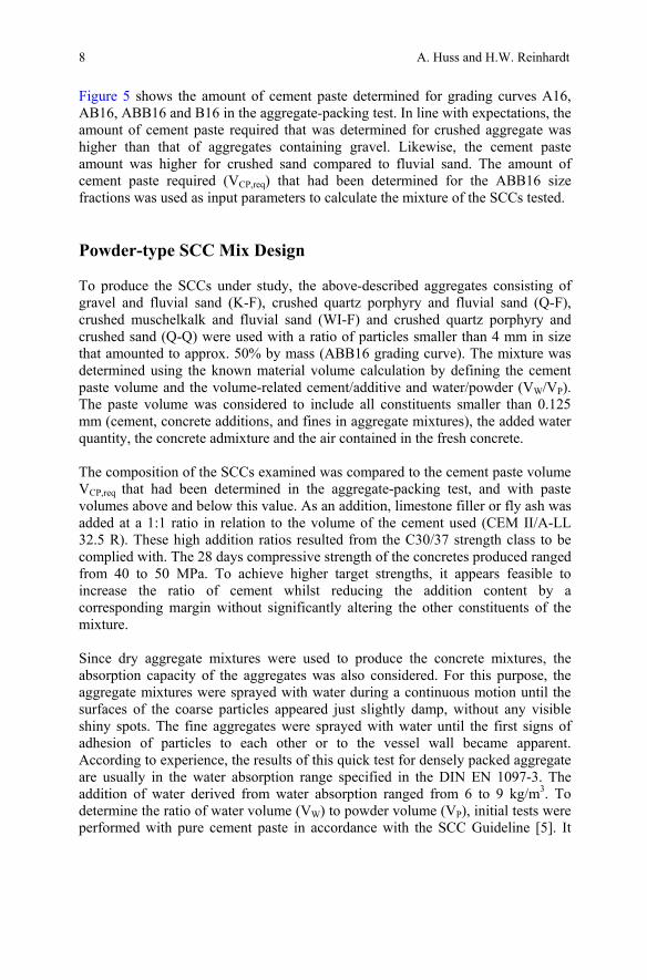
Figure 5 shows the amount of cement paste determined for grading curves A16, AB16, ABB16 and B16 in the aggregate-packing test. In line with expectations, the amount of cement paste required that was determined for crushed aggregate was higher than that of aggregates containing gravel. Likewise, the cement paste amount was higher for crushed sand compared to fluvial sand. The amount of cement paste required (VCP,req) that had been determined for the ABB16 size fractions was used as input parameters to calculate the mixture of the SCCs tested. Powder-type SCC Mix Design To produce the SCCs under study, the above-described aggregates consisting of gravel and fluvial sand (K-F), crushed quartz porphyry and fluvial sand (Q-F), crushed muschelkalk and fluvial sand (WI-F) and crushed quartz porphyry and crushed sand (Q-Q) were used with a ratio of particles smaller than 4 mm in size that amounted to approx. 50% by mass (ABB16 grading curve). The mixture was determined using the known material volume calculation by defining the cement paste volume and the volume-related cement/additive and water/powder (VW/VP). The paste volume was considered to include all constituents smaller than 0.125 mm (cement, concrete additions, and fines in aggregate mixtures), the added water quantity, the concrete admixture and the air contained in the fresh concrete. The composition of the SCCs examined was compared to the cement paste volume VCP,req that had been determined in the aggregate-packing test, and with paste volumes above and below this value. As an addition, limestone filler or fly ash was added at a 1:1 ratio in relation to the volume of the cement used (CEM II/A-LL 32.5 R). These high addition ratios resulted from the C30/37 strength class to be complied with. The 28 days compressive strength of the concretes produced ranged from 40 to 50 MPa. To achieve higher target strengths, it appears feasible to increase the ratio of cement whilst reducing the addition content by a corresponding margin without significantly altering the other constituents of the mixture. Since dry aggregate mixtures were used to produce the concrete mixtures, the absorption capacity of the aggregates was also considered. For this purpose, the aggregate mixtures were sprayed with water during a continuous motion until the surfaces of the coarse particles appeared just slightly damp, without any visible shiny spots. The fine aggregates were sprayed with water until the first signs of adhesion of particles to each other or to the vessel wall became apparent. According to experience, the results of this quick test for densely packed aggregate are usually in the water absorption range specified in the DIN EN 1097-3. The addition of water derived from water absorption ranged from 6 to 9 kg/m3. To determine the ratio of water volume (VW) to powder volume (VP), initial tests were performed with pure cement paste in accordance with the SCC Guideline [5]. It
8
Design and Flow of Powder-Type SCC
turned out, however, that this approach was not helpful when it came to designing a large number of different mixtures. One of the difficulties encountered was the issue of how to reflect the powder content in the aggregate. In addition, an incremental development of the mix design through the determination of the amount of water required (cement and addition), cement paste and mortar tests and fresh concrete testing would have been very complex. For this reason, the mix designs were based on approximate values for the VW/VP that were taken from the literature (e. g. [1-3]) and from own preliminary tests with a Portland limestone cement (CEM II/A-LL 32.5 R) and fly ash (FA) or limestone filler (LF). These values were then used to calculate the mixture compositions. For the mix designs investigated, the ratios selected amounted to VW/VP = 0.88 and VW/VP = 0.90 for limestone filler and fly ash, respectively. The extent to which the selected water-powder ratios were suitable to produce a suspension was tested for specific mixtures by measuring the “shear resistance” during the production of fresh concrete. In this procedure, the amount of water required for the conversion of the mixture (consisting of cement, addition and mineral aggregate) to a suspension was determined in an experimental setup. This volume was termed the minimum amount of water (wmin) and was derived from the “shear resistance” curve of the aggregate, which was indirectly captured via the input power of the compulsory mixer [6]. Own experience has shown that any water volume in excess of the minimum amount is tolerable as long as there are no signs of segregation (bleeding) of the fresh concrete, for instance in the form of “water shifting” occurring during the slump test. It is not possible, however, to go below the minimum amount of water since this would no longer provide the conditions under which a suspension, and thus SCC, can be produced. Only when the minimum amount of water wmin has been exceeded will it be possible to produce a SCC from the suspension by adding a plasticizer. The measurement of “shear resistance” depending on water addition provides a quick and convenient method to determine the amount of water required for SCC. The following fresh concrete parameters of the SCCs were measured [7]: • Slump flow with and without J-ring (sfJ; sf) • Blocking tendency in accordance with pr EN 12350-12 across the difference
in height within/outside the J-ring (blocking step stJ) • V-funnel flow time (tV) in accordance with pr EN 12350-9 • Air void ratio in the 8 dm3 vessel in accordance with DIN EN 12350-7. A slump flow target value of 690 mm was defined. The V-funnel flow target value was defined as a range of 14 ± 3 s according to [1]. At a constant VW/VP, the
9
A. Huss and H.W. Reinhardt
degree of flow was set by the amount of added plasticizer alone. The scope of the tests did not include an optimization of the paste composition. The SCCs’ blocking tendency was determined visually and by the blocking step stJ during the slump test. From the literature, values of stJ ≤ 20 mm were taken as a criterion for non-blocking SCC. In the SCCs investigated, blocking was found when the actual cement paste volume was lower than the required paste volume VCP,req established in the aggregate-packing test. For the SCCs produced with crushed quartz porphyry sand (-Q), it was found that their V-funnel flow time tV equaled approx. 7 s, and was thus significantly lower than the 14 ± 3 s target range. Despite this short V-funnel flow time, no signs of sedimentation were identified at sawn-open concrete cylinders for the mixtures in which the paste volume exceeded the calculated paste volume by 15 or 20 dm3/m3. Due to the high amount of plasticizer used, some of the air void ratios determined during the tests were as low as 0.6% by volume in the SCCs with reduced paste content. The SCCs with a paste volume that corresponded to the paste volume VCP,req calculated in the APT showed a very good degree of self-compaction with air void ratios between 1.0% and 1.5% by volume. When the paste content was very low it was impossible to reliably reach the target range (sf approx. 690 mm, stJ ≤ 20 mm and tV = 14 ± 3 s) in the tests carried out by adjusting the amount of plasticizer alone. Nor was it possible, under these conditions, to produce a SCC on the basis of a visual assessment. Starting from a paste volume equivalent to the volume VCP,req determined in the APT, it was possible to produce SCCs with added FA and LF that met practical requirements. Summary and Outlook In summary, the following conclusions can be drawn from the above considerations and tests with regard to the mix design of powder-type SCC with ABB 0/16 aggregates: • The aggregate-packing test (APT) is a practice-oriented method to
determine the required paste volume (VCP,req) for powder type SCC. By testing the mineral aggregate to be used for concrete production directly, this method delivers an integral description of the granulometric characteristics of aggregates. When the required paste volume has been determined, the mix design can be reduced to the known material volume calculation.
• The fact that the paste volume required for SCC production can be determined in the aggregate-packing test (APT) makes it possible to focus on the optimization of the cement paste. In this regard, the measurement of the power of the laboratory mixer made in the course of the tests has proven
10

Design and Flow of Powder-Type SCC
to be a quick and accurate method to determine the required minimum amount of water. Starting from the paste volume and minimum amount of water required, SCCs can be optimized in a targeted fashion, especially with respect to the selection and dosing of the plasticizer.
• Tests that are currently being carried out with other sands should verify the findings arrived at to date. In parallel, the practical feasibility of the proposed design concept in the production of SCC at the ready-mixed concrete plant is to be investigated.
References [1] Lemmer, C. (2003), A production approach for SCC as derived from
experimental studies, PhD Thesis, Technische Universität Darmstadt (in German).
[2] Marquardt, I. (2002), A mixing concept for SCC based on the volume parameters and the water demand of the constituent elements, PhD Thesis, University Rostock, Bull. 7 of Faculty of Civil Engineering, (in German).
[3] Kordts, S. (2005), Production and control of workability properties of SCC, PhD Thesis, Technische Universität Berlin (in German).
[4] Sedran, T. and de Larrard, F. (1999), Optimization of self compacting concrete thanks of packing model. PRO 7: 1st International RILEM Symposium on Self-Compacting Concrete, Å. Skarendahl and Ö. Petersson (Eds.), pp. 321-332.
[5] German Association of Structural Concrete (2003), Guideline for self-compacting concrete (in German).
[6] Huss, A. and Reinhardt, H.W. (2009), Powder-type SCC with crushed mineral aggregates. Concrete Plant + Precast Technology, vol. 75, n. 8, pp. 4-12 and n. 9, pp. 22-34.
[7] Pade, C. (2005), Test methods for SCC, Danish Technological Institute, Denmark.
11

“Structural Design with Flowable Concrete” - A fib-Recommendation for Tailor-Made Concrete Steffen Grünewald1, Liberato Ferrara2 and Frank Dehn3 1 Delft University of Technology/Hurks Beton, The Netherlands 2 Politecnico di Milano, Italy 3 University of Leipzig/MFPA Leipzig, Germany
Abstract. Flowable concrete (either compacted with some vibration or self-compacting) is becoming a widely applied building material. Due to its flowable nature, reinforcing bars can become an obstacle, mixture components may float or segregate and the casting technique determines the orientation of fibers, if any. An increasing range of components is available to optimize concrete concerning rheological and hardened state properties and for the application under consideration. Flowable concrete offers an extended range of engineering properties and the potential for product innovation. fib Task Group (TG) 8.8 “Structural Design with Flowable Concrete” started in 2009 to facilitate the use of innovative flowable materials for the design of concrete structures. Taking into account research findings and practical experience, the main objectives of fib TG 8.8 are to write a state-of-the-art report and recommendations on the structural design with flowable concrete. fib TG 8.8 considers three aspects of flowable concrete: material properties, production effects and structural boundary conditions. This paper discusses the scope of fib TG 8.8 concerning the characteristics and the potential of flowable concrete and presents related design standards. fib TG 8.8 aims at promoting the application of flowable concrete, improving and adapting the concrete design and the production technology and its implementation in guidelines and codes. Introduction Aim of fib Task Group 8.8 Design recommendations for flowable concrete will most likely be instrumental to promote and facilitate the application of highly flowable and self-compacting
K.H. Khayat and D. Feys (eds.), Design, Production and Placementof Self-Consolidating Concrete, RILEM Bookseries 1,
13
DOI 10.1007/978-90-481-9664-7_2, © RILEM 2010
S. Grünewald, L. Ferrara and F. Dehn
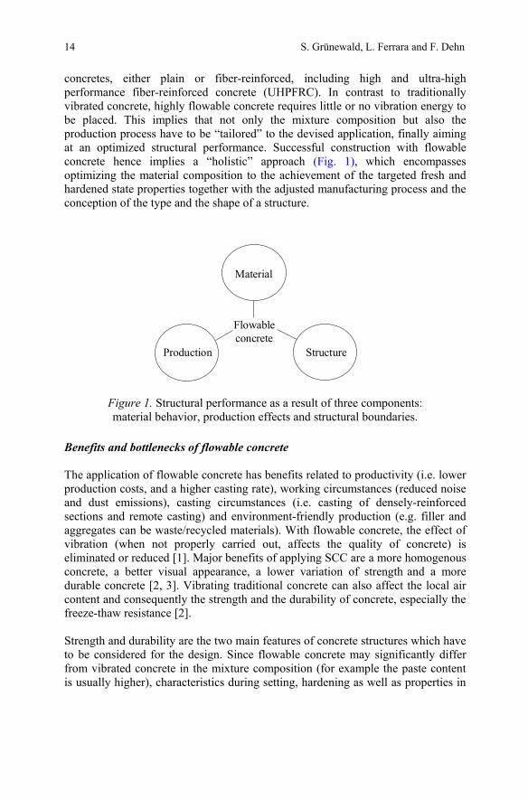
concretes, either plain or fiber-reinforced, including high and ultra-high performance fiber-reinforced concrete (UHPFRC). In contrast to traditionally vibrated concrete, highly flowable concrete requires little or no vibration energy to be placed. This implies that not only the mixture composition but also the production process have to be “tailored” to the devised application, finally aiming at an optimized structural performance. Successful construction with flowable concrete hence implies a “holistic” approach (Fig. 1), which encompasses optimizing the material composition to the achievement of the targeted fresh and hardened state properties together with the adjusted manufacturing process and the conception of the type and the shape of a structure.
Figure 1. Structural performance as a result of three components: material behavior, production effects and structural boundaries.
Benefits and bottlenecks of flowable concrete The application of flowable concrete has benefits related to productivity (i.e. lower production costs, and a higher casting rate), working circumstances (reduced noise and dust emissions), casting circumstances (i.e. casting of densely-reinforced sections and remote casting) and environment-friendly production (e.g. filler and aggregates can be waste/recycled materials). With flowable concrete, the effect of vibration (when not properly carried out, affects the quality of concrete) is eliminated or reduced [1]. Major benefits of applying SCC are a more homogenous concrete, a better visual appearance, a lower variation of strength and a more durable concrete [2, 3]. Vibrating traditional concrete can also affect the local air content and consequently the strength and the durability of concrete, especially the freeze-thaw resistance [2]. Strength and durability are the two main features of concrete structures which have to be considered for the design. Since flowable concrete may significantly differ from vibrated concrete in the mixture composition (for example the paste content is usually higher), characteristics during setting, hardening as well as properties in
Production
Material
Flowableconcrete
Structure
14
Structural Design with Flowable Concrete
the hardened state may be affected [4], which has to be adequately taken into account by designers and engineers. These issues will be addressed by fib TG 8.8. The aesthetical appearance of concrete often is an important criterion to decide what mixture will be applied for a structure. The type and the content of the powders and the composition of the paste mainly determine the color and the variation of color. Producing flowable concrete with fillers or pigments allows altering the color compared to a mixture that contains only cement as a powder. Flowable concrete usually contains a higher powder content and, if well-executed, fair-faced structures can be produced. The elimination of vibration or casting with a minimum of compaction energy largely reduces color inhomogeneities of the concrete surface. In this context, fib TG 8.8 intends to strongly cooperate with the new fib Task Group on “Aesthetics of Concrete Surfaces” (fib TG 8.9). Cussigh [5] and Desmyter [6] discussed the potential and the drawbacks of SCC; most aspects also describe the situation of flowable concrete in general. The need for high quality materials, for a higher accuracy of production equipment and for special formwork, higher material costs, stringent quality control requirements and a lack of standards possibly explain why the market-share of ready-mix SCC is low (Cussigh reported only 3% in France [5]) and why the precast industry may be more prone to implement SCC. With SCC, it is required to specify in advance where the supplier’s responsibility ends during production (i.e. concerning the surface appearance or blowholes). Higher material costs, an increased complexity and higher risks hinder a more widespread application of SCC in spite of many proven benefits. The difference in material costs of SCC compared to vibrated concrete decreases at increasing compressive strength. Applying ready-mix SCC involves more actors (i.e. owner, supplier, contractor) compared to the production of prefabricated elements with SCC. The fragmentation of the building industry and the prime focus on cost competition are main barriers for innovation [6]. Four issues have hence to be addressed to increase the market-share of the SCC-technology: to provide robust and reliable concrete mixtures, to involve industry in R&D-activities, to transfer knowledge and to develop accepted standards. Flowable concrete and SCC are important to further industrialize prefabricated and cast-in-place concrete construction, to improve the quality of concrete structures and to carry out projects more economically profitable. Flowable concrete with fibers Flowable fiber-reinforced concrete (FFRC) combines the benefits of flowable concrete in the fresh state and an enhanced performance of fiber-reinforced concrete (FRC) in the hardened state. By adding fibers to flowable concrete bar reinforcement can be replaced, crack widths reduced, the durability improved and the load bearing capacity of a structure increased. The size of the fibers relative to the rebar spacing affects the passing ability. By optimizing the mixture composition and balancing filling ability and segregation resistance, concrete can
15

S. Grünewald, L. Ferrara and F. Dehn
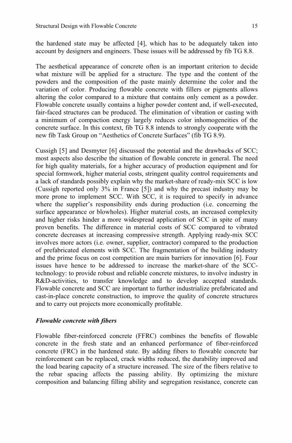
be self-compacting or highly flowable at a relative high fiber content. The fibers are not only carried but also transported in flowable concrete. The production circumstances can affect the orientation of fibers and the structural performance [7]. The potential of tailor-made concrete was demonstrated with recent developments like Engineered Cementitious Composites (ECC) and UHPFRC. Both concrete types can be self-compacting at high fiber contents (2-2.5 Vol.-%). Figure 2 compares different concrete types concerning the compressive strength and the fiber content. A relatively large area is not yet covered by standards and practical experience is lacking.
Figure 2. Common range of different concrete types concerning compressive strength and fiber content.
The application of optimized fiber-reinforced concrete might be an economic alternative for either typical SCC- or FRC-applications. Examples of applications with self-compacting fiber-reinforced concrete are slabs on grade, overlays, prefabricated prestressed beams, roof elements, sheet piles, tunnel segments, thin walls and façade panels. Without conventional reinforcement (rebars) any structural shape can be produced. The minimum thickness of elements without rebars is no longer determined by the concrete cover. Additional benefits are savings in mass, and the reduction of storage and transport volumes. The overall economic efficiency (time- and cost-effectiveness) of the construction process can be improved with flowable concrete. Due to the special characteristics of flowable FRC new fields of application can be explored.
200 150 100 50
compressive strength [MPa]
fiber content [Vol.-%]
T. fibre concrete
Special applications
ECC, plastic fibres
UHPC, French guideline
0,5
1,0
1,5
2,0
2,5
?
16

Structural Design with Flowable Concrete
Design recommendations for flowable concretes Numerous publications and conferences reflect the research efforts in the field of high-performance concrete during the past two decades. “High” performance has been achieved concerning i.e. durability, increased fracture toughness, improved deflection and strain hardening behavior, better flowability (even self-leveling behavior) and very high compressive and bond strengths. The research activities established trust in new materials. Concrete can be optimized to obtain a specific, tailor-made structural performance and as a consequence, new products or structures can be developed. Several commissions act worldwide to establish design recommendations for high-performance concrete. fib TG 8.8 will provide an overview of material characteristics including the influence of production and how this can be translated in structural design guidelines. Examples of recent standards and ongoing commissions for flowable concrete are: Self-compacting concrete • European Standards (additional rules: FprEN 206-9 [8]; test methods:
FprEN 12350 parts 8-12 [9]) • RILEM TC MPS: Mechanical Properties of Self-Compacting Concrete Fiber-reinforced concrete • fib Task Group 8.3: Fiber-reinforced concrete • Fiber-SCC: Concept for a Norwegian guideline [10] • ECC-recommendation, Japan [11] • RILEM TC 208-HFC: High Performance Fiber-Reinforced Cementitious
Comp. UHPC-recommendations • AFGC UHPFRC-recommendation, France [12] • UHPFRC-recommendation, Japan [13] • fib Task Group 8.6: Ultra-High Performance Fiber-Reinforced Concrete
fib TG 8.3 is preparing a design recommendation for FRC and fib TG 8.6 aims at completing in 2010 a design recommendation for UHPFRC. Important aspects of both recommendations will be included in the new Model Code, like the effect of the dispersion and the orientation of the fibers and a description of how material tests should be carried out. The material characteristics, the shape of an element and the applied production technique also determine the performance of a structure. The orientation of the fibers, which is affected by the flowability and the casting process, can be taken into account by testing specimens cut from a full-scale sample in different directions and positions.
17

S. Grünewald, L. Ferrara and F. Dehn
Characterization of Flowable Concretes Characteristics in the fresh state Flowable concrete, in comparison to conventional vibrated concrete, is characterized by a thicker paste layer around the aggregates that minimizes the friction of the grains and allows obtaining a low yield value that promotes the flow. For low strength classes, the relative water dosage (water to powder volume) of vibrated concrete usually is higher compared to flowable concrete at an equivalent strength. However, at a lower paste content and with a higher number of contact points connecting the aggregates, the flowability of vibrated concrete is lower. Vibrated high-strength concrete already can have high flowability due to high cement content and increased paste content. Midorikawa et al. [14] varied the grading and the content of sand in mortar (ratio s/m). The water to powder volume ratio (Vw/Vp) and the superplasticizer content (superplasticizer/powder by mass; SP/P) were adjusted until a flow diameter of 245+/-10 mm and a flow time of 10+/-1 s were obtained. The cone and the mortar funnel are described by Okamura et al. [15]. Figures 3 and 4 show the increase of the dosages of water and superplasticizer at increasing sand content (sands: Ar, Br and Cr), respectively.
Figure 3. Relationship between the fine aggregate volume and the water to powder
volume ratio (Vw/Vp) [14].
A higher flowability of concrete can be obtained by adjusting the rheology of the paste and the content of paste in concrete [16]. Once a certain paste content is exceeded (at a fixed composition of the paste), the flowability does not increase anymore since the flow behavior is already determined by the paste. Table I lists mixture compositions of a traditionally vibrated concrete (TC: C55/67) [17], 2 SCC’s (at a low and a high powder content) [18, 19], an ECC (with polyvinyl-alcohol fibers: P) [20] and a UHPFRC-mixture (with steel fibers: S) [21]. Mixture TC was designed for a slump higher than 15 cm.
18