Design Principles for the Development of Space Technology Maturation Laboratories Aboard the
428
Design Principles for the Development of Space Technology Maturation Laboratories Aboard the International Space Station Alvar Saenz-Otero, David W. Miller June 2005 SSL # 5-05 This work is based on the unaltered text of the thesis by Alvar Saenz-Otero submitted to the Department of Aeronautics and Astronautics in partial fullfilment of the requirements for the degreee of Doctor of Philosophy at the Massachusetts Institute of Technology. This report includes the main chapters and appendices on literature research. SSL report # 6-05 presents the technical appendices on the design of the SPHERES avionics, software, and communications sub- systems.
Transcript of Design Principles for the Development of Space Technology Maturation Laboratories Aboard the

Design Principles for the Development of Space Technology Maturation Laboratories Aboard the International Space Station
Alvar Saenz-Otero, David W. Miller
June 2005 SSL # 5-05
This work is based on the unaltered text of the thesis by Alvar Saenz-Otero submitted to the Department of Aeronautics and Astronautics in partial fullfilment of the requirements for the degreee of Doctor of Philosophy at the Massachusetts Institute of Technology. This report includes the main chapters and appendices on literature research. SSL report # 6-05 presents the technical appendices on the design of the SPHERES avionics, software, and communications sub-systems.

ii

Design Principles for the Development of Space Technology Maturation Laboratories Aboard the International Space Station
by
Alvar Saenz-Otero
Submitted to the Department of Aeronautics and Astronautics on June 2005 in partial fulfillment of the requirements for the degree of Doctor of Philosophy
in Aeronautics and Astronautics
ABSTRACT
This thesis formulates seven design principles for the development of laboratories which
utilize the International Space Station (ISS) to demonstrate the maturation of space tech-
nologies. The principles are derived from the lessons learned from more than two decades
of space technology research at the MIT Space Systems Laboratory and the existence of
unique resources aboard the ISS. The thesis provides scientists with a design framework
for new laboratories and an evaluation framework to responds to a call by the National
Research Council to institutionalize science activities aboard the ISS.
Experience from previous missions and research on the resources available at the ISS led
to the development of the SPHERES Laboratory for Distributed Satellite Systems (DSS),
which constitutes the experimental part of the thesis. SPHERES allows tests in a represen-
tative, risk-tolerant environment aboard the ISS to demonstrate metrology, control, and
autonomy algorithms for DSS. The implementation of ground-based and ISS-based facili-
ties permits incremental technology maturation by enabling iterative research; algorithms
can mature through multiple research cycles with increasing complexity. The SPHERES
Guest Scientist Program supports research by multiple scientists: since the Spring of 2000
SPHERES has enabled research on formation flight, communications requirements, mass
properties identification, autonomous rendezvous and docking, and tethered formation
flight.
iii

iv ABSTRACT
The design principles were formulated by first identifying the features of the SPHERES
laboratory which allow it to fulfill the MIT SSL Laboratory Design Philosophy and utilize
the ISS correctly, and then finding the applicability of these features to space technology
maturation research. The seven principles are: Principle of Iterative Research, Principle
of Enabling a Field of Study, Principle of Optimized Utilization, Principle of Focused
Modularity, Principle of Remote Operations and Usability, Principle of Incremental
Technology Maturation, and Principle of Requirements Balance. The design framework is
used to assess SPHERES and suggest a new design iteration which better satisfies the
design principles. The evaluation of SPHERES concludes that it is ready for operations
aboard the ISS, since the modular design of SPHERES allows most of the proposed design
changes to occur after the initial deployment.
Thesis Supervisor: David W. MillerAssociate Professor of Aeronautics and AstronauticsDirector, MIT Space Systems Laboratory
ACKNOWLEDGEMENTS
This work was performed primarily under contract F29601-97-K-0010/CLIN 9-10 withthe United States Air Force as part of the "Grand Challenges in Space: SPHERES" pro-gram. The work was also performed for contracts JPL1243444 "TPF Formation FlightTesting in the SPHERES Laboratory on the International Space Station" with the Califor-nia Institute of Technology Jet Propulsion Laboratory and Agmt. Dtd. 1/1/04 "SBIR PhaseII: SPHERES MOSR" with Payload Systems, Inc. The author gratefully thanks the spon-sors for their generous support that enabled this research. The author also thanks theUnited States Department of Defense Space Technologies Program Office for their sup-port of the flight program of SPHERES and the NASA Reduced Gravity Office for theirsupport of five SPHERES campaigns.
v

vi ACKNOWLEDGEMENTS

TABLE OF CONTENTS
Abstract . . . . . . . . . . . . . . . . . . . . . . . . . . . . . . . . . . . . . . . . iii
Acknowledgements . . . . . . . . . . . . . . . . . . . . . . . . . . . . . . . . . . . v
Table of Contents . . . . . . . . . . . . . . . . . . . . . . . . . . . . . . . . . . . vii
List of Figures . . . . . . . . . . . . . . . . . . . . . . . . . . . . . . . . . . . . . xi
List of Tables . . . . . . . . . . . . . . . . . . . . . . . . . . . . . . . . . . . . . xv
Acronym List . . . . . . . . . . . . . . . . . . . . . . . . . . . . . . . . . . . . xvii
Notation . . . . . . . . . . . . . . . . . . . . . . . . . . . . . . . . . . . . . . . . xx
Chapter 1. Introduction . . . . . . . . . . . . . . . . . . . . . . . . . . . . . . . 1
1.1 Motivation . . . . . . . . . . . . . . . . . . . . . . . . . . . . . . . . . . . . 31.1.1 NASA Technology Readiness Levels . . . . . . . . . . . . . . . . . . 6
1.2 Microgravity Research Facilities . . . . . . . . . . . . . . . . . . . . . . . . 9
1.3 Other Shared Remote Facilities . . . . . . . . . . . . . . . . . . . . . . . . 12
1.4 Thesis Roadmap . . . . . . . . . . . . . . . . . . . . . . . . . . . . . . . . 13
Chapter 2. Microgravity Research Aboard the ISS . . . . . . . . . . . . . . . 17
2.1 Issues and Challenges of Microgravity Research . . . . . . . . . . . . . . . 17
2.2 Research Areas of the International Space Station . . . . . . . . . . . . . . 212.2.1 Thesis Research Area Identification . . . . . . . . . . . . . . . . . . 22
2.3 Special Resources of the ISS . . . . . . . . . . . . . . . . . . . . . . . . . 26
Chapter 3. The MIT SSL Laboratory Design Philosophy . . . . . . . . . . . . 29
3.1 Definitions . . . . . . . . . . . . . . . . . . . . . . . . . . . . . . . . . . . 29
3.2 Characteristics of a Mature Technology Demonstration . . . . . . . . . . . 31
3.3 MIT SSL Previous Space Experiments . . . . . . . . . . . . . . . . . . . . 33
3.4 Features of a Laboratory for Space Technology Maturation . . . . . . . . . 343.4.1 Interactions Between the Features . . . . . . . . . . . . . . . . . . . 383.4.2 Facilitating the Iterative Research Process . . . . . . . . . . . . . . 413.4.3 Experiment Support Features . . . . . . . . . . . . . . . . . . . . . 46
vii

viii TABLE OF CONTENTS
3.4.4 Supporting Multiple Investigators . . . . . . . . . . . . . . . . . . . 523.4.5 Reconfiguration and Modularity . . . . . . . . . . . . . . . . . . . . 59
3.5 SSL Experiments and the Laboratory Design Philosophy . . . . . . . . . . 64
Chapter 4. The SPHERES Laboratory for DSS Research . . . . . . . . . . . 67
4.1 SPHERES Problem Statement . . . . . . . . . . . . . . . . . . . . . . . . 684.1.1 SPHERES Requirements . . . . . . . . . . . . . . . . . . . . . . . 684.1.2 ISS Constraints . . . . . . . . . . . . . . . . . . . . . . . . . . . . . 69
4.2 SPHERES Design Introduction . . . . . . . . . . . . . . . . . . . . . . . . 704.2.1 SPHERES Sub-systems . . . . . . . . . . . . . . . . . . . . . . . . 734.2.2 Further Information on SPHERES . . . . . . . . . . . . . . . . . . . 83
4.3 Meeting the MIT SSL Laboratory Design Philosophy . . . . . . . . . . . . 854.3.1 Facilitating the Iterative Research Process . . . . . . . . . . . . . . 874.3.2 Support of Experiments . . . . . . . . . . . . . . . . . . . . . . . . 1074.3.3 Supporting Multiple Investigators . . . . . . . . . . . . . . . . . . . 1344.3.4 Reconfiguration and Modularity . . . . . . . . . . . . . . . . . . . . 151
4.4 Summary . . . . . . . . . . . . . . . . . . . . . . . . . . . . . . . . . . . 165
Chapter 5. Microgravity Laboratory Design Principles . . . . . . . . . . . . . 169
5.1 Principle of Iterative Research . . . . . . . . . . . . . . . . . . . . . . . . 172
5.2 Principle of Enabling a Field of Study . . . . . . . . . . . . . . . . . . . . 176
5.3 Principle of Optimized Utilization . . . . . . . . . . . . . . . . . . . . . . 177
5.4 Principle of Focused Modularity . . . . . . . . . . . . . . . . . . . . . . . 180
5.5 Principle of Remote Operation & Usability . . . . . . . . . . . . . . . . . . 182
5.6 Principle of Incremental Technology Maturation . . . . . . . . . . . . . . . 183
5.7 Principle of Requirements Balance . . . . . . . . . . . . . . . . . . . . . . 186
5.8 The Design Principles, the Design Philosophy, and the ISS . . . . . . . . . 188
5.9 Science in the ISS to Date: Applicability of the Principles . . . . . . . . . . 190
5.10 Design Framework . . . . . . . . . . . . . . . . . . . . . . . . . . . . . . 1945.10.1 Step 1 - Identify a Field of Study . . . . . . . . . . . . . . . . . . . 1985.10.2 Step 2 - Identify Main Functional Requirements . . . . . . . . . . . 2015.10.3 Step 3 - Refine Design . . . . . . . . . . . . . . . . . . . . . . . . . 2155.10.4 Step 4 - Review Requirements and Design . . . . . . . . . . . . . . 219
5.11 ISS NGO Evaluation Framework . . . . . . . . . . . . . . . . . . . . . . . 221
5.12 Summary . . . . . . . . . . . . . . . . . . . . . . . . . . . . . . . . . . . 225

TABLE OF CONTENTS ix
Chapter 6. Assessment of SPHERES . . . . . . . . . . . . . . . . . . . . . . . 229
6.1 SPHERES Results to Date . . . . . . . . . . . . . . . . . . . . . . . . . . 2296.1.1 Current Programs . . . . . . . . . . . . . . . . . . . . . . . . . . . 2306.1.2 Future Programs . . . . . . . . . . . . . . . . . . . . . . . . . . . . 2336.1.3 Experimental Results . . . . . . . . . . . . . . . . . . . . . . . . . 236
6.2 Design Framework . . . . . . . . . . . . . . . . . . . . . . . . . . . . . . 2376.2.1 Step 1 - Identify a Field of Study . . . . . . . . . . . . . . . . . . . 2376.2.2 Step 2 - Identify Main Functional Requirements . . . . . . . . . . . 2416.2.3 Step 3 - Refine Design . . . . . . . . . . . . . . . . . . . . . . . . . 2566.2.4 Step 4 - Review Requirements and Design . . . . . . . . . . . . . . 2656.2.5 Design Framework Assessment Summary . . . . . . . . . . . . . . 269
6.3 Evaluation Framework . . . . . . . . . . . . . . . . . . . . . . . . . . . . 2716.3.1 ISS NGO Evaluation Summary . . . . . . . . . . . . . . . . . . . . 279
Chapter 7. Conclusions . . . . . . . . . . . . . . . . . . . . . . . . . . . . . . 281
7.1 Thesis Summary . . . . . . . . . . . . . . . . . . . . . . . . . . . . . . . . 281
7.2 Contributions . . . . . . . . . . . . . . . . . . . . . . . . . . . . . . . . . 303
7.3 Future Work . . . . . . . . . . . . . . . . . . . . . . . . . . . . . . . . . . 305
7.4 Concluding Remarks . . . . . . . . . . . . . . . . . . . . . . . . . . . . . 307
References . . . . . . . . . . . . . . . . . . . . . . . . . . . . . . . . . . . . . . . 309
Appendix A. NASA Technology Readiness Levels . . . . . . . . . . . . . . . . 321
Appendix B. Microgravity Research Facilities . . . . . . . . . . . . . . . . . . 325
B.1 3rd Party Ground-based Facilities . . . . . . . . . . . . . . . . . . . . . . . 325B.1.1 Flat Floors . . . . . . . . . . . . . . . . . . . . . . . . . . . . . . . 326B.1.2 Drop Towers . . . . . . . . . . . . . . . . . . . . . . . . . . . . . . 326B.1.3 Neutral Buoyancy Tanks . . . . . . . . . . . . . . . . . . . . . . . . 329B.1.4 Reduced Gravity Airplanes . . . . . . . . . . . . . . . . . . . . . . 331
B.2 Space Shuttle . . . . . . . . . . . . . . . . . . . . . . . . . . . . . . . . . 333
B.3 The International Space Station . . . . . . . . . . . . . . . . . . . . . . . . 337
B.4 Past Space-based Laboratories . . . . . . . . . . . . . . . . . . . . . . . . 340B.4.1 Sályut . . . . . . . . . . . . . . . . . . . . . . . . . . . . . . . . . 340B.4.2 US Skylab [Belew, 1977] . . . . . . . . . . . . . . . . . . . . . . . 341B.4.3 Space Lab [Emond, 2000] . . . . . . . . . . . . . . . . . . . . . . . 343B.4.4 MIR . . . . . . . . . . . . . . . . . . . . . . . . . . . . . . . . . . 344

x TABLE OF CONTENTS
Appendix C. Other Remote Research Facilities . . . . . . . . . . . . . . . . . 349
C.1 Antarctic Research . . . . . . . . . . . . . . . . . . . . . . . . . . . . . . 349
C.2 Ocean Research and Exploration . . . . . . . . . . . . . . . . . . . . . . . 355
Appendix D. The International Space Station . . . . . . . . . . . . . . . . . . 361
D.1 Objectives and Research Directions . . . . . . . . . . . . . . . . . . . . . . 361
D.2 Components of the ISS . . . . . . . . . . . . . . . . . . . . . . . . . . . . 363
D.3 ISS Facilities for Research . . . . . . . . . . . . . . . . . . . . . . . . . . 367D.3.1 ISS Modules for Research . . . . . . . . . . . . . . . . . . . . . . . 367D.3.2 ISS Resources for Research . . . . . . . . . . . . . . . . . . . . . . 371D.3.3 Multi-user Facilities . . . . . . . . . . . . . . . . . . . . . . . . . . 373
D.4 Engineering and Operational Challenges of the ISS . . . . . . . . . . . . . 375
Appendix E. MIT SSL Previous Microgravity Experiments . . . . . . . . . . 379
E.1 MODE & MODE Re-Flight . . . . . . . . . . . . . . . . . . . . . . . . . . 379
E.2 DLS . . . . . . . . . . . . . . . . . . . . . . . . . . . . . . . . . . . . . . 383
E.3 MACE & MACE-re-flight . . . . . . . . . . . . . . . . . . . . . . . . . . 384
Appendix F. SPHERES Avionics Design . . . . . . . . . . . . . . . . . . . . . 391
Appendix G. SPHERES Software Design . . . . . . . . . . . . . . . . . . . . . 393
Appendix H. SPHERES Communications . . . . . . . . . . . . . . . . . . . . 395
Appendix I. SPHERES Experimental Results . . . . . . . . . . . . . . . . . . 397
I.1 Results at the MIT SSL . . . . . . . . . . . . . . . . . . . . . . . . . . . . 397
I.2 Results aboard the KC-135 . . . . . . . . . . . . . . . . . . . . . . . . . . 399
I.3 Results at the MSFC Flat Floor . . . . . . . . . . . . . . . . . . . . . . . . 407

LIST OF FIGURES
Figure 1.1 Thesis research process . . . . . . . . . . . . . . . . . . . . . . . . . . 2
Figure 1.2 Discontinuity in complexity, risk, and cost at each TRL . . . . . . . . . 9
Figure 1.3 Thesis roadmap . . . . . . . . . . . . . . . . . . . . . . . . . . . . . 14
Figure 3.1 Overview of the scientific method by Gauch . . . . . . . . . . . . . . 44
Figure 4.1 The five flight-qualified SPHERES nano-satellites . . . . . . . . . . . 70
Figure 4.2 SPHERES operational concept . . . . . . . . . . . . . . . . . . . . . 71
Figure 4.3 SPHERES satellite . . . . . . . . . . . . . . . . . . . . . . . . . . . 73
Figure 4.4 SPHERES avionics overview . . . . . . . . . . . . . . . . . . . . . . 75
Figure 4.5 SPHERES software layers . . . . . . . . . . . . . . . . . . . . . . . 79
Figure 4.6 SPHERES operations overview . . . . . . . . . . . . . . . . . . . . . 81
Figure 4.7 SPHERES nano-satellite structural design . . . . . . . . . . . . . . . 84
Figure 4.8 Iterative research process for SPHERES . . . . . . . . . . . . . . . . 88
Figure 4.9 GSP iterative research loop . . . . . . . . . . . . . . . . . . . . . . . 91
Figure 4.10 MIT SSL on-site iterative research loop . . . . . . . . . . . . . . . . 93
Figure 4.11 MIT SSL off-site iterative research loop . . . . . . . . . . . . . . . . 94
Figure 4.12 ISS iterative research process . . . . . . . . . . . . . . . . . . . . . . 97
Figure 4.13 SPHERES programs composition . . . . . . . . . . . . . . . . . . . . 100
Figure 4.14 SPHERES satellites initialization . . . . . . . . . . . . . . . . . . . . 104
Figure 4.15 Accelerometer and gyroscope measurements in micro gravity . . . . . 110
Figure 4.16 Global metrology system time-of-flight distance measurements . . . . 112
Figure 4.17 Measuring the state vector with the layered metrology system . . . . . 113
Figure 4.18 Differential measurements between two satellites. . . . . . . . . . . . 114
Figure 4.19 Sample real-time and post-test data telemetry algorithms . . . . . . . 116
Figure 4.20 High priority scheduling of system timing and controller interrupts . . 122
Figure 4.21 Test synchronization via communications. . . . . . . . . . . . . . . . 123
Figure 4.22 Test synchronization to within 1ms . . . . . . . . . . . . . . . . . . . 124
Figure 4.23 SPHERES GUI for ground-based operations . . . . . . . . . . . . . . 126
Figure 4.24 ISS astronaut interface . . . . . . . . . . . . . . . . . . . . . . . . . 128
xi

xii LIST OF FIGURES
Figure 4.25 SCS interfaces to user code, DSP/BIOS, and hardware . . . . . . . . . 140
Figure 4.26 GSP simulation window . . . . . . . . . . . . . . . . . . . . . . . . . 144
Figure 4.27 SPHERES satellite expansion port face (without cover) . . . . . . . . 148
Figure 4.28 SPHERES expansion port design overview . . . . . . . . . . . . . . . 149
Figure 4.29 SPHERES -X "docking face" . . . . . . . . . . . . . . . . . . . . . . 155
Figure 4.30 FLASH memory map . . . . . . . . . . . . . . . . . . . . . . . . . . 163
Figure 5.1 The iterative research process . . . . . . . . . . . . . . . . . . . . . . 174
Figure 5.2 Smoothing TRL transitions . . . . . . . . . . . . . . . . . . . . . . . 186
Figure 5.3 Design principles application strategy . . . . . . . . . . . . . . . . . 195
Figure 5.4 General trend of cost J using cost function 5.1 . . . . . . . . . . . . . 201
Figure 5.5 Achieving effective iterations though flexible scheduling. . . . . . . . 205
Figure 5.6 Value curves for ISS unique resources . . . . . . . . . . . . . . . . . 210
Figure 5.7 Two paths to flight operations . . . . . . . . . . . . . . . . . . . . . . 213
Figure 6.1 Z-axis inertia estimate from ground-based tests . . . . . . . . . . . . 231
Figure 6.2 Sample results of docking algorithms at the MIT SSL . . . . . . . . . 232
Figure 6.3 Five satellite TPF maneuvers at the MSFC Flat Floor . . . . . . . . . 233
Figure 6.5 Artist’s conception of MOSR aboard the ISS . . . . . . . . . . . . . . 235
Figure 6.4 Two and three satellite tethered setups at the MSFC Flat Floor . . . . 235
Figure 6.6 Fractional cost of enabling multiple areas of study . . . . . . . . . . . 241
Figure 6.7 KC-135 iterative research loop . . . . . . . . . . . . . . . . . . . . . 245
Figure 6.8 MSFC Flat Floor iterative research loops . . . . . . . . . . . . . . . . 248
Figure 6.9 Effectiveness of iterations with SPHERES . . . . . . . . . . . . . . . 250
Figure 6.10 SPHERES Functional Requirements . . . . . . . . . . . . . . . . . . 267
Figure 7.1 SPHERES operations aboard the KC-135 RGA . . . . . . . . . . . . 290
Figure B.1 ZARM drop tower . . . . . . . . . . . . . . . . . . . . . . . . . . . . 328
Figure B.2 NASA Neutral Buoyancy Laboratory . . . . . . . . . . . . . . . . . . 329
Figure B.3 NASA KC-135 airplane and flight path . . . . . . . . . . . . . . . . . 332
Figure B.4 Space Shuttle payload bay and middeck . . . . . . . . . . . . . . . . 334
Figure B.5 The ISS on October 2002 . . . . . . . . . . . . . . . . . . . . . . . . 339
Figure B.6 US Skylab . . . . . . . . . . . . . . . . . . . . . . . . . . . . . . . . 342
Figure B.7 The MIR Space Station . . . . . . . . . . . . . . . . . . . . . . . . . 345

LIST OF FIGURES xiii
Figure C.1 Antarctic research stations . . . . . . . . . . . . . . . . . . . . . . . 350
Figure C.2 WHOI research vessels Knorr (left) and Alvin . . . . . . . . . . . . . 358
Figure D.1 The ISS at US Core Complete . . . . . . . . . . . . . . . . . . . . . . 364
Figure D.2 US Destiny laboratory . . . . . . . . . . . . . . . . . . . . . . . . . . 368
Figure D.3 US Centrifuge Accommodation Module . . . . . . . . . . . . . . . . 368
Figure D.4 US Truss Attachment Points (4) . . . . . . . . . . . . . . . . . . . . . 369
Figure D.5 Japanese Experiment Module . . . . . . . . . . . . . . . . . . . . . . 370
Figure D.6 Columbus Module . . . . . . . . . . . . . . . . . . . . . . . . . . . . 370
Figure E.2 MODE Structural Test Article with Alpha joint . . . . . . . . . . . . 381
Figure E.1 MODE Experiment Support Module w/ Fluid Test Article . . . . . . . 381
Figure E.3 DLS handhold and foot restraint . . . . . . . . . . . . . . . . . . . . 382
Figure E.4 MACE operations on shuttle mid-deck . . . . . . . . . . . . . . . . . 385
Figure E.5 MACE Experiment Support Module . . . . . . . . . . . . . . . . . . 385
Figure E.6 MACE operations aboard the ISS . . . . . . . . . . . . . . . . . . . . 389

xiv LIST OF FIGURES

LIST OF TABLES
TABLE 1.1 Sample of available facilities for m-g research . . . . . . . . . . . . . 10
TABLE 1.2 Sample of available m-g research facilities . . . . . . . . . . . . . . 11
TABLE 2.1 Research experiments of Expedition 6 . . . . . . . . . . . . . . . . . 23
TABLE 2.2 Special resources of the ISS that facilitate microgravity research . . . 28
TABLE 3.1 Summary of MIT SSL microgravity experiments . . . . . . . . . . . 34
TABLE 3.2 Interaction between the SSL Design Philosophy elements . . . . . . . 39
TABLE 3.3 Grouping of the SSL Design Philosophy features . . . . . . . . . . . 41
TABLE 3.4 Past Experiments and the philosophy features . . . . . . . . . . . . . 65
TABLE 4.1 SPHERES quantitative operational requirements . . . . . . . . . . . 72
TABLE 4.2 SPHERES satellite properties . . . . . . . . . . . . . . . . . . . . . 73
TABLE 4.3 SPHERES sub-systems . . . . . . . . . . . . . . . . . . . . . . . . . 74
TABLE 4.5 SPHERES sub-systems and the design philosophy . . . . . . . . . . 86
TABLE 4.4 Design for formation flight (FF) vs. design philosophy (Lab) . . . . . 86
TABLE 4.6 Satellite dynamics under actuation . . . . . . . . . . . . . . . . . . . 108
TABLE 4.7 Gyroscope specifications (BEI Gyrochip II) . . . . . . . . . . . . . . 109
TABLE 4.8 Accelerometer specifications (Honneywell Q-Flex QA-750) . . . . . 110
TABLE 4.9 SCS guest scientist interface modules . . . . . . . . . . . . . . . . . 141
TABLE 4.10 SPHERES implementation of a spacecraft bus . . . . . . . . . . . . . 153
TABLE 4.11 SPHERES bootloading process . . . . . . . . . . . . . . . . . . . . 164
TABLE 4.12 Summary . . . . . . . . . . . . . . . . . . . . . . . . . . . . . . . . 166
TABLE 5.1 Design Principles, the Laboratory Design Philosophy, and the ISS . . 189
TABLE 5.2 Experiments in Expedition 6 . . . . . . . . . . . . . . . . . . . . . . 191
TABLE 5.3 Summary of ISS special resources . . . . . . . . . . . . . . . . . . . 209
TABLE 5.4 Modularity criteria truth table . . . . . . . . . . . . . . . . . . . . . 216
TABLE 6.1 Summary of SPHERES Experimental Results . . . . . . . . . . . . . 236
TABLE 6.2 Areas of study supported by SPHERES . . . . . . . . . . . . . . . . 239
TABLE 6.3 Research iterations aboard the KC-135 . . . . . . . . . . . . . . . . 246
TABLE 6.5 Summary of operational environments and iterative research . . . . . 249
xv

xvi LIST OF TABLES
TABLE 6.4 MSFC flat floor iterations . . . . . . . . . . . . . . . . . . . . . . . 249
TABLE 6.6 SPHERES value from ISS resource utilization . . . . . . . . . . . . . 253
TABLE 6.7 Modularity of SPHERES . . . . . . . . . . . . . . . . . . . . . . . . 261
TABLE 7.1 Research facilities studied in the thesis . . . . . . . . . . . . . . . . . 283
TABLE 7.2 Benefits of the ISS for microgravity research . . . . . . . . . . . . . 286
TABLE B.1 Sample of available facilities for m-g research . . . . . . . . . . . . . 325
TABLE C.1 Major sub-systems of space and ocean research vehicles . . . . . . . 357
TABLE D.1 Originally planned multi-user facilities for the ISS . . . . . . . . . . 374
TABLE D.2 ISS Infrastructure Upgrades . . . . . . . . . . . . . . . . . . . . . . 378
TABLE I.1 Research conducted at the MIT SSL . . . . . . . . . . . . . . . . . . 397
TABLE I.2 KC-135 flight weeks and satellites operated . . . . . . . . . . . . . . 399
TABLE I.3 February 2000 flight results . . . . . . . . . . . . . . . . . . . . . . 400
TABLE I.4 March 2000 flight results . . . . . . . . . . . . . . . . . . . . . . . . 401
TABLE I.5 October 2001 flight results . . . . . . . . . . . . . . . . . . . . . . . 403
TABLE I.6 July/August 2002 flight results . . . . . . . . . . . . . . . . . . . . . 404
TABLE I.7 February 2003 flight results . . . . . . . . . . . . . . . . . . . . . . 405
TABLE I.8 November 2003 flight results . . . . . . . . . . . . . . . . . . . . . . 406
TABLE I.9 MSFC flat floor experiments . . . . . . . . . . . . . . . . . . . . . . 407

ACRONYM LIST
#D # dimensionsAFRL Air Force Research LaboratoriesANSI American National Standards InstituteAPI Application Programming InterfaceARD Autonomous Rendezvous and DockingASCII American Standard Code for Information InterchangeCDIO Conceive, Design, Implement, OperateCDR Critical Design ReviewCLK Hardware timer driven HWICOTS Commercial Off The ShelfCRC Cyclic Redundancy Codes (Checksum)CSA Canadian Space AgencyDARPA Defense Advanced Research Projects Agency DLS Dynamic Load Sensors experimentDoD Department of DefenseDOE Design of ExperimentsDOF Degree of FreedomDR2000 RFM Monolithics transceiver moduleDSP Digital Signal ProcessorDSP/BIOS Texas Instruments Real-time Operating System KernelDSS Distributed Satellite SystemESA European Space AgencyFDIR Fault Detection, Identification, and RecoveryFLASH Type of electrically erasable programmable read only memory (EEPROM)FPGA Field Programmable Gate ArrayGFLOPS Giga FLOPS (Billion Floating Point Operations Per Second)GIPS Giga (Billion) Instructions Per SecondGNC Guidance, Navigation, and ControlGPS Global Positioning SystemGSP Guest Scientist ProgramGUI Graphical User InterfaceHWI Hardware InterruptIDE Integrated Development EnvironmentIMU Inertial Measurement UnitIR InfraredISS International Space StationJPL Jet Propulsion LaboratoryJSC Johnson Spaceflight CenterKC-135 NASA’s reduced gravity airplaneLEO Low Earth Orbit
xvii

xviii ACRONYM LIST
LIB Larger is BestMACE Middeck Active Control ExperimentMBX Mailbox data transfer constructMCU Micro-Controller UnitMFLOPS Million Floating Point Operations Per SecondMIT Massachusetts Institute of TechnologyMLE Middeck Locker EquivalentMODE Middeck 0-gravity Dynamics ExperimentMOSR Mars Orbit Sample ReturnMSFC Marshall Space Flight CenterNASA National Aeronautics and Space AdministrationNASDA Japanese National Space Development AgencyNGO Non-Governmental OrganizationNIB Nominal is BetterNMP New Millennium ProgramNRC National Research CouncilPADS Position and Attitude Determination System (Metrology system)PC Personal ComputerPIP Pipe data transfer constructPIC Microchip PIC line of micro controllersPRD Periodic SWIPSI Payload Systems Inc.RAM Random Access MemoryRF Radio Frequency (wireless communications)RGA Reduced gravity airplaneRGO Reduced gravity office at NASA JSCRGP Reduced gravity programRSA Russian Space AgencyRTOS Real-Time Operating SystemRX Receive / ReceiverSCAR Special Committee for Antarctic ResearchSCS SPHERES Core Services software layerSEM Semaphore synchronization constructSIB Smaller is BestSMT375 Sundance Multiprocessor Technologies DSP board model 375SOH State of HealthSPECS Sub-millimeter Probe of the Evolution of Cosmic StructuresSPHERES Synchronized Position Hold Engage Re-orient Experimental SatellitesSSC Station Support Computer (ISS)SSL Space Systems LaboratorySSP Space Shuttle ProgramSTG Satellite-to-groundSTL Satellite-to-laptopSTP DoD Space Technology Programs OfficeSTS Satellite-to-satellite

ACRONYM LIST xix
STS-# Space Shuttle Mission #SWI Software InterruptTDMA Time Division Multiple AccessTPF Terrestrial Planet FinderTRL Technology Readiness LevelTSK Background Task (periodic or aperiodic)TX Transmit / TransmitterUS UltrasoundUART Universal Asynchronous Receiver Transmitter

xx NOTATION
NOTATION
° degree°C degrees Celsius°F degrees FahrenheitA Ampereb bitB byte (8 bits)cm centimeterdeg degreeF Faradft feetg gravity constant (9.8m/s2)h hourHz frequency in hertz (1/s)in inchkbps kilo bits per secondkg kilogram (mass)Mbps mega bits per secondMBps mega bytes per secondµ-g microgravityµg micro-g: one millionth of the gravity constant (9.8m/s2 x 10-6)µs microsecondΩ Ohmm metermin minutemo monthml millilitersmg milli-g: one thousand of the gravity constant (9.8m/s2 x 10-3)ms millisecondN Newtonnm nanometerpsi pounds per square inchrad radians secondV Volty yearW Watt

Chapter 1
INTRODUCTION
This thesis utilizes the lessons learned from the development of the SPHERES experiment
and other MIT Space Systems Laboratory (SSL) projects to define a set of design princi-
ples for developing facilities to conduct space technology research in the International
Space Station (ISS). The thesis follows the standard scientific process to define the princi-
ples. The objective of the thesis is to create a design methodology for the development of
microgravity laboratories which allows the maturation of space technologies. The objec-
tive is motivated from the lessons learned by the MIT SSL during the design and operation
of multiple space-based experiments and by a call by the National Aeronautics and Space
Administration (NASA) and the National Research Council (NRC) to define how to insti-
tutionalize research aboard the International Space Station (ISS). The thesis objectives
address the use of the ISS in two ways: the need of multiple researchers to access micro-
gravity conditions to cost-effectively mature technologies and to make the best possible
use of ISS resources. The hypothesis rests on the use of the MIT SSL Laboratory Design
Philosophy, which consists of a set of features desired from a laboratory identified through
the review of past experiences at the MIT SSL, and the correct utilization of existing
resources to mature space technology. The hypothesis states that by using this laboratory
design philosophy to develop projects to operate aboard the ISS, the resulting laboratory
environment facilitates the maturation of space technology in an ideal environment. The
SPHERES facility constitutes the experimentation. Based on the lessons learned from
building SPHERES, the laboratory design philosophy and the knowledge of the ISS envi-
1

2 INTRODUCTION
ronment were condensed into a set of design principles that characterize successful labora-
tory environments. Frameworks to apply the principles both at the design and evaluation
phases complete the results. The conclusions identify the ability of the principles to meet
the objective by analyzing the success of SPHERES as well as other experiments already
aboard the ISS. Figure 1.1 summarizes these steps of the scientific process (objective,
hypothesis, experimentation, results, and conclusion) as they are addressed in the thesis.
Objective:Create a design methodology for the development of microgravity laboratories for the research and maturation of space technologies.
Hypothesis:The conjunction of the International Space Station as a host and the MIT SSL Lab-oratory Design Philosophy as the design guidelines enable the development of a low-cost environment for the development and operation of facilities to conduct space technology research.
Experimentation:The SPHERES laboratory for distributed satellite systems has been developed fol-lowing the MIT SSL Design Philosophy for microgravity operations specifically aboard the ISS.
Results:The MIT SSL Design Philosophy and research on the characteristics and opera-tions of the ISS are condensed into a set of Design Principles that define the proper design of a research laboratory for the ISS.
Conclusion:While the availability of the ISS has not proved as efficient as originally desired, the Design Principles and corresponding frameworks do create a valid methodol-ogy for the development of microgravity research facilities which reduce both the cost and risk of maturating space technologies. Further, by following of these prin-ciples can allow facilities to benefit the research community even if not all opera-tional environments are available.
Figure 1.1 Thesis research process

Motivation 3
1.1 Motivation
Precision space systems are becoming increasingly difficult to fully test prior to launch.
New mission architectures continuously increase the complexity of the system design, to
the point where simulations or tests in the presence of gravity no longer provide the neces-
sary results. Of particular concern are those that depend heavily upon accurate dynamic
characterization as well as high bandwidth, multi-channel control to meet their requisite
precision. Ground based testbed results and on-orbit behavior are different and therefore
provide a reduced level of confidence that the system will perform to the required preci-
sion.
Similar issues have been faced in other fields. For example, wind tunnels fulfill an impor-
tant role between aerodynamic modeling and aircraft manufacturing. By guiding the
development of modeling capabilities, calibrating those models, providing high fidelity
scale model tests, etc., they play an important role in evolving new technologies from the-
ory to application. The question arises: is there an equivalent facility to wind-tunnels for
microgravity research?
There is an opportunity to take advantage of a new development environment to aid in the
technology maturation process that entails the use of dynamics and controls research labo-
ratories which enable long duration, microgravity testing while facilitating the iterative
research process and being tolerant of risk during the development of the technology.
Throughout two decades, the MIT Space Systems Laboratory has deployed a series of
microgravity experiments for the development of new technologies to help in the areas of
dynamics and controls which have filled this step in different manners. These experiments
were conducted in multiple microgravity facilities (space shuttle, MIR Space Station, and
ISS) and under different operational scenarios (long-term, short-term, highly interactive,
etc.). Important questions arise from the experience obtained in designing and operating
these different experiments:
• What are the common design elements between these experiments?

4 INTRODUCTION
• Which design elements helped these experiments fulfill the need for this newstep in the technology maturation process?
• Can the lessons learned from these experiments apply to future experiments?
The answers to these three questions motivates the development of the design philosophy
presented in this thesis.
Further motivation arises from the first question presented above: is there an equivalent
facility to wind-tunnels for microgravity research?
The answer lies within the ability to make the best use of the ISS. In 1998 NASA asked
the National Research Council (NRC) to study how to manage and conduct research in the
International Space Station (ISS) over the long term. The NRC team, which included sci-
entists, engineers, and educators, studied the options of maintaining all operations within
NASA, outsourcing science management to industry or educators, or creating a new
entity. The NRC concluded "that NASA should establish a Non-Governmental Organiza-
tion (NGO) to manage all aspects of research on the ISS and the NGO should have suffi-
cient authority to carry out its assignments and responsibilities." [NRC, 1999]. The NGO
would carry out management of all research activities, while NASA and its international
partners would continue to carry out maintenance and upgrades of the ISS. However, the
NRC report did not specify the structure or operations of the NGO, rather NASA is
accepting proposals from multiple groups, composed of industry and education leaders, on
how to shape the NGO; NASA will then seek congressional approval once a proposal is
selected.
The NRC report concludes that the principal use of the ISS must be for research. While
other activities may take place (e.g., education, staging for human space exploration mis-
sions, commercial services, and possibly tourism), the only activity which is immediately
ready to begin and which justifies the existence of the ISS is research. Therefore, the NRC
recommends that the following principles should guide the operations of the ISS:
• High-quality basic and applied research should be paramount.

Motivation 5
• Responsibility for managing and supporting research would not require thatthe organization manage other ISS activities.
• The research community should have early, substantive, and continuinginvolvement in all phases of planning, designing, implementing, and evalu-ating the research use of the ISS.
• The organization must be flexible and capable of adapting over time inresponse to a changing needs and lessons learned.
• Basic and applied scientific and engineering uses should be selected on thebasis of their scientific and technical merit, as determined by peer review.
The report further states that the proposed non-governmental organization must fill four
key roles:
• Provide the highest caliber scientific and technical support to enhanceresearch activities
• Provide the research community with a single point of contact throughwhich it can utilize the capabilities of the ISS
• Promote the infusion of new technology for ISS research
• Stimulate new directions in research, for both established and new user com-munities
This thesis presents methods to respond to the NRC guiding principles and help partially
fulfill the key roles of the NGO. The thesis identifies the special resources of the ISS
which enhance the ability to conduct science, presents a methodology for designing
research experiments that best use these resources, and creates evaluation guidelines for
research proposals for the ISS which are best performed by peer scientists. The goal of the
design principles is to encourage the researcher to look at the ISS in new ways. Not only
should the scientist see the ISS as a general tool in their research; they must realize the
unique capabilities of the ISS and utilize them to their greatest extent in support of their
research, making the best use possible of what the ISS offers.
Research on the ISS will cover a broad range of areas that range from human physiology
to space technologies to education. NASA identified the following research directions for
the ISS in 2000 [NASA, 2000]:

6 INTRODUCTION
• Biological Research and Countermeasures / Advanced Human SupportTechnology
• Biotechnology
• Combustion Science
• Fluid Physics
• Fundamental Physics
• Gravitational Biology and Ecology
• Materials Science
• Space Science
• Engineering Research and Technology Development
• Space Product Development
• Earth Science
This thesis will concentrate on the aspect of engineering research and technology develop-
ment. The advancement of space technologies has been closely tied to a set of levels called
the "Technology Readiness Levels" (TRL). Therefore, when considering the use of the
International Space Station for space technology, a goal is to permit an experiment to
advance in TRLs. This thesis studies how to ensure that a technology destined to be tested
in the ISS can move closer to space worthiness.
1.1.1 NASA Technology Readiness Levels"Technology advances do not occur and mature in an orderly or even pre-dictable manner, and they certainly do not occur in regular, well-organizedsteps. Still, the progress of a technology advance from that first glimmer ofinspiration to its implementation on an operational spacecraft can be con-ceptualized as progress on a road toward ever increasing understanding,modeling fidelity, and confidence. The technology readiness levelsdescribed below represent milestones that demark progress along thatroad." [NMP, 2003]
Space technology maturation is a challenging process. Substantial amounts of money,
time, and human resources go into the development of new spacecraft. At every point in
the design life of a new spacecraft there are substantial risks involved, especially as the
complexity of new design increases. Over a decade ago NASA developed the Technology
Motivation 7
Readiness levels to determine where in the design process a specific technology stands. Is
the technology in its infancy? Is it ready for use in spacecraft? These levels are a guide to
engineers and scientists in the development of new technologies, with the goal to reduce
the ultimate risk of deploying a space technology. The levels attempt to divide the design
process into nine steps, each one building upon the previous steps, driving a technology to
mature in increments.
"Technology Readiness Levels (TRLs) are a systematic metric/measure-ment system that supports assessments of the maturity of a particular tech-nology and the consistent comparison of maturity between different typesof technology. The TRL approach has been used on-and-off in NASAspace technology planning for many years and was recently incorporated inthe NASA Management Instruction (NMI 7100) addressing integratedtechnology planning at NASA." [Mankins, 1995]
Appendix A presents the definition of the nine TRLs as presented in the TPF Technology
Plan, which presents a concise general description of the levels.
While the use of TRLs is not universal, they have been widely accepted as one important
method to determine the state of development of a technology. TRLs are widely used
within NASA in major programs such as the New Millennium Program (NMP) and the
Origins Program. The use of TRLs, which began at NASA, has expanded to other major
research institutes, including part of the DoD. In this case an independent study concluded
that "it is feasible for TRLs (or an equivalent) to support or add value to the decision-mak-
ing process. However, it is only one of several critical factors in the decision-making pro-
cess..." [Graettinger, 2002] In most cases when TRLs are used, these are refined for the
specific application. In the case of the DoD, for example, the TRLs have been modified to
more directly follow specific technologies: "TRLs are described in the DoD 5000.2-R
document from a systems perspective, and thus are intended to be appropriate for both
hardware and software... The Army, for example, has developed a mapping of the TRLs to
software... and the Army Medical Research and Materiel Command is working on defin-
ing corollaries for biomedical TRLs" [Graettinger, 2002]. The NASA NMP has made sim-
ilar modifications: "Added to their description are criteria used by NASA’s New

8 INTRODUCTION
Millennium Program to determine when a particular TRL has been reached." The wide
use of the TRLs and the maintenance of their overall guidelines show that the concept
behind them is valid across a wide range of disciplines.
But TRLs are not necessarily simple to follow. While initially defined as "systematic", the
TRLs are not necessarily linear, and every step is not always followed: "The linear meta-
phor of a road is not a perfect one. On a road every milestone must be passed to go from
one end to another. Sometimes one or more Technology Readiness Levels are skipped
because they are not appropriate to the technology advance at hand." [NMP, 2003]. The
amount of cost, complexity, and risk from one TRL level to the next are not always the
same nor small; by the definitions of TRL 7 itself: "Because of cost, it is a step that is not
always implemented." Achieving TRLs 1-4 usually present small risks, complexity, and
cost. Developing the representative hardware called for in TRL 5 adds a substantial
amount to the cost. Creating the operational environment of TRL 7 adds substantially to
the cost, risk, and complexity. Once TRL 8 is achieved, the only substantial increase is on
cost to develop the flight system. Figure 1.2 shows a pictorial representation of how com-
plexity, risk, and cost may increase for a program if it were to follow each TRL one at a
time. As mentioned, TRLs are not necessarily followed one at a time; but skipping one
TRL which may not be appropriate for the technology does not cancel the fact that these
factors increase substantially from the previous TRL.
The amount that cost and risk increase from one TRL to the next often depends on the
ability to demonstrate the technology in a relevant environment. In some cases this means
demonstrating the technology in space. These demonstrations were limited to free-flyer
spacecraft or space-shuttle experiments after the MIR Space Station was retired. The ISS
can fill the void in the availability of representative environments for technology matura-
tion. A part of the motivation is to answer the question how can the ISS help mature tech-
nologies through the TRL scale?

Microgravity Research Facilities 9
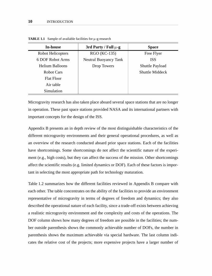
1.2 Microgravity Research Facilities
Microgravity experimental research can occur in a wide range of facilities, depending on
the fidelity, cost, and operational limitations necessary and/or available for the project.
While not necessarily exhaustive, the list presented in Table 1.1 shows a wide range of
possible facilities which can provide an environment to reproduce or simulate micrograv-
ity conditions for research purposes. The table lists 14 different environments to conduct
microgravity research in different operational conditions. The first column shows facilities
which can be housed by the individual researchers, but which don’t necessarily simulate
full 6DOF microgravity. The second column lists facilities which have full 6DOF capabil-
ities, but which are usually managed by a third party. The third column lists the existing
facilities which provide full microgravity conditions, but which present the largest devel-
opment challenges.
Figure 1.2 Discontinuity in complexity, risk, and cost at each TRL
Discontinuity in complexity,risk, and cost between TRLs.
TRL1 2 3 4 5 6 7 8 9
ComplexityRiskCost
10 INTRODUCTION
Microgravity research has also taken place aboard several space stations that are no longer
in operation. These past space stations provided NASA and its international partners with
important concepts for the design of the ISS.
Appendix B presents an in depth review of the most distinguishable characteristics of the
different microgravity environments and their general operational procedures, as well as
an overview of the research conducted aboard prior space stations. Each of the facilities
have shortcomings. Some shortcomings do not affect the scientific nature of the experi-
ment (e.g., high costs), but they can affect the success of the mission. Other shortcomings
affect the scientific results (e.g. limited dynamics or DOF). Each of these factors is impor-
tant in selecting the most appropriate path for technology maturation.
Table 1.2 summarizes how the different facilities reviewed in Appendix B compare with
each other. The table concentrates on the ability of the facilities to provide an environment
representative of microgravity in terms of degrees of freedom and dynamics; they also
described the operational nature of each facility, since a trade-off exists between achieving
a realistic microgravity environment and the complexity and costs of the operations. The
DOF column shows how many degrees of freedom are possible in the facilities; the num-
ber outside parenthesis shows the commonly achievable number of DOFs, the number in
parenthesis shows the maximum achievable via special hardware. The last column indi-
cates the relative cost of the projects; more expensive projects have a larger number of
TABLE 1.1 Sample of available facilities for µ-g research
In-house 3rd Party / Full µ-g SpaceRobot Helicopters RGO (KC-135) Free Flyer
6 DOF Robot Arms Neutral Buoyancy Tank ISSHelium Balloons Drop Towers Shuttle Payload
Robot Cars Shuttle MiddeckFlat FloorAir table
Simulation

Microgravity Research Facilities 11
dollar signs. The other columns use a scale of 1 (worst) to 5 (best) to illustrate the ability
of each facility to better serve the project. The dynamics column indicates the ability of
the facility to allow experiments to demonstrate their full dynamic effects, including
TABLE 1.2 Sample of available µ-g research facilities
Representative Environment
ExperimentOperations
Facility DO
F
Dyn
amic
s
Exp
osur
e
mic
ro-g
Dur
atio
n*
Cam
paig
nD
urat
ion*
Ope
ratio
ns
Dat
a X
fer
Acc
essi
bilit
y
Cos
t
Free Flyer 6 5 5 5(mo-y)
5(mo-y)
1 2 1 $$$$$
ISS 6 4 4 5(h-y)
5(mo-y)
2 5 3 $$$$
Shuttle Payload 6 4 4 4(h-w)
4(h-w)
2 3 2 $$$$
Shuttle Middeck 6 4 3 4(h-w)
4(h-w)
2 3 2 $$$$
RGO (KC-135) 6 3 1 2(20s)
3(1w)
3 5 4 $$$
Neutral Buoyancy Tank 6 1 1 3(h)
3(1w)
3 5 4 $$$
Drop Towers 6 4 1 1(10s)
3(1w)
3 4 4 $$$
Robot Helicopters 4(6) 2 1 2(m-h)
5(mo-y)
4 3 5 $$
6 DOF Robot Arms 6 2 1 3(h)
5(mo-y)
5 5 5 $$$
Helium Balloons 4(6) 1 1 3(h)
5(mo-y)
4 4 5 $$
Robot Cars 3(5) 1 1 3(h)
5(mo-y)
5 4 5 $
Flat Floor 3(5) 3 1 3(h)
3(1w)
4 4 5 $$
Air table 3(5) 3 1 3(m-h)
5(mo-y)
5 4 5 $
Simulation 6 2 1 5(s-y)
5(mo-y)
5 5 5 $
* Key to times: y = year, mo = month, w = week, h = hour, m = minute, s = second
12 INTRODUCTION
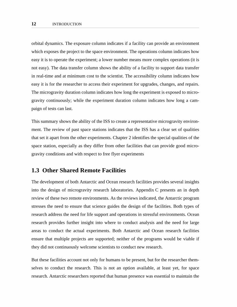
orbital dynamics. The exposure column indicates if a facility can provide an environment
which exposes the project to the space environment. The operations column indicates how
easy it is to operate the experiment; a lower number means more complex operations (it is
not easy). The data transfer column shows the ability of a facility to support data transfer
in real-time and at minimum cost to the scientist. The accessibility column indicates how
easy it is for the researcher to access their experiment for upgrades, changes, and repairs.
The microgravity duration column indicates how long the experiment is exposed to micro-
gravity continuously; while the experiment duration column indicates how long a cam-
paign of tests can last.
This summary shows the ability of the ISS to create a representative microgravity environ-
ment. The review of past space stations indicates that the ISS has a clear set of qualities
that set it apart from the other experiments. Chapter 2 identifies the special qualities of the
space station, especially as they differ from other facilities that can provide good micro-
gravity conditions and with respect to free flyer experiments
1.3 Other Shared Remote Facilities
The development of both Antarctic and Ocean research facilities provides several insights
into the design of microgravity research laboratories. Appendix C presents an in depth
review of these two remote environments. As the reviews indicated, the Antarctic program
stresses the need to ensure that science guides the design of the facilities. Both types of
research address the need for life support and operations in stressful environments. Ocean
research provides further insight into where to conduct analysis and the need for large
areas to conduct the actual experiments. Both Antarctic and Ocean research facilities
ensure that multiple projects are supported; neither of the programs would be viable if
they did not continuously welcome scientists to conduct new research.
But these facilities account not only for humans to be present, but for the researcher them-
selves to conduct the research. This is not an option available, at least yet, for space
research. Antarctic researchers reported that human presence was essential to maintain the

Thesis Roadmap 13
programs operational; emphasis was placed on the need to have staff to support research-
ers on location. Ocean research vessels are designed to host scientists on board; the capa-
bility of on-board laboratory equipment continuously grows, allowing scientists to analyze
data during the mission. Space research is constrained by the need for experiments to be
conducted by a limited set of humans, rather than the researchers themselves. The need for
this type of remote operations where the scientist is not in direct contact with the experi-
ment will be further addressed in this thesis in subsequent chapters.
1.4 Thesis Roadmap
Figure 1.3 presents the thesis overview graphically. It summarizes the content of all the
chapters and relates them with the steps of the scientific method presented at the start of
this chapter. This first chapter presents the objectives of the thesis and the motivation
behind it, as well as background research on microgravity and remote research facilities.
Chapters 2 and 3, together, present the two parts of the hypothesis presented at the start of
this chapter. Chapter 2 defines the major challenges of space research for successful tech-
nology maturation. The chapter also presents an in-depth review of the facilities available
in the ISS and the challenges faced in conducting successful scientific research. Through
this review the chapter identifies the special resources of the ISS which clearly distinguish
it from the other microgravity facilities presented in Chapter 1. These special resources
will be taken into account later on in the development of experiments.
The MIT SSL Laboratory Design Philosophy is presented in Chapter 3. The chapter first
identifies the qualities that demonstrate successful research in the specific area of dynam-
ics and control, an area of expertise for the MIT SSL. Next the chapter defines the 11 fea-
tures identified as essential for a successful research facility; these are grouped into four
main areas. The basic scientific guidelines that stand behind these groups are then pre-
sented. The chapter concludes by a review of the past MIT SSL microgravity experiments
which inspired this philosophy.

14 INTRODUCTION
Chapter 4 describes the design of the SPHERES laboratory for distributed satellite sys-
tems (DSS), which constitutes the experimental portion of the thesis. After introducing the
overall design of the hardware and operational programs, the chapter describes in further
detail how SPHERES implemented the features of the MIT SSL Laboratory Design Phi-
losophy presented in Chapter 3. Each of the four groups is presented separately.
Figure 1.3 Thesis roadmap
Chapter
Conclusions
Results
Experimentation
Hypothesis
ObjectiveMotivation
& OtherFacilities
ISS & FacilityCharacteristics
SPHERES
DesignPrinciples &Frameworks
Evaluations
Conclusions
1
2
3
4
5
6
Objectives and method. Review of other micro-gravityresearch facilities and other remote research facilities.Overview of the NRC recommendation.
Study on the types of research conducted aboard the ISSand its special resources.
The design of SPHERES as related to the MIT SSLLaboratory Design Philosophy and the use of the ISS.
The design principles which generalize the philosophyfor space technology maturation aboard the ISS; a designframework and an evaluation framework for applicationof the principles.
The design and evaluation frameworks applied toSPHERES.
Summary of the thesis, contributions, and future work.7
SSL DesignPhilosophy
The MIT SSL Laboratory Design Philosophy for thedesign of projects that will host dynamics and controlsexperiments.

Thesis Roadmap 15
Chapter 5 presents the seven design principles that resulted from implementing SPHERES
to a) follow the MIT SSL Laboratory Design Philosophy and b) to operate in the ISS. This
chapter presents each of the principles in a separate section, explaining the derivation of
the principles from the experimentation with SPHERES, and then describing the principle
itself. Two application frameworks are presented in Chapter 5: a design framework to aide
investigators in the creation of experiments that best utilize the resources of the ISS and an
evaluation framework to determine if a project uses the ISS appropriately. These frame-
works can be utilized as part of an "institutional arrangement" for conducting science on
the ISS. Chapter 6 thoroughly analyses the SPHERES facility using both frameworks.
Chapter 7 concludes the thesis by summarizing how the design principles and frameworks
fulfill the objectives of the thesis.

16 INTRODUCTION

Chapter 2
MICROGRAVITY RESEARCH ABOARD THE ISS
This chapter expands on the first part of the hypothesis presented in Figure 1.1: the use of
the International Space Station as a host creates the perfect low-cost environment for tech-
nology maturation. The chapter discusses the challenges of µ-g research identified from
the literature search and through past experiences of the MIT SSL. Literature about the
ISS, including a review of research up to date, helps identify the type of experiments con-
ducted in the ISS; this chapter specifies what the thesis regards as a technology maturation
experiment, as related to current research conducted aboard the ISS. Lastly, the chapter
presents the special resources offered by the ISS.
2.1 Issues and Challenges of Microgravity Research
The literature review of Chapter 1 provides insight into the issues and challenges faced by
microgravity research. Achieving maturation of space technologies was tied by the Tech-
nology Readiness Levels to the ability to operate in representative environments. The
TRLs and availability of these environments define the challenges of micro gravity
research. TRLs were introduced in Chapter 1 as a proposed method to mature technology
in a step-wise manner. As shown in Figure 1.2 on page 9, three primary drivers have
impact on the ability of a technology to follow all TRLs: risk, complexity, and cost. The
review of other facilities indicated that remote operations also pose a challenge to space
technology maturation. Lastly, it is shown by the fact that previous space stations pro-
17

18 MICROGRAVITY RESEARCH ABOARD THE ISS
grams were driven in many ways by political and social needs, and that the high visibility
of these programs is an issue which cannot be ignored.
Risk. Risk exists in every stage of space technology maturation, from the feasibility of
the program itself to the actual operation of equipment. Risks are created by the environ-
ment, costs, and politics which surround microgravity research. The space environment
creates risks not experienced inside the earth atmosphere, such as space radiation and col-
lision with natural objects. The inability of humans (in most cases) to work directly with
deployed spacecraft of the projects can result in the permanent reduction of capabilities
unless full redundancy is implemented. When humans can access the spacecraft, the avail-
ability of resources (including time, equipment, and parts) to repair spacecraft is limited.
Costs, while an important factor on their own, also contribute to the risk of a space mis-
sion; the costs drive the development time down and limit the ability to create fully redun-
dant systems. Politics also adds to the risks of a mission, although in a different manner.
Due to politics, space engineering tends to work in a conservative fashion, many times uti-
lizing old-but-trusted technologies, rather than the latest technologies, for common parts
of a space craft; these older technologies usually work behind highly advanced science
items. Creating interfaces between the technologies puts a risk the feasibility of the mis-
sion and can potentially limit the usefulness of the new advanced technologies to be
tested. When only advanced technologies exist, the risk of using them is too high for the
political drivers behind the project. Politics can also reduce the time for development, cre-
ating new risks due to unforeseen problems. Reducing the risk of a mission by allowing
humans to operate new technologies in a controlled environment is a goal for the use of
the ISS.
Complexity. Space systems are some of the most complex systems created by human
kind. Spacecraft interface dozens of sub-systems, contain up to miles of cable, which carry
thousands of electronic signals, utilize advanced science items, and operate using a num-
ber of different robust real-time software implementations. While a specific tool for a
spacecraft can be tested on its own in simple manners during preliminary tests, as that tool

Issues and Challenges of Microgravity Research 19
is integrated into the rest of the spacecraft, the complexity of its operations grow. That is,
as a technology matures towards a high TRL, the complexity of using the tool grows.
Increased complexity usually results in higher costs and the need for more personnel to
work on the development of the technology. The increased complexity also adds to the
risk, as the addition of interfaces creates new possible failure points. Therefore, it is desir-
able to lower the complexity of a mission and/or to mature individual sub-systems as far
as possible prior to integration into the more complex spacecraft. Further, it is desirable to
test the integration of sub-systems in an environment which does not necessarily add as
much complexity as developing the space-qualified product.
Cost. For many space programs, cost becomes the deciding factor in the future of the
mission. Space missions have costs higher than most other research on the ground due to
the need for expensive specialized equipment, launch vehicles, and operational costs. The
other issues presented also create an increase in cost, for example: reducing risk by redun-
dancy increases cost; increased complexity increases cost; the drivers behind politics are
mostly economic. The high cost of these missions creates inbalance in the funding of the
science programs for ground-based research and space-based research; this forces space-
based research to be highly beneficial to the funding sources, something adding extra bur-
den to the researchers beyond the direct science goals of a mission. Therefore, to over-
come the issue of cost for space research one must first, allow multiple researchers to
benefit from the research, ensuring that the research benefits a large portion of the popula-
tion; and second, that the other factors which affect the cost of a mission are reduced in
such a way that the ultimate cost of the mission is also reduced.
Remote Operations. The need for remote operation means that the scientists will not be
present in the actual tests; rather an astronaut is trained to operate the facility. While astro-
nauts are highly-educated members of the space community, they are rarely experts on all
the experiment fields to which they are assigned. Yet, in some cases astronauts will have
to make decisions based on real time results; these decision potentially affect the success
of the research. In these cases astronauts will require substantial training to be able to

20 MICROGRAVITY RESEARCH ABOARD THE ISS
make the best decisions; at the same time the experimental facility will need to provide
astronauts real-time feedback information for them to make the necessary decisions. In
other cases astronauts may not need to do any decision making, but in that case a
researcher must create an automated experiment and/or create the necessary data links to
make the decisions on the ground and command the space-based experiment remotely. A
researcher needs to balance the need of astronauts to make real-time decisions as com-
pared to the complexity needed to automate the equipment.
Visibility. The visibility of space missions is usually on the extremes: the major missions
are highly visible and subject to substantial public review while smaller missions go unno-
ticed, very few are in the middle ground. This presents a challenge to the researcher.
Highly visible missions will face extreme safety and public relations pressure. This tends
to increase the cost of the mission as the safety requirements increase. Public relations
pressure tends to affect the timeline of the mission, sometimes forcing steps to be skipped;
at the same time, public relations tend to criticize high costs, forcing the mission to bal-
ance the cost to achieve the necessary safety with the cost to achieve the scientific goals
(sometimes causing cuts in the goals of the mission). In a similar fashion, a high-visibility
mission calls for the use of advanced technologies to attract the attention of the public; but
the safety concerns drive towards the use of conservative technologies in other parts of the
project. On the other hand, a low-visibility mission will face hard times to obtain the nec-
essary funding and attention to be successful. Even if the necessary funding is obtained,
low visibility of a mission may cause its facilities and results to not be used effectively,
making the mission short-lived.
The use of the International Space Station should address these issues and challenges.
Ultimately we wish to answer:
• Can the use of the ISS reduce the risk of space technology maturation?
• Is the complexity of a project that goes through the ISS reduced?
• Can the cost of a project be reduced by using the ISS?
• Are the remote operations of the ISS effective?

Research Areas of the International Space Station 21
• Can the use of the ISS remove the visibility factor from the feasibility of amission?
2.2 Research Areas of the International Space Station
To answer whether the ISS can address the issues and challenges of space research one
must first understand what the ISS is. Appendix D presents a detail review of the
resources available aboard the ISS and the current challenges and future upgrades of the
program. This section concentrates on the objectives of the ISS program, creating a direct
relationship with the success of past space stations, and helping identify the research con-
ducted aboard the ISS which directly relates to the results of this thesis.
The objectives of the ISS as stated in the ISS Familiarization Manual developed by NASA
are:
"The purpose of the ISS is to provide an “Earth orbiting facility that housesexperiment payloads, distributes resource utilities, and supports permanenthuman habitation for conducting research and science experiments in amicrogravity environment.” (ISSA IDR no. 1, Reference Guide, March 29,1995)
"This overall purpose leads directly into the following specific objectivesof the ISS program:• Develop a world-class orbiting laboratory for conducting high-value sci-
entific research• Provide access to microgravity resources as early as possible in the
assembly sequence• Develop ability to live and work in space for extended periods• Develop effective international cooperation• Provide a testbed for developing 21st Century technology." [NASA, 1998]
After creating these objectives, NASA worked to further detail the research objectives of
the ISS. To this purpose, NASA has created an ongoing program to determine the
"research directions" of the ISS. During the development of these directions, NASA first
defined the ISS as a special type of laboratory, one which has three special purposes:
• "an advanced testbed for technology and human exploration;

22 MICROGRAVITY RESEARCH ABOARD THE ISS
• a world-class research facility; and
• a commercial platform for space research and development." [NASA, 2000]
As of January 2000 the NASA Office of Life and Microgravity Science Applications had
identified a number of research fields which can directly use the resources provided by the
ISS to advanced human knowledge and provide benefits to the people in the ground; these
are presented in Appendix D.
The objectives and research directions of the ISS address some of the challenges identified
in the first section of this chapter by creating a facility which will benefit a large number
of scientists; ultimately the science obtained will benefit a large portion of Earths popula-
tion once NASA’s science objectives are met.
2.2.1 Thesis Research Area Identification
The ISS creates a special environment in space for conducting a wide range of micrograv-
ity experiments. This section studies the types of experiments conducted aboard the ISS
and defines the type of experiments that this thesis concentrates on.
NASA conducts multiple research experiments in the ISS simultaneously. Each “expedi-
tion” of the ISS – each crew rotation – is given a delimited set of tasks, which are pub-
lished by NASA. Table 2.1 shows the experiments that Expedition 6 conducted through
their six month rotation. This expedition was chosen as a sample since it constituted a six
month period when the ISS operated normally with three crew members and standard sup-
ply missions.
Research of the goals behind each of the twenty experiments that took place on Expedition
Six allows division of the experiments into the following main areas:
• Experiment Operation Types
- Observation
- Exposure
- Iterative Experiments

Research Areas of the International Space Station 23
• Major areas of study
- Educational
- Pure Science
- Technology
TABLE 2.1 Research experiments of Expedition 6
Id NASA Field Experiment Area Type
1 Bioastronautics Research
The Effects of EVA on Long-term Exposure to Microgravity on Pulmonary Function (PuFF)
Science Iterative
2 Renal Stone Risk During Space Flight: Assessment and Coun-termeasure Validation (Renal Stone)
Science Exposure
3 Study of Radiation Doses Experienced by Astronauts in EVA (EVARM)
Science Exposure
4 Subregional Assessment of Bone Loss in the Axial Skeleton in Long-term Space Flight (Subregional Bone)
Science Exposure
5 Effect of Prolonged Spaceflight on Human Skeletal Muscle (Biopsy)
Science Exposure
6 Promoting Sensorimotor Response Generalizability: A Coun-termeasure to Mitigate Locomotor Dysfunction After Long-duration Space Flight (Mobility)
Science Exposure
7 Spaceflight-induced Reactivation of Latent Epstein-Barr Virus (Epstein-Barr)
Science Exposure
8 "Monitoring of Heart Rate and Blood Pressure During Entry, Landing, and Egress: An Index of Countermeasure Efficacy (Entry Monitoring)"
Science Exposure
9 Chromosomal Aberrations in Blood Lymphocytes of Astro-nauts (Chromosome)
Science Exposure
10 Foot/Ground Reaction Forces During Space Flight (Foot) Science Iterative?
11 Physical Sciences Protein Crystal Growth—Single-locker Thermal Enclosure Sys-tem (PCG-STES)
Science Iterative
12 Microgravity Acceleration Measurement System (MAMS) Technology Exposure
13 Space Acceleration Measurement System II (SAMS-II) Technology Exposure
14 Investigating the Structure of Paramagnetic Aggregates from Colloidal Emulsions for the Microgravity Sciences Glovebox (MSG-InSPACE)
Science Iterative
15 Vibration Isolation System for the Microgravity Sciences Glovebox (MSG-g-LIMIT)
n/a n/a
16 Coarsening in Solid-Liquid Mixtures for the Microgravity Sci-ence Glovebox (MSG-CSLM)
Science/Tech Iterative
17 Space Product Development
Zeolite Crystal Growth Furnace (ZCG) Science/Tech Iterative
18 Microencapsulation Electrostatic Processing System (MEPS) Science Iterative
19 Space Flight Crew Earth Observations (CEO) Education Observation
20 Earth Knowledge Acquired by Middle-School Students (Earth-KAM)
Education Observation
21 Materials International Space Station Experiment (MISSE) Science Exposure

24 MICROGRAVITY RESEARCH ABOARD THE ISS
Experiment Operation Types
Observation. Experiments that consist solely of the observation of celestial bodies
(either the Earth or others), are considered observation experiments. For example, when
astronauts are asked to take pictures of Earth, without conducting any further research on
the results.
Exposure Experiments. Exposure experiments are those that utilize the µ-gravity envi-
ronment of the ISS solely to expose material to the reduced gravity and/or space environ-
ment, without actively conducting experiments in the ISS with the materials or subject
being tested. These experiments include, for example, medical experiments where astro-
naut biological data are measured before and after the flight, but no science is performed
during the expedition – possibly the astronauts may conduct special exercises during the
expedition, but since no measurements or other science is conducted during the expedition
itself, these are considered exposure times, not research times.
Iterative Experiments. The other main type of operations for ISS experiments are those
that require multiple iterations of test runs while the experiments are aboard the space sta-
tion. This definition does not preclude the type or location of the experiments, but rather
identifies their operational nature. An experiment may be performed either inside our out-
side the station, and it may be for pure science or tests of new technologies. The most
important concept for this type of operation is that the facilities must be able to present
results and perform new experiments during their time in the ISS.
Experiment Areas
Educational. The ISS is often used to conduct activities with an educational goal. The
ISS crew continuously communicates with students on Earth, via both audio and video;
they take pictures to be used in educational exercises, and even sometimes conduct simple
experiments developed by children. This research time is outside the scope of this thesis,
since the goal is not directed towards the development or understanding of new technolo-
gies.

Research Areas of the International Space Station 25
Pure Science Experiments. A large portion of experiments aboard the ISS are conducted
to learn more about the pure sciences. These experiments use µ-g to understand how
things behave differently between gravity and micro- gravity conditions. They also help
create materials in new ways that are not possible on Earth. Ultimately these experiments
provide results for use in ground products. In some cases, the experiments utilize many of
the ISS resources to conduct iterations of the full research cycle, where results are
obtained aboard the ISS and new experiments started with knowledge obtained from those
initial results. In other cases pure science experiments consist solely of observation or
exposure.
Space Technology Experiments. These experiments are those that test new technologies
for use in future space missions. These technologies allow better understanding of the µ-g
environment to facilitate the access and use of space. While pure science experiments
study the effects of the space environment on biological or physical items, space technol-
ogy experiments demonstrate the ability of human created items to operate correctly in a
microgravity environment. The experiments aboard the ISS allow the necessary technol-
ogy demonstration in a relevant space environment to advance the technology through
several TRLs (the definition of a relevant environment is presented in Appendix A).
Thesis Concentration
This thesis concentrates on iterative experiments that serve science and technology goals.
Emphasis will be on those experiments related to space technology, but some science
experiments can serve as an important example of how the ISS enables research in space
to advance an area by allowing iterations. The thesis does not dive into experiments that
are solely for observation or exposure, other than to identify the division of time spent in
the ISS between these types of experiments and to evaluate the subsequent effectiveness
of the use of the ISS.

26 MICROGRAVITY RESEARCH ABOARD THE ISS
2.3 Special Resources of the ISS
This chapter begins with the introduction of the major challenges and issues of micrograv-
ity research identified through literature research: risk, complexity, cost, remote opera-
tions, and visibility. The goal of the chapter is to identify whether the ISS can help reduce
the negative effect of these issues on space technology maturation. The chapter presents
an overview of the ISS objectives and identifies the challenges of the ISS itself. This study
of the ISS leads to the identification of several special resources of the station which do in
fact help it reduce the effects of the identified challenges, and which contribute to the cor-
rect utilization of the ISS as a laboratory for space technology maturation. The following
resources have been identified as most important:
Crew. The fact that humans are present in the space station to interact with and control
different facilities is the most obvious and yet many times overlooked resource available
in the ISS. While all reviewed reports identified crew availability as a major challenge for
the ISS, clearly indicating the need to maximize their time dedicated to research, many
times scientists put heavy emphasis on automation and independence from the crew. Yet,
the crew can help reduce the effects of many challenges: risk is reduced since humans can
stop an experiment which is operating incorrectly; complexity and cost can be reduced by
the need to remove automation tools. Therefore, any project that uses the ISS should
actively use the humans to help the science and reduce risk, complexity, and cost. The ulti-
mate goal is to determine the correct balance between astronaut availability and need.
Communications. The issue of communications and data download resonated through
all the reviews of the ISS. Correct use of the ISS communications system, and its constant
expansion, is clearly a priority for NASA and a special resource which benefits all users of
the ISS. The availability of continuous high-bandwidth communication to ground reduces
the cost and complexity of missions which would otherwise need their own communica-
tions equipment. The availability of ever-increasing communications features will help
with the issue of remote operation as real-time video and other teleconferencing options

Special Resources of the ISS 27
become increasingly available. Therefore, scientists should utilize the ISS as a direct com-
munications link between them and their experiments.
Long-term experimentation. A unique features of the ISS is that it allows long-term
microgravity experimentation in a laboratory environment. The long-term nature of the
ISS helps to reduce the effects of high visibility as space research becomes part of daily
life at NASA and the scientific community. The ISS allows space technology advances to
come over longer periods of time, where specific one-time events (such as a landing or a
docking) no longer need to mark the success or failure of a mission. Instead, the long-term
nature of the ISS allows technology to mature over small steps in a low-visibility environ-
ment, allowing scientists to better concentrate on their research rather than outside factors.
At the same time experiments which reach the space station will always have high visibil-
ity among the scientific community. Further, once they demonstrate revolutionary
advances, new technologies will gain high-visibility among the public in general.
Power sources. The ISS can provide several kilowatts of power to each experiment.
Because power is usually a trade-off between mass (i.e., larger batteries provide more
power but have larger mass), utilizing the existing power sources of the ISS can help to
substantially reduce the mass of an experiment, and in turn its cost. Because power
sources are a constant safety concern, removal of power sources from an experiment also
reduces the risk of the mission. Therefore, ISS supplied power should be utilized by the
experiments, otherwise experiments that send their own power sources are duplicating an
existing resource and wasting up-mass to the ISS.
Atmosphere. While some times an experiment intends to demonstrate the ability of its
hardware to operate in a space environment, the development of ‘rad-hard’ techniques has
been understood for several decades. Instead, many experiments wish to demonstrate the
ability of their hardware and software to perform correctly in a microgravity environment
without the need to worry about hardware failures. In these cases the pressurized environ-
ment of the ISS not only provides safety for humans, but also for electronics and struc-

28 MICROGRAVITY RESEARCH ABOARD THE ISS
tures. Experiments that can be performed inside the station can have a substantial
reduction in cost, complexity, and risk, as compared to free-flyers in space, since they no
longer need to worry about being exposed to the space environment radiation and vacuum.
Cost is reduced directly by the use of standard components; complexity is reduced since
protection equipment is no longer necessary; risk is reduced since the experiment is no
longer exposed to the harsh conditions of space and therefore the probability of failure is
lowered.
Table 2.2 summarizes the special resources of the ISS and their effects on the challenges
of microgravity research. The next chapter will present the MIT SSL Laboratory Design
Philosophy, which also addresses those challenges, but from the perspective of creating a
new experiment which not only uses existing resources but also creates new features to
build upon the existing resources.
TABLE 2.2 Special resources of the ISS that facilitate microgravity research
Resource Ris
k
Com
plex
ity
Cos
t
Rem
ote
Ope
ratio
ns
Vis
ibili
ty
Crew ↓ ↓ ↓Communications ↓ ↓Long-term experimentation ↓Power Sources ↓ ↓ ↓Atmosphere ↓ ↓ ↓
↓ = reduces challenge

Chapter 3
THE MIT SSL LABORATORY DESIGN PHILOSOPHY
This section presents the second part of the hypothesis presented in Figure 1.1: the MIT
SSL Laboratory Design Philosophy can serve as a set of guidelines for the successful
development of microgravity research experiments. These guidelines were created from
the experience of designing, building, and operating multiple µ-g testbeds, and were the
guidelines that drove the design of the SPHERES testbed.
This chapter contains three main parts. The first part discusses the characteristics of a
space technology which must be demonstrated to prove technology maturation, as related
to the fields of dynamics and controls. Next, the chapter presents the experiments con-
ducted by the MIT SSL which allowed the demonstration of those characteristics. The
development of these experiments led to the identification of features required of a testing
environment to allow the demonstration of the technologies. That is, the demonstration
must show the technology posses the characteristics to prove its maturation without being
limited by the testing environment. These features are grouped into four common areas;
each of these four areas is explained based on scientific research practices. These features
form the MIT SSL Laboratory Design Philosophy.
3.1 Definitions
Before presenting the MIT SSL micro gravity projects and the Laboratory Design Philos-
ophy which resulted from them, it is important to understand two concepts that will appear
29

30 THE MIT SSL LABORATORY DESIGN PHILOSOPHY
continuously throughout the remainder of this thesis. The Laboratory Design Philosophy
contains one key word: laboratory. The term laboratory is used not only to represent the
physical research where research is conducted. From the dictionary (Merriam-Webster)
definition of a laboratory we can obtain further insight:
Main Entry: lab·o·ra·to·ry
1 a : a place equipped for experimental study in a science or for testing andanalysis; broadly : a place providing opportunity for experimentation,observation, or practice in a field of study b : a place like a laboratory fortesting, experimentation, or practice <the laboratory of the mind>
The meaning of the word laboratory in the design philosophy, and for the remainder of the
thesis, specifically addresses the need to support experimentation in a field of study. The
support is provided not only by physical equipment, but also by the correct organizational
structure to ensure that a field of study can be researched.
The physical equipment which forms part of a laboratory is the facility. A facility is
defined (Merriam-Webster) as:
Main Entry: fa·cil·i·ty
1 : the quality of being easily performed
2 : ease in performance : APTITUDE
3 : readiness of compliance
4 a : something that makes an action, operation, or course of conduct easier-- usually used in plural <facilities for study> b : something (as a hospital)that is built, installed, or established to serve a particular purpose
This thesis follows the definition that a facility makes […] a course of conduct easier and
is established to serve a particular purpose. In the case of this thesis, a facility serves to
facilitate research in the field of study for which a laboratory is established.
Therefore, a reference to a facility indicates the presence of hardware equipment to make
conducting research easier. The use of the word laboratory means that a full research pro-
gram has been created to enable research on a field of study.

Characteristics of a Mature Technology Demonstration 31
3.2 Characteristics of a Mature Technology Demonstration
The MIT SSL concentrates its research on dynamics and controls technologies. Therefore,
the experiments developed at the MIT SSL test a wide range of metrology and control
algorithms, as well as sensor and actuator technologies which enable the algorithms to
succeed. This section presents the characteristics which must be exhibited by a dynamics
and control technology to demonstrate it has matured. These characteristics form the basis
behind the objectives of the different dynamics and controls experiments; while the goals
of each specific mission are unique, the goal is that the mission-specific algorithms all
exhibit the characteristics presented in this section. While these are related directly to the
topics of dynamics and control studied at the MIT SSL, their application can be expanded
to more general demonstrations in most cases.
These characteristics can also be related to the Technology Readiness Levels. The NASA
TRLs provide high-level guidelines of when a technology matures for operation at differ-
ent steps in its reach for space operation. These characteristics go one level down, they are
those properties of a dynamics and control test that must be met every time to demonstrate
that a specific TRL level has been met. To demonstrate fulfillment at a specific level, the
technology must exhibit the following characteristics:
Demonstration and Validation. For a technology to mature, it must be demonstrated in
the correct environment, with results clearly showing the accomplishments of the technol-
ogy. Results observed in a physical system must be validated with data obtained during
the successful completion of the demonstration.
Repeatability and Reliability. The results of a mature technology must be repeatable,
that is, they must happen more than once under similar operating conditions. Further, pos-
itive results must be obtained in the presence of the different disturbances and commands
that may be present during a mission to demonstrate the reliability of the algorithms.
32 THE MIT SSL LABORATORY DESIGN PHILOSOPHY
Determination of Simulation Accuracy. A successful technology demonstration must
help validate simulations and other tests of lower fidelity. The results of control experi-
ments in a space research laboratory can be compared with simulations to provide confi-
dence in simulation techniques and to gauge the simulation accuracy.
Identification of Performance Limitations. In order to determine the success of new
technologies or algorithms one must push these to their limits. Mature technologies must
provide insight into most of the physical constraints of a system that may not be observ-
able in a simulation or ground test.
Operational Drivers. Systems issues such as sensor-actuator resolution, saturation, non-
linearity, power consumption, roll-off dynamics, degradation, drift, and mounting tech-
niques are most often constraints rather than design variables; that is, these quantities can-
not be easily changed by the scientist, but rather scientists must design their experiment
around them. Hardware experiments allow scientists to learn the quantitative values of
these constraints, which are important during the creation of system models used in the
design of control and autonomy algorithms. A mature technology operates successfully in
the presence of these drivers.
Identification of New Physical Phenomena. New physical phenomena are usually dis-
covered through observation of physical systems. A mature technology demonstration
allows for the identification of these phenomena, creation of models for them, and the
exploitation of this new knowledge in future investigations.
The MIT SSL has conducted microgravity experiments over the past two decades to dem-
onstrate and validate dynamics and control technologies. While these experiments covered
different areas of research (non-linear dynamics, fluid slosh, load sensors, robust control),
each of them attempted to demonstrate each of these characteristics in the technology they
tested. The following section summarizes the experiments.

MIT SSL Previous Space Experiments 33
3.3 MIT SSL Previous Space Experiments
The MIT SSL has designed, built, and operated a multitude of flight experiments in the
past. The lessons learned from these experiments led to the development of the sets of
demonstration characteristics and test environment features. The experiments include:
• Mid-deck 0-g Dynamics Experiment (MODE), which flew on STS-48 inSeptember 1991 and its re-flight on STS-62 in March 1994.
• Dynamic Load Sensors (DLS), which flew on MIR for about three years.
• Middeck Active Control Experiment (MACE), which flew on STS-67 inMarch 1995.
• MACE Re-flight, which was the first crew-interactive space technologyexperiment conducted aboard the ISS by Expedition 1 in December 2000.
Appendix E reviews the research conducted through the three programs (MODE, DLS,
and MACE) and further discusses the identification of the common features that enabled
these experiments to advance dynamics and control algorithms for space technologies.
Table 3.1 presents a summary of past MIT SSL microgravity experiments. The table sum-
marizes the mission and its areas of study.The table also shows the total cost of the mis-
sion and the time to flight. Re-flight opportunities clearly lowered both metrics. The
MODE experiment characterized itself by the creation of the generic equipment (the
ESM), which allowed future missions, including DLS, to be developed with low cost and
in a small time-frame. DLS further enhanced the success of MODE by operating over an
extended period of time. The MACE program developed its own set of generic equipment,
which was used over two flights. The MACE re-flight made substantial use of the original
MACE hardware to lower its cost and time to flight. Further, MACE allowed algorithms
to be selected and modified during the mission, allowing a larger number of areas of study
to be investigated.
MODE, DLS, and MACE tested a number of different space technologies to aid in the
development of new algorithms and sensors for dynamics and control. Each of these
experiments exhibited special features which helped to mature the technologies in a cost
effective manner by utilizing the available environments to their full extent. The identifi-

34 THE MIT SSL LABORATORY DESIGN PHILOSOPHY
cation of these features led to the development of the MIT SSL Laboratory Design Philos-
ophy which helps guide the design of new experiments. These features are presented
below.
3.4 Features of a Laboratory for Space Technology Maturation
In the area of dynamics and control different technology validation tools play different
roles in the maturation process. Simulations, while versatile, low cost, and low risk, only
address issues that the control engineer remembers to consider. Implementation on hard-
ware forces the engineer to pay attention to not only the technology but also the details of
its implementation. It is these details which a hardware testing facility must allow to be
identified correctly.
A testing facility designed to mature technologies must ensure that the tests meet the char-
acteristics presented above in such a way that the technology, rather than the facility itself,
limits the ability to demonstrate the maturation of the technology. The facility must create
the necessary environment for successful demonstration, so that the results are relevant to
TABLE 3.1 Summary of MIT SSL microgravity experiments
Experiment HostDate(year) Areas of Study Cost
Time-to-flight*(years)
On-orbit time
(weeks)MODE STS-48 91 Microgravity fluid and
structural dynamics$2M 3 1
MODEReflight
STS-62 94 Non-linear structural dynamics on truss
structures
$1M 2 1.7
DLS MIR 96-97 Crew induced dynamic disturbances
$0.75M 1 40
MACE STS-67 95 Advanced control design on non-linear
structures
$4M 3 2
MACEReflight
ISS(Exp 1)
00-01 Neural networks, non-linear characterization, reaction wheel isolation
$1M 1.5 36
* Time to flight = contract start to actual flight

Features of a Laboratory for Space Technology Maturation 35
the operational environment of the technology. The performance limitations of the facility
must not limit the technology; it is the only way to ensure that the results of the tests are
bound by the technology being tested. Further, to create a laboratory environment, the
facility must allow the demonstration of all the areas of study which comprise a technol-
ogy, allowing multiple scientists to conduct experiments over long periods of time. Over-
all, the laboratory must facilitate reaching technology maturation. Therefore, a laboratory
must meet a minimum set of requirements that will surpass the capabilities of the technol-
ogy.
Each of the MIT SSL microgravity experiments presented above satisfied one or more of
these requirements. The features of these facilities which enable them to meet these have
been identified and brought together into the MIT SSL Laboratory Design Philosophy.
These features will drive the lower-level design of new testbeds, after a high-level design
has been decided upon based on the project goals and TRLs to be met. The identified fea-
tures of microgravity laboratories are:
Data Collection and Validation. A successful research environment must provide data
collection of accuracy and precision scalable to the final system to demonstrate operation
of the new algorithms or technologies. The collected data needs to ensure the technology
is fully observable. The feedback from the research environment must be precise enough
to validate the operation of the new technology. The facility must also ensure that the data
is presented in a manner useful to demonstrate the validity of the results. Further, the data
must be independently validated by a truth sensor.
Repeatability and Reliability. To demonstrate the repeatability of a new technologies,
the research laboratory environment must have a better repeatability and reliability rate
than the technologies to be tested. The environment must be able to provide similar test
conditions through an extended period of time. Similarly, to demonstrate the reliability of
a new controller, the environment should be easily changed so as to create different distur-
bances and commands. Therefore, the research environment must be a controlled setup,

36 THE MIT SSL LABORATORY DESIGN PHILOSOPHY
where interaction with the facility can easily recreate an environment or change it in a
controlled manner.
Physical End-to-End Simulation. The test environment must provide a sufficiently real-
istic simulation of the expected operational environment and performance metrics. The
environment must correctly simulate the hardware required for the actual mission, includ-
ing the use of representative sensors, actuators, electronics, and other active hardware.
Further, to fully capture the dynamics of the mission, the physical end-to-end simulation
must allow its dynamics to be fully understood such that the results can be applied to the
actual mission which may have different dynamics. Otherwise, important couplings and
perturbations may be masked and the ability to achieve requisite performance levels is dif-
ficult to ascertain. The hardware simulation must also allow all essential operational steps
of the mission to occur, either continuously or step-wise, so that all parts of the technology
can be demonstrated.
Generic versus Specific Equipment. All laboratories distinguish between that which is
being tested and the facilities needed to conduct those tests. Since it is difficult to modify
hardware in the space environment, it is desired that laboratories based in the ISS have a
set of generic equipment able to provide basic operation of the laboratory. Test-specific
equipment can be attached to the generic equipment to better model a specific mission. In
this way the laboratory can accommodate a multitude of research projects. This re-usabil-
ity improves the cost-effectiveness of the research.
Hardware Reconfiguration. To demonstrate the reliability of a new algorithm or tech-
nology, it is desirable to manipulate the hardware configuration during a specific test to
demonstrate increasingly complex geometry or components. Therefore, both the generic
and specific hardware should allow easy reconfiguration.
Supporting Extended Investigations. The effectiveness of experimental research is
generally correlated with the number of iterative research cycles completed. Sometimes, a
test can reveal totally unexpected behavior. Under these circumstances, a cycle cannot

Features of a Laboratory for Space Technology Maturation 37
closely follow the previous cycle since time needs to be spent re-exploring the theory
before the original hypothesis can be appropriately refined. Therefore, there is a need to
maintain access to the laboratory under repeatable test conditions following an extended
period of no tests.
Risk Tolerant Environment. Laboratory tests are often conducted on immature and
unproven technology. The environment must be designed to accommodate failure or
unexpected behavior (e.g., control system instability). Such occurrences must not pose
harm to the researcher, the test article or the test equipment. Furthermore, the researcher
must expect such occurrences, otherwise they are not pushing the edge of knowledge and
capability.
Software Reconfiguration. The ability to alter software provides much more versatility
in manipulating test conditions. In particular, when the technology being tested is mani-
fested as software (e.g., control, metrology, system identification, and autonomy algo-
rithms), the ease with which that software can be altered directly impacts the productivity
of the tests.
Human Observability and Manipulation. Research is a very human-in-the-loop pro-
cess. The researcher's ability to observe behavior, refine a hypothesis, manipulate the test
conditions, and observe new behavior is at the core of the iterative experimental research
process.
Facilitating Iterative Research Process. While human interaction and laboratory recon-
figurability are prerequisites for a laboratory, they alone are not sufficient to facilitate the
iterative research process. The cycle time from posing an hypothesis to refining that
hypothesis based upon correlation between experiment and theory must be sufficiently
brief. This helps the researcher track the evolution of inquiry and offers the opportunity to
explore alternatives more fully. Laboratory interfaces must be defined to minimize the
resources consumed by each research cycle.
38 THE MIT SSL LABORATORY DESIGN PHILOSOPHY
Supporting Multiple Investigators. Shared access to a research laboratory dramatically
improves cost-effectiveness. Therefore, reconfigurability of the testbed should allow mul-
tiple investigators to participate in the program. Guest investigators must not only have
access, but that access must be supported by the principal investigator, since the guest
investigators may not be familiar with, or able to be present in, the laboratory environ-
ment.
3.4.1 Interactions Between the Features
The presented features of a laboratory are not independent of each other. A single charac-
teristic of a system can help achieve multiple features, and success in some features helps
to achieve success in others. Table 3.2 presents the interactions between the different fea-
tures. The table shows when a feature in the rows helps a feature in columns; when an
interaction between a feature in the rows exists with one in the columns, a check mark
indicates this relationship. This section explains the interactions that occur as each feature
in a row helps one or more of the other features.
Data Collection and Validation. The iterative research process depends on data analy-
sis between iterations, therefore good data collection and validation is necessary. If the
data quality is not precise enough, then the simulation will not achieve full physical end-
to-end simulation of the experiment.
Repeatability and Reliability. The iterative research process depends on multiple itera-
tions being carried out at different periods in time, with the guarantee that the test condi-
tions will be similar. Otherwise, subsequent tests may waste resources trying to identify
what has changed about the test environment. To support extended investigations the hard-
ware must perform the same way over long periods of time, which cannot be done without
a repeatable system. When a facility is known to be reliable scientists have greater confi-
dence to push the limits of their technology towards the limits of the facility, aiding in cre-
ating a risk-tolerant environment.

Features of a Laboratory for Space Technology Maturation 39
Human Observability and Manipulation. Humans help the iterative research process
by reducing the time to get feedback (data download and comments on observed behavior)
on experiment runs. Humans aid extended investigations by enabling simple ways to re-
supply consumables and store hardware in between experiments. Humans provide for a
risk tolerant environment in two ways: first, strict safety requirements reduce the risk of
catastrophic failures; second, humans can intervene in the case of failures that would oth-
erwise damage the facilities. Humans help support both hardware reconfiguration capa-
bilities and multiple investigators by simplifying the methods to change the hardware and,
in doing so, allowing the hardware to operate in different modes for different scientists.
Physical End-to-end Simulation. The participation of multiple scientists in a project
usually implies that they are working on several areas of a technology. A system which
achieves physical end-to-end simulation will provide better results for multiple scientists
TABLE 3.2 Interaction between the SSL Design Philosophy elements
These features ↓ support these features→
Dat
a C
olle
ctio
n
Rep
eat.
/ Rel
iab.
Itera
tive
Proc
ess
Hum
an O
bs./M
an.
End-
to-E
nd
Exte
nded
Inve
st.
Ris
k To
lera
nt
Gen
eric
/Spe
cific
HW
reco
nfig
.
SW re
conf
ig
Mul
tiple
Inve
st.
Data Collection and Validation
Repeatability and Reliability
Facilitating Iterative Research Process
Human Observability and Manipulation
Physical End-to-End Simulation
Supporting Extended Investigations
Risk Tolerant Environment
Generic versus Specific Equipment
Hardware Reconfiguration
Software Reconfiguration
Supporting Multiple Investigators
40 THE MIT SSL LABORATORY DESIGN PHILOSOPHY
working on different areas of a technology, since the system behavior will be valid for all
of them.
Supporting Extended Investigations. The iterative research process depends on the
availability of sufficient time and data for scientists to analyze results and make modifica-
tions to their initial hypothesis. Operating for extended periods of time provides multiple
investigators with sufficient time to run their tests.
Risk Tolerant Environment. The iterative research process is helped by a risk-tolerant
environment since tests can be pushed to their limits, rather than taking conservative steps
every time.
Generic vs. Specific Equipment. By creating a complete set of generic equipment, the
facility can be later reconfigured with specific equipment to simulate all the different
aspects of a technology being investigated to create a physical end-to-end simulation.
Finding the correct interfaces between the generic and specific equipment facilitates the
reconfiguration of both hardware and software. The creation of generic equipment helps
support multiple investigators, who can create their own specific components rather than
have to work with equipment that does not necessarily meet their needs.
Hardware Reconfiguration. A physical end-to-end simulation needs to cover all aspects
of a technology to be demonstrated; hardware reconfiguration enables physical changes to
demonstrate the technology under different environments. The ability to change the hard-
ware enables multiple scientists to configure the facility as necessary for their specific
objectives.
Software Reconfiguration. The ability of software to change facilitates the iterative
research process since modified hypothesis can be tested via data transfers, rather than
hardware deliveries. Further, multiple scientists will investigate different parts of a tech-
nology, which will require different software.

Features of a Laboratory for Space Technology Maturation 41
At this point we note that facilitating the iterative research process and supporting multi-
ple investigators do not necessarily benefit the other features, but rather are beneficiaries
of them. Therefore, these two features are considered of a higher level than the other ones;
they are major features that require other lower-level features to be present, but which ulti-
mately provide the capabilities that are most desired of a facility.
Table 3.3 shows features grouped into sets that take into account their interactions and
their support for other features. Facilitating the iterative research process and supporting
multiple investigators are left as independent features that require individual attention.
The experiment support group includes those features that support the ability to conduct
experiments; all of these support the iterative research process as lower-level features of
the facilities. The reconfiguration and modularity group contains the low-level features
that help support multiple investigators. The following sections present the theoretical
background behind these features.
3.4.2 Facilitating the Iterative Research Process"Research is the methodical procedure for satisfying human curiosity. It ismore than merely reading the results of others' work; it is more than justobserving one's surroundings. The element of research that imparts its
TABLE 3.3 Grouping of the SSL Design Philosophy features
Group FeatureFacilitating Iterative Research Process Facilitating Iterative Research ProcessExperiment Support Data Collection and Validation
Repeatability and ReliabilityHuman Observability and ManipulationSupporting Extended InvestigationsRisk Tolerant Environment
Supporting Multiple Investigators Supporting Multiple InvestigatorsReconfiguration and modularity Generic versus Specific Equipment
Hardware ReconfigurationSoftware ReconfigurationPhysical End-to-End Simulation

42 THE MIT SSL LABORATORY DESIGN PHILOSOPHY
descriptive power is the analysis and recombination, the "taking apart" and"putting together in a new way," of the information gained from one'sobservations." [Beach, 1992].
The MIT SSL Laboratory Design Philosophy guides the development of laboratories for
space technology research. To ensure success of the laboratory, the research conducted
within must be supported by formal research methods that guarantee valid results as
expected by the scientific community at large. The methodical procedure most widely
accepted, although by no means defined in one single manner, is the scientific method.
The most basic interpretation of the scientific method can be found in its dictionary defini-
tion [Merriam-Webster, URL]:
Main Entry: scientific method
: principles and procedures for the systematic pursuit of knowledge involv-ing the recognition and formulation of a problem, the collection of datathrough observation and experiment, and the formulation and testing ofhypotheses
A wide range of research exists on the philosophy of the scientific method as demon-
strated by the large number of publications that reference the Scientific Method. A quick
review of these publications demonstrates that a large portion of literature on the design of
experiments ([Fisher, 1935],[Mead, 1988],[Antony, 2003]) concentrates on the use of sta-
tistics to provide useful results. Yet, a single definition of the principles and procedures
that constitute the method applicable to all sciences and research does not exist. Every ref-
erence presents a slightly different procedure for the scientific method, based on their
expected application. From the start of the scientific revolution, the scientific method was
applied on a case by case basis. The method began in the fields of anatomy and physiology
in the 17th Century; two versions of the method each called for starting research based on
facts/observations, or on the development of theory (models). In the 18th century Newton
joined the two concepts together, showing how a well developed hypothesis (theory) leads
to relevant experimentation that helps develop a coherent theory.
Features of a Laboratory for Space Technology Maturation 43
We shall build upon the concept introduced by Newton. The goal of the research process
shall be to validate a hypothesis by experimentation and modification of the hypothesis
until the theory matches the physical world. The basic steps of this process are encom-
passed in an elementary definition of the scientific method as presented by Gauch in his
introduction:
"Elementary Scientific Method" [Gauch, 2003]
• Hypothesis formulation
• Testing
• Deductive and inductive logic
• Controlled experiments, replication, and repeatability
• Interaction between data and theory
• Limits to science's domain.
The basic method as presented above already supports our call to support the iterative
research process, as it calls for the development of controlled experiments which can be
replicated and repeated and the study between data and theory. But the basic method only
implies the need for repetitions or iterations during the controlled experiments. As Gauch
argues, the scientific method calls for a much deeper understanding of each step. He pre-
sents the steps shown in Figure 3.1 [Gauch, 2003] as the full scientific method. Of special
importance to us is the fact that this advanced scientific method is iterative in its entirety.
The development of the hypothesis leads to two paths: development of a model used in
deduction of the science, and design of an experiment to observe and collect data from the
physical world. His process introduces noise in data collection to remind the scientist that
no observation is perfect, this step will be addressed in a later section. Next, Gauch calls
for induction: the combination of the deductive theory and the observed data to determine
the validity of the hypothesis. The last step closes the iterative loop: creating a hypothesis
to test via deduction and observation.
The philosophy of science supports the need for iterations on the hypothesis and design of
the experiment. The theory behind the design of experiments [Mead, 1988] calls for con-

44 THE MIT SSL LABORATORY DESIGN PHILOSOPHY
ducting a number of experiments changing design variables in a controlled manner. The
major references on the design of experiments concentrate on the topics of probability and
the design of block methods [Fisher, 1935] [Montgomery, 1991] [Antony, 2003] to ensure
full coverage of the design space. The concept of probability by itself implies the need to
conduct multiple trials of experiments in order to obtain a meaningful set of data for anal-
ysis. Therefore, the design of a facility must allow researchers to conduct multiple tests in
a repeatable environment with the ability to change the design variables of importance to
the research:
"The designer of an actual experiment is required to produce a designappropriate to a very particular set of circumstances. But, except where thedesigner is very experienced, he or she will not be able to assess the entirespectrum of design ideas, and make decisions about the design, from thebasis of a comprehensive knowledge of how all the principles of designmight relate to this particular problem." [Mead, 1988]
This concept further emphasizes the need to allow both a hypothesis and an experimental
design to go through the iterative research process. Only through iterations will the
hypothesis be understood and refined: "There are no hard and fast rules that lead to the
selection of the best possible design for a given set of circumstances. The more one creates
and evaluates designs, the better the chances of finding the best possible design. … We
Figure 3.1 Overview of the scientific method by Gauch
HypothesisHi
Design Experiment True Stateof Nature
New DataPreviousData
Deduction Model ofHi
Induction NewHypothesis
Hi+1
Noise
+

Features of a Laboratory for Space Technology Maturation 45
have observed that beginners require something in the vicinity of eight to ten redesigns
before their comfort level is reached. Experts require four to five designs." [Lorenzen,
1993]. The iterative research process is essential to the true understanding of a research
topic and the formulation of its hypotheses and models.
The philosophy of the scientific method and the design of experiments defines what it
means to iterate a research experiment: to be able to repeat an experiment multiple times
changing variables so that statistically relevant data is obtained and to have the ability to
change the hypothesis behind the experiment and re-design the experiment to account of
these changes. Therefore, to facilitate the iterative design process, a facility must ensure
that both of these activities are as easy to perform as possible. An environment that truly
facilitates the iterative research process allows experiments to be repeated with minimal
overhead. This includes the full process of conducting each experiment run: resetting the
facility in the same state, controlling the initial conditions; ensuring that the experiment
behaves the same way given the same disturbances and actuation commands; collecting
valid data continuously; and allowing the replacement of any consumables with ease. The
design of the facility must account for the correct number of times an experiment must be
repeated to obtain meaningful data and ensure that number of repetitions is possible.
The facility also needs to account for the different variables that are relevant to the
research being conducted. But, as expressed by Mead, not all design variables will be
known. Therefore, the design of the facility must contemplate the need to change the
known variables and to expect the appearance of new variables. Conducting the iterative
research process will result in the identification of those new variables, and will likely
require the design of the experimental setup to change. A well designed facility must
allow those changes to take place with ease.
The need for iterative design is well summarized by Ernst as it applies to our field of space
technology:

46 THE MIT SSL LABORATORY DESIGN PHILOSOPHY
"Doing exhaustive design ahead of time may not be desirable, even if itwere feasible, because of uncertainty - and because of the certainty ofchange. (The more successful the design and the more long-lived theresulting system, the more change there will be; thus, a successful designwill eventually become less appropriate, less clear, and less true to its orig-inal conception.) … Few designs perfectly model the constructed system;artifact understanding and design recovery are crucial in such circum-stances. … the implementation might have begun before design was com-plete, or might use pre-existing or separately constructed components thatmay not have their own designs or may not mesh perfectly with the overallsystem's design.
"Iterative design encompasses design after part of an artifact has alreadybeen completed; re-design; design in the presence of changing require-ments; and adjusting a design in response to changes to an artifact. … iter-ative design must take account of, and respect, existing components andtheir interactions. Iterative design goes further in comparing versions ofrequirements, designs, systems, and in being part of a continuing pro-cess…" [Ernst, 2003]
3.4.3 Experiment Support Features
The iterative research process depends on the ability to successfully perform experiments,
collect data, interpret it, and then iterate on the hypothesis. Returning to the idea that the
design of experiments is highly dependent on the statistical relevance of the collected data,
it is further necessary that scientists be able to perform a relevant number of experiments
in between each iteration. This group of features addresses the need to ensure individual
experiment runs are effective and provide the right data.
Data Collection and Validation
The initial definition of this feature called specifically for the following requirements on
data collection:
• Ensure data accuracy and precision scalable to the final system
• Ensure observability of the technology
• Provide a useful presentation of data
• Allow for a truth sensor
Features of a Laboratory for Space Technology Maturation 47
These requirements address a range of important practices in data collection. To ensure
data accuracy and precision, the experimental setup must address the issues of frequency
response/aliasing, bit depth/digital precision, and input/output ranges. The collection of
data must be made at the necessary bandwidth to satisfy two goals: first, that the data is
relevant to the technology being demonstrated. For example, saving data at 1Hz is not use-
ful to demonstrate a controller for a 10Hz system, unless the frequency can be scaled, in
which case scalability must be demonstrated. Second, the data sampling rate and/or hard-
ware must ensure that aliasing does not occur. Scientists must also ensure to use the cor-
rect precision of the data. The bit depth affects two parts of the data collection process:
conversion of analog signals and saving the data itself. The conversion to and from analog
signals must be of sufficient bit depth to ensure that the single-bit precision of the data
shows the necessary fluctuations in analog signals. When saving data, whether they origi-
nated in analog or digital form, the scientist must balance the number of bits used for each
piece of data with the storage volume and communications bandwidth available to the
experiment. It may not always be possible to save an analog measurement in floating-
point format, and therefore the scientist must decide to what fixed-point precision the data
should be saved. Lastly, the experiment must be such that the range of the inputs and out-
puts is able to both measure and actuate the system to ranges scalable to the final system.
For example, if an experiment can only provide a limited amount of actuation from a reac-
tion wheel, the scientist must ensure that the actuation is scalable to a larger satellite.
One of the characteristics of a mature technology is that it allows the identification of new
physical phenomena that affects a system. To allow this identification the data must
ensure that the system is fully observable, so that the scientists can demonstrate where the
new phenomena originated. For example, in a dynamics and controls experiment, the sci-
entist may be able to exactly reproduce the output (actuator commands) of a controller by
knowing the inputs (sensor readings), since the controller is a deterministic mathematical
algorithm. In developing that controller the scientist may have assumed some noise in the
input. In models the scientists can use random noise generators, but the modeled noise
may not correspond to the physical system. It is necessary that the saved data include the

48 THE MIT SSL LABORATORY DESIGN PHILOSOPHY
measured noise, otherwise the scientist would not be able to confirm their model. Further,
the scientist may discover an unknown coupling with the noise observed during the exper-
iment.
To truly support experiments and ultimately facilitate the iterative research process it is
necessary to easily interpret the data. This means not only that the right data must be
downloaded, but also that tools must be created a-priori to evaluate the results. While a
scientist may not know exactly in what format the data will need to be presented to learn
all the information contained within it, the scientists should be able to identify the basic
requirements. During the data analysis time the scientist should only create new data anal-
ysis tools when new phenomena are identified that need further examination, and not to
interpret the basic data.
Lastly, there is a need for a truth measure which can verify the validity of the data
acquired by the system when the sensors in an experiment are part of the research itself. A
truth measure helps to identify any couplings of the sensors with the system being tested
and to ensure that these sensors are operating correctly. For this it is critical that the truth
measurement systems operate independently of the experiment itself. For example, in a
closed loop control experiment one should not use the feedback sensors to measure con-
trol performance; sensors outside of the control loop should be utilized as a truth measure.
The capabilities of the truth sensor in terms of accuracy and precision depend on the spec-
ifications and requirements of the sensors which need validation. Especially in those cases
where the whole experiment is the development of new sensors with precision beyond
existing systems, the truth sensor will not be able to verify the operation of the new sensor
to its utmost precision. When a higher precision truth sensor is not available, the use of
redundant sensors is desired. This would allow multiple ways to calculate performance
and asses the variability in the performance estimates. Data from different sensors should
correlate, helping to validate the data.

Features of a Laboratory for Space Technology Maturation 49
Repeatability & Reliability
The need for repeatability is directly supported by the theory behind the design of experi-
ments (DOE). The goal of a DOE process is to select one of two methods: either have a
large number of samples to show statistically useful results, or ensure that the small num-
ber of samples demonstrate the success of the technology. Repeatability is defined by the
International Organization of Standards (ISO) as:
The closeness of agreement between independent results obtained in thenormal and correct operation of the same method on identical test material,in a short space of time, and under the same test conditions (such as thesame operator, same apparatus, same laboratory).
Repeatability means more than the ability to run multiple tests. For the results to be statis-
tically useful, each time a test is run the operating conditions must be the same. To further
benefit an experiment, a facility should allow complete system identification and/or con-
trol of the operating conditions of the test. When a facility allows measurement of the
operating conditions, the scientist can trade-off between obtaining samples for identical
controlled initial conditions, which could utilize a large amount of consumables, and run-
ning multiple tests with a large number of known but different starting conditions.
The reliability of a system is defined by ISO as:
The ability of an item to perform a required function under stated condi-tions for a stated period of time.
The number of samples needed for a successful demonstration is inversely proportional to
the reliability of the test. If a test is expected to succeed with high reliability, during DOE
a small number of samples are planned. Low reliability experiments will require more
samples. A research facility must ensure that it is not the driver in the selection of the
number of samples. The reliability accounted for in the DOE process must be that of the
technology being tested, with the security that the reliability of the testing facility is high.
Because the goals of these facilities is to test the limits of the new technologies, the devel-
opment of the facilities must assume that the technologies will fail and new tests will be

50 THE MIT SSL LABORATORY DESIGN PHILOSOPHY
needed. Therefore, the facility must be able to withstand failures of the technology with-
out any critical failures of its equipment. The facility must be more repeatable and reliable
than the technology being tested.
Human Observability and Manipulation
The review of antarctic and ocean research in Chapter 1 emphasized the need for humans
to be present in the research environment. Humans in the Antarctic and below the sea are
scientists, engineers, and mechanics; they ensure science occur and equipment works.
"The most complex system cannot effect the simplest repair unless the par-ticular failure mode has been foreseen and preprogrammed. An unmannedcamera will happily shoot film when a dragging boom puts only bottom siltbefore the lens, and many manipulative functions are just best left for thehuman hand. There will always be the unexpected on a new frontier, andinstruments are best regarded as extensions of man, reserved for areaswhere man cannot reach or function." [Penzias, 1973]
With the availability of humans, one must define what the human tasks should be. Human
observability and manipulation of an experiment requires that humans control the experi-
ment in several ways. The observation of an experiment means that there is a clear ability
of the human to determine the progress of the test. In many cases it can be to visually
observe the physical behavior of the system. Observation can also be the interpretation of
results shown in real-time, such that the human can observe the progress of the experiment
as it progresses. The critical element of human observation of an experiment is that the
human obtains real-time feedback on the progress of the test, whether directly or indi-
rectly. Manipulation of an experimental facility is composed of two parts. First, humans
must control the operations of the experiment. While the facility’s normal operations can
be automated, the facility must allow override of such systems, so that a human can ulti-
mately make the decisions on the progress and safety of a test. Because we are working
with immature technology, which we expect to fail in many cases, a human should ulti-
mately control when a test starts and ends, ensuring that the conditions to run the test are
appropriate. Second, allowing humans to modify the system, either by reprogramming or
changing hardware, can present considerable functionality and cost savings to the project.

Features of a Laboratory for Space Technology Maturation 51
Past experiences of the MIT SSL with microgravity experiments have demonstrated the
success of human manipulation to help a mission. The SSL has benefited from the ability
of humans to repair components of experiments which would otherwise have terminated
the mission prematurely. The failure, an incorrectly wired connector which was not part of
the original checkout procedure, was fixed on site by astronauts. The ability of humans to
reconfigure the hardware of several experiments has allowed the SSL to proceed with
those missions. Had the hardware needed automatic reconfiguration two problems would
have occurred. First, the cost would be prohibitive for the program, forcing a substantial
reduction in mission objectives. Second, the addition of motors and other physical ele-
ments would have complicated the structural components of the facility, changing the
dynamics in ways incompatible with the mission goals.
Support Extended Investigations
The support of extended investigations does not refer to the ability to run individual tests
for a long period of time. Referring back to the scientific process shown in Figure 3.1, the
scientist needs time for induction - analysis of the data - and review of the hypothesis, with
the ability to perform a new iteration shortly after the new hypothesis is created. There-
fore, the support of extended investigations refers to the ability of a facility to allow stor-
age of an experiment in safe conditions after a number of tests have provided enough data
to iterate on the hypothesis. After the hypothesis has been modified, the experimental
apparatus must be able to perform new tests in minimal time. Repeatability and reliability
play a role in this feature, since it is expected that the new tests perform under conditions
similar to those conducted originally.
Risk Tolerant Environment
The MIT SSL Laboratory Design Philosophy has been created for the maturation of new
technologies. This implies that the technologies are not yet mature, and that before they
are mature tests are likely to fail. The Innovation Network, when presenting the challenges
52 THE MIT SSL LABORATORY DESIGN PHILOSOPHY
of organizational innovation, provides a good summary of the need for a risk-tolerant
environment to allow for maturation of untested technologies:
"an environment that welcomes and continuously searches for opportuni-ties -- one with a rich flow of ideas, information and interaction within andwithout the organization... among customers, the environment, competi-tors, suppliers and employees at all levels and functions. This is a risk-tol-erant environment that celebrates successes as well as great tries that didn'twork." [Wycoff, URL]
To truly allow for new technologies to be developed, the environment must be designed to
accommodate failure or unexpected behavior; it should welcome failure as much as suc-
cess. To achieve this, the environment must ensure that its operation never poses harm to
the researcher, and that failures of the technology do not cause critical failure of the appa-
ratus, while at the same time ensure that the controls put in place for this safety do not
inhibit the research process.
3.4.4 Supporting Multiple Investigators"The most compelling rationale for engaging in collaborative relation-ships... is the advantage an organization accrues by gaining access to com-plementary areas of expertise, knowledge, skills, technology, or resourcesthat it cannot produce on its own. Most researchers on strategic alliancesconcur that the value added from collaboration comes primarily when part-ners have complementary needs and assets... Consortia are advantageouswhen the knowledge base of an industry is both complex and expanding,the sources of expertise are widely dispersed, and the pathways for devel-oping technology are largely uncharted." [Merrill-Sands, 1996]
Aerospace technology clearly lies within the industries that address complex problems.
The advancement of microgravity technologies to full operational level, if we are to fol-
low NASA TRLs, depends on the ability to demonstrate these technologies with a full sys-
tem test in a relevant space environment. Therefore, the maturation of a space technology
depends on the demonstration of its ability to integrate and operate with all the sub-sys-
tems of a spacecraft. For example, we can easily identify the needs for propulsion, avion-
ics (navigation, control, and data processing), communications, thermal, and structures
sub-systems. Advancing a technology in the area of dynamics and control may depend on

Features of a Laboratory for Space Technology Maturation 53
advanced propulsion and structures technologies. Even a specific area may cover a wide
range of studies; for example the area of controls, within avionics, requires sensors
(metrology), data processing (and control theory), and actuators. The inter-dependence of
all these areas are vast and deep. As such, collaboration has a high potential to benefit the
advancement of space technologies and is essential to fully advance technologies for inte-
gration into new spacecraft.
Explaining how to best conduct collaborative research requires that the term be first
defined in a concise and clear manner. One such definition is presented by the FENIX
team: "Collaborative research is defined as an emergent and systematic inquiry process
embedded in a true partnership between researcher and members of a living system for
the purpose of generating actionable scientific knowledge" [Adler, 2004]. This definition
consists of several parts, each of which presents its own challenges to collaborative
research. The need for the process to be "emergent and systematic" requires that the col-
laborative process be in constant review and update. For the process to be embedded in a
true partnership it must have been designed as an integral part of the research process at all
levels, rather than only being a high-level process. Lastly, the definition calls for the
results to produce actionable scientific knowledge; the results must provide the partners
with new knowledge that have a practical use for each of the partners that entered into col-
laboration. Huxham illustrates this last point best:
“Collaborative advantage will be achieved when something unusually cre-ative is produced that no organization could have achieved on its own andwhen each organization, through the collaboration, is able to achieve itsown objectives better than it could alone.” [Huxham, 1996]
With the concept defined, it is now possible to identify the challenges and different meth-
ods to enable collaborative research. Several past collaborative experiences [Merrill-
Sands, 1996] [LeGris, 2000] demonstrated that an important challenge is that collabora-
tive projects have higher management costs. Control of the project is shared among multi-
ple entities, and division of responsibilities usually have to be negotiated. These

54 THE MIT SSL LABORATORY DESIGN PHILOSOPHY
challenges are best addressed at the start of the collaborative program. [LeGris, 2000] pro-
poses the following steps to successfully initiate a collaborative effort:
1. Determining the relationship: define the goals, ensuring that they do notinterfere with each organization’s primary purposes. The definition alsoincludes expected participation by staff of the different institutions.
2. Determine the structure: set meeting schedules and ensure visibility of thecollaborative effort as appropriate through the organizations.
3. Assessing the organizational climate: before implementing the collaboration,ensure that the different parts scheduled to work together through 1 and 2 areready to participate.
4. Recognize similarities and differences: take into account the different goalsof the parties involved; researchers value the process, while industry valuesthe product. Identify these differences and address them in the definition ofthe collaboration. Find common elements, such as quality management, tohelp bridge the differences.
5. Enhancing commitment through communication: ensure that the full staff ofeach organization which will be involved in the collaboration is aware of theproject.
This process puts heavy emphasis on the need for all involved parties to be aware of the
collaboration that will take place and be comfortable with it. [Davenport, 1999] condenses
these ideas into the building of trust between the different organizations. Three types of
trust are defined:
1. Contractual trust: adherence to agreements
2. Competence trust: adherence to expectations and performance
3. Goodwill trust: mutual commitment to the partnership
Only through goodwill trust can a relationship continue over the long term. "Cooperation
between academic institutions and industry will be more likely to survive over time, the
more there are initial assets of good will, trust, favourable prior beliefs, mutual psycholog-
ical commitment and prior relations between the parties."
The need for substantial communications between the partners presents another challenge:

Features of a Laboratory for Space Technology Maturation 55
"Collaboration requires frequent communication among all involved par-ties. The likelihood of success is greatly enhanced by the presence of aproduct or collaboration champion." [Littler, 1995]
[Kraut, 1988] presents a study on the effects of physical proximity on scientific collabora-
tion. The study summarizes data on the amount of cooperation between researchers based
on their physical location with respect to each other; next, it presents how the use of tech-
nology can help achieve that virtual presence. The study emphasizes the need for informal
communications. The communication frequency and quality were proportional to the suc-
cess of collaborations. On the other hand, high costs of communications greatly hindered
the collaborative process. The study concludes that:
"Omnipresent video might provide the low-cost and therefore frequent andspontaneous interactions that are crucial to initiating collaborations, moni-toring and coordinating the project, and maintaining a smooth personalrelationship. Multimedia meeting tools might provide the high qualitycommunication to support planning and review. While many other specifictools have been proposed and could be built to support particular tasks thatoccur frequently in a collaborative project, most are likely to build fromthese two foundations."
Communications in a collaborative environment involves more than personal relation-
ships, they also require successful data exchange. Therefore, further tools are required
beyond video conference and multimedia. Projects such as the Electronic Laboratory
Notebook (ELN) [Myers, 1996] [Myers, 2001], and Collaborative Experimental Research
Environment (CORE) [Schur, 1998], and Jazz [Hupfer, 2004] are geared to support the
data handling of collaborative research. The electronic lab notebook project is based on an
important premise:
"The laboratory notebook is a vital tool in scientific research. It is the cen-tral repository of information about the reasoning and preparation behindexperiments, about the analyses done to obtain results, and about plans forfuture research. The notebook captures the scientific process that givesmeaning to a scientist’s observations. Sharing a notebook can help collabo-rating researchers build a common understanding of their work." [Myers,1996]

56 THE MIT SSL LABORATORY DESIGN PHILOSOPHY
The ELN consists of an internet based website which collects and presents data informa-
tion as well as annotations. It can interface to data collection programs such that the data is
placed directly in the website; the website handles threading of annotations, such that
comments of a similar topic remain in the same thread, rather than being forced into a
chronological pattern. The notebook also maintains a database of arbitrary electronic files,
such that researchers can share data even with programs that did not exist during the
development of the ELN. The ELN also provides query functions to provide concise
reports by researcher, topic, etc.
CORE "provides a loosely integrated suit of Internet collaboration tools that appear as
web-browser extensions... The goal... was to develop a system that would support the
identified workflows, activities, and different collaboration types." The tools that form
CORE are:
• Chat
• Audio/video conferencing
• Whiteboard
• File transfer
• Shared computer display (tele viewer)
• Electronic notebook
• Web browser synchronization
• Shared instrument control
CORE grows upon the ELN by not only providing space for results and procedures, but
also the highly-interactive tools that enable inter-personal communications. CORE goes as
far as to provide shared control of instruments.
The Jazz team bases their design on contextual collaborations, an approach where collab-
oration is enabled by expanding standard applications, rather than having to use special
tools. The benefits of contextual collaborations include: reduced friction in the use of
applications; enhanced collaborative work by easing the collection of collaborative arti-
facts: better informed collaborative work since researchers are more aware of the process

Features of a Laboratory for Space Technology Maturation 57
while they conduct research, not only when they use the special tools; and reuse of collab-
orative components used on a wide range of standard applications. The Jazz project is
based on the metaphor of an "open office", where developers communicate easily and use
shared resources such as a whiteboard. The interface for the development environment
integrates teams and team-members into standard one-user projects. Each team-member is
immediately aware of the other team members with only minor changes to the interface,
and without hindering their own work. The interface also integrates live-chat sessions into
the IDE, but presents them in separate windows to prevent taking space from the main
window. Through these simple but highly-integrated tools, Jazz allows a standard pro-
gramming IDE to inherently support collaboration.
So far the challenges for collaborative research have concentrated on programmatic and
inter-personal communications, but for space technology maturation there exists one other
important aspect: sharing of the available facilities. The CORE project addressed the issue
of sharing expensive/limited instruments by creating the toolkit for "secure collaborative
instrument control" as part of the main application. Part of their research concluded that
"some researchers were concerned about how their roles on research projects would
change. For example researchers local to instruments voiced concerns about becoming
technicians for remote users and no longer sharing physical maintenance tasks." The
results of using CORE proved positive, and actually helped scientists have more time for
research as the remote scientists used the tools without needing the constant help of local
scientists. But the project concentrated on the creation of tools to control existing instru-
ments rather than on the development of new instruments inherently designed to be shared
by collaborating scientists. The development of new research facilities for the space sta-
tion allows for new hardware designs that inherently support collaboration.
"Would it not be better to build an entire family of... common product tech-nologies, and a common set of highly automated production processes?Rather than have separate development teams each working on singleproducts, wouldn’t it be better to have them join forces in building a com-mon platform or a design from which a host of derivative products couldbe effectively and efficiently created?" [Meyer, 1997]

58 THE MIT SSL LABORATORY DESIGN PHILOSOPHY
The development of hardware to support multiple scientists must consider the common
parts that will help all of the researchers, and allow for the development of specific equip-
ment to support them. Following the idea of product platforms used in industry, this
means that the main developer of the project must identify those common features and
build them. Individual researchers should then be able to use this common equipment to
implement their specific science. The basic common elements should define the overall
architecture of the experiment, while individual experiments are derivative products. Ulti-
mately, the goal is for developers of new ISS experiments to become the supplier of a
product platform, while the collaborator scientists who use the experiment become the
customer and create the derivatives. Note that the idea of product platforms is not limited
to hardware; software can also become a platform. This idea is further explored in defin-
ing the concepts of modularity and reconfiguration.
Several key points arise from this review of collaborative science:
• For collaborative science to be effective it must allow each individual orga-nization to achieve goals they would otherwise not be able to do on theirown.
• A systematic approach to enabling collaborations is essential. This processmust at the very least address:
- Definition of the goals & structures of the collaboration
- Trust between the parties
• Both inter-personal and data communications play an essential role in thesuccess of collaborative endeavours
• New experiments developed for collaborative research must support multi-ple investigators by design; it is essential to identify the common elements ofthe project and allow individual scientists to add their own components
Successful collaboration provides benefits for all parties involved. If collaborative
research is included as an integral part of a program, then it will have a high probability of
success.
"Everyone Wins

Features of a Laboratory for Space Technology Maturation 59
"Our open collaborative model provides benefits for all participants. Itallows university researchers to amplify their thinking and their work - andpotentially see it translated into commercial products - without having toleave academia. It enables Intel to accelerate research in areas we findinteresting and worthy of exploration, by conducting research concurrentlyin the labs and deeper without our company. By facilitating synergy andopen exchange of ideas, the model enables Intel and participating universi-ties to jointly lead the industry toward breakthroughs that will continue toadvance the state of the art. Under this new model of industry-universityresearch, we believe everyone wins." [Intel, 2003]
3.4.5 Reconfiguration and Modularity
Reconfiguration and modularity affects both higher level tasks to support the iterative
research process and multiple investigators. The need for reconfiguration and modularity
is exhibited strongly by the philosophy of the scientific method, presented above, which
includes as a critical element the need to revise the hypothesis and implement the changes
for further experimentation. Supporting multiple investigators depends on the ability of
the facilities to provide common parts and the individual researchers to create their spe-
cific equipment.
The idea of reconfiguration is closely linked with several studies on the need for flexibility
of a system. [Saleh, 2002] proposes a definition of flexibility which applies to our case:
"The property of a system that allows it to respond to changes in its initialobjectives and requirements - both in terms of capabilities and attributes -occurring after the system has been fielded, i.e., is in operation, in a timelyand cost-effective way."
That definition is further detailed by comparisons with other terms which are usually con-
fused with flexibility, but which do not guide a products towards reconfiguration or mod-
ularity:
• Flexibility vs. Robustness - robustness is the ability of a system to satisfy afixed set of requirements despite changes in the system’s environment. Flex-ibility satisfies changes in requirements after the system has been fielded.

60 THE MIT SSL LABORATORY DESIGN PHILOSOPHY
• Flexibility vs. Universality - universality applies to a system that can be usedin a wide range of situations without any changes. Flexibility implies theability to change and adapt with ease.
These definitions clearly point towards a reconfigurable system, one which can adapt not
only to changing conditions, but also to changing requirements. At the same time, the dis-
tinctions indicate that the goal is not to create a single facility that satisfies every foresee-
able need, but rather one that can adapt to unforeseen needs.
The MIT SSL Laboratory Design Philosophy separates the concept of reconfiguration and
modularity into four main areas: identification of generic and specific equipment, hard-
ware reconfiguration, software reconfiguration, and physical end-to-end simulation.
Generic versus Specific Equipment
A ground-based laboratory usually includes a set of generic equipment used for the design
and construction of multiple projects. For example, a laboratory for electronics includes
oscilloscopes, multi meters, computers, soldering irons, wire, pliers, and even a set of
generic electronic components such as resistors, amplifiers, and standard logic chips. The
MIT SSL Laboratory Design Philosophy defines a laboratory as a place to enable a field
of study, therefore the equipment referred to in the philosophy is that which enables the
research. The ground-based generic equipment is utilized to create higher-order generic
equipment specifically designed to aid in the research of the specified field in a micro-
gravity environment.
The support of multiple investigators introduced the concept of a product platform as a
model for the development of research facilities where the different researchers are the
customers who decide the derivative products needed. This concept directly fits the idea of
generic versus specific equipment. The definition of product platform as presented by
[Meyer, 1997] is:
A product platform is a set of subsystems and interfaces that form a com-mon structure from which a stream of derivative products can be efficientlydeveloped and produced.

Features of a Laboratory for Space Technology Maturation 61
The definition first considers the subsystems and interfaces of a larger product. These sub-
systems are brought together to create a platform for the development of derivative prod-
ucts. The generic equipment of a microgravity laboratory should be composed of those
sub-systems which can create such a platform, and provide a set of well-defined interfaces
so that the specific equipment can be efficiently added to the generic equipment to form a
complete product (experimental apparatus).
Meyer cautions on the distinction between platforming and standardization, a warning rel-
evant to this philosophy. Standardization of all parts fixes too many aspects, ultimately
resulting in an inflexible design of the platform. The use of standards should always be
balanced with the ability to identify the special elements of a platform that add value to the
overall project, and allow those parts to continuously be improved. In relation to the MIT
SSL Laboratory Design Philosophy: selection and standardization of the generic equip-
ment should not limit the capabilities of the specific equipment.
It is important to point out that generic/specific equipment can exist for both hardware and
software; generic equipment is not limited to hardware implementations.
Hardware Reconfiguration
Hardware reconfiguration works in parallel with the concept of generic vs. specific equip-
ment; still, they are different concepts. While the addition of specific hardware to the
generic setup does in fact reconfigure the overall facility, hardware reconfiguration refers
to the ability to change the hardware for a specific test. In the area of dynamics and con-
trol, for example, the hardware configuration of a test apparatus directly affects the results.
Changing the hardware configuration means that the dynamics of the system being tested
will change. This is sometimes desirable, for example, in order to demonstrate robustness
of an algorithm. In these cases both the generic and specific equipment may change con-
figuration, meaning that the ability to reconfigure hardware should be considered in the
design of all parts of the facility.

62 THE MIT SSL LABORATORY DESIGN PHILOSOPHY
Software Reconfiguration
The concepts of flexibility and platforming apply equally to software as they do to hard-
ware. Software has become an important part in the implementation of algorithms. The
software controls the behavior of the hardware, sometimes commanding the hardware
itself to change. Therefore, in order to complete full cycles of the iterative research pro-
cess and to support multiple investigators, the software of a system must be able to
change.
Modular software or that used in collaborations is usually shared using the concept of data
abstraction; each module is a black box with certain inputs and outputs, and the user does
not know what happens inside the box. The interfaces to these black boxes are commonly
called Application Programming Interfaces (APIs). An API explains the functionality of
the module and defines the inputs and outputs for each module and allows a programmer
to use those functions without knowing the actual implementation. There are both positive
and negative aspects to this modularity.
The concept of data abstraction flows directly into the idea of product platforms, as long
as one accounts for the programatic aspects. From the product platform point of view soft-
ware should be based on a core set of modules which interface through API to plug-ins
that provide the specific functionality. The APIs should be standardized, such that changes
to the core system can be continuously performed to maintain the platform up to date,
while not breaking the functionality of the more specific modules:
"One set of... engineers has been constantly building new add-in modulesfor the current version of the product platform or engine. Concurrently,other teams have worked to renew the core platform and to embrace tech-nological change occurring in the broader industry... The only way thatsuch a smooth migration can be accomplished is to develop and sustainclear, robust interfaces between the underlying engine and the add-in mod-ules" [Meyer, 1997]
[deSouza, 2004], on the other hand, points out how APIs can hinder collaboration of mul-
tiple scientists. Sustaining clear and robust APIs is a major challenge; real world experi-

Features of a Laboratory for Space Technology Maturation 63
ences show that APIs are usually unstable. Current programming tools do not help account
for changes in APIs, leaving programmers dependent on personal communications to
account for the changes. APIs are also challenged by their inability to ever be truly com-
plete. As one programmer works on their base function, the users work with previous ver-
sions. Lastly, the black box concept creates a lack of awareness among the different
people working in the same project. Data abstraction causes people to make unsupported
assumptions about the functionality implemented in other modules.
The need to support iterations and multiple scientists requires that facilities provide soft-
ware reconfiguration. The correct use of software reconfiguration can lead to the develop-
ment of a good platform where multiple scientists can implement their own plug-ins for
specific research. But this development must ensure that APIs do not hinder the collabora-
tion efforts by abstracting too much information into an interface.
Physical End-to-End Simulation
The previous features allow multiple scientists to perform specific experiments in an itera-
tive environment, but with what goal? The ultimate goal of the MIT SSL Laboratory
Design Philosophy is to allow technology to maturate. A critical part of the technology
maturation is to operate the experiments in a relevant environment:
“Relevant environment” is a subset of all the “environments” to which thetechnology advance will be exposed. “Relevant environment” is defined tobe that environment, operating condition, or combination of environmentsand operating conditions that most stresses the technology advance and isconsistent with that expected in the spectrum of likely initial applications.It is to be delineated in detail with the appropriate NMP Project Managerand concurred by the NMP Program Manager. [NMP, 2003]
A review of TRLs [Graettinger, 2002] for software projects further defines what a relevant
environment means. For example, in the case of TRL5 the following definition is used:
SW: Reliability of software ensemble increases significantly. The basicsoftware components are integrated with reasonably realistic supportingelements so that it can be tested in a simulated environment. Examplesinclude “high fidelity” laboratory integration of software components.

64 THE MIT SSL LABORATORY DESIGN PHILOSOPHY
System software architecture established. Algorithms run on a processor(s)with characteristics expected in the operational environment. Softwarereleases are “Alpha” versions and configuration control is initiated. Verifi-cation, Validation, and Accreditation (VV&A) initiated.
Requiring an experiment to fulfill end-to-end simulation means that the experiment
includes the necessary sub-systems and operates in the correct environment to provide
realistic operations. No critical elements of a program can be missing in the tests, other-
wise the experiment does not satisfy being an end-to-end simulation and the technology
cannot advance.
To satisfy end-to-end simulation the other reconfiguration and modularity features can be
used. As individual scientists create their specific equipment they are ensuring that the test
apparatus simulates their experiment in a valid way. Allowing hardware and software
reconfiguration allows scientists to test a wide range of operational environments and con-
ditions. Being able to demonstrate that a facility allows end-to-end simulation ensures that
successful tests lead to technology maturation.
3.5 SSL Experiments and the Laboratory Design Philosophy
Table 3.4 serves two purposes. First, it cross-indexes the past laboratories of the MIT SSL
with the attributes that they contained. As shown in the table, the more basic attributes
such as data collection, repeatability, separation of test-specific from generic hardware,
and hardware reconfiguration were introduced in the earliest laboratories (MODE) and
adopted in subsequent designs. The more advanced attributes such as software reconfig-
urability, facilitating the iterative research process through human observation and data
downlink with uplink of refined algorithms, and multiple guest investigators were not
introduced until later.
Second, the table shows the goal of the SPHERES project with respect to the principles.
As shown, the requirements for SPHERES are to meet all the features: support experi-

SSL Experiments and the Laboratory Design Philosophy 65
ments and provide enough flexibility to ensure that the iterative research process is facili-
tated and multiple guest investigators are supported.
TABLE 3.4 Past Experiments and the philosophy features
Dat
a C
olle
ctio
n
Rep
eat.
/ Rel
iab.
Itera
tive
Proc
ess
Hum
an O
bs./M
an.
End-
to-E
nd
Exte
nded
Inve
st.
Ris
k To
lera
nt
Gen
eric
/Spe
cific
HW
reco
nfig
.
SW re
conf
ig
Mul
tiple
Inve
st.
MODEMODE ReflightDLSMACEMACE ReflightSPHERES

66 THE MIT SSL LABORATORY DESIGN PHILOSOPHY

Chapter 4
THE SPHERES LABORATORY FOR DSS RESEARCH
New scientific and economic objectives are creating a demand for small satellites capable
of autonomous formation flight. Current missions, such as separated spacecraft interfer-
ometry, require large diameter synthesized apertures than today’s monolithic satellites can
provide since they are limited in size by launch and deployment capabilities. A group of
smaller satellites flying in an array would provide the desired improvement; furthermore,
the smaller size of individual satellites and the increased modularity of a constellation sys-
tem would result in a reduction of launch and maintenance costs.
SPHERES is designed to create a testbed to demonstrate the viability of autonomous for-
mation flight control algorithms. SPHERES provides a facility with six degrees of free-
dom to evaluate the dynamics of a multiple satellite system. It also tests the ability of a
constellation of independent objects in a microgravity environment to interactively com-
municate, maintain position, run diagnostics, regroup after disturbances, and move to
commanded locations.
SPHERES was designed specifically for operations in the ISS, following the guidelines of
the MIT SSL Laboratory Design Philosophy presented in Chapter 3. Because of direct
involvement and deep knowledge of SPHERES, it is a primary candidate to demonstrate
how to best implement the features of the philosophy and ensure the best use of the ISS.
67

68 THE SPHERES LABORATORY FOR DSS RESEARCH
This chapter first presents the science requirements of SPHERES as well as the different
constraints imposed by operations aboard the ISS. A introductory description of the design
of the facility and its sub-systems follows. Next, the chapter discusses how the different
sub-systems of SPHERES implement the features called for in the design philosophy.
4.1 SPHERES Problem Statement
The primary goal for SPHERES is to create a testbed for the development of formation
flight and docking algorithms for separated spacecraft systems. The requirements were
based on both the primary goal and the MIT SSL Laboratory Design Philosophy. The first
step in the design process was to develop a clear set of requirements for the facility, and
understand the constraints of the operational environments.
4.1.1 SPHERES Requirements
The initial design of SPHERES had its first milestone in the Spring of 1999 when the
undergraduate senior class presented a preliminary design. The science requirements real-
ized from the initial problem conception are [SPHERES, 1999]:
1. Develop a set of multiple distinct spacecraft that interact to maintain com-manded position, orientation, and direction.
2. Allow reconfigurable control algorithms, data acquisition and analysis,acquisition of a truth measure.
3. Enable the testbed to perform array capture, static array maintenance underdisturbances (attitude control and station keeping), and retargeting maneu-vers.
4. Enable testing of autonomy tasks, including fault-detection and recovery,health and status reporting, and on-board replanning.
5. Ensure traceability to flight systems via communication, propulsion, struc-tural, avionics, guidance, control, and power capabilities.
6. Design for operation in the KC-135, shuttle mid-deck, and ISS.
These requirements reflect both the mission objective and the guidelines presented in the
MIT SSL Laboratory Design Philosophy. The first, third, and fourth requirement directly

SPHERES Problem Statement 69
relate to the mission objective of creating a formation flight development facility. The sec-
ond, fifth, and sixth requirements evolved from the philosophy so that the resulting facility
enables technology maturation. Requirements three and four define individual areas of
formation flight technology, providing initial insight into the different tasks which are
required to demonstrate maturation.
4.1.2 ISS Constraints
SPHERES had to meet constraints for operation aboard NASA facilities. The initial
design was considered for flight in the Shuttle Middeck, while the final flight configura-
tion was designed for operations about the ISS "Unity" node and/or US "Destiny" labora-
tory space. This section presents the main constraints imposed by operation of SPHERES
within the ISS, where it was certified for operations.
1. Crew availability. While the ISS presents the only space where humans caninteract with µg experiments over an extended period of time, crew avail-ability is limited. Even when three humans manned the ISS, SPHERES hasbeen allocated only one US astronaut for operations - therefore SPHEREShas to be operational with the supervision of one human.
2. Safety requirements. The ISS safety panel imposed strict margins on thesafety of the SPHERES satellites and support hardware. These included:
• Structural - the structure had to withstand a specified impact and pre-vent shatter; all edges had a minimum radius requirement
• Compressed gases - any compressed gases needed safety factors from1.5x up to 3x the operational pressures; triple hardware redundancywas required of all pressurized elements (i.e., two serial hardware fail-ures could not pose a danger to the astronauts or the ISS)
• Power systems - all electrical power systems require double redun-dancy from causing harm to the astronauts or the ISS; the major con-cern in power systems is the start of fires due to uncontrolled currents
• EMI - electromagnetic emissions were closely monitored; thisincluded a limited range of RF frequencies available for free use
• Software - any safety-critical software had to be NASA certified
3. Volume. The volume of all SPHERES hardware was originally limited to fitwithin one Middeck Locker Equivalent (MLE). The requirement evolvedover time. The need for each individual unit to fit within an MLE remained a

70 THE SPHERES LABORATORY FOR DSS RESEARCH
hard constraint; the need for all the hardware to fit within one MLE becamea soft constraint.
4. Mass. The mass of the SPHERES hardware was also constrained to thatallowed in one MLE. As with any space project, the total system massshould be minimized to increase the launch possibilities and reduce cost.
5. Operations. The ISS requires remote operations of the satellites, with nodirect communications or control from ground. Further, the majority of thetest sessions will be conducted independently by the astronauts; real-timecommunications with the astronauts is only expected in the first two test ses-sions.
4.2 SPHERES Design Introduction
The SPHERES laboratory for distributed satellite systems consists of five nano-satellites
(Figure 4.1), metrology and communications hardware, a researcher interface, an astro-
naut interface, and a guest scientist program to allow multiple researchers to use the facil-
ity. In its final configuration, three of the satellites will be aboard the ISS, where the
astronauts will conduct tests in 6DOF. Two units will remain in the ground facilities of the
SSL where MIT researchers will tests algorithms prior to up-link to the ISS. The guest sci-
entist program provides a simulation which allows researchers outside of the MIT SSL to
develop their initial algorithms in house.
Figure 4.1 The five flight-qualified SPHERES nano-satellites

SPHERES Design Introduction 71
SPHERES was designed specifically for operation in the shirt-sleeve environment of the
MIT SSL laboratory (3 DOF), NASA’s KC-135 reduced gravity airplane (short duration 6
DOF), and the International Space Station (long duration 6 DOF). The KC-135 and ISS
environments provide 3-D environments to test algorithms that may be directly applied to
real satellites. The additional laboratory environment at the MIT SSL enables 2-D experi-
ments to be performed before testing on the KC-135 or ISS, thereby reducing the cost and
risk to develop and verify algorithms in the ISS. Figure 4.2 shows an operational concept
for SPHERES: the scientist first develops their algorithm using the simulation; the algo-
rithms are then sent to the MIT SSL where tests are conducted with flight hardware in 2D;
once tested, the algorithms are sent to the ISS for 6DOF tests.
Operating SPHERES in one of the mentioned operational environments requires the fol-
lowing hardware components:
• one to five satellites
• five metrology transmitters
• a communications transceiver
• multiple battery packs
• multiple gas tanks
• a computer with a SPHERES graphical user interface
Figure 4.2 SPHERES operational concept
Crew
ISS Laptop
SPHERES (3)
Beacons (5)
Simulation“on-site”
2D Lab TestMIT SSL
6DOF DemonstrationISS
Courtesy Boeing Co

72 THE SPHERES LABORATORY FOR DSS RESEARCH
These hardware elements comprise the package of components which will be delivered to
the ISS (a standard NASA supplied laptop is used aboard the ISS, only the software is
delivered). The ISS rendering of Figure 4.2 shows this setup graphically. The three satel-
lites, which use the battery packs and gas tanks, will operate inside the blue cube region.
The five metrology transmitters, placed on the corners of this region, define the 3D frame
of reference. The communications transceiver attaches to the computer via a serial port to
store telemetry data, uplink programs to the satellites, and send commands to control tests.
During the design phases of SPHERES the team had to determine a set of requirements
that ensure future algorithms will run in the testbed and provide significant results. These
requirements include the precision, accuracy, and operational ranges of sensors and actua-
tors, processing power, operational lifetime, and communications bandwidth. Table 4.1
summarizes the resulting quantitative "straw-man" requirements.
To produce results traceable to proposed formation flight missions the individual self-con-
tained satellites have the ability to maneuver in six degrees of freedom, to communicate
with each other (satellite to satellite: STS) and with the laptop control station (satellite to
laptop: STL), and to identify their position with respect to each other and to the experi-
ment reference frame via a custom metrology system. The laptop control station is used to
TABLE 4.1 SPHERES quantitative operational requirements
Item RequirementTranslation (1m start to stop) 5sRotation (360° start to stop) 5sTranslation accuracy 0.5cmRotation accuracy 2.5°Propulsion lifetime 20sPower lifetime 90minMass (all units + consumables) 24.5 kgProcessing Power 23 MFLOPSCommunications Data Rate 40kbps

SPHERES Design Introduction 73
collect and store data as well as to upload control algorithms to the satellites. Figure 4.3
shows a picture of an assembled SPHERES unit. Physical properties of the satellites are
listed in Table 4.2.
4.2.1 SPHERES Sub-systems
The SPHERES project was subdivided into six major sub-systems: avionics, software,
communications, propulsion, structures, and operations. The avionics sub-system is fur-
ther divided into processing and support avionics, power, and metrology. The sub-system
teams concentrated mostly on the design of the individual satellites, although some sub-
systems directly affected the full facility. The avionics sub-system mostly affects the satel-
lites, although the metrology team had to create other hardware. The software team con-
Figure 4.3 SPHERES satellite
TABLE 4.2 SPHERES satellite properties
Diameter 0.25 mMass (w/tank & batteries) 4.0 kgMax linear acceleration 0.17 m/s2
Max angular acceleration 3.5 rad/s2
Power consumption 15 WBattery lifetime 2 h
Thrusters
UltrasoundSensors
PressureRegulator
Battery
PressureGauge
Control Panel

74 THE SPHERES LABORATORY FOR DSS RESEARCH
centrated on the operating system that controls the satellites. The communications team
had to work both on the hardware within the satellites as well as communication protocols
and hardware for the laptop. The Interface/Operations sub-system dealt directly with the
whole system, rather than with the satellites. The propulsion and structures sub-systems
were limited to the design of the satellites. The sub-system division is summarized in
Table 4.3.
The design of the sub-systems considered the need to satisfy the science goal for forma-
tion flight as well as the creation of a broader laboratory for separated spacecraft algo-
rithms. Table 4.3 shows the cases where each of these two goals heavily affected the
design of the sub-system. The sections below present short descriptions of the major sub-
systems and illustrate how each of them fulfills one or both of the goals.
4.2.1.1 Avionics
Figure 4.4 shows an overview of the SPHERES avionics. The figure shows the further
sub-divisions of this sub-system. The data processing is the central element. It is sur-
rounded by metrology, communications, propulsion, and power sections which support
the other sub-systems of the SPHERES satellite. The metrology system FPGA is an essen-
tial element of the avionics system, as it also provides the interfaces for the control panel
TABLE 4.3 SPHERES sub-systems
Sub-System ScopeAvionics
Data Processing SatellitesPower SatellitesMetrology System
Communications SystemSoftware SatellitesInterface/Operations SystemPropulsion SatellitesStructures Satellites

SPHERES Design Introduction 75
and the propulsion system. An external watchdog was implemented to ensure that, if the
avionics stop responding, the system is reset. The major elements of the avionics system
are described next.
Data Processing. A Texas Instruments C6701 Digital Signal Processor (DSP) ([TI,
SPRS067E], [TI, SPRU189F]) provides the computational power. DSP processors pro-
vide multiple features that ensure real-time operation. Further, the DSP processors include
Figure 4.4 SPHERES avionics overview
DSP Memory BusesSerial LinesDigital I/O signalsAnalog signals
Micro Processor(C6701 DSP)
Metrology AvionicsFPGA
CommunicationsAvionics
(PIC MCU’s)
A2D
US/IR12x
STLRF
STSRF
Watchdog
ControlPanel
Power Propulsion
Solenoids
Amplifiers
Accelerometers
Gyroscopes
ExpansionPort
BatteryPacks
Beacon

76 THE SPHERES LABORATORY FOR DSS RESEARCH
all support functions of a standard processor, allowing it to control the whole unit. The
ability of the C6701 to provide between 167MFLOPS up to 1.0GFLOPS, provides signif-
icant processing power to prevent being the limiting factor in the performance of the sys-
tem. The processor is supported with 16MB of RAM and 512KB of FLASH memory. The
FLASH memory stores the programs in each satellite. A customized bootloader program
allows the FLASH to be reprogrammed during normal operations, allowing unlimited
changes to the software.
The original requirement for 23 MFLOPS, based on the estimated needs for formation
flight control algorithms, is easily met by the C6701. The selection was ultimately based
on the need to provide enough processing power for a wide range of scientists while being
compact, low power, and passively cooled. The level of processing power takes into
account that some of the algorithms that SPHERES could test have not even been con-
ceived yet.
The metrology sub-system, described below, utilizes inertial sensors (accelerometer and
gyroscopes) and a global system (which uses infrared and ultrasound pulses to measure
time of flight) to determine the state of the satellite both inertially and with respect to a
fixed frame of reference. To perform these calculates the metrology system must support
several multiple level interrupts asynchronously with the rest of the software system,
which would otherwise consume too much DSP processing time. Further, the system
needs analog input lines not available in the DSP. A VIRTEX FPGA [Xilinx, DS001-1]
supports the metrology functions. The FPGA handles the asynchronous interrupts of the
metrology sub-system and the data capture. The DSP takes the raw information from the
FPGA and runs the estimation algorithms.
The rest of the avionics subsystem consists of a propulsion solenoid driver board, a power
distribution board, a digital communications board, two RF communications circuits, and
the metrology infrared/ultrasonic receiver boards.

SPHERES Design Introduction 77
Power. The power system for ISS operations consists of two packs of eight AA alkaline
batteries per satellite. The packs provide each unit with approximately two hours of opera-
tion; once a pack is consumed, it can be easily replaced. The power sub-system provides
electrical power to the other subsystems via electronics compatible with the KC-135 and
ISS. The power is regulated to provide the necessary voltages for all the subsystems. The
total power requirement for a SPHERES free flyer is approximately 13 W. The demon-
strated lifetime of the batteries, during operation in both a one-g laboratory environment
and the KC-135, is approximately 120 minutes.
For ground-based operations, such as the MIT SSL and the KC-135, rechargeable NiMH
battery packs were built. These packs also provide approximately two hours of operations.
Due to safety concerns during recharging the rechargeable packs cannot be used in the
ISS.
The design of the power sub-system was guided by the requirements for operations aboard
the ISS. The goal was to ensure that the primary mission could be accomplished in the
ISS. At the same time, the need for replaceable consumables (and rechargeable batteries in
ground-based environments) was driven by the MIT SSL Laboratory Design Philosophy.
Metrology. The metrology systems generates real-time estimates of the satellite’s state.
The metrology measurement system include a global metrology system used to estimate
the satellite state with respect to the external reference frame, and an inertial measurement
system with accelerometers and rate gyroscopes that is used to measure high-frequency
body frame accelerations and angular rates. The global metrology system measures time-
of-flight using a combination of infrared and ultrasound signals. The time-of-flight is used
to determine the distances between 24 sensors located on the surface of each satellite and
five ultrasonic beacons placed at known locations in the work volume. The SPHERES
team provides an Extended Kalman filter that uses the inertial and global systems to deter-
mine the states of each satellite with respect to the reference frame, although scientists
may develop their own estimation routines. Relative state information (e.g. range and
78 THE SPHERES LABORATORY FOR DSS RESEARCH
bearing), can be obtained by exchanging the global state information, or by using beacons
located on the satellites themselves.
While the metrology system provides essential information for a wide range of distributed
satellite systems (DSS) algorithms, the design and implementation were a result of the
need to support formation fight.
4.2.1.2 Communications
Each SPHERES unit uses two separate frequency communications channels with an effec-
tive data rate of approximately 45kbps per channel. One channel is used for satellite-to-
satellite (STS) communications; the other channel enables satellite-to-laptop (STL) com-
munications. Both channels are bidirectional; however, the communication hardware is
half-duplex, meaning that only one unit can transmit at a time. The choice of two commu-
nications channels closely models the expected operations of future formation flying mis-
sions where a high-bandwidth, low-power (short distance) communications link sends
data between the units while in space and a separate high-power ground communications
link is provided. The two channels of SPHERES are identical in functionality, other than
their different frequencies, and therefore the scientists can decide how to best use the two
separate channels.
Access to the STS and STL communications channels is controlled by a Time Division
Multiple Access (TDMA) scheme. A fixed period of 200ms is shared between the satel-
lites and the laptop (for STL, STS does not include the laptop); the allocated transmission
time for each satellite can be configured manually or automatically. The communications
module manages transmission and reception of the messages generated by both the
SPHERES Core software and the experiment code, such as custom telemetry or command
data. If a data transfer is too long for a single packet (32 data bytes), the communications
module segments the transmission and sends one packet at a time. The communications
module on the receiving SPHERE automatically reassembles the original message from
the constituent packets.

SPHERES Design Introduction 79
4.2.1.3 Software
The software sub-system for the SPHERES satellites is built on a four layer structure,
illustrated in Figure 4.5. The software creates an interface for the scientists such that they
are never required to program the hardware directly (although it is possible), but rather use
higher level functions, simplifying the implementation of their code. The lowest level is
comprised of the actual hardware being controlled (e.g., thrusters, RF boards, etc.). The
Texas Instruments DSP/BIOS real-time operating system ([TI, SPRU403E], [TI,
SPRU423B]), designed for DSPs such as the C6701, is used as the base operating system
on the SPHERES satellites. DSP/BIOS provides multi-processing capability, inter-process
communication, and a number of input/output management tools. It is the layer which
interacts directly with the hardware and manages many of the details for thread and inter-
rupt handling.
The SPHERES Core interface implements multiple distinct execution threads which
define the SPHERES Operational environment. This layer implements the basic house-
keeping functions required to operate the satellite. These functions run separately from
another set of threads designed to execute the test specific algorithms. This separation
ensures that activities such as communications and telemetry processing are not affected
by any computation-intensive algorithms supplied by the guest scientist. The primary ele-
Figure 4.5 SPHERES software layers
Hardware
DSP/BIOS
SPHERES Core
Guest Scientist Code
Control Metrology Other Tasks

80 THE SPHERES LABORATORY FOR DSS RESEARCH
ments of the SPHERES Core layer are: interfaces to the metrology and propulsion hard-
ware, management of tests and the control interrupt, and management of the
communications. The metrology functions capture the data and make it available to the
scientist and other SPHERES Core functions, but do not process the data. The propulsion
interrupt serves to ensure the thrusters operate as required by the other avionics elements
and provides a third level of safety beyond the required NASA safety requirements. The
test management functions allow scientists to program multiple individual tests in one
program; the functions run the initialization routines and ensure that the tests start syn-
chronously among multiple satellites. The control interrupt management allows the scien-
tist to specify multiple rates without compromising the performance of other threads. The
communications core functions implement the communications protocol and ensure com-
pliance with NASA requirements.
The highest level is the actual program implemented by the scientist. To implement their
program the software provides six different insertion points for code: two separate peri-
odic, high priority interrupts to collect the metrology IMU and global data; a function to
initialize a test, automatically run by the test management part of SPHERES core; a peri-
odic interrupt to run control algorithms; a general purpose background task to be used for
functions that require long processing time, but which need not be periodic; and a back-
ground task directly linked with the high-priority metrology interrupts to run metrology
estimators which take long processing time. The period of both the metrology and control
interrupts can be changed by the scientist in the initialization function of each test.
The SPHERES Core software environment was designed specifically to support multiple
investigators. Satisfying the need to demonstrate formation flight control algorithms could
be accomplished with a design that contemplates less threads and interfaces. Instead, the
software sub-system was designed to ensure that the different scientists have access to
high-level functions so that their algorithms are easy to implement.

SPHERES Design Introduction 81
4.2.1.4 Interface/Operations
SPHERES operations were planned specifically to create an environment which meets the
MIT SSL Laboratory Design Philosophy. Figure 4.6 presents an overview of the opera-
tions plan for SPHERES. The plan consists of providing scientists with a simulation to use
in-house, for quick turnaround of tests. Once the simulation demonstrates the algorithms
are ready for hardware test, these are sent to the SPHERES team for testing in the MIT
SSL 2D environment. The tests are sent to the ISS only after the SPHERES team has dem-
onstrated that the tests can be run in the hardware.
To implement this operational plan three interfaces were created:
• GSP Simulation. A simple interface to start/stop tests which provides scien-tists with data files to determine if an implementation is successful. The
Figure 4.6 SPHERES operations overview
SimulationResearcher
HardwareTests
DataUpload
6DOFOps
hours/days
days
Data upload from MIT to ISS: 2 daysISS ops: every two weeksISS data download to MIT: 2-3 days (data & video)
DataDownload
2 weeks
Researcher labMIT SSL or other ground-based labsISS managed by 3rd party
Research location:

82 THE SPHERES LABORATORY FOR DSS RESEARCH
algorithms developed in the simulation are easily portable to the SPHEREShardware
• SSL Laboratory - The interface for use in the MIT SSL provides detailedinformation on the tests being conducted as well as real-time data. The inter-face was designed to maximize the information to the researchers to help inthe debugging and development processes. It provides the same data filesthat would be available from ISS tests.
• ISS Interface - The interface for the astronauts to conduct tests aboard theISS was designed to meet NASA’s usability requirements and to presenthigh-level information about the tests in such a way that astronauts can makedecisions on the success or failure of a test in real-time. Yet the amount ofdata is simplified from that of the SSL laboratory interface so that astronautscan concentrate on running the tests rather than analyzing them.
4.2.1.5 Propulsion
The satellites are propelled by a cold-gas thruster system which uses carbon dioxide as
propellant. The CO2 propellant is stored at room temperature in liquid form at 860 psig,
without the need for a cryogenic system. A regulator reduces the pressure to between 20-
70 psig; the operating pressure may be adjusted manually prior to each test. A Teflon tub-
ing system distributes the gas to twelve thruster assemblies, grouped in six opposing pairs.
The thrusters are positioned so as to provide controllability in six degrees of freedom,
enabling both attitude and station keeping control. Each thruster assembly consists of a
solenoid-actuated micro-valve with machined nozzles optimized for the desired thrust of
0.125 N. The propulsion system may be easily replenished by replacing a spent propellant
tank with a fresh, unused tank. The propulsion system is directly traceable to the propul-
sion systems of most existing spacecraft. The dynamics created by the SPHERES propul-
sion system directly simulate those of other thruster systems: non-linear dynamics, on/off
operation, pulse width modulation or frequency modulation, and full controllability in 6-
DOF. The system's bit pulse of 5ms (with an equivalent impulse bit of 0.625x10⁻³Ns)
ensures the precision necessary to operate the system at frequencies of up to 50Hz.

SPHERES Design Introduction 83
4.2.1.6 Structures
The primary structure consists of all of the internal and external components necessary to
provide rigidity and support for the SPHERES satellite units. The primary structure func-
tions to provide a physical base to which everything else attaches. It consists of the inter-
nal and external subassemblies. The internal subassembly consists of an aluminum frame
which provides for the physical mounting of internal devices. Six internal rings comprise
the main elements of the internal structure. The rings are grouped in pairs; each pair is
aligned with each axis of the SPHERE. The rings fit together without a rigid connection
between them. Instead, each pair is held together by four brackets; once each pair is held
together, the assembly holds without connecting the rings. The external structure consists
of two molded Lexan shells. The shells attach to the brackets which hold the rings
together. Figure 4.7 presents CAD drawings of the internal and external subassemblies of
the SPHERES nano-satellites.
The structure was designed to ensure the safety of the satellites, therefore it provides quick
access only to the tank and batteries. Replacing tanks and batteries does not require any
special tools nor to remove any structural elements. To safeguard all other subsystems, the
structure does not allow direct access to any other internal elements of the satellites. The
expansion port (described in Section 4.3.3.2) can be accessed by removing a panel
attached with four screws, but it not designed for immediate access without tools.
4.2.2 Further Information on SPHERES
The previous section presents a summary of the design of the six primary SPHERES sub-
systems. The SPHERES hardware, software, and operational plans have undergone sub-
stantial review processes over more than four years of design and operations. The design
history of SPHERES, as well as the current design, have been documented in several doc-
uments and multiple presentations. [SPHERES, 1999] and [SPHERES, 1999a] describe
the design of the prototype units. [Saenz-Otero, 2000], [Chen, 2001], and [Saenz-Otero,
2002] present results obtained with the prototype units.

84 THE SPHERES LABORATORY FOR DSS RESEARCH
[SPHERES, 1999] and [SPHERES, 1999a] are the critical design reviews for SPHERES.
These presentations provide further detail on the design and operations of the flight units.
[SPHERES, 2001] details the NASA safety requirements and the specific design elements
which satisfy them. [Hilstad, 2003a] presents the interfaces of the SPHERES flight soft-
ware available to scientists. [Nolet, 2004] and [Kong, 2004] present results from the flight
qualified units in ground operations.
Due to the direct impact of the avionics, software, and communications sub-systems on
the ability of SPHERES to satisfy the MIT SSL Laboratory Design Philosophy (as
explained below), further detail on these sub-systems is presented in several appendices of
this thesis. Appendix F presents detailed information on the avionics design of SPHERES.
Figure 4.7 SPHERES nano-satellite structural design
Polycarbonate shell
Aluminumframe
Ultrasoundreceivers
Battery packCO2 Tank
Thruster

Meeting the MIT SSL Laboratory Design Philosophy 85
The appendix present the functional block diagrams and schematics for all the electronics
in the SPHERES nano-satellites, the external communications antennae, and the global
metrology beacons. Appendix G presents in detail the design of the SPHERES bootloader
and the flight software. Appendix H is the SPHERES communications interface docu-
ment, which details the implementation of the SPHERES packets and the TDMA proto-
col.
The design of SPHERES contemplates the need to satisfy the goal to develop a testbed for
formation flight while at the same time creating a laboratory for DSS. The following sec-
tion describes how the sub-systems introduced in this section implement a wide range of
features which help meet all the aspects of the MIT SSL Laboratory Design Philosophy.
4.3 Meeting the MIT SSL Laboratory Design Philosophy
The design of the SPHERES project considered each one of the design features for a labo-
ratory, while ensuring the formation flight goal was accomplished. Table 4.4 shows the
cases where a sub-system was designed specifically to meet the philosophy, to meet for-
mation flight requirements, or both. The avionics, software, communications, and opera-
tions sub-systems most directly relate to designing a laboratory. The metrology,
propulsion, and structures sub-systems were designed to meet the formation flight mis-
sion-specific goal.
The SPHERES system as a whole helps to fulfill some of the features which could not be
done by an individual sub-system. Still, the avionics, software, communications, and
interface/operations sub-systems implement capabilities which directly fulfill features of
the philosophy. Table 4.5 cross-references the philosophy’s features with those sub-sys-
tems which most influence the ability of SPHERES to satisfy the MIT SSL Laboratory
Design Philosophy. The avionics system design helps to meet the lower-level features in
the support of experiments and modularity & reconfiguration groups. The communica-
tions sub-system mostly supports running experiments, which in turn facilitates the itera-
tive research process. The software and interface/operations sub-systems work at a higher

86 THE SPHERES LABORATORY FOR DSS RESEARCH
level, using the avionics and communications systems to support the iterative research
process and multiple investigators.
This section progressively details how SPHERES implements different capabilities which
help fulfill the features called upon in the MIT SSL Laboratory Design Philosophy. Each
of the next four sections concentrates on each of the four main groups of the philosophy:
facilitating the iterative research process, support of experiments, support multiple investi-
gators, and reconfiguration and modularity. Within each section, details are presented on
how the implementation of a specific capability fulfills one or more of the features of the
TABLE 4.4 Design for formation flight (FF) vs. design philosophy (Lab)
Sub-System FF LabAvionics
Data ProcessingPowerMetrology
CommunicationsSoftwareInterface/OperationsPropulsionStructures
TABLE 4.5 SPHERES sub-systems and the design philosophy
Sub-System Faci
litat
ing
the
Iter
ativ
e Pr
oces
s
Exp
erim
ent
Supp
ort
Mul
tiple
Inve
stig
ator
s
Rec
onfig
urat
ion
& M
odul
arity
AvionicsCommunicationsSoftwareInterface/Operations

Meeting the MIT SSL Laboratory Design Philosophy 87
philosophy; the sections also describe how enabling a feature sometimes required the
proper integration of multiple sub-systems. At the end of the description, a summary pro-
vides a direct relationship between the characteristic and one of the MIT SSL Laboratory
Design Philosophy features.
The iterative research process section describes the high level implementation of the
SPHERES operations plan and software system which facilitate conducting science. Next
the section on support of experiments describes several low-level hardware capabilities
that were used to ensure the high-level features of the philosophy were successful. Third,
the SPHERES Guest Scientist Program (GSP) and other high level features are presented
to demonstrate how SPHERES allows research by multiple investigators. Lastly, the sec-
tion on reconfiguration and modularity explains the low-level capabilities of the
SPHERES hardware to change their configuration and create a modular system.
4.3.1 Facilitating the Iterative Research Process
SPHERES was conceived to allow for the development and maturation of control and
metrology algorithms for use in formation flight spacecraft. Therefore, the iterative
research process for tests performed in the SPHERES facility consists of the steps neces-
sary to create models, develop algorithms, execute the experiments, and analyze the data
to evaluate the algorithms and update them. This process must be repeatable so that the
researcher can iterate during the development of the theory with confidence that environ-
mental conditions are not changing. The specific steps identified are: initial model and
algorithm development and implementation; execution in the SPHERES hardware; data
collection and delivery to the researcher; analysis of the data to determine the need for fur-
ther development or the achievement of maturity; and, if necessary, modification to the
algorithm at different levels (either the major concepts or detailed structures such as con-
trol gain). Figure 4.8 illustrates each step of the iterative design process, as adapted from
the scientific method presented by [Gauch, 2003] shown in Figure 3.1 on page 44.

88 THE SPHERES LABORATORY FOR DSS RESEARCH
Figure 4.8 also identifies three different ways in which time is spent during the iterative
research process:
1. Initial development: developing the problem statement, initial modeling,and initial implementation to prepare for the first experiments.
2. Science time: investigating the scientific aspects of the problem, whichinclude the actual test time to run a significant experiment, data analysis, anddevelopment of new theoretical models and hypotheses.
3. Overhead time: the time necessary to collect the data and make it availableto the scientist, and the time needed to implement changes in the hypothesisand start a new test with the updated algorithms.
The design of SPHERES concentrates on the four main steps that support the iterative
research process, identified in Figure 4.8 by numbers within circles: first, on providing
scientists with the correct amount of time to run tests (science time); second, minimizing
Four major steps which support the iterative process:1. Test execution (science time: allow enough time)2. Data collection and delivery to researcher (overhead time: minimize)3. Data evaluation and algorithm modification by researcher (science time: allow enough
time)4. Modification to tests and new program upload (overhead time: minimize)
Figure 4.8 Iterative research process for SPHERES
ProblemStatement
InitialModeling
HardwareTest
Dataevaluation
TechnologyMaturation
AlgorithmModifications
Implementation &Test Setup
4
2
InitialImplementation
TheoreticalModel Σ
DataCollection
3
The initial modeling andimplementation is not part of the
iterative research process
1 Initial Setup
Science Time
Overhead Time

Meeting the MIT SSL Laboratory Design Philosophy 89
data collection and delivery time (overhead time); third, providing enough data evaluation
and model refinement time (science time); and fourth, enabling easy modifications of the
algorithms (overhead time). The initial theoretical analysis and implementation is consid-
ered a constant outside of the scope of the iterative research process; these issues are
addressed by other features of the design philosophy, such as the ability to support multi-
ple investigators.
The goal of the SPHERES facility is to provide sufficient science time, while minimizing
the overhead time. A successful facility allows researchers to run tests for long-enough
periods of time to return valuable data. If the time to perform experiments is too short,
then the amount of useful data will be reduced; short experiment time may even prevent a
test from completing, in which case the overhead of restarting a test becomes substantial.
The time for step two should be minimized, meaning that the time to collect the data and
make it available to the scientist in a useful format should be as short as possible. The third
stage, where the researcher analyzes the data must be more flexible. This time should not
be so short that the researcher is unable to perform careful data analysis; nor should it be
so long that the scientist is unable to effectively track the evolution of the process or meet
mission deadlines. It would be preferable for this time to not be fixed, but rather allow the
scientists some leeway to ask for more time if necessary, or potentially to speed up the
process if new algorithms are created quickly. The time of the fourth stage, the implemen-
tation of changes and setup of new tests, should be minimized. The time must be such that
the researcher will not loose interest on the next test, and will remember all the changes
performed in the last iteration along with their rationale. In the case of SPHERES this pro-
cess involves the creation of a new program and its delivery to the appropriate location for
upload to the satellites.
SPHERES must allow researchers access to each step of the iterative research process
with efficiency, allowing the algorithms to be developed not only correctly but within a
reasonable amount of time. For this purpose, the team considered not only the design of

90 THE SPHERES LABORATORY FOR DSS RESEARCH
the testbed itself, but also the resources available within the ISS that should interface with
the facility to achieve this goal.
To facilitate the iterative research process, i.e. to minimize overhead time and maximize
science time, SPHERES implements the following capabilities:
• Multi-layered operations plan
• Continuous visual feedback
• Families of tests
• Easy repetition of tests
• Direct link to ISS data transfer system
• De-coupling of software from NASA safety controls
The implementation of these capabilities are detailed next.
4.3.1.1 Multi-layered operations plan
The SPHERES operations elements that benefit the iterative process consist of three main
elements: the Guest Scientist Program (GSP) simulation, ground based facilities, and ISS
operations. Figure 4.6 on page 81 shows an overview of the SPHERES operational modes
that enable iterations. As seen, the longest cycle, when the experiments are conducted
aboard the ISS, completes in a matter of a few weeks. The benefits of each of these ele-
ments is described below.
Iterations with the GSP Simulation
The GSP Simulation allows remote researchers to develop their algorithms in house at
their own pace. Figure 4.9 illustrates the iterative research process of the GSP simulation
environment. The only overhead related to the simulation is the need to convert all of the
researcher's algorithms into C code and make it fit within the SPHERES software Appli-
cation Programming Interface (API). While the initial time spent on converting the code to
C may not be negligible, it is a necessary step to operate on the SPHERES hardware.
Therefore, the initial time spent to convert the code will be useful in the long-term, as that

Meeting the MIT SSL Laboratory Design Philosophy 91
code will serve as a base for tests that may ultimately be performed aboard the ISS. The
simulation allows multiple iterations of a technology to be accomplished in a few hours,
after the initial overhead to translate the algorithms (expected to be a period of a few
days).
Once the code has been adapted to the SPHERES API, the researcher may run tests using
the simulation, which provides the same data that a hardware test would provide. The data
is augmented with the state of each satellite as calculated by the simulation independent of
the metrology algorithms in use by the researcher. The flight-style data ensures that itera-
tions in the hardware will contain the necessary telemetry; the simulation calculated state
serves as a truth measure to determine the success of the researcher's algorithm within the
simulation.
Iterations at the MIT SSL
The MIT SSL provides researchers with a low-stress environment where 2D (3DOF) tests
can be performed. In this environment the researcher can easily modify tests and programs
in multiple development stations, and the overhead to reload a program (approximately 2-
10 minutes), does not present a considerable delay. While at the MIT SSL, the researcher
Figure 4.9 GSP iterative research loop
All these tests are performedat the researcher home facility using their own computers.
Initial AlgorithmDevelopment &
TranslationResearcher
SimulationTest
Researcher
DataAnalysis
Researcher
Deploymentto
HardwareTests
Implementation& Setup
Hours
1Data
Collection
Minutes
2 3
4debug

92 THE SPHERES LABORATORY FOR DSS RESEARCH
will spend most of their time evaluating the data, running tests, and modifying tests to
improve their performance. Further, the researcher need not be present physically at the
MIT SSL. The MIT SPHERES team will match on-site students with partner researchers
in such a way that the researcher remains in their main location while the member of the
SPHERES team will conduct the experiments and relay data to the researcher as needed.
Because the team members are fully proficient on the operations of SPHERES, this pro-
cess speeds up the iterations by allowing the researcher to concentrate on their science,
instead of the SPHERES operations.
In the ground-based SSL facility, the first step of the iterative process, running the actual
test, is limited by the capabilities of the equipment that allows 3DOF operation and the
consumables of the testbed, regardless of the operating scenario. The consumables of the
air-carriages that support the satellites last up to 20 minutes. The gas on the satellites, in
ground operations, lasts approximately 20-30 minutes. Therefore any continuous test is
limited to 20 minutes. While all the ground operations so far have required test times of
less than 10 minutes, this constraint remains a valid hard constraint on the iterative
research process steps.
Since researchers may or may not be present at the MIT SSL to run their experiments,
there are two possible iteration time lines for this environment. When the researcher is
present at the MIT SSL, the overhead time is minimized greatly, requiring only minutes to
obtain the data and to setup experiments. On the other hand, unless the researcher is based
out of the MIT area, the time in between iterations will be restricted by the costs of
remaining on site. Conducting tests on-site has proven most useful when the researchers
are on the last steps of their design and wish to only optimize the last details of their algo-
rithm with a quick turnaround between tests. Figure 4.10 illustrates the on-site iterative
research process.
The other operating scenario is when the researcher operates remotely and is supported by
a member of the SPHERES team. Figure 4.11 illustrates the off-site iterative research pro-

Meeting the MIT SSL Laboratory Design Philosophy 93
cess. In this case the overhead time to collect data and setup experiments increases to
days. The data transfer can usually take place within hours, but the uploading of new pro-
grams requires the SPHERES team member to compile the program for use in the hard-
ware; this process can take up to a few days. On the other hand, the researcher has
practically unlimited time (up to months, if so desired), to analyze the data and produce
new or modified algorithms. The GSP Simulation enters the loop once more, as scientists
will test their algorithm modifications with the simulation prior to sending new programs
to the SPHERES team.
Iterations aboard the ISS
Operations aboard the ISS tie in all the steps of the SPHERES operations procedures: GSP
simulation, ground facilities, and ISS operations. Any tests to be performed in the ISS
must prove capable to operate both on the GSP simulation and the SSL before the
SPHERES team will allow delivery to the ISS. While tests at the SSL are not expected to
perform all maneuvers expected from the 6DOF environment of the ISS, all tests will be
checked for errors that could affect the operations of SPHERES; in those cases where the
success of the testbed cannot be shown in the 3DOF SSL environment, they will be
expected to perform correctly in the GSP simulation and, at a minimum, successfully load
Figure 4.10 MIT SSL on-site iterative research loop
Performed at the MIT SSL facilitiesPerformed at the researcher’s home facility
Initial AlgorithmDevelopment
Researcher
AlgorithmTranslation
Days
HardwareTest
20 minutes
DataCollection
Minutes
Maturationor
deploymentto ISS
AlgorithmModification
Minutes
1 2
4Data
Analysis
Travel Time
3debug
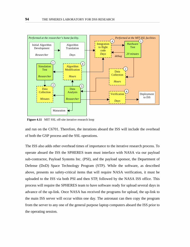
94 THE SPHERES LABORATORY FOR DSS RESEARCH
and run on the C6701. Therefore, the iterations aboard the ISS will include the overhead
of both the GSP process and the SSL operations.
The ISS also adds other overhead times of importance to the iterative research process. To
operate aboard the ISS the SPHERES team must interface with NASA via our payload
sub-contractor, Payload Systems Inc. (PSI), and the payload sponsor, the Department of
Defense (DoD) Space Technology Program (STP). While the software, as described
above, presents no safety-critical items that will require NASA verification, it must be
uploaded to the ISS via both PSI and then STP, followed by the NASA ISS office. This
process will require the SPHERES team to have software ready for upload several days in
advance of the up-link. Once NASA has received the programs for upload, the up-link to
the main ISS server will occur within one day. The astronaut can then copy the program
from the server to any one of the general purpose laptop computers aboard the ISS prior to
the operating session.
Figure 4.11 MIT SSL off-site iterative research loop
Performed at the MIT SSL facilitiesPerformed at the researcher’s home facility.
Initial AlgorithmDevelopment
Researcher
AlgorithmTranslation
Days
HardwareTest
20 minutes
DataCollection
Hours
Maturation
AlgorithmModification
Hours
2
4
DataAnalysis
Researcher
3
Integrationto flight
codeDays
4 1
debug
Verification
Days
Deploymentto ISS
4
SimulationTest
Researcher
1
DataCollection
Minutes
2

Meeting the MIT SSL Laboratory Design Philosophy 95
Data download will also have added overhead, since both PSI and STP must be involved.
Further, the data down link from the ISS is not necessarily real time. For the majority of
the SPHERES operations NASA has indicated a one day download time of raw data
(including astronaut questionnaire and feedback), and a two to three day video download.
The data must then pass through STP and PSI before reaching the SPHERES team and/or
researcher (in some cases PSI may send data directly to the researcher).
As explained in Chapter 2, astronaut time is a precious resource aboard the ISS.
SPHERES has been allocated a fixed time for operations over a period of six months. The
SPHERES team decided to allocate the time in intervals of two hours of operations every
two weeks. This time will be fixed by NASA once operations start (although SPHERES
operations may be preempted by other NASA activities). Therefore, the minimum time for
data analysis and algorithm modification for researchers will come in intervals of two
weeks. A scientist may decide to have the time between iterations be every two, four, even
six weeks or more depending upon their needs, but not less than two weeks.
While the total time per session is two hours, one must recall that the limiting factor for
each test are the consumables. Specifically, the available propellant in each tank is esti-
mated to last for up to 30 minutes (depending heavily on controller usage). Therefore,
each test can be at most 30 minutes long, assuming conservative gas consumption and that
a new tank was used at the start of the test. Longer tests may be possible for minimal gas
consumption. At that point, the limiting factor becomes the batteries, which last up to two
hours, regardless of the maneuvers of the satellites.
At this point it is important to note that, while in ground operations the time to upload a
program to the SPHERES satellites was considered negligible, this can no longer be
ignored in the ISS. Uploading a program takes up to five minutes per satellite that must be
programmed. Therefore, for a three satellite test, the overhead will be up to 15 minutes;
this is a considerable amount of time out of the two hours allocated per session. Therefore,

96 THE SPHERES LABORATORY FOR DSS RESEARCH
the SPHERES operational plans call for no more than two programs (each with multiple
tests) to be uploaded per session.
Figure 4.12 on page 97 presents the ISS iterative research process graphically. The pro-
cess starts at the researcher facilities utilizing the GSP simulation. The total overhead at
this point is in terms of hours to run enough simulations and debug software. The process
continues with the delivery of the software to the MIT SSL for integration into a flight
package. This process will add several days of overhead to ensure the software is ready for
delivery. Once validated, the program is sent to the ISS via PSI/STP/JSC, for a total over-
head of approximately two days. The astronaut, once scheduled to operate SPHERES,
copies the program to a local laptop and loads the program, for a total overhead of approx-
imately 15 minutes. A cycle of tests follows; multiple tests are run, guided by the astro-
naut's decisions and the operations plans provided by the scientist. The data collected on
the ISS laptop is copied to the main ISS server immediately after the session in a matter of
minutes; the data is made available to STP/PSI by JSC within one day. Within another day
the data reaches the researcher, for a total data download overhead of approximately two
days. The video is downloaded from the ISS in approximately two or three days, and made
available in digital format to STP/PSI in another few days. In total, the video of a test ses-
sion is expected to be available within one week of the test session. The researchers are
expected to operate on a four or more week cycle to allow sufficient time for data analysis
and algorithm modifications.
4.3.1.2 Continuous visual feedback
A major obstacle to maturate technologies via simulation is the inability to fully under-
stand the dynamics of a system and visualize them properly. SPHERES provides research-
A multi-layered operations plan allows scientists to perform research iterationsin-house, remotely and locally at the MIT SSL, and remotely at the ISS. Theiteration period ranges from hours to a flexible 2-week schedule for operationsaboard the ISS.
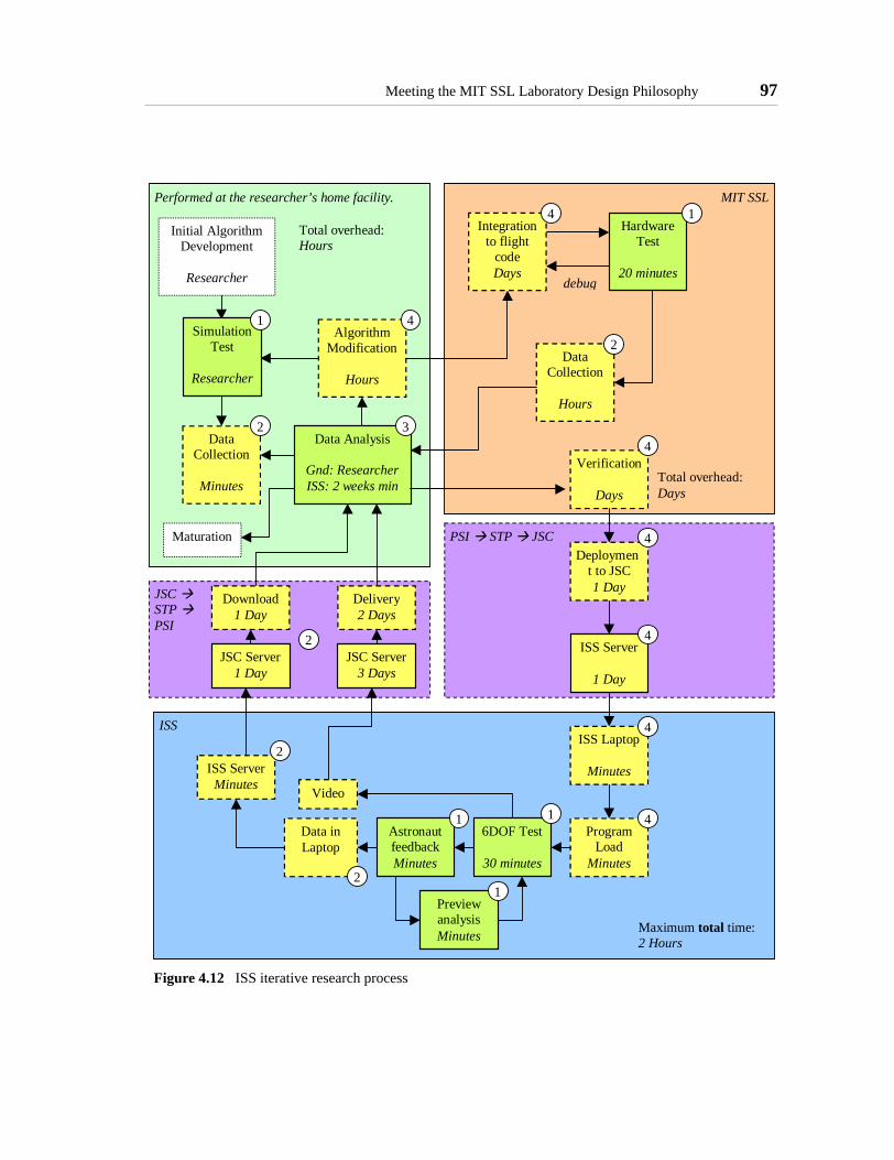
Meeting the MIT SSL Laboratory Design Philosophy 97
Figure 4.12 ISS iterative research process
PSI STP JSC
MIT SSLPerformed at the researcher’s home facility.
Initial AlgorithmDevelopment
Researcher
HardwareTest
20 minutes
DataCollection
Hours
Maturation
AlgorithmModification
Hours
2
4
Data Analysis
Gnd: ResearcherISS: 2 weeks min
3
Integrationto flight
codeDays
4 1
debug
Verification
Days
Deployment to JSC1 Day
4DataCollection
Minutes
2
Total overhead:Hours
Total overhead:Days
4
ISS Server
1 Day
4
ISSISS Laptop
Minutes
4
ProgramLoad
Minutes
4
Maximum total time:2 Hours
6DOF Test
30 minutes
1AstronautfeedbackMinutes
Data inLaptop
1
2
PreviewanalysisMinutes
1
Video
JSC STP PSI
ISS ServerMinutes
JSC Server1 Day
JSC Server3 Days
Download1 Day
Delivery2 Days
2
2
SimulationTest
Researcher
1

98 THE SPHERES LABORATORY FOR DSS RESEARCH
ers with a physical system where they can carefully study the behavior of the satellites.
When the researcher is present, they can directly identify the dynamic behavior of the sat-
ellites, which allows them to quickly determine the success of a test. Further, they obtain
much more insight into the actual three dimensional behavior of the units, even if conduct-
ing tests in the 2D ground facilities. When SPHERES is operated remotely of the
researcher, the facility always provides researchers with two visual feedback elements: a
human is always present to evaluate tests in real-time, and video will always be available.
In many cases video is available from multiple angles (including ISS video), which can
potentially be used for data analysis.
The ability of SPHERES to minimize the data collection overhead time is directly related
to the availability of visual feedback and video in all locations. The physical operations
provide the researchers with immediate feedback to make rough determinations of success
or failure of the experiments. Since the SPHERES facility was designed for the develop-
ment of dynamics algorithms, in many cases it will be clear from the video when an exper-
iment succeeds or not, since specific motions will be expected. Using video the scientist
can then determine which data sets to investigate further, saving time by not having to
analyze every single data set.
4.3.1.3 Families of tests
The SPHERES software enables researchers to run a full family of tests with ease. The
SPHERES software consists of programs that contain multiple tests. At any point in time
only one program can be loaded into a SPHERES satellites. The program can be changed
easily with the bootloader, described in Section 4.3.4.7 below. But changing a program
does have a two to five minute overhead, which, as described above, is not negligible in
the ISS environment. Therefore, to minimize the overhead in starting experiments,
SPHERES allows each program to perform multiple tests.
Continuous visual feedback by humans allows scientists to reduce the datacollection overhead time by filtering useful experiment runs.
Meeting the MIT SSL Laboratory Design Philosophy 99
Theoretically the different tests in each program can be completely independent of each
other; in practice the SPHERES team attempts to maintain similarity between the different
tests in each program to minimize the size of the program and to ensure that subsequent
tests make sense operationally. In the case of a controls problem, for example, a program
may contain multiple tests of the same algorithm with different gains for the controller;
but the tests could also sequentially build on the controls problem, adding steps with each
test. The ability to run these families of tests sequentially, without any substantial over-
head, allows for different parts of an algorithm to be tested individually and then collec-
tively, until the full algorithm is demonstrated.
Individual tests can be further divided into maneuvers. Each test can contain one or more
maneuvers, allowing the researcher to further divide the test and identify up to what
maneuver a test performed as expected. As opposed to tests, which can be started in any
order, the user does not have control to start a test at a specific maneuver; tests must
always start with the first maneuver. But the software architecture allows maneuvers to be
shared among tests, and a researcher can create tests with overlapping maneuvers to test
different parts of an algorithm.
Figure 4.13 illustrates the structures of programs as implemented in the SPHERES soft-
ware environment, and describes an example for the "checkout" program. This program
tests the different sub-systems of the SPHERES satellites independently of each other,
therefore demonstrating the ability of one program to perform substantially different tests.
Operationally, though, the checkout program is congruent, as the operator will clearly
identify each sub-system with a test. The example also shows how maneuvers can be used
to simplify test design. In the checkout program the "global metrology" test, which checks
the functionality of the ultrasound receivers in the satellites, uses maneuvers to keep track
of which satellite face is being tested, rather than having to create special telemetry.
The implementation via families of tests and ability to change programs further facilitates
the iterative research process by effectively allowing the software to be modified at any

100 THE SPHERES LABORATORY FOR DSS RESEARCH
level. When considering steps three and four, algorithm modification and test implementa-
tion and setup, this design gives the scientist several advantages. During the algorithm
modification time the scientist can decide to review only specific maneuvers, combine
tests, or even redefine the program completely. There is no overhead in terms of reloading
the program to choose any level of modification (albeit, small changes result in the need to
load the full program again). By allowing the scientists to modify their algorithms at any
level, SPHERES maximizes the time scientists can spend in re-defining their algorithms,
rather than implementing them. The software sub-system ensures that the iterative process
is not slowed down whether small or large changes are needed.
4.3.1.4 Easy repetition of tests
Chapter 3 reviewed two essential concepts in conducting research: the scientific method
and the design of experiments. The operations plan presented above works to fulfill the
Figure 4.13 SPHERES programs composition
Running families of tests minimizes the overhead to start a test and allowsmultiple parts or types of algorithms to be tested in one session. The layered program structure enables both small and large changes to thealgorithms.
One program is loadedon the satellites at atime
Programs consists ofmultiple tests, selectedin any order toaccommodate real-time results
A tests consists of oneor more maneuvers toidentify test progress.
Program: Checkout
Test: Fire Thrusters
Maneuver: Fire
Test: Check Global Metrology
Maneuver: Face X+
Maneuver: Face Y+
Example:• The “Checkout” program tests all
sub-systems, including propulsionand metrology; to test all sub-systems only this one programneeds to be loaded to a satellite
• The propulsion test has only onemaneuver, to fire all thrusters; theastronaut can run the test multipletimes at any point
• The metrology test has onemaneuver for each face of thesatellite; the standard telemetrywill indicate which face was beingtested by saving the maneuvernumber, without the need forspecial telemetry

Meeting the MIT SSL Laboratory Design Philosophy 101
need of the scientific method to iteratively improve a hypothesis. The design of experi-
ments, on the other hand, closely relates to the ability to conduct the correct number of
tests, with a number of variables, to demonstrate the statistical viability of a hypothesis.
This concept lies within step one and four of the iterative process presented in Figure 4.8
on page 88: minimize the time to setup a test to maximize the science time. To accomplish
this goal, the design of SPHERES ensures that it is possible to repeat tests with ease.
This repetition of tests takes place within a specific program; the times to minimize are the
ones involved with setting up the units for a test and commanding the start of the test.
Starting a test with SPHERES consists of four simple steps:
1. Check battery and gas pressure: visual feedback of both available battery(low battery indicator) and gas tank contents (estimated use) allow thischeck to take place in seconds.
2. Enable the satellite (mandatory only in the ISS): for safety reasons the satel-lite must be enabled prior to any actuation. This process requires the astro-naut to depress the enable button for more than one second.
3. Position the satellite correctly: this is potentially the most time-consumingpart, since it is desired that all tests of the same algorithm start with similarconditions. Still, the small physical size of the satellites (both mass and vol-ume) allows easy manipulation so that similar starting conditions can beachieved. Tests in the ISS by astronauts, with objects of similar size to theSPHERES satellites, have demonstrated that preventing drift of one unitwhile other units are re-positioned does not pose a challenge.In the case of ground tests, positioning the satellites also requires positioningtheir air carriages correctly and turning on the gas for the carriages. This pro-cess takes only a few seconds for one or two SPHERES, although it can posean operational challenge for three or more units. Ground tests have shownthat the air-carriages do drift once floating, and therefore require morehuman attention to ensure a successful start.
4. Command test start: the ground-based interfaces command a test start withthe simple press of one key. The ISS interface requires two steps to satisfysafety requirements. (Both interfaces are described in further detail below).
The total time to start a test is less than one minutes in ground stations when using up to
two satellites, and approximately one to two minutes for the ISS. When using three or
more satellites in ground facilities it may take up to five minutes to start a test, depending

102 THE SPHERES LABORATORY FOR DSS RESEARCH
on the conditions of the surface where the carriages are floating and the amount of drift
experienced.
Another important aspect of repeating multiple tests easily is the ability to stop a test that
has gone wrong and reset the facility for the next test. SPHERES allows multiple ways to
stop a test and setup the facility ready for a new test. The software can restart a test in mul-
tiple scenarios. The researcher can program special conditions which cause a test to auto-
matically end, leaving the satellite ready for the first step of setup. The software
implementation ensures that a test stop will not affect the behavior of the rest of the sys-
tem. This feature allows tests to be run only as long as necessary, allowing tests to be
stopped if they fail in an obvious manner, while ensuring the data is safely archived for
post-examination. A remote restart command, which causes the units to re-start in a man-
ner equivalent to cycling the power, was implemented in case the satellites are out of
reach. The satellites’ control panel allow the scientist to disable the current test, which
does not perform an actual reset of the avionics, or to reset the unit completely, also equiv-
alent to cycling power. Through these four different reset scenarios SPHERES allows a
scientist to both stop tests without affecting the state of the avionics or to fully cycle the
satellites for a clean start.
The ability to physically restart a test is not useful unless it is possible to identify which set
of data corresponds to each test. SPHERES transmits multiple telemetry packets which
clearly identify each run of a test, regardless of whether a previous test initiated, ran, or
concluded as expected. The system is further enhanced by the different operator inter-
faces, all of which save all raw data, allowing for error-correction in post-test analysis.
SPHERES implement these features by creating a high-level state machine as part of the
basic SPHERES software and utilizing the external watchdog of the avionics system to
force resets. Figure 4.14 illustrates the state machine implemented by the software. Four
states are implemented: boot time, which initializes the satellites and load the current pro-
gram; idle, which does not perform any actuation and which is not running any user

Meeting the MIT SSL Laboratory Design Philosophy 103
threads (see figure Figure 4.5 on page 79), but which sends the "state of health" (SOH)
information once a second, which saves the current state, the satellite on-time, and tank
usage, among others; the "ready" state is an intermediate step which allows a test start
command to be acknowledged, but which otherwise is not functionally different from idle;
the running state, which starts after a command has been acknowledged, first runs the test-
specific initialization code, and then start the user threads. If the researcher programmed
their test-specific initialization code correctly, then whenever the satellite starts a new test
the conditions of the satellite will be the same. Note that the SOH packet downloads full
test information when a test is running, so that each test can be clearly identified.
4.3.1.5 Direct link to ISS data transfer systems
While both video and experiment data are easily available in ground testbeds through
local computers and camcoders, the iterative research process can be greatly disturbed by
lag of data transfer while operating aboard the ISS. Previous experience taught the
SPHERES team to minimize the need for communications hardware outside of the avail-
able ISS resources, such as using our own hardware for storage of data and/or requiring
transfer of physical items such as CD’s or video tapes. Therefore, the SPHERES maxi-
mizes the use of ISS resources to minimize the amount of time spent transferring data
between systems, while at the same time balancing the fact that this makes the collection
of SPHERES data and video dependent on a third party (NASA).
The SPHERES facility utilizes an ISS laptop as the control station. The SPHERES inter-
face runs directly on that laptop; all the data received by the laptop are saved directly to
the laptop (at the end of an ISS test session a single compressed file collects all the data).
NASA has provided the SPHERES team with a shared drive for use, which means the
SPHERES data files will have a direct link to the main ISS server. Under normal opera-
The SPHERES state machine implementation, coupled with hardware resetcapabilities, ensures that tests can be stopped and started with minimaloverhead.

104 THE SPHERES LABORATORY FOR DSS RESEARCH
tions the astronaut will not need to transfer files manually, the operation occurs automati-
cally. The data from the main ISS server is downloaded every day by JSC. At that point
the team depends on the JSC staff to forward the data to the SPHERES team; this usually
occurs within 24 hours.
Figure 4.14 SPHERES satellites initialization
SAT INIT- Load current program- Initialize memory
IDDLE- No user threads running- Basic telemetry (1Hz)
READY- No user threads running- Basic telemetry (1Hz)
RUNNING- Basic telemetry (1Hz)
Test Init
Control
Metrology
Background Tasks
Turn on /Power Cycle
Enable button
Start command
Res
et b
utto
nR
eset
Com
man
d
SW S
top
Enab
le B
utto
n
Telemetry
SOH (1Hz)- iddle- SPH time
CommandAcknowledgement
Test Start
SOH (1Hz):- Running- Sat Time- Test #- Test time- Man #- Man time
SOH (1Hz)- ready- SPH time
SOH = “State of Health” packet
~ 3s
~ 2s
~ 1s
Position Satellites~ 1-5min
~ 5s Tank/Bat check
Boot time

Meeting the MIT SSL Laboratory Design Philosophy 105
SPHERES also utilizes the ISS video capabilities for both capture and download. While
this process can take longer than data download, it is still faster than any custom solution.
Utilizing the ISS existing hardware prevents the need for further mass/volume if
SPHERES custom video equipment were required. To obtain reasonable download times
the ISS data system would still have to be used for video download, possibly slowing
down the transfer of data overall. Because downloading server data and video are separate
processes at NASA, the use of the ISS video system decouples the download of the two
sets of feedback.
As a result SPHERES does not require of any data transfer between custom media and
does not need to wait for the physical return of any data storage facility. The only
SPHERES specific communications hardware is the STL (Satellite-to-laptop) transmitter,
which connects directly to the ISS laptop.
4.3.1.6 De-coupling of software with NASA safety controls
Throughout the development of the SPHERES facility great care was taken to ensure that
the software was not part of NASA's safety controls. As explained above, the software
facilitates the iterative research process by allowing scientists to change their implementa-
tion at many levels. If the scientist discover that only small changes are needed, but the
SPHERES software had to go through NASA safety reviews to be implemented, then the
overhead for small changes would be disproportional to the changes. To ensure that the
implementation step during ISS operation remains reasonable, it was essential for the
SPHERES software to remain independent of NASA safety controls.
To achieve this goal the hardware sub-systems provide the double and triple redundancy
required by NASA. The NASA safety reviews concentrated on the propulsion, power, and
communications sub-systems, on the fact that the SPHERES satellites are free-floating in
A direct link to the ISS data system minimizes the time to collect microgravitydata and requires no transfer of physical media.

106 THE SPHERES LABORATORY FOR DSS RESEARCH
the ISS, and on the noise levels produced by the satellites and metrology hardware
[SPHERES, 2001].
The propulsion system provides hardware relief valves to ensure that the unit is not depen-
dent on the software to vent the unit in case of pressure build-up. Further, even though not
required by the NASA safety review panel, the propulsion hardware driver circuits
defaults to an off state, such that resetting the SPHERE will always close the solenoids
and stop any firings, independent of test-specific software. Lastly, the amount of thrust
exhibited by the satellites is such that an astronaut can hold a satellite until the gas tank
depletes without any hazards. The power system provides hardware current limiting
devices directly in the battery packs (redundant), a magnetic circuit breaker, and always
operates below 32V. These specification mean that the software can never cause a safety
hazard situation due to electrical power. The communications system defaults to idle
mode, and requires initialization from the software. Further, the reset signal is sent inde-
pendently to the communications hardware, ensuring that a reset forces communications
to stop regardless of the state of the software. Lastly, the dynamics of each satellite were
designed so that even in the case of a software failure any collision is under the limits
specified by NASA and the noise produced by the satellites was designed to be below
NASA requirements during all types of operations, including excessive thrusting. These
measures ensure that once a researcher decides to change a program, this can be uploaded
to the SPHERES project without any delays due to software reviews.
A further benefit of the lack of safety checks for the ISS is their applicability to operations
in multiple NASA locations, including the KC-135 Reduced Gravity Airplane. The soft-
ware cannot cause any hazards by itself, and therefore does not require verification. The
lack of safety controls in the software ensures that such lag does not exist, and that the iter-
ative research process is only affected by the availability of communications links to and
from the facility.

Meeting the MIT SSL Laboratory Design Philosophy 107
4.3.2 Support of Experiments
The need to repeat experiments in an efficient matter is an essential part of the iterative
research process. As presented in Chapter 3, the "support of experiments" features directly
affect the ability to enable the iterative research process, but they go into further detail on
how to achieve efficient tests than the high-level feature of "facilitating the iterative
research process". The last section presented the high level operations plan and other spe-
cial characteristics of SPHERES which facilitate the iterative process over all. This sec-
tion will present in more detail the several specific functions of SPHERES that directly
affect its ability to run an experiment correctly and efficiently.
The following functionalities of SPHERES enable it to support conducting experiments:
• Data Collection and Validation Features
- Layered metrology system
- Flexible communications: real-time & post-test download
- Full data storage
- 32 bit floating point DSP
• Redundant communications channels (reliability)
• Test management & synchronization (repeatability)
• Location specific GUI’s (human observability & manipulation)
• Re-supply of consumables (repeatability, supporting extended investiga-tions, risk-tolerant environment)
• Operations with three satellites (reliability, risk tolerant environment)
• Software cannot cause a critical failure (risk tolerant environment)
4.3.2.1 Layered metrology system
Chapter 3 calls for the following requirements on data collection (among others):
• Ensure data accuracy and precision scalable to the final system
De-coupling all safety controls from the software minimizes the overhead todeploy new algorithms and allows scientists to program algorithms that pushthe limits of the theory without delaying the iterative research process.

108 THE SPHERES LABORATORY FOR DSS RESEARCH
• Ensure observability of the technology
Developing the SPHERES environment presented a major challenge in the development
of a valid metrology system. Not only was a 6DOF measurement system for use inside the
ISS was not available "off-the-shelf", but the design of SPHERES called for it to be a
development testbed for metrology algorithms itself. Therefore the metrology system had
to provide scientists with both the necessary data and computation power to both develop
new metrology algorithms and to trust the data if they use the SPHERES provided proce-
dures.
To obtain the accuracy and precision scalable to the final system the SPHERES metrology
system utilizes a two-layer implementation. High-frequency accelerometers and gyro-
scopes capture the inertial motion of the satellites. The selection of the COTS accelerome-
ters and gyroscopes was driven by the need to provide accurate data for the expected
motion of the satellites using the cold gas thrusters. With a thrust of approximately 0.125N
and a mass of 4kg per satellite, each thruster would cause an on-axis acceleration of
approximately 0.03125 m/s2; the thrusters are located approximately 0.125m off axis, pro-
viding a torque of approximately 0.004Nm, which equates to a rotational acceleration of
0.25rad/s2. Therefore, the accelerometer must measure 3.2mg’s, while the gyroscope
range was selected as ±50°/s (~0.9rad/s) since the expected thrust periods are no longer
than one second (which results in approximately 30°/s with two thrusters firing on axis).
Table 4.6 summarizes the satellite dynamics under thruster actuation.
TABLE 4.6 Satellite dynamics under actuation
ValueSingle thruster force 0.125N
Minimum opening time 10msAcceleration 0.03125m/s2 (~3.2mg’s)
Rotational speed (minimum impulse) 0.25rad/s2

Meeting the MIT SSL Laboratory Design Philosophy 109
The gyroscope selection was relatively straight forward, as the range of rotation rate was
easily available from COTS equipment and the thrusters have a large enough level arm to
easily excite the single-bit resolution of a wide range of gyroscopes. The final selection
took place for their size and small drift which allows rotational control of the units for
extended periods without the need for the global metrology system. The gyroscope speci-
fications are presented in Table 4.7.
The selection of the accelerometer presented a bigger challenge, since the thrusters linear
acceleration is in the milli-g’s range. Therefore the selection had to trade-off between
selection accelerometers which would provide feedback on external disturbances (such as
collision of two units at dock time or forces by humans) or from the thruster firings. The
final selection gave priority to measuring thruster actuation. The accelerometer will satu-
rate whenever external forces, which will be much larger than the thruster forces, are
applied; the saturation of the accelerometers can be used as a binary method to detect
external forces, even if not to model them. The characteristics of the accelerometer selec-
tion are presented in Table 4.8.
Testing of the gyroscopes and accelerometers in the KC-135 reduced gravity airplane
showed the ability of the sensors to detect the thrusters. Figure 4.15 plots sample data
from the micro gravity tests. The data are from testing firing thrusters number zero and
one, which produce acceleration on the X axis and rotation about the Z axis. The top plot
presents the accelerometer readings; the bottom plot the gyroscope data. While in an ideal
TABLE 4.7 Gyroscope specifications (BEI Gyrochip II)
Specification ValueInput range ±50°/sScale Factor 30mV/(°/s)
Bias stability (<100s) 0.05°/sBandwidth 50Hz
Sensitivity (12bit A2D) 0.0407(°/s)/bit
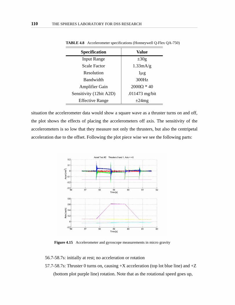
110 THE SPHERES LABORATORY FOR DSS RESEARCH
situation the accelerometer data would show a square wave as a thruster turns on and off,
the plot shows the effects of placing the accelerometers off axis. The sensitivity of the
accelerometers is so low that they measure not only the thrusters, but also the centripetal
acceleration due to the offset. Following the plot piece wise we see the following parts:
56.7-58.7s: initially at rest; no acceleration or rotation
57.7-58.7s: Thruster 0 turns on, causing +X acceleration (top lot blue line) and +Z
(bottom plot purple line) rotation. Note that as the rotational speed goes up,
TABLE 4.8 Accelerometer specifications (Honneywell Q-Flex QA-750)
Specification ValueInput Range ±30gScale Factor 1.33mA/gResolution 1µgBandwidth 300Hz
Amplifier Gain 2000Ω * 40Sensitivity (12bit A2D) .011473 mg/bit
Effective Range ±24mg
Figure 4.15 Accelerometer and gyroscope measurements in micro gravity

Meeting the MIT SSL Laboratory Design Philosophy 111
the off-axis effects cause the +X acceleration to go down. Also note that
thruster zero causes a small effect on the Z axis accelerometer.
58.7-59.7s: All thrusters are off again; note that the accelerometers do not return to
zero because of the rotation of the unit.
59.7-60.7s: Thruster one turns on, stopping the rotation of the unit. The effect of
the thruster is not seen much in the accelerometer in absolute numbers
because the acceleration due to rotation was similar to that caused by the
thruster; the effect is seen my the difference in accelerometer readings
between the past period and this period.
60.7-61.7s: The units return to rest; with no more rotation the accelerometers
return to their zero state values.
A simplistic model of the SPHERES satellites which does not account for the coupling
between rotational speed and the accelerometer readings would not be able to use the
accelerometer data. Therefore, while the accelerometers can provide full observability of
the system, this is only true if the correct model of the satellites is used.
A low-frequency ranging system uses a combination of infrared and ultrasound signals to
measure distances using the "time-of-flight" of the ultrasound signals and provide position
and angular direction in 6DOF within a pre-defined operating area. Five external transmit-
ters are used. An infrared pulse (treated as instantaneous) commands the start of ultra-
sound pulses and marks time "zero". The transmitters pulse one at a time in 20ms
windows (allowing up to 6m of travel by the ultrasound). Each satellite uses 24 ultrasound
receivers, four per face, allowing scientists to use the information for both triangulation of
position and differential measurement for angular direction. Scientists can use the direct
measurements or filtered data as best fits their application. Figure 4.16 illustrates the raw
distance measurements of the global metrology system. The system provides resolution of
±5mm and ±2° in a 3m by 3m space.

112 THE SPHERES LABORATORY FOR DSS RESEARCH
Although the actual observability of the system depends on the implementation of the
model by each scientist, the SPHERES metrology system allows measurement of all the
elements of a standard state vector for dynamics and control for a second order rigid body
system such as a SPHERES satellite: position and velocity (linear and angular).
Figure 4.17 illustrates how the state vector for each satellite can be filled by the use of the
global metrology system and the inertial measurement sensors.
Each satellite also includes its own beacon to accommodate a different type of state vec-
tor: differential states between two satellites. This state vector can be used in the develop-
ment of docking algorithms as well as formation flight maneuvers which require direct
measurements between satellites, rather than by finding the differences using the global
system. Figure 4.18 illustrates how the metrology system can be used to fill the state vec-
tor between two different satellites. The satellite beacon systems have a limitation due to
the beacon location (directly on the X axis): it is not possible to use the pathlength differ-
ences to determine the attitude between the two satellites along the X axis.
4.3.2.2 Flexible communications: real-time & post-test download
Selection of metrology is not good enough. We need to make sure we can save all the data
we need. The team had to recognize the limitation of the wireless communications band-
width and account for that. Therefore the communication system is flexible in several
Figure 4.16 Global metrology system time-of-flight distance measurements

Meeting the MIT SSL Laboratory Design Philosophy 113
ways: it has two types of data download (real-time and post-test) and can use custom pro-
tocols for inter-satellite communications.
The real-time data download must be transmitted within the TDMA windows of the satel-
lites, meaning that data can be sent between units at up to 5Hz (200ms frames). Each com-
munications packet consists of up to 32 bytes of data and takes approximately 15ms to
transmit. The total amount of data that can be transferred in real time ranges from 320
bytes at 5Hz (12.8kbps) for one unit to 64 bytes at 5Hz (2.56kbps) for five units. Since
synchronization of the STL channel with the laptop is essential for the test management
elements of the SPHERES software, the STL channel must always remain under the
TDMA protocol and strictly limited to these data rates.
Figure 4.17 Measuring the state vector with the layered metrology system
⎥⎥⎥⎥⎥⎥⎥⎥⎥⎥⎥⎥⎥⎥⎥⎥⎥
⎦
⎤
⎢⎢⎢⎢⎢⎢⎢⎢⎢⎢⎢⎢⎢⎢⎢⎢⎢
⎣
⎡
=
z
y
x
zyx
zyx
x
ωωω
ψϑθ
&
&
&
• Directly measured by global metrology system.• Although theoretically obtainable from double-integration of the
accelerometer, practically it is not useful.
• Directly measured by global metrology system.• Can successfully integrate the gyroscope over periods of at least 10
minutes.
• Differentiate global metrology measurements.• Can integrate accelerometer once in micro gravity conditions
through periods without actuation.
• Can differentiate global metrology measurements, with limited trust.• Directly measured by the gyroscope over extended periods of time.
⎥⎥⎥⎥⎥⎥⎥⎥⎥⎥⎥⎥⎥⎥⎥⎥⎥
⎦
⎤
⎢⎢⎢⎢⎢⎢⎢⎢⎢⎢⎢⎢⎢⎢⎢⎢⎢
⎣
⎡
=
z
y
x
zyx
zyx
x
ωωω
ψϑθ
&
&
&
&&
&&
&&
&
&
&&
&
&
& • Theoretically obtainable from double differentiation of globalmetrology, but not practical.
• Directly measured by the accelerometers.
• Theoretically obtainable from double differentiation of globalmetrology, but not practical.
• Can differentiate the gyroscope measurements over extended periodsof time.

114 THE SPHERES LABORATORY FOR DSS RESEARCH
The communications bandwidth creates a necessity to trade-off data download and opera-
tions time. The communications bandwidth is large enough to help scientists see real-time
results of debug and processed data in the laboratory environments and to capture pro-
cessed data in the space environment (since many of the algorithms will have been tested
to trust the data). But it can be too limiting for tests which require high frequency data cap-
ture or when several units are used. When low-frequency data capture is enough or once
processed data provides the necessary information, all data download can occur in real-
time. But if large amounts of data must be saved to provide the necessary information,
SPHERES allows scientists to download the data after a test concludes.
Of the 16MB of RAM available in each satellite, up to 10MB are available for data manip-
ulation and storage (depending on the specific program). This memory can be allocated
both statically or dynamically to create one or more data buffers. A test can be pro-
Figure 4.18 Differential measurements between two satellites.
The SPHERES layered metrology system allows full observability of a secondorder rigid body system in an inertial and a reference frame.The satellite beacon system further allows limited direct measurement ofdistances and angles between two satellites.
⎥⎥⎥⎥⎥⎥⎥⎥⎥⎥⎥⎥⎥⎥⎥⎥⎥
⎦
⎤
⎢⎢⎢⎢⎢⎢⎢⎢⎢⎢⎢⎢⎢⎢⎢⎢⎢
⎣
⎡
=
z
y
x
z
y
x
z
y
x
vvv
ddd
x
ωωω
ψϑθ
• Directly measured by satellite beacon system.
• Directly measured by global metrology system.
• Differentiate satellite beacon measurements.
• Cannot be measured by satellite beacon system.
• Can differentiate satellite beacon measurements.• Directly measured by gyroscopes.
• Cannot be measured by satellite beacon system.• Directly measured by gyroscope.

Meeting the MIT SSL Laboratory Design Philosophy 115
grammed to continue until all the buffer is emptied, even if the actuation maneuvers have
ended. Further, the test management portion of the SPHERES core software can be pro-
grammed so that after a test is run the data buffer is left intact and a second test can then be
run to download the data buffer; this buffer can be shared among multiple tests and as long
as the download test is run in between all other tests the data will be safely downloaded.
This operating scenario presents a trade-off: utilizing operations time solely to download
data rather than to test more algorithms. Scientists will have to balance their need for high-
frequency unprocessed data and the available time to operate the satellites. Figure 4.19
presents a sample algorithms where tests 1...N-1 run algorithms and collect large amounts
of raw data in two satellites. Tests N and N+1 are run after each of the other tests to down-
load the data. The time spent on tests N and N+1 must be considered as an overhead to the
iterative process, but could be essential for the science.
To accomplish this the communications functions interface with the data solely via point-
ers, rather than by copying data from the original location to a communications buffer.
Doing this minimizes the memory space used by the communications interfaces, but it
also places the responsibility on the scientists to ensure the data remains safe prior to its
transfer. The core software implements four mailboxes of 20 packets; these mailboxes are
managed internally by the software to accommodate data of two different priorities in the
two communications channels, but are not available as storage space for the user. The
SPHERES software routines copy the data from the memory separated by the user to these
mailboxes automatically, and transmit the data out of the mailboxes following the TDMA
protocol.
The flexibility of the communications system is further enhanced by the ability to use the
STS channel using custom protocols and software. While the STL channel is constrained
to use the TDMA protocol, the STS channel can be programmed differently and indepen-
dently. The core software implements a TDMA protocol by default, also operating at 5Hz.
The lack of a ground station (the laptop) allows inter satellite communications to use the
full window to transfer data, with data rates ranging from 2.56kbps per satellite for trans-
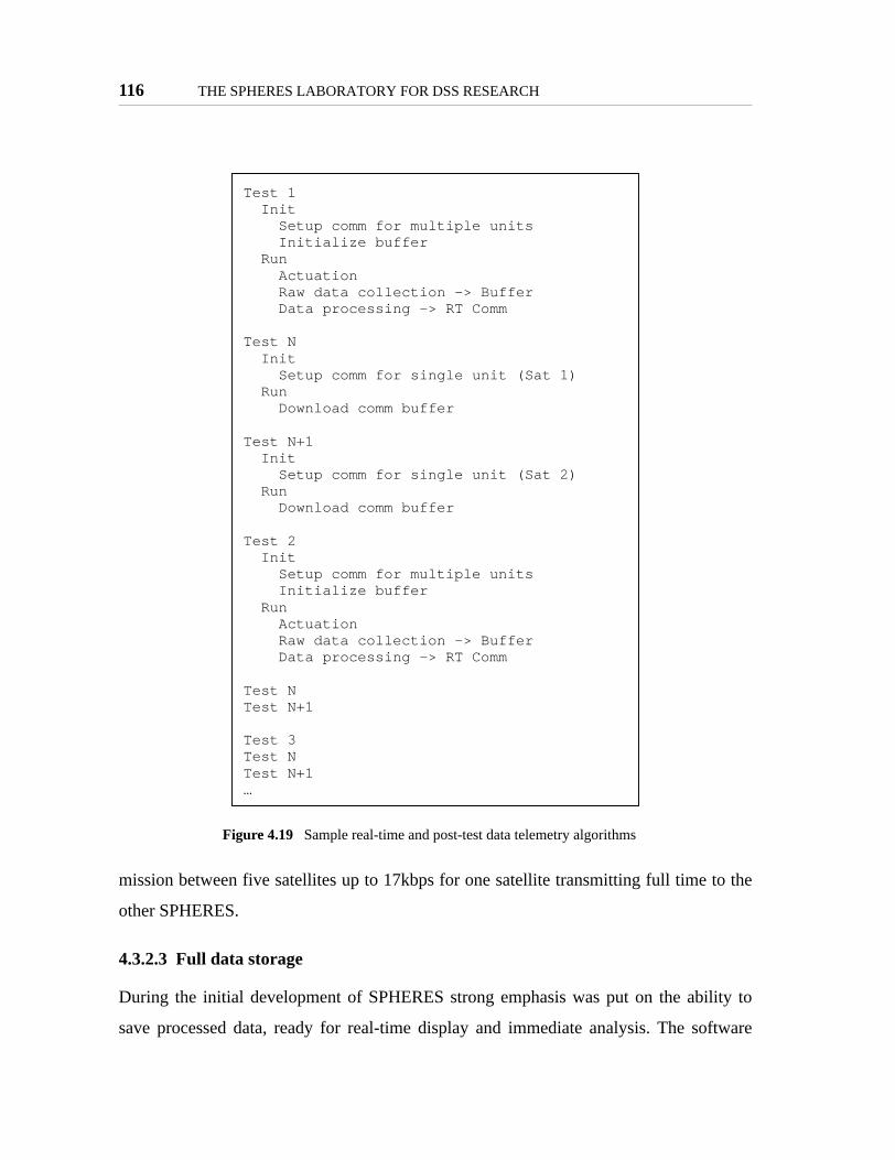
116 THE SPHERES LABORATORY FOR DSS RESEARCH
mission between five satellites up to 17kbps for one satellite transmitting full time to the
other SPHERES.
4.3.2.3 Full data storage
During the initial development of SPHERES strong emphasis was put on the ability to
save processed data, ready for real-time display and immediate analysis. The software
Figure 4.19 Sample real-time and post-test data telemetry algorithms
Test 1 Init Setup comm for multiple units Initialize buffer Run Actuation Raw data collection -> Buffer Data processing -> RT Comm
Test N Init Setup comm for single unit (Sat 1) Run Download comm buffer
Test N+1 Init Setup comm for single unit (Sat 2) Run Download comm buffer
Test 2 Init Setup comm for multiple units Initialize buffer Run Actuation Raw data collection -> Buffer Data processing -> RT Comm
Test NTest N+1
Test 3Test NTest N+1…
Meeting the MIT SSL Laboratory Design Philosophy 117
which operated in the laptop would not only receive the data and check the packet integ-
rity, it would also translate the raw binary data into special structures such as the state of
the satellites; the software would only save the processed data. This practice proved to be
too restrictive as any change in the communications structures would require not only to
modify the software of the satellites, but also the software of the laptop (during the proto-
typing stages of SPHERES there were at least six version of the laptop software, depend-
ing on the data to be saved).
To facilitate data collection of any type the SPHERES communications design defines
only a limited number of special packets; further, all data is saved in its raw form as
received by the communications hardware. The special SPHERES packets are:
• General Purpose Commands - outgoing: from the laptop to the satellites.These packets send the satellites information on starting and stopping a test,resetting the units and/or control variables, and starts a frame. The packet istransmitted at 5Hz from the laptop.
• Initialization Packet - outgoing: from the laptop to the satellites. These pack-ets transmit the measured setup of the metrology transmitters such that thesatellites can use the global metrology system.
• State of Health - incoming: from the satellites to the laptop. The SPHEREScore software automatically transmits its state of health at 1Hz. The packettransmits information about the satellite on-time (since the last reset), thecurrent loaded program, tank usage, test management, current operatingmode, and the individual satellite’s role in a multiple satellite configuration.
• Background Telemetry - incoming: from the satellites to the laptop. Bydefault the core software queues these packets at 10Hz; they are downloadedas the test progresses. These packets transmit the estimated estate of the sat-ellite as determined by either the SPHERES core estimator or a scientistspecified function. The frequency of these packets can be modified by thescientist as needed, and can be stopped if desired.
Flexible communications allow telemetry download in real-time for limited dataand post-test for large amounts of data; the use of post-test data downloadrequires the scientists to trade-off the amount of data with operations time.The inter-satellite communications channel can be programmed independentlyof the satellite-to-laptop channel to use a wide range of protocols or default tothe core TDMA algorithm.

118 THE SPHERES LABORATORY FOR DSS RESEARCH
• Debug Packets - incoming: from the satellites to the laptop. A special packetwith up to 16 shorts (16 bit integers) which can be used as needed by the sci-entists.
• "Datacomm" packets - incoming from the satellites to the laptop. These arespecial packets used to split data longer than 32 bytes automatically. Whenused between satellites the data is re-assembled automatically on the receiv-ing units; the laptop simply saves the raw packets without processing. Theprotocol which manges these packets enables scientists to transmit largeamounts of data without having to worry about splitting it themselves.
No other special packets were deemed necessary by the SPHERES team after substantial
use of the satellites in several environments and development of the interfaces (described
below) together with NASA.
Only these special packets are processed in real time in either the satellites or the laptop by
the core software. General purpose commands and initialization packets are processed
only by the satellites. The state of health packet is processed in real time by both the satel-
lites and the laptop; the satellites use the information to configure multiple-satellite tests.
Background telemetry is processed in real-time in the laboratory environment to expedite
tests; the satellites also process these packets in case the scientists need to share state
information between units. Debug packets are only processed in real-time by the laptop
station in the laboratory environment to help test algorithms. Datacomm packets are only
processed in real-time by the satellites to allow scientists to share large amounts of data
between units in real-time; the datacomm packets are re-assembled post-test from the lap-
top telemetry.
In all cases, including outgoing laptop packets, all received data is saved by the laptop
programs intact. The full received data allows scientists to create their own data types for
examination after the tests without restrictions. Further, it allows scientists to perform
error detection and even error correction post-test. Scientists can save data manually and
even design algorithms which would not be possible to run in real-time to detect lost bytes
and save data in case of communications errors.

Meeting the MIT SSL Laboratory Design Philosophy 119
4.3.2.4 32 bit floating point DSP
The selection of a computer which would allow scientists to perform their calculations
with the needed precision had to be balanced with the need to minimize its size, mass, and
power consumption (and in turn heat dissipation). The scientific goal of SPHERES
(mature formation flight algorithms) strongly called for the use of a processor which
would allow a large number of precise mathematical calculations. The majority of COTS
micro-computers utilize fixed point MCU’s. Several fixed point processors are capable of
more than 1 GIPS, but their performance with floating point calculations drops consider-
ably (up to 16 fold); their benefit is a small form factor and small power consumption.
Standard 32bit microprocessors used in PC’s, although powerful and capable of over 1
GFLOPS, are prohibitive in their power consumption. Still, the SPHERES team decided
that a floating point processor was essential for the success of the mission.
The selected 32 bit floating point Digital Signal Processor allows scientists to not only
collect high-precision data (at this point the limits on raw data collection lie within the
sensors, and not the processor), but to also process this data without loosing any precision
from the original measurements. The scientists does not need to worry that utilizing float-
ing point numbers will hinder the ability of the processor to maintain accuracy or have
enough processing power. Further, the inherent support of floating point values by the
processor makes it trivial for these numbers to be transmitted between units and saved in
telemetry without any overhead to the processes.
In all cases the full incoming and outgoing data from the laptop are savedintact. Only a limited number of clearly defined packets are necessary for real-time processing of data, and even these are saved as received.
The use of a 32 bit floating point processor allows scientists to performprecision mathematical calculations to maintain data integrity through any dataprocessing.

120 THE SPHERES LABORATORY FOR DSS RESEARCH
4.3.2.5 No precision truth measure
The conclusion on the data collection and validation aspects of the SPHERES facility
must conclude with the remark that the facility lacks a precision truth measurement sys-
tem. Throughout all operations video will be available, sometimes in real-time, to allow
scientists to observe the behavior of the units. This video can be post-processed to validate
maneuvers in a coarse manner. It could be possible to add markers to the satellites such
that image processing software could help calculate the behavior of the units from the
video. Still, even with these options, the team has determined that there is no truth mea-
sure which can provide data of the same precision as the metrology system of the facility.
In the best cases the telemetry from the satellites will be corroborated by coarse motions in
the videos.
4.3.2.6 Redundant communications channels
While the selection of 2 communications channels was due to simulating both satellite to
ground and satellite to satellite communications, the SPHERES facility allows these two
channels could be used interchangeably to enhance the reliability of the testbed. In the
case that one of the channels fails, the second channel can substituted with minor changes.
The default configuration defines STL as the 868MHz equipment and STS uses 916MHz.
Two laptop interfaces, one of each frequency, are always available in the laboratory envi-
ronment, and two will be sent to the ISS. If an 868MHz channel fails in a satellite or the
laptop, it can be replaced with the 916MHz channel. The core software, which interfaces
between the hardware and the user program, was designed to allow changing channels
with a single command in the initialization routine. Further, the bootloading software,
which allows new programs to be loaded into a satellite, interfaces with both communica-
tions channels in identical manners. Therefore, in the case of a failure, new software can
be programmed which swaps the use of the channels, ensuring the availability of telemetry
and continued (even if limited) operations.

Meeting the MIT SSL Laboratory Design Philosophy 121
4.3.2.7 Test management & synchronization
As described above, the SPHERES core software enables scientists to program families of
tests at a time, such that running these tests has minimal overhead. The SPHERES test-
management software provides several other features to enhance the repeatability and reli-
ability of tests:
Automatically run the initialization code whenever a test starts. The SPHERES core
software provides scientists with two initialization areas: program and test. The program
initialization code sets up the satellite properties which will be in effect for the full family
of tests. These initialization steps only take place once upon boot. To simplify the repeat-
ability of individual tests the code also provide a routine which is run before a test is
started, without the need to reboot the satellites. This initialization routine can be used by
the scientist to ensure that all initial conditions are set correctly every time a test is started.
Further, the independent initialization routine allows scientists to use the same control
code to test for different initial conditions without the need to program multiple control-
lers. These initialization routines are expected to be simple and quick, so that the control-
ler can start immediately after the routine ends. If the scientist requires further
initialization, they can programming the first maneuvers of a test to satisfy the initial con-
ditions before the actual test maneuvers are conducted.
While the core software provides the functions for the scientist to initialize their code, it
cannot guarantee that an individual scientists will initialize their program correctly. The
responsibility to initialize their code correctly still lies within the researchers.
Manage the controller timing independently of the controller itself. A critical part of
control algorithms is the correct timing of the controller. The majority of control algo-
rithms use periodic processed to determine the actuation of units. The SPHERES core
software accounts for this need by separating the timing of the unit and the controller
The ability to use the two communications channels interchangeably increasesthe reliability of SPHERES.

122 THE SPHERES LABORATORY FOR DSS RESEARCH
function from the control function itself by utilizing software interrupts of different priori-
ties. Two high priority interrupts, driven directly from hardware timers, maintain the tim-
ing of the controller and the units time management. A middle priority software interrupt,
triggered by the high priority timing software interrupt, performs the control task itself.
While this does not guarantee that the controller software will terminate within its allotted
period, it ensures the reliability of the timing information provided in the telemetry. This
reliable timing information can then be used to identify controllers which overrun their
allotted periods.
Automatically synchronize test starts among multiple satellites. The ability to repeat
tests of multiple separated spacecraft with ease depends on the ability to synchronize all
the satellites every time, such that the same initial conditions can be repeated and con-
trolled. Because SPHERES was designed to test algorithms of multiple satellites, the
SPHERES core software integrates functions of the communications, avionics, and soft-
ware sub-systems to synchronize the start of tests to within 1ms.
Figure 4.20 High priority scheduling of system timing and controller interrupts
HWTimerHWI
SystemTimingSWI
ControllerTimingSWI
ControllerSWI
Hig
her
Prio
rity
(Pre
empt
s low
er p
riorit
y)

Meeting the MIT SSL Laboratory Design Philosophy 123
While the timing of the laptop synchronization packet is not precise, since it fluctuates up
to 20ms, its reception by all satellites occurs at exactly the same time. This feature is used
by the test-management software to define the time "-1000ms". A general purpose com-
mand which includes a "test start" also requires the packet to be acknowledged by all
units. The laptop awaits the acknowledgement in a state of health packet, which is created
immediately when the start command is received and transmitted in the next available
frame after it is created. If the laptop does not receive the acknowledgements of all units
within three frames (600ms) it will send a new start command, which once again resets the
start time to "-1000ms". If all acknowledgements are received the laptop simply awaits for
data, allowing the units to reach test time "0ms", which is the start of the test. Figure 4.20
illustrates this timing sequence for the operation of two SPHERES. In this example satel-
lite number two looses the original start command, and does not send its acknowledge-
ment. Therefore in the third frame after the original start command the laptop sends a new
start command packet. Both units receive this new command and after 1000ms start the
test synchronized to each other.
The synchronization within one ms is achieved by utilizing high priority, non-preemptable
hardware interrupts to process the general purpose command packets, while all other
Figure 4.21 Test synchronization via communications.
Test Time 2 [ms]
n/a n/a n/a n/a -1000 -800 -600 -400 -200 0 200
UserInput
LaptopControl
Sat 1
Sat 2
15ms
Bad
RX
sync
7865 8065 8265 8465 8665 8865 9065 9265 9465 9665 9865Sat 2 Time
Sat 1 Time
Laptop Time[s]
syncTest Time 1
[ms]
star
t
Data TXData RX“Start Test” PacketTX Window
n/a -1000 -800 -600 -1000 -800 -600 -400 -200 0 2004321 4521 4721 4921 5121 5321 5521 5721 5921 6121 6321
572.1 572.3 572.5 572.7 572.9 573.1 573.3 573.5 573.7 573.9 574.1

124 THE SPHERES LABORATORY FOR DSS RESEARCH
packets are processed with variable latency in a separate lower priority software interrupt.
The general command packet is always received by all units at the same time; the transmit
time variability is within 60µs. The hardware interrupt has a fixed latency of 80ns and is
processed within 60µs. The only variability is due to clock drift between the units. Since
the internal time of the SPHERES is maintained to a 1ms precision, the variability of the
start time is within 1ms. Figure 4.22 illustrates the fixed time to process a test start com-
mand as compared to the general processing of other commands.
Provide test timing information for post-analysis. Figure 4.21 illustrates a function of
the test management software which contributes not only to repeatability and reliability of
the tests, but also to good data collection: redundant test start packets. The state of health
packet which is created immediately after a start command is received can be used to syn-
chronize all the data between the units, since it provides the exact (to within on 1ms)
SPHERES satellite on-time, used in the standard telemetry, at which point the start com-
mand was received - all tests start 1000ms after that time. The data management software
sends a second start test packet immediately after a test starts, indicating both "test time 0"
Figure 4.22 Test synchronization to within 1ms
RF
3.21±0.007ms
3.21±0.007ms
11.42±0.04ms
0.6±0.002ms
1ms Control Dispatchasynchronous
Data TXData RXHWI SynchronizationSWI Command Processing
80ns latency50µs processing
variable time
~fixed t= -1000ms

Meeting the MIT SSL Laboratory Design Philosophy 125
and the satellite on-time. The redundant packets ensure that the collected data of multiple
satellites can be synchronized.
4.3.2.8 Location specific GUI’s
While SPHERES clearly depends on humans to manipulate the satellites, the observability
by humans is not necessarily guaranteed by the physical nature of the tests. For example,
once precision alignment algorithms start to be tested, it may not be possible for humans
to determine through without any other help if a test performed better than previous ones.
Therefore, the correct instrumentation must be provided in the different environments to
allow observability of the experiments by humans, so that they can make the correct eval-
uations on when to proceed with new tests and when to repeat them. At the same time the
user interface play a major role in the ability to quickly repeat tests; the presentation of the
correct data must not hinder the ability of the human to observe the test by distracting
them with data overload, nor should it prevent the operator from quickly starting new
tests.
The ground based GUI is a streamlined interface consisting of one main dialog window.
This window provides real-time information on the status of all powered satellites with
active communication links. To provide the user with enough feedback, the GUI displays
the state of the satellite, its up-time, and current test information (test number, test time,
and maneuver number). This information is useful in ground-based facilities since the
operators are either the researchers themselves, or MIT SSL personnel with deep knowl-
edge of the tests being conducted. The ground-based GUI also provides direct access to
control the satellites with minimal need for input. This includes the ability to start and stop
tests with a single keystroke, to force a hardware reset of the units remotely, and to reset
The SPHERES test management procedures initialize tests, control periodicfunctions, and synchronize the start of multiple units. Redundant data isdownloaded to ensure the data can be synchronized after the tests areperformed.

126 THE SPHERES LABORATORY FOR DSS RESEARCH
any communications channels. The ground based GUI also provides a streamlined method
to upload new programs to the satellites, although this method requires direct knowledge
of the individual files that must be loaded (as will be explained, the flight GUI adds ele-
ments to require less knowledge of the files, but the process adds more steps). The ground-
based GUI also includes optional, separate windows, to show the state and debug vector of
each operating satellite. This real-time presentation of data allows the researcher to imme-
diately see if the satellites are calculating their state correctly, and reduces the time spent
when a test is not operating correctly. By making these windows optional, this GUI
ensures that only the information the researcher desires is present, simplifying the opera-
tions if so desired. Figure 4.23 shows a screen-shot of the ground-based GUI together with
its optional display of real-time data (state - position, velocity, angle, and angular rate -
and debug packet).
Figure 4.23 SPHERES GUI for ground-based operations

Meeting the MIT SSL Laboratory Design Philosophy 127
Operations aboard the International Space Station must consider the fact that the opera-
tions take place in a remote environment; the researcher is located at their ground facili-
ties, while astronauts operate the tests. While the astronauts will have some knowledge of
the SPHERES facility and its operation, they will not have the deep knowledge of neither
SPHERES or the science being conducted as the SPHERES team members or the research
scientists. Therefore, the SPHERES operational elements within the ISS provide a special
graphical user interface which provides the astronauts with enough information to conduct
the experiments, without them having to know the system or science deeply. On the other
hand, the GUI also provides multiple points of input for the astronauts, to help determine
the success of each test run.
Operations within the ISS must meet several NASA requirements that involve both safety
factors and interface requirements. The safety factors that affect the operations include the
need for the astronaut to require a positive action to enable the satellites prior running
tests; the satellites must not perform any thrusting activity prior to being enabled. Further,
the satellites may not transmit any communications unless they are in range of the control
laptop and the laptop has enabled communications. The interface requirements include the
need to maintain a window in the foreground if it provides an action to start or stop a test;
the graphical requirements of the interface are not addressed in this section, since they did
not cause any changes on the research aspects.
Figure 4.24 shows a screen capture of the flight GUI with the test introduction window
displayed, as well as the test start window. The GUI provides the following basic informa-
tion to the astronaut: status of communications, satellite enabling, battery charge, and tank
fill level. The GUI also informs the astronaut of the program currently loaded, and the test
(if it is running). Note that the ISS GUI does not inform maneuver numbers, since these
are only used by the scientists or SPHERES team members for debugging or data analysis
purposes.

128 THE SPHERES LABORATORY FOR DSS RESEARCH
Within the test window the ISS GUI provides a description of the selected test, including
the expected behavior, positioning, and in some cases either a picture or a movie that give
the astronaut a preview of the test to be performed. This description and preview are espe-
cially useful for the iterative research process, since they provide the astronaut enough
knowledge to determine on their own the success of a test. Using this knowledge, the
astronaut is given the liberty to decide when to repeat tests and when to move on into the
next test. While the astronaut will not perform any data analysis, the ability to determine
success of a test maximizes the amount of useful data from each time-limited test session
aboard the ISS.
The SPHERES software will automatically determine when a test finishes (the astronaut
may also cancel the test if they determine it is not proceeding correctly). At that point the
Figure 4.24 ISS astronaut interface
Meeting the MIT SSL Laboratory Design Philosophy 129
GUI will present the astronaut with a pre-determined termination code (the astronaut will
have a look-up table for each program of an ISS session). This code provides the astronaut
with further feedback on whether the test was successful or not.
Afterwards, the astronaut is presented with a questionnaire written specifically for each
test. The questions are drafted by the scientists to acquire fast knowledge of the success of
the test in order to minimize the time spend in data evaluation; if an astronaut provides
feedback that a test failed substantially once, but then performed correctly multiple times,
the researcher may decide to only look at one good run and at the one bad run, to deter-
mine what was different.
Further, the astronaut is given the opportunity to enter free text into the questionnaire
form. This open area effectively becomes a lab notebook for the astronauts, where they
can inform the SPHERES team and researchers of any problems in executing the tests and
any behavior not covered by the pre-defined questions.
Apart from the specialized interface, operations within the ISS will also provide video
feedback of all operations. While the astronaut will have substantial opportunities to pro-
vide feedback, the researcher on the ground has the most knowledge of the expected
behavior; therefore, it is essential for the researcher to corroborate the feedback of the
astronaut by looking at both the data and the video of the operations. Past experience
shows that astronauts may be more interested in the cases where algorithms do not per-
form correctly (MACE), rather than successful runs. Therefore, the researcher must be
able to determine if a test performed correctly themselves.
Two GUIs were designed: one for researchers operating the satellites directly(maximizes real-time data availability and details) and one for astronautoperations (maximizes information on tests, provides summary results, andallows for astronaut feedback).

130 THE SPHERES LABORATORY FOR DSS RESEARCH
4.3.2.9 Re-supply of consumables
SPHERES was designed so that its only physical limitation in mission life are easily
replaceable consumables (gas tanks and batteries). Otherwise the design of SPHERES
does not limit the mission life, which could be extended for several years. Of course, the
operations do require that consumables can be launched to the ISS if they run out, which is
not necessarily trivial. Yet, the challenges with sending new supplies are substantially less
than with deploying new missions.
SPHERES will operate for at least six months in the ISS, and could be there for multiple
years if the research calls for it and the resources permit it. Through this period researchers
will be able to conduct extended, iterative investigations. The ability to re-supply consum-
ables supports experiments in three ways:
Simplifies repeatability of tests. Not only does the resupply of consumables allow a
large number of tests to occur, it also improves on the repeatability of initial conditions. If
necessary, the operations can call for tests that are highly dependent on mass to be per-
formed immediately after the gas tank is replaced, while other tests that do not depend on
mass can be performed later. This allows initial conditions to be controlled as necessary.
Because SPHERES was designed to specifically allow the re-supply of consumables, this
task was designed to be performed with ease. Replenishing the gas tanks or batteries takes
less than one minute, adding only minimum overhead to repeat new tests in case an algo-
rithm failure empties the tanks or batteries run out. Operators, be it in ground laboratories
or the ISS, can repeat tests without major worry of consumables as long as replacements
are available.
Enables extended investigations. The selected consumables are easily removable, even
without being fully depleted, and have extended shell life whether used or new. Therefore,
the researchers have wide flexibility in conducting their experiments. The consumables
only deplete during the actual operations, and can be stored safely in between tests. In this

Meeting the MIT SSL Laboratory Design Philosophy 131
manner scientists have the ability to analyze data and modify algorithms over extended
periods of time.
Creates a risk-tolerant environment. The ability to re-supply consumables allows
researchers to continuously push the limits of their algorithms. Since depleting consum-
ables does not result in the end of the mission, scientists can perform tests which could
potentially deplete the propellant, but which could otherwise provide substantial insight
into the science behind the algorithms. The ability to replenish the propellant allows scien-
tists to test the high-risk but high-payoff algorithms which cannot be performed in other
environments. By allowing researchers to find the true limits of the algorithms, each of
their research iterations will be more productive.
4.3.2.10 Operations with three satellites
The main driver in the final configuration of three satellites for the SPHERES facility was
the need to perform substantial formation flight maneuvers with multiple satellites. This
selection has a secondary effect: it improves on the reliability of the testbed. While three
satellites will be needed to demonstrate several formation flight algorithms, the use of two
satellites can still enable a substantial amount of science for distributed satellite systems.
4.3.2.11 Software cannot cause a critical failure
The importance of separating the software from any safety controls was presented above.
From the perspective of the NASA safety panel that would be enough; the software could
The ability to resupply consumables provides three major benefits forexperiments: provides repeatability, enables extended investigations, and allowscientists to push the limits of their algorithms.
Full understanding of the science needs allows layered reliability of the facility:with SPHERES the deployment of three satellites provides redundancy for teststhat require one or two satellites.

132 THE SPHERES LABORATORY FOR DSS RESEARCH
potentially cause a mission failure, as long as safety is not at risk. From the perspective of
the SPHERES design plan the goal goes one step further: the software cannot cause a mis-
sion failure. This ensures that scientists can develop their algorithms to their limits;
regardless of the program created by the scientists they are assured that if their program
fails, they will be able to load new programs to try again.
The design of the SPHERES core software operating environment does not directly con-
trol the ability of any other sub-system to perform its functions, only how the data man-
aged by the other sub-systems is processed. The core software could be fully redesigned
without causing any failures of the equipment. In other words, the operation of any indi-
vidual sub-system does not depend in any way on the operating software. The following
points describe the de coupling of the software from the other SPHERES hardware sub-
systems.
• Communications. The communications sub-system interfaces with the coresoftware via both inputs and outputs. The inputs consist of data to be trans-mitted and configuration commands. The outputs are data received and con-figuration command confirmations. The communications sub-systemoperates via two levels of firmware which isolate it from the core software.The processor, which runs the core software, cannot modify that firmware.The failure modes which can be caused by the software are purely opera-tional. For example, the software could configure the DR2000 hardwareincorrectly, preventing a satellite from communicating. Upon rebooting thesatellite, the DR2000 returns to its default configuration. The software canalso saturate the micro-controllers which transfer data to or from the DSP, orconfigure the data transfer rates incorrectly. The firmware automatically dis-cards excess data, ensuring continuos operations; a problem of excess data iscorrected automatically once the software reads or writes data at the correctrate. Like the DR2000 hardware, the microcontroller firmware returns to avalid configuration upon reset. The core software cannot cause the commu-nications sub-system to fail permanently.
• Propulsion. The propulsion sub-system interfaces with the software viatwelve digital output lines; there are no other interfaces. This sub-systemrequires special timing on the signals which actuate the solenoids. This tim-ing is performed by external circuitry, which takes as its only input the digi-tal signal, which indicates whether the thruster should be open or closed. Theexternal circuitry determines which signal to create.

Meeting the MIT SSL Laboratory Design Philosophy 133
The solenoids do have a limit on their actuation frequency (50Hz); the exter-nal circuitry does not limit the frequency of operations to within this limit.Therefore it is potentially possible for the core software to drive the sole-noids beyond their operational limits to the point of failure. Still, this prob-lem would have to occur for a prolonged period of time without notice for amission-critical failure to occur. The presence of humans in all tests mini-mizes the probability that the software can cause permanent damage to thepropulsion system, since tests which overdrive the solenoids can be stoppedand the satellite can be put into a debug mode which does not perform anyactuation. At that point the software can be reprogrammed to prevent mis-sion-critical damage.
• Metrology. The metrology hardware is driven by firmware which operates inan FPGA. It interfaces with the software via the general data bus of themicroprocessor; its interface is the most complex of all sub-systems. Thecore software can configure the metrology system widely; it commands thetransmission of infrared signals for global metrology, enables the globalmetrology sensors individually or collectively, configures the A2D conver-sion rate, and enables the on-board beacon. But the core software cannotchange the actual firmware of the metrology system.The core software can cause temporary failures in the configuration of themetrology system, which could potentially saturate the processor and pre-vent operations. Like with the communications sub-system, the metrologysystem returns to an operational state upon resetting the satellite, and adebug mode can be entered to prevent further operational problems.The metrology firmware protects its hardware directly. The firmware pre-vents the infrared transmitters from being active for prolonged periods oftime, which could cause the infrared LEDs to fail. The firmware also limitsthe A2D conversion rate to ensure that valid data is always available. Theon-board beacon protects itself by only actuating within its established lim-its.
• Power. The power sub-system interfaces to the core software via digitalinputs and outputs. The power sub-system provides the core software with alow battery indicator. The core software must continuously toggle the watch-dog data line to prevent a hardware reset. The only failure which could becaused by the core software would be to not toggle the watchdog, whichwould cause continuous reset of the unit until it is put in debug mode. Thiscontinuos reset does not cause critical failure of any sub-systems.
• Software. The only mission critical failure which can be caused by the coresoftware lies within the software sub-system itself. The ability to load a newprogram is the only mission critical software present in the SPHERES satel-lites. This software, referred to as the "bootloader", configures the satellitesinto valid configurations upon boot and allows the satellites to enter the

134 THE SPHERES LABORATORY FOR DSS RESEARCH
debug mode necessary to load a new program. This special part of theSPHERES software is treated as firmware, and is not changed when a newprogram is loaded; new programs are loaded into separate spaces of FLASHmemory, and the bootloader ensures that it does not overwrite itself. But it ispossible that once a valid program is loaded it could overwrite the boot-loader, which would cause a mission-critical failure, since the unit would nolonger be able to boot after a reset. Therefore, it is essential for theSPHERES team to ensure that the bootloader is not overwritten. TheSPHERES core software provides a special interface to access the FLASHmemory which restricts writing only outside the bootloader space. As longas scientists only utilize this interface to the FLASH the bootloader is safe.But since a scientist can modify the FLASH directly, the SPHERES teammembers must validate any software to ensure the bootloader is not over-written.
All of the failures which can be caused by the core software to other sub-systems are not
mission critical; they are temporary failures which can be corrected by resetting the unit
and loading a new program which corrects the problem. The correct use of the core soft-
ware provided by SPHERES ensures that the software created by the scientists cannot
cause a mission failure.
4.3.3 Supporting Multiple Investigators
The original goal of SPHERES was to develop a testbed for formation flight and docking.
These two subject areas constitute a part of the larger field of Distributed Satellite Sys-
tems. The MIT SSL identified the following major topic areas for study within DSS:
• Metrology – Each satellite in a DSS requires knowledge of both its attitudeand position as well as that of the other satellites. One must investigate theneed for absolute measurements (e.g. a radar pointing towards Earth) versusdifferential measurements (e.g. docking) and between coarse (e.g. radar) andprecise measurements (e.g. interferometry).
The ability to prevent the software from causing a mission-critical failureallows scientists the freedom to push their algorithms to the limits of either thescience or the hardware. In this manner SPHERES truly provides a risk-tolerantenvironment for development of new algorithms.

Meeting the MIT SSL Laboratory Design Philosophy 135
• Control – The control fields vary over a large range. High-level architecturedetermines the type of hierarchy in the system (e.g. leader/follower); anexample of an intermediate level is fuel-balancing algorithms; low level con-trol includes rigid body control of each unit.
• Autonomy – One goal of DSS is to minimize human intervention. At a mini-mum, the main maneuvers of the system should complete autonomously;human intervention should only occur at high levels, such as specifying thecurrent task.
• Artificial Intelligence – AI goes a step beyond autonomy by providing theextra advantages of automatic system reconfiguration and error detectionand correction, among others. AI technologies in DSS help further minimizehuman intervention in the case of a problem or a new mission goal.
• Communications – DSS satellites require communications both to ground(high power) and between the units (low power). Each program must studyits optimal communications configuration.
• Human/Machine Interfaces – Given the limited interaction between humansand free-fliers in space, the possible uses and interfaces between satellitesand humans must be studied.
The final design of SPHERES contemplates the need for research on these areas. The
design takes into account that maturation of these technologies will require the coopera-
tion of multiple scientists. Providing a system that allows multiple scientists to participate
in a research program creates a set of requirements that cannot easily be defined as a sim-
ple list of qualitative specifications. The requirements are qualitative in nature and of a
broad scope. The most important, yet broadest, requirement is to provide as much opera-
tional flexibility as possible so as to meet the project goals.
SPHERES implements its operational flexibility through the following features:
• Guest Scientist Program
- Information Exchange
- SPHERES Core Software
- GSP Simulation
- Standard Science Libraries
• Expansion port
• Portability

136 THE SPHERES LABORATORY FOR DSS RESEARCH
• Schedule flexibility
4.3.3.1 Guest Scientist Program
Immediately after the design of the prototype units was complete, the SPHERES Guest
Scientist Program came under development to create a true relationship between the MIT
SSL and the guest investigators elsewhere. Based on past experiences, the MIT SSL knew
that the creation of relationships with multiple scientists to use the same facility required
the development of both logistical and operational tools which facilitate the interactions
and minimize the physical presence of the scientists with the hardware. The GSP became
an integral part of the SPHERES program, making use of both the human and computing
resources available. The GSP was a major element in the definition of the scheduling of
mission operations (requests to NASA) and the main driver in the design of the software
interfaces.
The SPHERES Guest Scientist Program consists of information exchange, special tools
(software and simulation), and operations plans. The operational characteristics are intro-
duced in Section 4.3.1.1, which describes how scientists make the best use of the iterative
design process through multiple iterative loops. One of the layers includes the develop-
ment of algorithms in-house by use of a simulation, which can be performed indepen-
dently by a number of guest scientists. Further, the operations of 2D laboratory tests at the
MIT SSL have been designed to support guest scientists in multiple levels. This section
describes the information exchange and tools developed to support multiple scientists in
further detail.
Information Exchange
The initial communications with a guest investigator include delivering the description of
the SPHERES testbed, including extensive numerical data (empirical and theoretical) on
the characteristics of the satellites. Scientists receive information on the mass properties of
the satellites, sensor characteristics and locations, and the thruster profiles. Through the
first years of development, and even in ongoing programs, developing a full system-iden-

Meeting the MIT SSL Laboratory Design Philosophy 137
tification of the satellites has been an integral part of the Guest Scientist Program. This
system ID will allow scientists to fully model the satellites to understand the differences
between their intended applications and the SPHERES testing facility.
SPHERES Core Software
The goal in the software design was to create an architecture that was relatively easy to
learn and flexible enough to accommodate a wide variety of the sophisticated applications
in advanced control, estimation and autonomy. The main challenge during this process
was to balance the often contradictory goals of usability and capability. The goal of ease-
of-use called for a clear and logical model of software operation, and the automation of
tedious or non-productive tasks. In contrast, the goal of versatile functionality suggested
an emphasis on real-time performance and a flexible execution model. Clearly, the design
must reflect these high level goals within the constraints imposed by the testbed hardware.
The model of structured, user-supplied routines was an attractive framework, and with the
processing power available with the flight hardware, a simple operating system could be
developed to meet these needs. An operating system was needed to improve interface and
execution flexibility, and to allow multiple threads to execute concurrently
The Texas Instruments DSP/BIOS [TI, SPRU423B] real-time operating system, designed
for DSPs such as the C6701, is used as the operating system on the SPHERES satellites.
This product provides multi-processing capability, inter-process communication, and a
number of input/output management tools. This simple OS (or kernel), interacts directly
with the hardware and manages many of the details thread and interrupt handling.
Through the addition of multiple distinct execution threads, the core housekeeping func-
tions are separated from the test software. This separation ensures that activities such as
communications and telemetry processing are not affected by any computationally-inten-
sive algorithms supplied by the guest scientist. In addition, increased flexibility and other
benefits of multi-threading are extended to the end user.

138 THE SPHERES LABORATORY FOR DSS RESEARCH
Although DSP/BIOS solved of problem of flexibility, it was necessary to take steps to
simplify the user’s interface to the core software and underlying hardware. Giving the
guest scientist general access to the entire OS would give them maximum flexibility, but
this approach is undesirable for several reasons. First, to use the DSP/BIOS operating sys-
tem directly, the user would have to purchase and then learn how to use DSP/BIOS. Sec-
ond, without knowledge about the structure of the user-supplied code, it would be very
difficult for us to guarantee the performance of the housekeeping functions and to meet
NASA safety constraints.
As a compromise, the user is provided with a strict framework into which specialized
source code may be inserted. Each module is executed when certain conditions are met.
This allows the core software to manage the experiment’s execution. The user’s code does
not interact directly with the hardware or with the DSP/BIOS interfaces. This simplifies
the guest scientist’s learning process, ensures proper operation of critical housekeeping
functions, and facilitates the implementation of the SPHERES simulator. The core ser-
vices also manage communications between the different processes. This helps to prevent
race conditions between the periodic and aperiodic processes by ensuring atomic func-
tions are used when required. Critical variables are accessible only via functions that have
been designed to guarantee the preservation of data integrity. Although this model is not
flexible enough for general-purpose computing, it is well-suited to the specific applica-
tions of estimation, control and autonomy for which the SPHERES testbed has been
designed.
The SPHERES Core Software (SCS) layer performs two functions. First, it acts as a buffer
between the user-provided experiment code and the operating system and hardware.
Mediating between these layers, the core services control the execution of the user-config-
ureable processes and encapsulate the operating system and hardware-specific interfaces.
Second, this layer performs a number of background activities that are critical to success-
ful operations. These functions are summarized below.

Meeting the MIT SSL Laboratory Design Philosophy 139
• Communications. SCS is responsible for receiving and processing incom-ing communications packets, and for transmitting out-going messages whenallowed to do so by the TDMA protocol. The communications module alsomanages transmission and reception of the messages generated by the exper-iment code, such as custom telemetry or command data. If a data transfer istoo long for a single packet (32 data bytes), the communications module seg-ments the transmission and sends one packet at a time. The communicationsmodule on the receiving sphere automatically reassembles the original mes-sage from the constituent packets.
• Housekeeping and Telemetry. The SCS performs a number of routine tasksautomatically, without direct command by the user. During normal opera-tions, the spacecraft monitors the tank fill status (by tracking thruster firing),battery charge level, and operational mode. In addition, automatic processesperform a rough estimation of the satellite state. These data are broadcastover the "State of Health" packets previously described.
• Propulsion. SCS interfaces between the user code and the digital outputs tothe propulsion hardware. The simplest operating mode allows the user tocommand a fixed-duration firing. This approach mimics the standard prac-tice on-board most real spacecraft. SCS also implements pulse-modulationand provides an approximation of continuously-variable control over forceand torque.
• Test Management. The SCS implements the test management functionsdescribed in Section 4.3.2 above. It monitors the crew commands, and theninitializes and begins the user’s test. Once the test completes, the softwaredisables the user code, the thrusters, and the active sensors. During the testoperation this module ensures that the user code is run at the correct time andcommunication bound for the GSP layer is received correctly.
• Metrology. The SCS implements a special thread to run the MIT designedkalman filter routines in the background. Guest Scientists are given access tothe data created by this module and the option to run their own metrologyalgorithms in parallel or in place of this module.
The usefulness of the GSP hinges on the interface to the user’s code. The relationship
between the SCS modules and the guest scientists interfaces is depicted graphically in
Figure 4.25. The next sections describe the SCS execution model, which controls the
threads, and the supplemental libraries which provide support for a wide range of sicen-
tists.

140 THE SPHERES LABORATORY FOR DSS RESEARCH
Figure 4.25 SCS interfaces to user code, DSP/BIOS, and hardware
HW DSP/BIOS SPHERES Core GSP
Comm
IMU
Global Met.
SW Interrupts
StandardScienceLibraries
Tasks
HW Interrupts
Controller
Propulsion
Housekeeping
Comm
IMU
Global Met
Propulsion
GSP BackgroundTask
Control
Met. (IMU)
BackgroundTask
TestInit
Controllers
Estimators
Maneuvers
Mixers
Met. (Global)
GSP MetrologyTask
MetrologyTask
SPHERESMet. Task
Hidden Interfaces User-accessible Interface
Terminators
Math
Utilities

Meeting the MIT SSL Laboratory Design Philosophy 141
The Execution Model
When writing experimental algorithms for SPHERES it is important to understand the
manner in which the code will run. As mentioned earlier, the software framework
describes certain modules that the user must provide. These modules are executed by the
SCS layer when particular conditions are met. Some modules execute periodically, others
in response to events such as incoming communications or sensors.
An important feature of the SCS architecture is that the code is multi-threaded. The high-
est priority thread waiting to execute is given control of the processor. This helps to guar-
antee that real-time deadlines are met. Although users cannot create arbitrary threads, they
can mix periodic and aperiodic processing.
Guest scientists are provided with the module interfaces presented in Table 4.9 to develop
their algorithms. These modules fall within four main threads of the SCS: initialization,
control, metrology, and background tasks. The functions of each module are explained
below.
TABLE 4.9 SCS guest scientist interface modules
Module Thread Repetition PriorityTime Avail. Typical Purpose
ProgramInitialization
Initialization Once after unit reset
N/A Long Initialize the satellite for the full program
Metrology -Inertial
Metrology Periodic; high frequency
High Short Capture inertial; sensor data; integrate data
Metrology -Global
Metrology Periodic; low frequency
High Short Capture global sensor data
TestInitialization
Control Once at test start
Medium Short Initialize individual test
Control Control Periodic; mid frequency
Medium Medium Periodic controller
BackgroundTask
Background Aperiodic or long term
Low Long Long term processing of data
MetrologyTask
Background Aperiodic or long term
Low Long Long term kalman fil-ters

142 THE SPHERES LABORATORY FOR DSS RESEARCH
• Program Initialization. This module is run once when the SPHERE isturned on or reset. User code in this module can be used to allocate memoryor initialize global data-structures.
• Metrology. The two metrology modules are used to capture sensor data andplace it in an appropriate space for further processing in lower priority mod-ules. Both modules are high priority to minimize the response time, hencemaximizing temporal accuracy of the incoming data. As a consequence,there is only a short time available to perform calculations – typically justenough to store the data and perform some basic processing.The inertial sensors (the rate gyros and the accelerometers) can be sampledat up to 1000Hz. Simple integrations or filtering can be performed in thismodule.The global module is triggered when data are received by the ultrasonic sen-sors; it is triggered once each time a metrology beacon signal is received (upto nine times per global metrology request). Every time the module is trig-gered its data must be saved, as the current data gets overwritten.
• Test Initialization. The initialization code described in the Test Manage-ment section above (Section 4.3.2.7) runs in the control thread once eachtime a test starts. Because the module runs within the control thread it mustcomplete within a short time so as not to overrun the configured controlperiod.
• Control. The control thread is a fairly common construct. It executes period-ically at a user selectable rate. Standard, discrete control laws can be imple-mented in this module. Although execution rates of up to 1kHz are possible,most experiments to date operate at 1-20Hz. The controller has a mediumlevel of priority. This gives good real-time performance. Significant calcula-tion can be performed inside the controller, but execution must finish beforea control-period elapses.
• Background task. The background tasks perform general purpose computa-tion in response to specified system events. During initialization, the user’scode selects the particular conditions they want to activate the task. Some ofthese events are unique to the task. For example, the user may make the taskresponsive to incoming communication. There is also the option to triggerthe task from standard actions such as sensor sampling. Once active, thelow-priority nature of the task allows long-term background calculations,without the risk of disturbing time-critical periodic activities.
• Metrology task. The metrology task allows scientists to perform long termestimations with a direct link to the metrology data, and without the need toprogram other types of long term estimation in the same thread. Like withthe background task, the metrology task will not disturb time-critical peri-odic threads.

Meeting the MIT SSL Laboratory Design Philosophy 143
GSP Simulation
An integral part of the GSP is the non-real-time simulation of the SPHERES testbed. The
simulation was introduced as one step in the iterative research process using SPHERES, it
is further detailed here. The guest scientist begins the custom software development pro-
cess by writing source code that adheres to the rules described in the GSP interface docu-
ment [Hilstad, 2003a]. The guest scientist compiles this source code and links it to pre-
compiled SPHERES simulation objects; the resulting program is a simulation client,
which represents a single satellite in the simulation environment. The build process is sim-
plified through the use of a compiler configuration file and a standardized directory struc-
ture, enabling a client to be built in a single step.
The complete simulation environment consists of one server program and up to five con-
currently operating clients. The server contains a graphical user interface for specifying
values for simulation and test parameters, as well as for displaying run-time feedback to
the user. Simulation parameters include the dynamics environment, the maximum simula-
tion duration, and the test number. Displayed on the GUI are the power status, maneuver
number, propellant usage, and communications usage for each satellite. Errors, warnings
and informational messages are printed to the Simulation Messages window. The GUI has
buttons that open dialog boxes for specifying additional parameters such as the satellite
initial state and the locations of the ultrasound beacons. Each client has a message window
and a single button that functions equivalently to the power button on the satellite. The
SPHERES simulation server and three client programs are shown in Figure 4.26.
The simulation supports all aspects of single and multi-satellite SPHERES operations,
including start-up and initialization, STL and STS communications, and vehicle maneu-
vering. The simulation code base consists of almost all of the SPHERES core code, sup-
plemented by additional code that simulates dynamics, communications, and hardware-
level interaction. The simulation records the true state of each vehicle at 10 Hz, and saves
all STL telemetry as it would be recorded by the laptop control station in the laboratory. A

144 THE SPHERES LABORATORY FOR DSS RESEARCH
MATLAB function is provided to read, sort, and plot the data. The simulation is used both
to verify syntactic correctness of custom code and to predict the behavior of the hardware
in the laboratory and on-board the ISS. Once the simulation has shown that the custom
code produces the desired behavior, the code is sent to MIT for verification on the
SPHERES hardware in the laboratory.
The simulation guarantees synchronization between the client programs for all timed pro-
cesses to within one simulated millisecond, the period of the fastest periodic interrupt on
the SPHERES hardware. The server enforces synchronization by waiting for all clients to
complete each one-millisecond time step before allowing any client to continue to the next
time step. This step-by-step process is managed by the server, which sends out step com-
mands and waits for a step completion report from each client. Included in the step com-
mand and completion messages are additional data such as state information and
communication packets. The clients are multi-threaded, with the main thread handling the
user interface and all timed processes, and one child thread running each of five task pro-
cesses. This multi-threaded implementation allows the use of unmodified SPHERES
Figure 4.26 GSP simulation window

Meeting the MIT SSL Laboratory Design Philosophy 145
source code in the task processes, including functions containing infinite loops, and pre-
serves the free-running nature of the tasks with respect to the timed processes.
Standard Science Libraries
One of the objectives in the design of the GSP interfaces is to minimize the effort that the
Guest Scientists must expend on non-productive tasks. For example, if they are interested
in developing new estimators, we want to minimize the effort spent on getting the control-
system to operate satisfactorily. To this end, we have developed a number of specific
function libraries to help accelerate the development process.
The SPHERES core software creates the essential framework to support multiple scien-
tists in the development and maturation of new algorithms. Figure 4.25 on page 140 illus-
trates the framework created by the SCS on the three left panels; the right-most panel,
supplemental libraries, presents an enhancement to this framework which further simpli-
fies the use of SPHERES by multiple scientists. These supplemental libraries are not
required by the general SCS framework; they are not operationally required elements. Yet,
they transform the SCS API into more than a framework, they create a software platform
for the development of DSS algorithms. Through the standard science libraries the
SPHERES core software becomes a fully functional facility with basic estimation and
control. Individual scientists then take the base SCS environment and create derivative
algorithms based on their individual needs.
The standard libraries are optional complementary functions to the SCS. Scientists can
select to use the provided functions, provide their own developed independently, or use
the standard libraries as a starting point for custom functions. These libraries help provide
scientists with guidelines on the development of their own algorithm, but by being
optional and independent of the SCS, do not constraint the scientists in any manner.
Figure 4.25 groups the standard science libraries into their major elements:

146 THE SPHERES LABORATORY FOR DSS RESEARCH
• Math. The library of math functions was developed to ensure compatibilityof complex mathematical functions with the C6701 DSP. These functionsinclude standard matrix manipulation routines, inversion methods, and LTIfilters commonly used in control and estimation algorithms.
• Control. This library includes a number of 1DOF, 3DOF, and 6DOF propor-tional (integral and derivative) closed-loop controllers. A non-linearswitchline controller is also available. These controllers have not been opti-mized for any specific condition; rather, they have been designed to guaran-tee stable operations. In this manner scientists who concentrate on othertopics, such as estimation or autonomy, need not worry about the develop-ment of controllers.
• Estimation. The estimation libraries include several different Kalman filterroutines. These estimators use both the inertial information and the globalmetrology sub-system to determine the full state of a satellite; they alsoinclude estimators to calculate differential states using the on-board beacons.The standard SCS estimator, which operate in the SPHERES MetrologyTask (Figure 4.25), is part of this library. The library also includes other esti-mators under development at the MIT SSL.
• Maneuvers. A range of individual maneuvers, such as single-axis transla-tion or rotation are available in this library. These maneuvers can be com-bined with standard or custom control and estimation functions to completea test. The library also includes a set of terminators, functions which testwhen a maneuver and/or test has completed and indicates the fact to thehigher level SCS components.
• Mixers. The SPHERES GSP uses a broad range of knowledge on the satel-lites’ physical characteristics to provide scientists with accurate mixerswhich translate a force/torque command into thruster on-off times. Thesemixers take into account the mass properties, the thruster locations, and thethruster IDs.
• Utilities. The standard science libraries provide several utilities not directlyrelated with algorithm development, but which support their development.These include data compression functions for post-test analysis and commu-nications debugging routines for ground-based tests.
Although the libraries are designed specifically to operate in the SPHERES environment,
these routines do not issue commands directly to the hardware interfaces. Instead, they
perform the requested calculations and prepare a command. Since the user must issue the
thruster command there is never confusion or contention about where the command origi-
nated, and the scientist always has access to that information.

Meeting the MIT SSL Laboratory Design Philosophy 147
4.3.3.2 Expansion port
The SPHERES team realized that custom software had realistic limitations in the ability to
mature science completely. Maturation with respect to TRL’s requires the demonstration
of algorithms in representative environments, and the SPHERES hardware could only rep-
resent general spacecraft. To ensure that SPHERES provides the opportunity to mature
algorithms through higher TRL levels, SPHERES provides for the expandability of hard-
ware components so that the generic SPHERES satellites can be customized with mission-
specific science-type payloads.
Each SPHERES satellite has two flat panels on opposite sides that can be used to expand
the hardware payload. One side provides a passive mechanical attachment point, where
expansion items that do not need any connections to the satellite electronics can be
attached. For example, this panel can be replaced by a passive “docking pin.”
The other side provides both mechanical and electronic connection points. This side,
called the SPHERES Expansion Port (Figure 4.27), interfaces to the main electronics
stack via both serial and parallel lines, and provides power for external components.
Expansion items can interface to the main processor, allowing all algorithms to reside
within the main SPHERES software. The Expansion Port can be used for items such as an
active docking mechanism with sensors and actuators.
The design of the expansion port contemplates two needs: easy of integration of simple
payloads and the capability to support complex payloads. The port provides three output
voltages (+5V, +15V, and -15V) to support standard electronics as well as analog compo-
nents. Simple payloads are supported via a standard UART serial line (up to 1.25Mbps).
The Guest Scientist Program is an integral part of SPHERES which combinesoperational and software features to support multiple scientists. It provides asimulation for inhouse software development. A flexible yet robust softwareenvironment creates the execution framework for the satellites. A set of optionalstandard science libraries creates a software platform upon which scientists candevelop their own derivative algorithms.

148 THE SPHERES LABORATORY FOR DSS RESEARCH
Complex payload communicate with the DSP directly over the processors global data bus,
a 2GB 32-bit memory space. Three analog input lines are available directly on the expan-
sion port connector. The expansion board also includes hardware to allow the substitution
of the global metrology sensors in that satellite face with new sensors in the expansion
item, to account for the case when the expansion item covers the sensors and the global
metrology system must be used. A schematic overview of the expansion port is presented
in Figure 4.28.
4.3.3.3 Portability
A side benefit of the requirement to design the satellites such that they fit within one MLE
was the easy of portability of the hardware. Flight-identical hardware can be transported
without special considerations. All the necessary hardware for full operations in ground-
based facilities can be transported using two to six hard-shell transport cases (depending
on the number of satellites to be used), with mass ranging from 30kg to 150kg. Demon-
Figure 4.27 SPHERES satellite expansion port face (without cover)
The SPHERES expansion port allows hardware expandability for new sciencepayloads. The port provides simple interfaces for quick integration and highcapacity memory interfaces for complex payloads.

Meeting the MIT SSL Laboratory Design Philosophy 149
stration of algorithms which do not require science iterations can be performed with only
the satellite(s), batteries, tanks, laptop, and a communications box; these can fit in a single
hard-shell box at around 20kg.
While not necessarily viable for all types of space maturation experiments, this portability
helps SPHERES support multiple scientists by allowing operations in the necessary envi-
ronments to advance their science. Portability does not necessarily simplify the involve-
ment of multiple scientists directly, rather, it opens the operational environments of
SPHERES to support a wider range of environment that become representative of those
needed to mature DSS algorithms. The portability opens the operational environments to
Figure 4.28 SPHERES expansion port design overview
Expansion Port
Power (Fused 0.5A)+5, +15, -15, GND
4
Global Data Bus
DataAddressControl
3231
3
UART
TTL RS232
A2D 3
US/IR Bypass
Exp In
IR Out
4
2
Reset
Power
DSP
Met.FPGA
Comm
US
IR
2
4
TXRX
US/IR1 & 2
Inside SatelliteOutside Satellite

150 THE SPHERES LABORATORY FOR DSS RESEARCH
locations beyond the MIT SSL and the ISS to other facilities presented in Chapter 1. For
example, the hardware can be easily transported to the NASA Reduced Gravity Office for
test in the reduced gravity airplane. These tests allow microgravity experiments in a
ground-based facility, providing scientists with data beyond that capable at the MIT SSL.
The hardware can also be transported to flat floor facilities, when scientists require larger
operational areas than those allowed at the MIT SSL or even the ISS. Lastly, the hardware
could be sent in a temporary basis to the locations of the scientists themselves.
4.3.3.4 Schedule flexibility
From its conception the SPHERES operational plans called for flexibility in the schedul-
ing of operating sessions in the ISS. The baseline plan of one operating session every two
weeks drives the frequency of total operations, but does not necessarily constraint scien-
tists to follow that timeline strictly. Instead, the program calls for the MIT SSL to manage
the schedule among participating scientists to make full use of each operating session but
also to allow scientists to set their own schedule as necessary. The schedule allows the
intercalation of scientists so that each session can concentrate on a limited number of sci-
ence goals (simplifying the work of operators) and allow each group of scientists enough
time to review their data between their sessions. At the same time, if scientists only
require a small amount of operational time and prefer quick turn-around of tests, the
schedule (and core software) allows for multiple types of science to be conducted in the
same session every two weeks.
The portability of SPHERES allows the facility to operate in a wide range oflocations to better resemble the representative environments required fortechnology maturation of the different DSS science fields.
Both SPHERES and guests scientists make use of schedule flexibility byensuring that ISS operating sessions are used in full and that scientists conductoperations as frequently as they need without strict limitations beyond theminimum two week cycle.

Meeting the MIT SSL Laboratory Design Philosophy 151
4.3.4 Reconfiguration and Modularity
Modularity formed an integral part of the SPHERES design from its initial stages. The
prototype development teams were divided into teams which designed individual sub-sys-
tems in a modular fashion: each sub-system minimized its dependence on the others for
operations. The SPHERES satellite design is modular. The design of the individual sub-
systems can be (and has been) easily integrated into other project which use different con-
figurations due to their simple interfaces and operational independence. Still, once the
flight hardware design was finalized and the satellites were assembled, this modularity is
no longer visible to the scientists which operate the facility.
The modularity of SPHERES which matters to the scientific community is that which
enables wide flexibility in the use of the facility. Through system-wide features and spe-
cific sub-system design choices, the SPHERES facilities can be changed to better reflect
the science needs of individual scientists. The facility allows for reconfiguration of both
software and hardware, as well as flexibility in the use of one or more satellites to create
representative environments.
The primary characteristics of the SPHERES facility which enable reconfiguration and
modularity are:
• Generic satellite bus
• Science specific equipment: on-board beacon and docking face
• Generic Operating System
• Physical Simulation of Space Environment
- Operation with three units
- Operation in 6DOF
- Two communications channels
• Software interface to sensors and actuators
• Hardware expansion capabilities
• FLASH memory and bootloader

152 THE SPHERES LABORATORY FOR DSS RESEARCH
4.3.4.1 Satellite bus
The SPHERES satellites provide generic equipment for space technology maturation
experiments by implementing a general spacecraft bus for use by scientists. The primary
functions of a spacecraft bus are to support the payload, provide maintenance of orbit and
pointing of the payload correctly, and provide power, communications, and data storage.
To accomplish these goals, spacecraft payloads utilize the following main sub-systems:
propulsion, attitude determination and control, communications, command and data han-
dling, thermal, power, and structures sub-systems [Larson, 1992]. The SPHERES satel-
lites provide each of these sub-systems (except thermal, which is not required in the ISS)
and allow the scientist to utilize them in their science as needed. By including all parts of a
generic satellite, the SPHERES satellites provide scientists with a true physical represen-
tation of an operational spacecraft. Developing a full satellite bus fulfills the need for a
physical end-to-end simulation of a spacecraft with realistic physical responses and inter-
actions between sub-systems.
The basic SPHERES satellites enable scientists to mature DSS algorithms for coarse con-
trol of systems; i.e., the default configuration, without science-specific expansion items,
allows scientists to test algorithms that would perform general maneuvers to initiate and
maintain formations, docking tasks, or similar. High precision control can be tested in the
future by the addition of science-specific payloads. The SPHERES basic satellite bus con-
figuration provides generic space sub-systems (Table 4.10).
The position and attitude determination and control sub-systems (propulsion and metrol-
ogy) provide basic actuation and sensors similar to those found on current spacecraft.
Actuation is provided by on-off thrusters, providing similar response curves to standard
space thrusters. Precision actuators are not provided in the basic satellites: reaction
wheels, active optical elements, and other actuators can be added via the expansion port.
The metrology system resembles a GPS system, in a local fashion. It provides state infor-
mation to sub-centimeter precision. This precision is valid for coarse control of spacecraft,

Meeting the MIT SSL Laboratory Design Philosophy 153
but higher precision sensors will need to be added to demonstrate technologies for optical
imaging via separated spacecraft.
The communications sub-system selection was based on the need to provide wireless
communications, but not driven by the requirements of specific mission. The selection
simplified the integration into the ISS. The implemented protocol answers to the behavior
of the selected hardware, rather to a specified protocol for DSS. The system allows the
protocol to change between satellites, such that the only true constraints are the half-
duplex nature of the wireless system (which affects all wireless systems, including exist-
ing space communications) and its determined maximum data rate.
The power and structures sub-systems simply ensure the functionality of the satellites.
Their design does not answer to any mission specific requirements, but rather to the gen-
eral need to ensure operations in the ISS and other facilities over extended periods of time.
The command and data handling sub-system (the SPHERES core software) is potentially
the only non-generic system; its does not necessarily mimic space systems entirely. Its
design was driven directly by the objective to mature test control, estimation, and auton-
omy algorithms; therefore, rather than simply being a command-handling engine, it also
provides routines to specifically meet that objective. At some level it was required that
TABLE 4.10 SPHERES implementation of a spacecraft bus
[Larson, 1992] SPHERES Generic SpecificPropulsion PropulsionAttitude Determination and Control
Propulsion andMetrology
Communications CommunicationsCommand and Data Handling
SPHERESCore Software
Thermal n/aPower PowerStructures Structures

154 THE SPHERES LABORATORY FOR DSS RESEARCH
part of the SPHERES sub-systems specialize in meeting the mission requirements; the
software sub-system deviates from the generic nature of the other sub-systems to fulfill
these requirements.
4.3.4.2 Science specific equipment: on-board beacon and docking face
The initial deployment of SPHERES was driven directly by two specific DSS fields: for-
mation flight and rendezvous/docking. The generic satellite bus provides the necessary
tools for formation flight tests; rendezvous/docking algorithms required the addition of
science-specific equipment to truly meet the requirements for a physical simulation of the
intended systems. To better model docking applications, the SPHERES satellites include
two elements specifically designed to enable testing docking algorithms:
• On-board beacon. The on-board beacon is a replica of a global metrologytransmitter box placed internally on the -X face of the satellites. The designis almost identical to the external beacons, except that it uses the satellite’sexiting power sources and infrared receivers, to avoid redundancy in elec-tronics. Otherwise, the on-board beacon includes its own microcontrollerand ultrasonic driving circuity, and behaves identically to the external bea-cons. This beacon interfaces with the satellite avionics so that it can beenabled during tests that require its use and otherwise disabled to minimizepower consumption when it is not needed. The internal avionics can config-ure the beacon number so that it can be used as a stand-alone global system(to determine differential states between satellites, see Section 4.3.2.1), or aspart of the larger global reference.
• Docking face. Also place on the -X face of the satellites, the docking face isa simple docking mechanism so that satellites remain joined after a dockingmaneuvers, rather than produce an elastic collision and separate after impact.The docking face consists of a special pattern of velcro strips; the patternmaximizes the amount of angle (roll between units) error allowable so thatcapture still occurs. The velcro is located around the on-board beacon so thattwo units can approach each other with direct measurements between themduring the docking maneuver.
Each SPHERES satellites is a physical end-to-end simulation of a spacecraftbus. The individual sub-systems are generic in nature, except for the softwaresub-system which is specialized to meet the mission objectives.

Meeting the MIT SSL Laboratory Design Philosophy 155
The -X face "docking face" of the satellites is pictured in Figure 4.29. The on-board bea-
con ultrasound transmitter is visible in the center of the face. The velcro pattern is shown
around the ultrasound transmitter.
4.3.4.3 Generic Operating System
The software of the satellites must allow multiple researchers to use the general bus pro-
vided by the hardware and to interface with any specific equipment added by the scien-
tists. To this purpose, the testbed’s software design was almost entirely driven by the need
to accommodate multiple researchers. The goal in the software design was to create an
architecture flexible enough to accommodate a wide variety of the sophisticated applica-
tions within the main areas of DSS. The resulting SPHERES Core Software (described in
Section 4.3.3.1) creates a generic operating system for the SPHERES program.
The SPHERES "Docking Face" provides an example of specific equipmentdeveloped to satisfy a specific mission objective: demonstration of docking andrendezvous algorithms.
Figure 4.29 SPHERES -X "docking face"

156 THE SPHERES LABORATORY FOR DSS RESEARCH
SCS grows upon a real-time operating system (DSP/BIOS) to create a structured frame-
work to develop a wide range of programs using a standard programming language. The
development of the SCS in standard ANSI C, with support for C++, generalizes the nature
of the operating system. Its use of a generic programming language ensures that a wide
range of scientists can develop their algorithms for use on SPHERES. While a custom API
was created to the SCS, all of the interfaces are fully complaint with the language stan-
dards. DSP/BIOS features generic tools of any RTOS, such as hardware and software
interrupt management, pipes, mailboxes, and semaphores. Although scientists do not need
to interface with those tools directly, the resulting SCS is based directly on these generic
tools; further, scientists can access these tools if necessary.
4.3.4.4 Physical Simulation of Space Environment
SPHERES simulates the expected operational environments of formation flight, docking,
and other DSS missions closely. To meet the feature of physical-end-to-end simulation
SPHERES operates with three satellites in a 6DOF environment using two separate com-
munications channels.
Operation with three units
An important part in the original design process of SPHERES was the determination of
the number of units to operate with. Because the primary science goals of SPHERES at the
time considered formation flight and docking algorithms, it was clear that an absolute
minimum was two units. Two units allows full demonstration of docking algorithms. Two
units also allows demonstration of multiple formation flight algorithms, including initial
development of any type of algorithms. But the use of two units did not truly meet the fea-
ture of a physical end-to-end simulation with realistic simulation of the expected opera-
Rather than implementing a generic version of a spacecraft command and datahandling program, the SCS implements a generic real-time operating systemframework for algorithm development.

Meeting the MIT SSL Laboratory Design Philosophy 157
tional environment for formation flight missions. Intended missions at the time (e.g., TPF
and Orbital Express) utilized more than two units in all of their expected operational envi-
ronments. For example, the use of two units does not simulate the results of two followers
maintaining formation with a leader spacecraft, but independently of each other. This sim-
ple example results in the requirement to operate three units to fulfill the need for a physi-
cal end-to-end simulation.
The use of three units increases the trust on the formation flight demonstrations performed
with SPHERES. First, formations can be defined in terms of planes rather than lines;
maintaining the plane is essential for imaging applications, and two units could not dem-
onstrate that capability with confidence. Further, the use of three units allows the demon-
stration of how different architectures [Saenz-Otero, 2000] compare with each other under
realistic operations. Leader/follower architectures can operate with multiple followers and
show their advantages over master/slave architectures where the slaves are completely
blind from each other; peer-to-peer architectures can demonstrate failures in one unit and
recovery by the other units. Three units can potentially demonstrate the capabilities of
hierarchical structures by defining each of the units as one level under the other. While
three units do not model all formation flight missions identically, the use of three units
captures the most important physical characteristics which must be demonstrated to
mature the algorithms.
Operations in 6DOF
Even in the theoretically ideal case where a physical system has a diagonal inertia matrix
and all sensors and actuators are de-coupled along each major axis, expanding the
dynamic equations from 1DOF to 3DOF and then to 6DOF is not a trivial process. Adding
rotational degrees of freedom adds substantial complexity to all dynamics equations; mov-
ing from a 3DOF to a 6DOF system adds two rotational degrees of freedom. The physi-
cally realistic scenarios of a non-diagonal inertia matrix further complicates the expansion
of problems to 6DOF.
158 THE SPHERES LABORATORY FOR DSS RESEARCH
Therefore, to demonstrate algorithms for spacecraft the environment should allow natural
asymptotic dynamics to emerge and system dynamics to develop in 6DOF. In order to
properly model the system, the full complement of six degrees of freedom are required. In
this manner the environment allows traceability and modeling of formation flying maneu-
vers, especially large out-of-plane coordinated movements.
Two communications channels
The primary driver in the selection of two independent communications channels was to
simulate the communications methods of separated spacecraft systems as close as possi-
ble. Each of the channels simulates the two types of expected communications present in
DSS operations: satellite-to-ground (STG) and satellite-to-satellite (STS). Actual systems
will use different systems for each type of communications. STG channels are expected to
be high-power, high latency (long distances) systems which download science data to
ground after the satellites capture and process information (the STG channels are not nec-
essarily low-bandwidth, since the throughput can be high, but the latency is prohibitive for
controls). STS channels are expected to be low-power, low latency, high bandwidth
(short distances) systems which transfer data between the satellites necessary to maintain
precision formations or perform autonomous docking. SPHERES implements two chan-
nels which are operationally identical; their only difference is in the actual RF frequency
(868.5MHz vs. 916.5MHz).
The implementation with identical channels helps SPHERES fulfill other features of the
MIT SSL Laboratory Design Philosophy, but does not hinder its ability to provide a phys-
ical end-to-end simulation. Because the hardware of the two channels is operationally
identical and the frequency choice can be easily swapped in software, the only physical
limitation of the implemented system is in the available data transfer rate of up to 16kbps
for a single unit using the implemented TDMA protocol. Otherwise, the communications
channels can be used by scientists with software filters to simulate the different types of
communications. For example, if a scientist wishes to simulate a system where only the

Meeting the MIT SSL Laboratory Design Philosophy 159
master satellite has an STG channel but slave units do not, the software in the simulated
slave units can be programmed to ignore all STG communications. Similarly, software fil-
ter can implement delays in the STG channel, or limit the throughput of either.
4.3.4.5 Software interface to sensors and actuators
Section 4.3.3.1 described how the SPHERES Core Software mediates interactions
between the scientist user code and the DSP/BIOS and hardware. This layer not only sim-
plifies the interfaces to the hardware, it also allows the creation of custom interfaces to the
sensors and actuators. Scientists can create a third layer of interfaces to the sensors and
actuators which better model their intended operational environments. Specifically, scien-
tists can create filters or special models to interact with the propulsion and metrology sub-
systems.
The default core software implements standard pulse width modulation actuation via the
thrusters. The thrusters are commanded on-off periods of actuation; the basic software
immediately implements the commands. Scientists can create functions which first center
the pulses on specific frequencies, or they could implement frequency modulation actua-
tion, rather than pulse width. These filters could also add delays in the actuation, model
saturation levels, and help simulate analog actuators with slow frequency responses by
using the minimum impulse bit available with the SPHERES hardware.
The inertial and global metrology hardware provide the data accuracy, precision, and
observatbility called for in the SPHERES requirements. But this data does not necessarily
match the expected metrology information of specific missions. The system requires flex-
ibility to allow scientists to use the data as appropriate for their research. This flexibility
comes from the software implementation. First, the metrology system allows scientists to
SPHERES creates a realistic physical end-to-end simulation of expectedformation flight missions by operating with three satellites in a 6DOFenvironment. The two independent communications channels add furtherrealism to the simulated operations.

160 THE SPHERES LABORATORY FOR DSS RESEARCH
directly specify the data capture rates of the inertial and global systems independently; the
software allows frequency ranges from under 1Hz to up to 1kHz (for the inertial system).
Without any special code the SCS allows scientists to model the frequency responses of
their sensors. Second, a layer can be created between the standard SPHERES estimator
and the scientists use of the states. These modules can simulate sensors not directly avail-
able in the SPHERES hardware, such as a star tracker, by modeling the sensor and provid-
ing a second state which is used by the scientist’s algorithms. In this way scientists can
present their algorithms only with the expected available state information, and use the
full state calculated by the default estimator as a truth measure to their sensor models.
The limitations of these models lie within the specifications of the SPHERES hardware;
the software does not limit the models under the capabilities of the hardware. The propul-
sion hardware is limited to a frequency of 50Hz; therefore all models will have that maxi-
mum frequency. The minimum thruster on-time of 10ms limits the minimum impulse
time. Similarly, the maximum sampling rate for the inertial sensors is 1kHz; the maximum
rate for the global metrology system is 5Hz. The SCS interfaces with the propulsion sys-
tem at 1kHz, easily allowing 50Hz operations. The interface with the metrology sensors,
both inertial and global, also operates at 1kHz, ensuring that the maximum sampling of the
inertial sensors can take place and creating no barriers to access the global system.
4.3.4.6 Hardware expansion capabilities
The SPHERES expansion port, presented in Section 4.3.3.2, and the "docking face"
directly enable hardware reconfiguration. The primary objective of the expansion port is
to support multiple scientists by allowing the addition of specific scientific hardware. The
primary objective of the docking face is to enable the demonstration of docking algo-
To better create a physical end-to-end simulation of their system, scientists cancreate software models of their sensors and actuators which are only limited bythe hardware capabilities of the SPHERES satellites but not by the software.

Meeting the MIT SSL Laboratory Design Philosophy 161
rithms. But both of these fulfill a second objective: they allow easy manipulation of the
hardware to demonstrate increasing complexity of the geometry and/or components.
The expansion port and docking face allow the addition of both passive and active ele-
ments with easy. Passive elements can be attached to the docking port by using Velcro in
the correct configuration on the additional hardware. This allows the dynamics of the sys-
tem to change immediately by the addition of different masses. The expansion port allows
active elements, be it sensors or actuators, to modify the dynamic behavior of the satel-
lites.
The ability to modify the hardware with active elements depends on the ability of the soft-
ware to identify those new active components and make use of them. The SCS provides
the necessary interfaces so that scientists can access all of the signals available in the
expansion port with ease. The SCS always remains as a necessary layer between the hard-
ware and the software. Access to the global bus requires initialization by the SCS; the
expansion port global bus data must be accessed through special SCS routines. The SCS
also initializes and provides the interfaces for the serial data line of the expansion port.
The analog inputs are read automatically by the SCS and made available to scientists via
the metrology routines.
4.3.4.7 FLASH memory and bootloader
Previous MIT SSL experiments implemented software reconfiguration [Miller, 1996]; that
reconfiguration included the ability to change the state-space matrices of controllers and
in some cases the controllers themselves. SPHERES was challenged with allowing high
levels of software reconfiguration. The wide range of fields that comprise DSS required
that the software reconfiguration not be limited to a specific section of the software, but
Passive and active elements can be added via two different locations toimplement hardware reconfiguration which increasingly adds complexity to thegeometry and dynamics of the satellites.

162 THE SPHERES LABORATORY FOR DSS RESEARCH
rather to a number of major sections. Therefore the SPHERES design implemented a cus-
tom bootloader which allows to fully reconfigure the software. As introduced in
Section 4.3.2.11, the bootloader allows the operations software to be de-coupled from the
hardware implementation. The current implementation of the SCS is not permanently
fixed; the SCS can evolve over time, and even different frameworks could be created in
parallel to the SCS.
The decision to allow to fully reconfigure the software trades between operational over-
head time and flexibility. The decision presents some drawbacks during the development
stages of the algorithms. The need to program the software in its entirety adds overhead
time to the development process, since even small errors in the code will require to load
the full program every time. Yet, the operational plan of SPHERES indicates that during
initial development, when operations occur via the simulation or at the MIT SSL, the time
to reload a program is not significant. On the other hand, the ability to fully reprogram the
satellites is the only way to ensure that the many areas of DSS can be studied over the long
term. This ability will enable SPHERES to be used in areas of DSS not currently
accounted for by allowing the creation of new threads and interfaces.
To enable full software reconfiguration, the avionics required non-volatile memory which
can be overwritten electronically. The selected DSP hardware contains 512kB of FLASH
memory onboard. Of that space 256kB are reserved for the board configuration and 34kB
for the SPHERES bootloader. Therefore, each satellite provides up to 54k words (216kB)
of FLASH memory space for programs; the SCS takes approximately 22k words (88kB),
leaving 32k words (128kB) to the scientists. The FLASH memory map is presented in
Figure 4.30.
Booting a DSP is a multiple step process. All DSP’s have their own boot program for
internal configuration; this boot program is created by Texas Instruments and resides per-
manently in the DSP chip itself. This process completes in micro seconds. A second boot
program configures the SMT375 peripherals so that it can communicate via its TIM 40

Meeting the MIT SSL Laboratory Design Philosophy 163
standard communication ports, enables the global bus interface, and initializes the inter-
faces to the internal features of the SMT375. This boot program was custom made for the
SPHERES program to minimize the complexity to interact between the SMT375 and the
SPHERES peripherals. The SMT375 boot process completes within a few milli seconds.
The SPHERES bootloader is the third boot process. A explained in Section 4.3.2.11, the
bootloader is the only mission-critical software in the SPHERES program. Its operation is
essential to the success of the mission. This program is loaded by the SMT375 after it is
configured. The bootloader first configures the metrology FPGA so that it can communi-
cate with the control panel and all other digital I/O lines. Second, the bootloader config-
ures the three communications micro-controllers to operate at the default data rate of
115.2kbps. Third, the wireless communication channels are set to their default configura-
tion, to ensure that they are functional with the bootloader regardless of any configuration
changes by the SCS or other programs (this step takes approximately 2 seconds). These
steps leave the satellite in a valid configuration ready for operations.
Next, the bootloader checks the three used communications ports (wireless 868.5MHz and
916.5MHz, and the expansion port serial line) for data commands to initialize the boot-
loading process as well as the state of the enable button in the SPHERES control panel to
determine user override. If data is available or the user forces entry into bootloader mode,
it begins to load a new program. The bootloader uses a custom communications protocol
with large data packets to minimize overhead; all packet have a two byte checksum. The
packets are confirmed at fixed intervals; if a packet is not confirmed the packets are sent
again. After loading all the packets, the bootloader calculates a 32bit program checksum
Figure 4.30 FLASH memory map
01400000 – 0140FFFF 16 kB Sundance boot loader01410000 – 0150FFFF 256 kB FPGA configuration data01510000 – 0151FFFF 16 kB FLASH Loader01520000 – 015FFFFF 224 kB Application Space
- 88 kB - SPHERES Core Services- 128 kB - Scientist code and optional data storage

164 THE SPHERES LABORATORY FOR DSS RESEARCH
to confirm program integrity. Once a valid program has been loaded a special register in
the FLASH memory is enabled, and the boot loader proceeds to load the program.
When no data is available in the communications port the bootloader checks a special reg-
ister; if the register indicates that no valid program is present it automatically enters into
bootloader mode and indicates a "no program" condition in the control panel.
When a valid program is present and the bootloader has no other pending actions, it loads
the program into memory. Loading the program takes a few milli seconds. If the program
is a standard SCS application, the program first configures the SPHERES peripherals for
use with the SCS standard interfaces, and then runs the SAT INIT process and enters the
idle mode described in Section 4.3.1.4. Table 4.11 summarizes the full SPHERES boot
process.
A custom bootloader allows the full software of a SPHERES satellite to bereprogrammed and stored in FLASH. The bootloader automatically starts anexisting program if no command is received to load a new program.
TABLE 4.11 SPHERES bootloading process
Step Process Time Enables1 C6701 Boot Pro-
cessµs C6701 core, memory interfaces, and embedded
peripherals2 SMT375 FPGA/
DSP configurationms SMT375 communications ports, global bus
interface, LED’s, DSP/FLASH interface3 SPHERES Boot-
loader2s SPHERES FPGA (metrology, propulsion, inter-
nal beacon, housekeeping, and control panel I/O’s), DR200x wireless communications
4 SCS Sat Init ms API to SPHERES peripherals, TDMA wireless communications, metrology configuration, background telemetry, DSP/BIOS real-time
environment, satellite logical identity

Summary 165
4.4 Summary
Table 4.12 summarizes the characteristics of SPHERES which enable it to fulfill the MIT
SSL Laboratory Design Philosophy. A thorough operations plan and carefully designed
software and avionics (enabling families of tests, easy repetitions, separation from safety
controls, and quick data feedback) facilitates the iterative research process. The visual
nature of SPHERES further helps to speed up iterations.
The design of the nano-satellite hardware supports experiments, satisfying all but one fea-
tures called upon by the philosophy. The metrology and communications systems enhance
data collection. The 32-bit DSP ensures data precision throughout all data processing.
The test management plan and location specific GUI’s facilitate repetitions. The re-supply
of consumables provides system reliability, enables extended investigations, and creates a
risk-tolerant environment. The use of more units than essentially necessary and the fact
that software cannot cause a critical failure also create a risk-tolerant environment.
The Guest Scientist Program, through its logistics, the SPHERES Core Software, simula-
tion, and standard science libraries, together with the flexible schedule of SPHERES,
directly supports multiple investigators. The Expansion port further enhances the ability to
support multiple investigators by allows investigator-specific hardware to be used in
experiments. The portability of SPHERES increases the number of operational locations
for the facility, such that multiple investigators can use the hardware in the preferred loca-
tions for their specific science.
The implementation of the SPHERES nano-satellites as a standard satellite bus provides a
perfect example of the development of generic equipment, while at the same time creating
a physical end-to-end simulation of a spacecraft. At the same time the implementation of
docking-specific equipment, the SPHERES hardware also demonstrates the use of specific
equipment. The physical nature of the SPHERES satellites, with their ability to fully simu-
late complex DSS missions, creates a realistic physical end-to-end simulation of expected
missions. The generic operating system and software interface to the SPHERES sensors

166 THE SPHERES LABORATORY FOR DSS RESEARCH
TABLE 4.12 Summary
Sub-System Feature Group
SPHERES Characteristic Avio
nics
Com
mun
icat
ions
Soft
war
e
Ope
ratio
ns
Syst
em
Iter
ativ
e R
esea
rch
Supp
ort o
f Exp
erim
ents
Mul
tiple
Inve
stig
ator
s
Rec
onfig
. & M
odul
arity
Multi-layered operations planContinuous visual feedbackFamilies of testsEasy repetition of testsDirect link to ISS data transfer systemDe-coupling of SW from NASA safety controlsLayered Metrology SystemFlexible communicationsFull data storage32-bit floating point DSPRedundant communications channelsTest management and synchronizationLocation specific GUI’sRe-supply of consumablesOperations with three satellitesSoftware cannot cause a critical failureGuest Scientist ProgramExpansion PortPortabilitySchedule flexibilityImplementation of a satellite busScience specific equipmentGeneric operating systemPhysical simulation of space environmentSoftware interface to sensors and actuatorsHardware expansion capabilitiesFLASH memory and bootloader

Summary 167
and actuators provide a modular software platform which provides generic command and
data handling functions while allowing software reconfiguration to meet the specific
needs of scientists. Lastly, SPHERES enables both hardware and software reconfigura-
tion through its expansion port, use of FLASH memory, and the development of a boot-
loader which works independently of the SPHERES Core Software applications.
By meeting practically all the features of the MIT SSL Laboratory Design Philosophy and
operating making the correct use of the resources of multiple facilities (SSL Lab, KC-135,
and ISS), SPHERES is more than a testbed for formation flight, it is a laboratory for DSS.
Recall the definition of a laboratory (page 30): a place providing opportunity for experi-
mentation, observation, or practice in a field of study. SPHERES does provide the oppor-
tunity for experimentation, as it facilitates the iterative research process. Further,
SPHERES supports the research of multiple scientists whom can work on different areas
of DSS, enabling the practice in a field of study.
Lessons were learned from following the MIT SSL Laboratory Design Philosophy in the
development of the SPHERES laboratory. These lessons are presented in the following
chapter as the Design Principles for the Development of Space Technology Maturation
Laboratories.

168 THE SPHERES LABORATORY FOR DSS RESEARCH
Chapter 5
MICROGRAVITY LABORATORY DESIGN PRINCIPLES
Through more than two decades the MIT Space Systems Laboratory has developed a
number of successful microgravity experiments for the maturation of space technologies.
Throughout the design and operation of these experiments researchers at the MIT SSL
have learned a number of important lessons; initially those lessons were expressed as the
MIT SSL Laboratory Design Philosophy, presented in Chapter 3. The development of the
SPHERES laboratory for distributed satellite systems, presented in Chapter 4, imple-
mented all the lessons learned from the past experiments, and led to the creation of a new
philosophy which combines the original MIT SSL Laboratory Design Philosophy and the
use of the International Space Station (Chapter 2). This new design philosophy condenses
the lessons learned from all the previous chapters.
The intent of the principles presented in this chapter is to give both designers and evalua-
tors of microgravity experiments for technology maturation a clear idea of what qualities a
specific project must meet, rather than a long list of individual specific items. By general-
izing the concepts, the principles encompass a wider range of technology maturation
experiments, beyond the dynamics and control scope of the MIT SSL. The principles cap-
ture the most important concepts of the MIT SSL Laboratory Design Philosophy. The fea-
tures of the philosophy lie within the principles as lower level methods to implement the
principles. The principles also capture the lessons learned from the literature review about
the ISS and the operations of MACE-II aboard the ISS. As presented in Chapter 2, the
169

170 MICROGRAVITY LABORATORY DESIGN PRINCIPLES
principles deal directly with iterative experiments for space technology maturation; while
other types of iterative research (such as pure science) could benefit from the principles,
the principles do not account for all aspects involved in the other types of research.
In order to define a set of principles, the concept of a principle must be clearly understood
and defined first. The following definitions of principle guided the development of the
ones presented in this thesis:
[Merriam-Webster, URL]
Main Entry: prin·ci·ple
1 a: a comprehensive and fundamental law, doctrine, or assumption b (1): arule or code of conduct (2): habitual devotion to right principles <a man ofprinciple> c: the laws or facts of nature underlying the working of an artifi-cial device
[Crawley, 2003]
Principles are the underlying and long enduring fundamentals that arealways (or almost always) valid.
Therefore, the objective of the principles is to address those fundamental design issues
that should hold true for all well-designed microgravity laboratories for space technology
maturation operated aboard the ISS.
The first three chapters provide the basis to understand the concepts that comprise the
objective of the principles. These concepts are: microgravity research, laboratory, space
technology maturation, and ISS. The concept of space technology maturation is explained
in Chapter 1, which introduces the Technology Readiness Levels as an example of current
evaluation methods to demonstrate space technology maturation. The chapter also dis-
cusses several microgravity and remote research facilities; Chapter 2 uses the literature
research of the introduction and further research on the International Space Station to bet-
ter identify the special resources of the ISS and the research conducted within. Chapter 3
introduces the dictionary (Merriam-Webster) definition of a laboratory, and specifies that
this thesis concentrates on the need for a laboratory to support experimentation in a field
of study. Chapter 3 also introduces the definition of a facility, stating that a facility must
171
make a course of conduct easier and is established for a specific purpose. Therefore, it is
possible to expand further on the objective of these principles: they guide towards the
development of a laboratory environment, supported by facilities, to allow multiple scien-
tists the conduct of research under microgravity conditions, correctly utilizing the
resources provided by the ISS, such that they cover a field of study to accomplish technol-
ogy maturation.
The following are the Microgravity Laboratory Design Principles presented in this chap-
ter:
• Principle of Iterative Research
• Principle of Enabling a Field of Study
• Principle of Optimized Utilization
• Principle of Focused Modularity
• Principle of Remote Operation & Usability
• Principle of Incremental Technology Maturation
• Principle of Requirements Balance
The principles were derived by David Miller, Javier deLuis, and Alvar Saenz-Otero fol-
lowing guidelines presented in formal systems courses at MIT [Crawley, 2003]. Using
these professional guidelines, the principles are presented using the following structure:
1. Principle name
2. Descriptive version of the principle - presents the principle in a way that itscharacteristics are understood for observation of a design to determine if saiddesign includes the principle
3. Prescriptive version of the principle - presents the principle so that it can beused as a guideline in the creation of design goal or requirements
4. Basis of the principle - relates the principle to previous chapters to explainthe basis upon which the principle was derived
5. Explanation - describes the principle in full

172 MICROGRAVITY LABORATORY DESIGN PRINCIPLES
5.1 Principle of Iterative Research
Descriptive:
A laboratory allows investigators to conduct multiple cycles of the iterative research pro-
cess in a timely fashion.
Prescriptive:
Design a laboratory so that complete research iterations can be performed at a pace appro-
priate for technology maturation.
Basis:
Facilitating the iterative research process was found to be a primary high-level feature of
the MIT SSL Laboratory Design Philosophy (Chapter 3). The scientific process, the most
common procedure used for scientific research, is iterative in nature. Therefore, conduct-
ing microgravity research must be an iterative process and a laboratory to conduct
research must facilitate iterations.
Explanation:
It is essential for the scientific process that a hypothesis can be tested and modified as
experiments are performed. As compared to the iterative research process originally
explained in the development of the SPHERES laboratory (Figure 4.8 on page 88), the
principle of iterative research dives further into the full process of technology maturation.
This principle covers all the areas of the process: the conception of the problem, develop-
ment of high-level hypothesis and designs, and test and evaluation of specific implementa-
tions.
For completeness, we define the different steps of the iterative process as utilized by this
principle and the different feedback loops in the process:
• Conceive the need for a new technology and define its required capabilities.

Principle of Iterative Research 173
- Specify the intended benefits of the technology for the intended audience.
- Develop the science requirements of the technology.
• Hypothesize about the goals and performance that can be achieved using aparticular instantiation of a technology.
- Develop the initial functional requirements needed in a facility to test thehypothesis.
- Define the operational environment necessary to mature the technology.
• Design the facilities that allows this performance to be tested and confirmsor refutes this hypothesis.
• Develop specific experiments to test the technology.
• Conduct the experiments to obtain data that is sufficient to support (orrefute) the hypothesis.
• Analyze the data obtained, compare it with the goals and performancerequirements developed during the hypothesis formulation, and determinewhether to run further tests, change the experiment, update the hypothesis, orfinish the tests reaching successful technology maturation.
Figure 5.1 illustrates the iterative research process used under this principle. The figure
illustrates three possible decisions after data analysis:
1. Repeat the test to obtain further data. This feedback loop requires the experi-ment to run multiple times with repeatable and reliable results while main-taining a low risk of failure in case an unreliable experiment is run.
2. Modify the experiment design to allow for comparison of different designsconceived after the hypothesis to find the best design possible. To enable dif-ferent designs the experiment facility must allow reconfiguration of its hard-ware and/or software.
3. Modify the hypothesis about the goals and performance requirements for thetechnology. This option results in changes to the science requirements forthe facility, and therefore the ability to respond to these changes requires afacility to support substantial reconfiguration. Therefore, it is possible that asingle facility cannot support this feedback loop, but rather that in thesecases a new facility will have to be designed. The scientist must be aware ofthe existence of this loop not necessarily to design a facility which allowsthese types of modifications, but rather to be aware that a single facility maynot be sufficient to mature a technology.

174 MICROGRAVITY LABORATORY DESIGN PRINCIPLES
Figure 5.1 shows the steps of the process (problem conception, hypothesis formulation,
facility design, experiment design, experiment operations, data analysis, and technology
maturation) and the main three feedback loops (repeat experiments, modify experiments,
or modify the hypothesis). The figure categorizes the steps into three groups: the concep-
tion stage, science time, and overhead time. The definitions these times follow those pre-
sented in Section 4.3.1 on page 87: conception time is spent in the initial development of
the problem; science time is spent by researchers developing new hypothesis or experi-
Figure 5.1 The iterative research process
Concept
Hypothesis
TechnologyMaturation
Conception
Science Time
Overhead Time
ExperimentImplement
ExperimentOperation
DataCollection
DataAnalysis Σ
ExperimentDesign
FacilityDesign
1
2
3 Three iterative loops:
1. Repeat the test to obtain furtherdata.
2. Modify the experiment designto allow for comparison ofdifferent designs.
3. Modify the hypothesis about thegoals and performancerequirements for thetechnology.

Principle of Iterative Research 175
ments and analyzing the data; overhead time is spent in enabling science time to occur. To
actually facilitate the iterative research process, a laboratory must ensure that science time
is maximized and flexible, while overhead time is minimized.
The principle of iterative research defines as science time the time spent formulating and
modifying a hypothesis, developing specific experiments to test the hypothesis, operating
the facility to obtain sufficient data, and analyzing the data (similar to what is presented in
Chapter 4). Science time should be maximized and it should be flexible. That is, a
researcher needs to have ample time to analyze data and determine new experiments and
hypothesis without the pressure that the ability to conduct new experiments may expire.
But the time must also be flexible, so that if a scientist is ready to conduct a new experi-
ment, they can do so quickly, without a wait that would cause the loss of interest and/or
relevance in the investigation or depletion of the resources available. Therefore, the opera-
tional plans of a laboratory should not prescribe strictly fixed research intervals, but rather
provide scientists with a flexible schedule to conduct experiments. By minimizing the
overhead time, a laboratory allows scientists to conduct experiments within short periods
of time if they so desire. By ensuring the laboratory operates over an extended period of
time, a laboratory provides researchers with enough science time.
The overhead periods are the time spent in designing the facility, implementing a specific
experiment, and collecting data. The implementation of an experiment and data collection
are described in Section 4.3.1 on page 87. Of special importance is the fact that the design
of a facility is considered overhead time. A facility is built to support technology matura-
tion, but it is not the technology itself. Therefore, if a scientist changes a hypothesis and
must modify a facility, the time spent in implementing those modifications represent an
overhead. A successful laboratory utilizes facilities which minimize the time needed to
modify them, so that scientists can modify their hypothesis freely, without the worry that a
change in a hypothesis will result in changes that would drive the project beyond its con-
straints. The principles presented in this thesis guide directly towards this goal: minimiz-

176 MICROGRAVITY LABORATORY DESIGN PRINCIPLES
ing the time to design a facility by providing design guidelines and minimizing the time to
modify a facility by considering the use of resources available in the ISS and modularity.
This principle considers the "depth" of the research: how deep an understanding of a spe-
cific area of research the laboratory allows a scientist to obtain. The more iterations, the
better results for that specific experiment can be, and the deeper the understanding of the
technology. This allows that specific area of the technology to mature utilizing the labora-
tory facilities designed under this principle.
5.2 Principle of Enabling a Field of Study
Descriptive:
A laboratory provides the facilities to study a substantial number of research areas that
comprise a field of study.
Prescriptive:
The development of a facility that is to be part of a laboratory must allow investigation of
multiple research areas within the field of study, supporting the necessary number of sci-
entists to cover the field.
Basis:
The definition of a laboratory calls for it to allow research of a field of study. The MIT
SSL Laboratory Design Philosophy (Chapter 3) calls to support multiple investigators.
This principle originates from the two concepts. Past experience has demonstrated that to
achieve technology maturation a filed of study must be researched by several scientists.
The combination of their knowledge achieves technology maturation. While a successful
experiment could conceivably allow research on a field of study without supporting multi-
ple scientists, it is almost always valid to claim that multiple scientists will need to
research the technology to achieve its maturation. In the rare case that a laboratory may

Principle of Optimized Utilization 177
allow a field of study to be researched by a single scientist, that is sufficient to satisfy this
principle, as it would meet the definition of a laboratory.
Explanation:
In order to provide experimentation in a field-of-study, a laboratory must allow for exper-
iments within the different research areas of the field. In order to conduct research on a
field of study, all aspects of that field of study must be researched. Because researching a
field of study is a large endeavor, it usually involves multiple scientists to work together to
understand the field. Individual scientists concentrate on specific areas of the field, so that
together the field is understood.
Therefore, this principle prescribes that:
• The study of multiple topics requires multiple experiments to be performed.
• Multiple investigators must work on individual topics to cover the wholefield of study.
- Therefore multiple investigators, whom perform experiments in their spe-cific area of expertise within the field, must be supported.
• The laboratory must facilitate bringing together the knowledge from the spe-cific areas to mature understanding of the field of study.
This principle considers the "breath" of the research, how much of a research area can be
learned from the experiment. The larger the number of specific areas that a laboratory
enables, the more technology matures.
5.3 Principle of Optimized Utilization
Descriptive:
A well-designed laboratory considers all the resources available and optimizes their use
with respect to the research needs.

178 MICROGRAVITY LABORATORY DESIGN PRINCIPLES
Prescriptive:
Consider all resources available to support the facility and optimize their use to benefit the
research goals.
Basis:
Chapter 2 identifies the many special resources provided by the ISS, presenting the differ-
ent facilities and tools available for research. Past MIT SSL experiments, presented in
Chapter 3, demonstrate the need to use those resources correctly. The development of the
SPHERES testbed (Chapter 4) concentrated heavily on the use of the ISS resources to
reduce the challenges of microgravity research and fulfill the MIT SSL Laboratory Design
Philosophy. But SPHERES does not utilize every one of the facilities and tools available
aboard the ISS; rather, it makes the optimal use of those resources available to help it
achieve its mission. Therefore, this principle originates not only from the fact that special
resources exist on the ISS, but also from the need to customize the use of those resources
to best fit the research objectives.
Explanation:
As presented in Chapter 2, the International Space Station offers a wide range of unique
resources that make it ideal for the maturation of space technologies. While available to
scientists, these resources are highly valuable, and they should be used in the best possible
ways. Rather than thinking about using the least resources possible, this principle guides
the researchers to use the resources in the best manner possible; i.e., the goal is not to min-
imize the use of resources, but to optimize its use with respect to the research goals.
The special resources of the ISS were identified in Chapter 2; these are the resources that
we wish to utilize to fulfill the science goals:
• Crew - Human presence is one of the most important characteristics thatseparate ISS operations from standalone spacecraft. The crew can helpreduce the risk of an experiment, intervening in the case of unsuccessful tests

Principle of Optimized Utilization 179
to allow continuos operation of the facility even after failures in the theory.The correct use of the crew also reduces the complexity of facilities as lessautomation is needed. Most importantly, the crew can provide feedback tothe researcher based on observations during the conduction of the experi-ment. The presence of the crew allows a human to interpret the operations ofthe facility and success of experiments, rather than depending solely onmachine-captured data.
• Power sources - The ISS was designed to provide substantial amounts ofelectrical power research experiments, as well as several pressurized gas andliquid resources. Each experiment location is provided with kilowatts ofelectrical power. Many locations also provide cooling elements, nitrogen,and carbon monoxide. The use of these resources can greatly reduce the costof a mission by directly reducing the required mass; alternatively, it canincrease the value of the mission by allowing more mass and volume to beused for research activities.
• Data telemetry - The ISS communications system, in constant expansion, isclearly a special resource which benefits all users of the ISS. The availabilityof continuous high-bandwidth communications to ground reduces the costand complexity of missions which would otherwise need their own commu-nications equipment. Existent resources allow scientists to obtain their data,if saved within the ISS data handling systems, within hours of the experi-ments; scientist can use the system to upload new software. The bi-direc-tional nature of the existing communications enables an ISS laboratory toclose iterative research loops, allow software reconfiguration, and supportmultiple scientists in the use of one facility. Further, the availability of ever-increasing communications features will enable real-time video and otherteleconferencing options as part of daily research operations to better createa virtual presence of scientists aboard the ISS.
• Long-term experimentation - A unique features of the ISS is that it allowslong-term microgravity experimentation in a laboratory environment. Thelong-term nature of the ISS allows a laboratory to enable the iterativeresearch process by creating flexible operations schedules. Further, the long-term nature of the ISS allows technology to mature over incremental, con-trolled steps, without the need to constantly test high-risk equipment.
• Benign Environment / Atmosphere - All projects, whether they resideinside or outside of the ISS pressurized environment can benefit from thebenign environment. A facility operated aboard the ISS can concentrate onthe science rather than on survival of the project, since the ISS provides sub-stantial infrastructure to protect the projects and their operations. The pres-ence of humans, even if they don’t interact with the experiment, protects thefacility. Continuos monitoring of all ISS operations further safeguards theexperiments. The controlled and measured environment protects the facili-

180 MICROGRAVITY LABORATORY DESIGN PRINCIPLES
ties through the availability of structural elements designed specifically tosupport research.The pressurized environment of the ISS not only provides safety for humans,but also for electronics and structures. Experiments that can be performedinside the station can have a substantial reduction in cost, complexity, andrisk, as compared to free-flyers in space, since they no longer need to worryabout being exposed to the space environment radiation and vacuum.
This principle considers the resources of the ISS as elements which provide value to a lab-
oratory. Rather than thinking about the use of the resources as a cost to the project or the
ISS, the principle states that the correct use of each resource can provide positive value to
a laboratory, and that the correct use of its resources has a positive effect on the ISS itself.
5.4 Principle of Focused Modularity
Descriptive:
A modular facility identifies those aspects of specific experiments that are generic in
nature and allows the use of these generic components to facilitate as yet unforeseen
experiments. Such a facility is not designed to support an unlimited range of research, but
is designed to meet the needs of a specific research area.
Prescriptive:
During development of a facility identify the generic components while ensuring the ini-
tial research goals are met.
Basis:
The MIT SSL Laboratory Design Philosophy (Chapter 3) calls for the creation of generic
vs. specific equipment while allowing both hardware and software reconfiguration. Fur-
ther, it calls for the creation of a physical end-to-end simulation of the technology. The
SPHERES laboratory, even without having reached the ISS, has allowed multiple scien-
tists to perform experiments over several years due to its generalized hardware and sup-

Principle of Focused Modularity 181
port of reconfiguration. Therefore, it is concluded that any successful laboratory that is to
operate aboard the ISS can benefit from a clear distinction between general purpose equip-
ment and science-specific features while remaining focused on its initial science goals.
Explanation:
Since experiments almost always contain basic elements that can support other similar
experiments, the design phase of a facility should identify these common elements. These
generic parts should be made available for future experiments as long as it does not com-
promise the mission of the original experiment. In this fashion, a laboratory is created by
accepting facilities that provide some form of generic equipment which can be later used
by new experiments.
The call for focused modularity is to prevent a "do-everything" system which may deviate
the facility from meeting its original goals. The generic equipment should be identified
after the design of the original experiment; the original design should not be to create
generic equipment.
If a system does not have any components that meet any of this criteria, then there is a
high probability that the scientist chose a narrow field of study for the experiment, such
that the design of the facility does not share any common components with other possible
experiments in the same field. Note that while this possibility reflects back to the Principle
of Enabling a Field of Study, the Principle of Modularity remains separate. An experiment
that enables a field of study does not necessarily have to be modular; or vice versa, a fully
modular facility may not enable a whole field of study, but it may allow deep understand-
ing of a small area of study.

182 MICROGRAVITY LABORATORY DESIGN PRINCIPLES
5.5 Principle of Remote Operation & Usability
Descriptive:
A remotely operated laboratory, such as those in the ISS, must consider the fact that
remote operators perform the everyday operation of the facility while research scientists,
who do not have direct access to the hardware, are examining data and creating hypothesis
and experiments for use on the facility.
Prescriptive:
An ISS experiment must accommodate the needs for a remote operator and a research sci-
entist not in direct contact with the experiment.
Basis:
These principles are specifically intended to support the development of laboratories for
operations aboard the International Space Station. As Chapter 1 explains, the development
of all ground based laboratories, even those in remote locations, stresses the need to allow
scientists to be present in the laboratory. The use of the ISS not only precludes the idea
that the scientist be present at the laboratory, but Chapter 2 even presents several chal-
lenges to the effective use of the ISS crew time. Therefore, as opposed to the development
of ground-based laboratories, ISS-based laboratories must provide the necessary facilities
to account for remote operations and provide the correct usability for both the operator
and the scientists in the ground.
Explanation:
Remote laboratories are based on remote locations because they offer a limited resource
that researchers cannot obtain in their home locations. The design of remotely operated
laboratories must account for the following facts about the operation:
• Operators

Principle of Incremental Technology Maturation 183
- Are usually not experts in the specific field.
- Are a limited resource.
• Research Scientists
- Have little or no experience in the operational environment.
- Are unable to modify the experiment in real-time.
- Are usually an expert in the field but not in the development of facilitiesand testing environments.
- May not have full knowledge of the facility design, especially when mul-tiple scientists are invited to participate as part of a larger project.
The goal of a remote facility is to allow for a virtual presence of the research scientist in
the operational environment. This includes the need for continuous communications
between the operator and the research scientist, preferably in real-time. The availability of
real-time two-way video is an important resource that benefits remote operations. In all
cases, the use of high bandwidth communication systems, even if not real-time, should
maximize the transfer of knowledge between the operator and researcher, especially when
that is required to operate the facility successfully. In general the operator should have
some idea of the expected results of each experiment in order to quickly transmit to the
researcher information. In other words, the researcher should not solely depend on the
communication of data, but also use the operator for feedback on the experiment.
Ultimately, the remote environment should allow a full virtual presence of the research
scientist, where the operator becomes an extension of the scientist.
5.6 Principle of Incremental Technology Maturation
Descriptive:
A successful ISS laboratory for technology maturation allows technology maturation to
transition smoothly between 1-g development and the microgravity operational environ-
ment in terms of cost, complexity, and risk.

184 MICROGRAVITY LABORATORY DESIGN PRINCIPLES
Prescriptive:
Provide a representative µ-g environment that allows researchers to maturate technology
in incremental steps between earth-based prototypes and flight equipment.
Basis:
Chapter 2 identifies the primary challenges of microgravity research as risk, complexity,
cost, remote operations, and visibility. Chapter 1 presents the concept of Technology
Readiness Levels; Figure 1.2 on page 9 illustrates the general trend of three of these chal-
lenges (risk, complexity, and cost) to increase substantially as a project progresses through
the TRLs. This principle emerges from the need to mature technology with limited and
smooth increments of risk, complexity, and cost as the technology matures. The steepest
increases originate from the need to provide a relevant environment; this principle calls
for the correct use of the ISS environment, presented in Chapter 2, to create said environ-
ment without the current steep jumps pictured in Figure 1.2.
Explanation:
Technology maturation is an essential step for space programs. Current Technology
Readiness Levels are used as a baseline to evaluate when a new technology is ready for
flight. Due to the large jumps in cost, complexity, and risk between TRLs, they are not
always followed systematically. Higher TRLs call for operations in a relevant environ-
ment to demonstrate maturation. A relevant environment is representative of the final
operational environment in space; creating such an operational environment usually
causes the steep jumps in cost, complexity, and risk. The lack of access to a representative
space environment hinders the ability of scientists to demonstrate technologies at all
TRLs. Therefore, there is a need to better support the maturation of technologies by
enabling access to a relevant environment without steep jumps in complexity, risk, and
cost, allowing incremental technology maturation.

Principle of Incremental Technology Maturation 185
The goal of incremental technology maturation is to make the complexity, risk, and cost
increase smoothly as one moves across TRL levels, while being realistic of the changes in
the environment required. With current test environments, excluding the ISS, there is an
important steep jump when moving from the component level (TRL 4) to the system level
(TRL 5) in a relevant environment, and a similar, if not steeper, jump when moving from a
relevant (TRL 6) to a space environment (TRL 7). Further, the definition of relevant envi-
ronment is not exact, sometimes leading to a relevant environment being a high-fidelity
simulation and analytical model, rather than physical exposure to the system. Therefore, in
many cases, the jump from TRL 6 to TRL 7 is very steep. The ISS provides an environ-
ment that can closely, if not fully, satisfy the requirements for a space environment; yet
the presence of humans in the ISS can greatly reduce the risks involved, and the existence
of the ISS itself can reduce the costs. Further, successful tests in the ISS may lead to less
complexity when moving to higher TRL levels by providing scientists with a better under-
standing of the system.
Figure 5.2 builds on Figure 1.2 to present a pictorial representation of the increase in chal-
lenges as technology matures through the TRLs both with and without the use of the ISS
as a host. The goal of incremental technology maturation is presented in the dotted lines:
as one enters TRLs 5, 6, and 7, the ISS provides an environment where cost, risk, and
complexity do not go through substantial jumps. The major increases should only be seen
as the project leaves the benign environment of the ISS and enters the space environment.
These increases should not be as pronounced as before, since the technology has been
demonstrated in full microgravity conditions; the increases should be due to technical
requirements, the need for new hardware, and the inherent challenges of launching a
spacecraft into orbit; but the increases should no longer be due to any remaining need for
further scientific knowledge of the problem.

186 MICROGRAVITY LABORATORY DESIGN PRINCIPLES
5.7 Principle of Requirements Balance
Descriptive:
The requirements of a laboratory are balanced such that one requirement does not drive
the design in a way that it hinders the ability to succeed on other requirements; further, the
hard requirements drive the majority of the design, while soft requirements enhance the
design only when possible.
Prescriptive:
Maximize the hard requirements of a design and balance their effect on the design; mini-
mize the soft "decirements" and ensure they don't drive substantial portions of the design.
Figure 5.2 Smoothing TRL transitions
TRL1 2 3 4 5 6 7 8 9
ComplexityRiskCost
Now with ISS
ISS Projects
TRL 1-2 Basic principles & conceptTRL 3-4 Proof-of-concept & laboratory
breadboardTRL 5 Component validation in
relevant environmentTRL 6 System prototype demonstration
in relevant environmentTRL 7 System prototype demonstration
in space environment (usuallyskipped due to cost)
TRL 8 Flight system demonstration inrelevant environment
TLR 9 Mission Operations

Principle of Requirements Balance 187
Basis:
Chapter 2 presents the use of the ISS; Chapter 3 calls for the implementation of multiple
features to satisfy the MIT SSL Laboratory Design Philosophy. The two chapters do not
necessarily call for the same design to be created. Further, neither chapter accounts for the
viability or cost to create a laboratory which implements the features called for. This prin-
ciple arises from the lessons learned in the development of the SPHERES laboratory,
which fulfills the majority of the ideas of Chapters 2 and 3. The design of SPHERES
required several iterative design cycles to implement the features called for in Chapters 2
and 3 while remaining within the necessary cost and implementation constraints. The
development necessitated that the different requirements which arise from the use of the
ISS and the MIT SSL Laboratory Design Philosophy to be continuously reviewed so that
no single requirement drove the project outside of its constraints.
Explanation:
Hard requirements are usually set at the start of a project to determine the goals that must
be met; they are mostly quantitative. Soft 'decirements' are features desired by the scien-
tists but which do not necessarily have a specific value or which are not essential for the
success of the mission. A successful design creates a realistic set of requirements, maxi-
mizing the number of hard requirements, while taking into account the other principles
presented herein:
• Balance the need for depth and breadth of a laboratory.
• Determine the correct amount of modularity needed.
• Prevent use of resources that are not needed; utilize the useful resources totheir maximum.
Developing requirements is an iterative process just like any other system design problem,
therefore to meet this principle the scientist is expected to iterate on the requirements of
the other principles and then balance them. The other principles should be evaluated first,
so as to develop a set of basic requirements for the facility. Using the requirements created

188 MICROGRAVITY LABORATORY DESIGN PRINCIPLES
from the other principles, this principle calls for the balance of effort into each of the other
principles.
This principle does not call for all the requirements to be perfectly balanced or to neces-
sarily eliminate the soft requirements; rather, this principle calls for the scientist to pro-
actively pursue a realistic justification for each requirement and to ensure that a substan-
tial part of the effort into the development of the facility goes towards clearly defined
needs.
5.8 The Design Principles, the Design Philosophy, and the ISS
These chapter incorporates all the features of the MIT SSL Laboratory Design Philosophy
(Chapter 3) for use in experiments which operate aboard the International Space Station
(Chapter 2) into a set of concise design principles which broaden the scope of their appli-
cability into a wide range of space technology maturation missions. Table 5.1 relates the
design philosophy and use of the ISS to the design principles, demonstrating the ability of
the principles to not only incorporate all of the features presented in Chapters 2 and 3, but
also to account for critical design issues which were not directly present in the previous
chapters.
All the features of the MIT SSL Laboratory Design Philosophy are accounted for in the
Microgravity Laboratory Design Principles. The high-level feature of facilitating the iter-
ative design process translates directly into the Principle of Iterative Research, with the
majority of the features within the group support of experiments also being part of the iter-
ative research principle. The high level feature of supporting multiple investigators joins
several reconfiguration features to form the Principle of Enabling a Field of Study. The
larger group to support reconfiguration and modularity is part of both the Principle of
Enabling a Field of Study and the Principle of Focused Modularity. The principle of
focused modularity describes why these features form part of both principles, since a lab-
oratory could potentially support a field of study without being modular. The Principle of
Operations and Usability is based on features of the MIT SSL Laboratory Design Philoso-
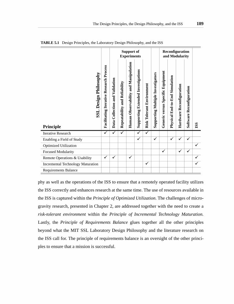
The Design Principles, the Design Philosophy, and the ISS 189
phy as well as the operations of the ISS to ensure that a remotely operated facility utilizes
the ISS correctly and enhances research at the same time. The use of resources available in
the ISS is captured within the Principle of Optimized Utilization. The challenges of micro-
gravity research, presented in Chapter 2, are addressed together with the need to create a
risk-tolerant environment within the Principle of Incremental Technology Maturation.
Lastly, the Principle of Requirements Balance glues together all the other principles
beyond what the MIT SSL Laboratory Design Philosophy and the literature research on
the ISS call for. The principle of requirements balance is an oversight of the other princi-
ples to ensure that a mission is successful.
TABLE 5.1 Design Principles, the Laboratory Design Philosophy, and the ISS
Support of Experiments
Reconfiguration and Modularity
Principle
SSL
Des
ign
Philo
soph
yFa
cilit
atin
g It
erat
ive
Res
earc
h Pr
oces
s
Dat
a C
olle
ctio
n an
d Va
lidat
ion
Rep
eata
bilit
y an
d R
elia
bilit
y
Hum
an O
bser
vabi
lity
and
Man
ipul
atio
n
Supp
ortin
g E
xten
ded
Inve
stig
atio
ns
Ris
k To
lera
nt E
nvir
onm
ent
Supp
ortin
g M
ultip
le In
vest
igat
ors
Gen
eric
ver
sus S
peci
fic E
quip
men
t
Phys
ical
End
-to-
End
Sim
ulat
ion
Har
dwar
e R
econ
figur
atio
n
Soft
war
e R
econ
figur
atio
n
ISS
Iterative ResearchEnabling a Field of StudyOptimized UtilizationFocused ModularityRemote Operations & UsabilityIncremental Technology MaturationRequirements Balance

190 MICROGRAVITY LABORATORY DESIGN PRINCIPLES
5.9 Science in the ISS to Date: Applicability of the Principles
This section reviews the science conducted aboard the ISS so far to identify common
designs and operations implementations to identify if the principles presented in this thesis
are exhibited in past experiments, even if not specifically designed to do so. The existence
of the traits of the principles in past experiments provide insight into how the principles
should be applied to future experiments.
The ISS is currently hosting the crew of Expedition 10. Expeditions 1-7 consisted of three
crew members; expeditions 8-10 have two crew members. The smaller crew on the later
expeditions has limited the ability to conduct science aboard the ISS, therefore it is more
relevant to study the science conducting during a 'full' expedition. Expedition 6, which
was the last expedition to operate with a standard crew of three and performed the
expected number of experiments that will take place in the long-term, has been fully
researched. Table 5.2 shows all the experiments in Expedition 6. The NASA White Papers
[NASA, URL1] about each experiment were reviewed to understand the design and oper-
ations of each project. The white papers provide sufficient information to identify the gen-
eral characteristics of the experiments and determine whether the design follows a specific
principle. These reviews do not evaluate the experiments, the reviews identify if past
experiments exhibit the characteristics of a principle to determine the applicability of the
principles.1
The Expedition 6 results demonstrate some important trends related to the principles. As
Chapter 2 explains, the thesis concentrates on iterative space technology maturation
experiments. Expedition 6 conducted 21 different experiments: ten in the bioastronautics
area, six in the physical sciences, two in space product development, and three in space
flight technologies. Out of the ten bioastronautics experiments, six are exposure experi-
1. The Principle of Requirements Balance is not used in this review since the deployment of the project aboard the ISS implies the mission successfully met its principal requirements. Further, the basic infor-mation presented in the white papers does not provide enough insight to determine specific requirements of a mission.

Science in the ISS to Date: Applicability of the Principles 191
TABLE 5.2 Experiments in Expedition 6Id Field Experiment Rep
eat
Size
Iter
ativ
e
Fiel
d
Util
izat
ion
Mod
ular
ity
Usa
bilit
y
Mat
urat
ion
1 Bioastronautics Research
The Effects of EVA on Long-term Exposure to Micro-gravity on Pulmonary Function (PuFF)
M
2 Renal Stone Risk During Space Flight: Assessment and Countermeasure Validation (Renal Stone)
M
3 Study of Radiation Doses Experienced by Astronauts in EVA (EVARM)
M
4 Subregional Assessment of Bone Loss in the Axial Skele-ton in Long-term Space Flight (Subregional Bone)
S Only Pre/Post flight
5 Effect of Prolonged Spaceflight on Human Skeletal Mus-cle (Biopsy)
S Only Pre/Post flight
6 Promoting Sensorimotor Response Generalizability: A Countermeasure to Mitigate Locomotor Dysfunction After Long-duration Space Flight (Mobility)
S Only Pre/Post flight
7 Spaceflight-induced Reactivation of Latent Epstein-Barr Virus (Epstein-Barr)
S Only Pre/Post flight
8 Entry Monitoring DELAYED
9 Chromosomal Aberrations in Blood Lymphocytes of Astronauts (Chromosome)
S Only Pre/Post flight
10 Foot/Ground Reaction Forces During Space Flight (Foot) L
11 PhysicalSciences
Protein Crystal Growth-Single-locker Thermal Enclosure System (PCG-STES)
L
12 Microgravity Acceleration Measurement System (MAMS)
M
13 Space Acceleration Measurement System II (SAMS-II) M
14 Investigating the Structure of Paramagnetic Aggregates from Colloidal Emulsions for the Microgravity Sciences Glovebox (MSG-InSPACE)
L
15 Vibration Isolation System for the Microgravity Sciences Glovebox (MSG-g-LIMIT)
M No data
16 Coarsening in Solid-Liquid Mixtures for the Microgravity Science Glovebox (MSG-CSLM)
M
17 Space Product Development
Zeolite Crystal Growth Furnace (ZCG) L
18 Microencapsulation Electrostatic Processing System (MEPS)
L
19 Space Flight Crew Earth Observations (CEO) S
20 Earth Knowledge Acquired by Middle-School Students (EarthKAM)
S
21 Materials International Space Station Experiment (MISSE)
L

192 MICROGRAVITY LABORATORY DESIGN PRINCIPLES
ments (one was delayed), and the principles do not apply to them, as they do not create the
facilities to implement a laboratory, but rather only use the fact that humans are exposed to
the microgravity environment. Of the remaining four experiments, three exhibit the char-
acteristics of the optimal utilization and operations and usability principle. The last exper-
iment (PuFF) makes use of modularity.
The six physical science experiments are more evenly divided in the use of the principles.
Two experiments (PCG-STES and MSG-InSPACE) exhibit many characteristics of the
principles. It is interesting to see that these two experiments are the only ones that clearly
exhibit the ability to perform iterations aboard the ISS. The experiments provide the nec-
essary facilities for astronauts to repeat experiments in a manner that advances the itera-
tive research process. While MSG-InSPACE appears limited in scope, PCG-STES
provides research facilities for a large number of scientists to conduct a wide range of pro-
tein crystal growth experiments. Further, PCG-STES exhibits modularity. Both experi-
ments utilize the resources available on the ISS to simplify the design of their facilities
and enhance their capabilities by utilizing the astronaut time efficiently.
On the other hand, several physical sciences experiments on this expedition were effec-
tively exposure experiments. The MAMS and SAMS-II experiments simply collect data
for analysis later on. They do not exhibit any of the characteristics of the principles.
Space product development shows a growing trend toward exhibiting the characteristics
of the design principles. One experiment, ZCG, exhibits a large number of the principles,
only lacking enabling iterative research (while the utilization does not appear optimized,
since it appears that the experiment could benefit from further crew time utilization and
better interfaces, it correctly uses the standard ISS experiment rack supplies). The MEPS
experiment also lacks the ability to enable the iterative research process, and it seems it
would benefit strongly from better use of the ISS resources. But, the experiment does pro-
vide modular facilities for multiple researchers and has been designed to operate remotely
with ease.

Science in the ISS to Date: Applicability of the Principles 193
The space flight experiments of Expedition 6 consisted of an observation experiment
(CEO), an educational experiment (EarthKAM), and an space technology research experi-
ment (MISSE). The first two experiments do not exhibit a substantial number of character-
istics from the principles. MISSE, on the other hand, exhibits several characteristics of the
principles. MISSE is an exposure experiment, in that its samples are located outside the
ISS and left unattended for an extended period of time; therefore, MISSE does not enable
iterative research. But the facilities of MISSE do provide a modular setup where a large
number of scientists can study a substantial amount of materials science. Further, the
design directly accounts for several of the resources of the ISS: power, benign environ-
ment (exposed), and long-term experimentation. MISSE even accounts for the use of crew
time since the exposed facility is designed to be accessed by EVA in case changes are
needed. Lastly, MISSE was designed to allow cheap access to the space environment to
better understand material science, effectively creating a facility to enable incremental
technology maturation for space materials.
A trend identified in the operational description of a majority of these projects is that
many researchers are proud that their facilities practically do not use crew time. In many
cases the crew simply turns the experiment on and does not interact with it again until
samples or data must be returned to the scientists. The extremely limited crew time has
clearly pushed experiments to operate autonomously, and the fact that a human is present
in the operational environment has not been utilized correctly. As a consequence of requir-
ing autonomous experiments due to limited crew time, all these autonomous experiments
do not enable iterative research aboard the station. Rather, the experiment provides data
for one iteration; subsequent operations require delivery of further hardware to or from
ground and direct interaction of the scientist.
The experiments of Expedition 6 confirm the stated intent of the principles: to guide in the
development of iterative space technology maturation experiments. The review of the
experiments clearly indicates that the principles do not apply to observation or education.
On the other hand, the experiments of Expedition 6 which required multiple samples, a

194 MICROGRAVITY LABORATORY DESIGN PRINCIPLES
wide range of scientists, or interfaces with the crew exhibited the characteristics of a large
number of the principles. Further, it is interesting to note that these experiments are physi-
cally and operationally large compared to the other experiments; the need to provide the
necessary facilities requires the experiment to utilize more space.
Past experiments of the ISS show that the principles presented in this chapter are applica-
ble to space technology maturation experiments conducted aboard the ISS. While not all
of the experiments conducted aboard the ISS will benefit directly from these principles, it
is clear that a substantial portion of the larger experiments conducted aboard the ISS will.
Therefore, a researcher who identifies a new technology need requires clear and concise
guidelines on how to apply these principles to achieve technology maturation. The next
section presents a design framework to aid scientists in following these design principles.
5.10 Design Framework
The design framework concentrates on allowing a research scientist to design a laboratory,
with its necessary ISS and ground based facilities, that meets the principles. The frame-
work consists of several design steps which sequentially detail the requirements of the
facilities that comprise the laboratory. The framework also provides general guidelines to
evaluate if a specific design principle is being satisfied by the laboratory and determine
whether there are benefits towards the maturation of the space technology by operating
aboard the International Space Station. Through this framework the scientists can intro-
duce their perspective of the science goals as well as the constraints of the project.
The application of the principles onto a new design does not occur in parallel for all the
principles. As explained in the Principle of Requirements Balance, the design process is
itself iterative, and therefore composed of several steps. With this in mind, the strategy
presented in Figure 5.3 was developed. The figure groups the principles into the following
main actions: determination of mission objective, identification of a field of study, initial
design of a facility, identification of modular elements and design of operational elements,
and balancing of the requirements. The application of each principle has been ordered so

Design Framework 195
at to create an incremental set of requirements for the design of the facility. The order
should help refine the requirements at every step. These actions are iterated until a final
design is achieved.
The mission objective is determined by the customer. These objectives determine the sci-
ence requirements of the mission. To satisfy these requirements, a laboratory must usually
demonstrate results which cover a large area of study and which compare several designs
to identify the best solution. The design principles of this thesis provide benefits when the
research scientist charged with the mission determines that technology maturation is nec-
essary and believes that the mission may benefit from operating in the ISS. In that case,
the following steps should be taken to create a facility which will benefit from being in the
ISS and which will facilitate the maturation of the space technology:
Step 1 - Identify a Field of Study
• Principle of Enabling a Field of Study
Figure 5.3 Design principles application strategy
MissionObjective
Principle ofEnabling a
Field of Study
Principle ofIterativeResearch
Principle ofOptimizedUtilization
Principle ofFocused
Modularity
Principle ofRequirements
Balance
Principle ofRemote
Operation
Principle ofTechnologyMaturation
LaboratoryDesign
1 2 3 4
196 MICROGRAVITY LABORATORY DESIGN PRINCIPLES
The first step is to identify the field of study the facility will support. The initial
attempt is to select a large enough area in the field of study that the experiment can
support technology maturation, but not so large that it is impossible to identify a
clear set of science requirements.
Step 2 - Identify Main Functional Requirements
• Principle of Iterative Research
• Principle of Optimized Utilization
• Principle of Technology Maturation
The next step combines three principles that allow identification of the main func-
tional requirements for the facility.
The principle of iterative research sets several requirements for the facility. Through
this principle the scientist can determine the need for inputs and outputs, data cap-
ture and transfer rates, and requirements on the repeatability and reliability of the
system. The principle also calls for the scientist to set requirements on the schedul-
ing of experiment sessions and needs for data analysis.
The principle of optimized utilization provides an essential piece of information:
should this facility be part of the ISS program or not? The principle requires the sci-
entist to study the reasons for operating in the ISS and how the resources made
available by the ISS are being used by the facility. It also gives the scientist an idea
of which resources affect the facility heavily and which do not. Once it is deter-
mined which ISS resources should be used, a clear set of interface requirements to
the ISS can be created.
For a facility to achieve technology maturation it must provide a representative
environment for assembled sub-systems and/or prototypes. The definition of that
environment and those systems are cast into clear requirements for the facility.

Design Framework 197
After all these requirements have been created it should be possible to identify a
limited set of design options for the facility. These designs will be further studied in
step 3.
Step 3 - Refine Design
• Principle of Focused Modularity
• Principle of Remote Operations and Usability
Step 2 identified all the major requirements for the system to achieve the science
goals and helps create a limited set of candidate designs. Step 3 identifies those
designs that best meet the call for modularity and ensures that the designs meet the
need for remote operations.
As described within the principle of modularity, its goal is not that the initial objec-
tives are for a modular system, but rather to identify those parts of a design that can
be modular. Therefore, the principle of modularity is applied once a set of designs
has been selected to search for those elements of the facility that meet the principle.
The principle of remote operation and usability requires a minimum set of informa-
tion to provide valuable feedback, specifically: knowing what type of data the oper-
ator needs and what processing tools the scientist needs.
Step 4 - Review Requirements and Design
• Principle of Requirements Balance
Once the set of requirements has been finalized and a preliminary design conceived,
the principle of balanced requirements calls for a review of the requirements prior to
going on. At this point the scientist must evaluate whether the proposed facility has
any requirements that have too much effect on the cost of the mission, and if they
should be changed.
If the scientist determines that the requirements should be reviewed, the process
should restart at step one to maintain objectivity. If the scientists agrees with the

198 MICROGRAVITY LABORATORY DESIGN PRINCIPLES
weight of each requirement and determines that the mission objectives will be met,
then the process is finalized.
These steps provide a general overview of the laboratory design process to implement the
design principles. The following sections presents general guidelines to determine func-
tional requirements which satisfy the design principles.
5.10.1 Step 1 - Identify a Field of Study
This step utilizes the Principle of Enabling a Field of Study to determine the breath of the
research. The following section presents guidelines to determine the range of the research
that should be possible to research in a space technology maturation laboratory.
Principle of Enabling a Field of Study
Identifying the field of study and the areas which comprise it is a subjective process con-
ducted by the research scientist to ensure the mission science objectives are fulfilled. The
science objectives sometimes immediately identify the field of study; for example, when
the mission objective is to mature the technology of a specific spacecraft subsystem as
defined by [Larson, 1992]. In this case, the field of study may be propulsion, avionics, or
structures. The research scientist can then identify the areas of study which comprise this
sub-system, and select those areas which the laboratory allows to be studied. Other times,
the mission objectives may not immediately identify the field of study; the mission objec-
tives may be too broad to clearly identify a field of study or too narrow to be considered a
complete field. For example, the mission may call for the observation of stellar objects, in
which case the scientist must determine what part of a spacecraft for space observation
requires technology maturation, and select that part as the field of study. On the other
hand, a mission objective may simply call for the optimization of a specific control algo-
rithm; in those cases the scientist needs to determine if its possible to study a substantial
part of the controls field, rather than concentrate on the single algorithm. If the objective
of the research scientist is to develop a laboratory for space technology maturation, rather

Design Framework 199
than a single facility to test a specific concept, the research scientist must identify the field
of study for the laboratory, even if that differs slightly from the science mission.
Once a field of study has been clearly defined, the subject areas which comprise the field
of study must be identified. Each area must be complimentary to another, rather than rep-
licate efforts on gaining the same type of knowledge. A laboratory allows the study of a
meaningful number of the areas such that, when the knowledge gained from tests in all
areas covered by the laboratory is brought together significant steps are taken to mature
the technology.
The identification of specific areas of study allows the designer to determine if multiple
scientists will need to conduct research in the laboratory in order to cover all the areas.
Determining the need to support multiple scientist is necessary at this point, since the
facilities will have different requirements depending on the number of scientists involved.
Guidelines for these requirements are presented below. If at this point the determination is
made that one scientist can perform all required research, there is a high probability that
the initial field selection was too narrow; specific area of a field of study was selected,
rather than a field of study. The designer should return to the first step and ensure that a
field of study is being covered.
The facilities to support a field of study, researched by multiple scientists, must provide
the following functionalities:
• Allow all scientists to create models of their work in their home locations.
• Create simple interfaces for the scientists to utilize the testing facilities.
• Ensure efficient data transfer between the scientists and the testing facilities.
• Provide flexible operations plans for scientists to conduct experiments.
• Enable software and/or hardware reconfiguration to cover all subject areas.
At this point it is useful to calculate an initial cost of creating the laboratory environment
by using existing guidelines such as those presented in [Larson, 1992] or existing design
tools such as those developed by [Matossian, 1996], [Shaw, 1998], [Mosher, 2000], and

200 MICROGRAVITY LABORATORY DESIGN PRINCIPLES
[Jilla, 2002]. These initial costs can be used to determine the number of areas of study
which should be covered by the laboratory to obtain a benefit by studying a substantial
part of a field, rather than developing individual test facilities for each area of study. The
following equation, based on the methods proposed in [Meyer, 1997] to measure the effi-
ciency of product platforms, provides a general idea of the efficiency of using a laboratory
rather than multiple facilities:
(5.1)
where:
m = total number of areas in the field of study
n = number of areas covered by the laboratory
Klab = cost of the common laboratory facilities
ki = cost of enabling each area of study
Ki = cost of developing an independent facility for each area of study
The numerator considers the costs of implementing derivative products; the numerator
represents the cost of implementing new products every time. The factor relates the
total number of areas of study with the ability of the laboratory to support multiple areas;
as more areas are supported, the factor decreases. The goal is to ensure that the cost J is
less than 1.
Using the guidelines presented in [Larson, 1992] and the experience of the MIT SSL
microgravity projects, it is possible to make the following assumptions:
• The costs Ki will always be larger than the costs ki, since developing com-plete facilities requires substantial launch cost and development of commonequipment.
• The costs ki will not be constant for all ares of study.
J mn----
Klab ki
i =
n
∑+
Ki
i =
n
∑
-------------------------------⋅=
m n⁄

Design Framework 201
• The cost Klab will be larger than the costs Ki, since it requires the addition ofresources to support multiple scientists.
Under these assumptions, the general trends of cost J can be represented graphically, as
shown in Figure 5.4. While the figure shows only a pictorial representation of cost J, it
provides the designer with important information:
• Utilizing this measure, a laboratory must cover multiple areas of study; evenif the cost of a facility is small, not covering multiple areas of study results ina high cost.
• As the cost of supporting areas of study increases, a facility will need to sup-port more areas to result in a cost factor less than 1.
• It is possible that supporting certain areas of study results too high and drivesthe cost beyond the threshold as it is added.
5.10.2 Step 2 - Identify Main Functional Requirements
This step calls for scientists to determine the main functional requirements of the labora-
tory once the field of study has been defined. Three principles are used to determine these
requirements: Principle of Iterative Research, Principle of Optimized Utilization, and
Figure 5.4 General trend of cost J using cost function 5.1
% of field of study covered
Increased costper area of study
0% 25% 50% 75% 100%
Frac
tiona
l cos
t of L
abor
ator
y
1
Expensive area
202 MICROGRAVITY LABORATORY DESIGN PRINCIPLES
Principle of Technology Maturation. The guidelines to determine the functional require-
ments using these principles are presented next.
Principle of Iterative Research
Designing a laboratory to satisfy the Principle of Iterative Research requires that the facil-
ities of the laboratory permit to close at least one of the iterative loops presented in
Figure 5.1 on page 174; preferably, a laboratory which operates aboard the ISS not only
allows repetitions of experiments (loop 1), but also modifications of experiments (loop 2)
and the hypothesis (loop 3). For this to occur, a facility design must exhibit efficient and
sufficient data collection and analysis tools, as well as the ability to reconfigure the facil-
ities with new experiments that reflects the knowledge obtained during previous iterations.
Further, the laboratory needs to develop a flexible operations plan which provides scien-
tists with sufficient and flexible science time.
Data Collection and Analysis Tools
Data collection is part of the overhead time; data analysis is part of science time. The
design of a laboratory should minimize the work to collect data, and ensure that the col-
lected data are of the appropriate quality. At the same time, the laboratory must provide
the correct tools for efficient data analysis to support or refute experiments and hypothe-
sis.
Data collection consists of four main parts: capture bandwidth, precision, accuracy, and
data transfer. For successful data collection, the following guidelines should be met:
• Bandwidth - The data sampling rate indicates the maximum bandwidth ofthe collected data. The facilities must be designed with the maximum band-width possible, so that they can be used for as yet unforeseen research. In nocase should the Nyquist criterion (sample at twice the frequency of the high-est mode of the system which should be observed) not be met for known sys-tem bandwidths; further, as per [Larson, 1992], the sampling factor shouldbe 2.2 to account for model uncertainties.
• Precision - Data precision tells the scientist how small a change in the phys-ical system can be measured. A high precision system can measure small

Design Framework 203
changes; a low precision system can only measure big changes. As a generalguideline, the precision should be a fraction of the "impulse bit" (the small-est actuation possible) of a system, such that the sensors can successfullymeasure the effects of one impulse bit.
• Accuracy - Data accuracy accounts for how close a measurement is to theactual physical event. The higher the accuracy, the closer the measurement isto reality. Because accuracy greatly benefits from in-flight calibration [Lar-son, 1992], the scientist must design a laboratory so that its measurementsystems can be calibrated once operational aboard the ISS. If in-flight cali-bration is not possible, the scientist must account for the physical effects oflaunch and deployment on the ultimate accuracy of the system and ensure itis of good enough quality for successful research.
• Transfer - Once captured, that data must reach the scientist. Data transferdoes not necessarily need to be in real-time in order to meet this criteria,although real-time data could benefit experiments. But the transfer timesmust not substantially affect the available science time; data transfer timesshould never be a substantial fraction of data analysis time. Therefore, afacility must interface correctly to available communications resources tominimize the data transfer time.
Once the data reaches the scientist they must be analyzed. A complete laboratory provides
scientists with data analysis tools which minimize the time between receiving the data and
the start of analysis. It is not sufficient to make the data available to the scientist, they
must be able to use it efficiently. For this, the laboratory must clearly define the type of
data transferred to the scientist and the format in which the data is transferred. Further,
tools to convert the data into those formats which best suit the needs of the scientist must
be created before experiments are conducted, so that data analysis time is spent in examin-
ing the data, rather than in making the data available and presentable in the correct format.
Enable reconfiguration
In designing a laboratory which facilitates the iterative design process, it is necessary to
determine the level of reconfiguration necessary to close each of the three iterative loops
presented in Figure 5.1. The design process should include the identification of what is
needed to close each of the three loops, and subsequently, based on the resources available

204 MICROGRAVITY LABORATORY DESIGN PRINCIPLES
for the project, determine which loop is to be closed. The following points serve as guide-
lines to determine what is required to close each of the loops:
• Repeat Experiments
- Ensure the operator’s interfaces permit starting tests with minimal over-head from repetitive tasks.
- Facilitate the repetition and/or measurement of initial conditions.
- Enable resupply of consumables.
- Provide sufficient space for data storage.
• Modify Experiments
- Enable initial conditions to change sufficiently for the difference betweenexperiments to be relevant.
- Allow scientists to specify a different set of variables for the system, be itvia hardware or software changes, consistent with DOE techniques([Fisher, 1935],[Mead, 1988],[Antony, 2003]).
- Allow changes in the response of the system to the same actuation by theaddition or removal of hardware or software
• Modify the Hypothesis
- Allow for the modification of both sensors and actuators so that differenttypes of data are available as research progresses.
- Ensure that new models of the problem are supported by the facilities thatsupport the operator and the researcher.
The facilities aboard the ISS must allow any software or hardwarewhich utilizes models of the problem to be fully reconfigured.
The data analysis tools of the researcher must allow its models to beupdated.
- Provide for the ability to modify the operational plans of the laboratory toaccommodate for the need to develop new facilities; allow these newfacilities to operate under new plans.
The capability of a laboratory to allow modifications must be bound by the limit of the
available resources. For example, if a program only calls for one launch to the ISS, then it
is not possible to claim that the system can be fully reconfigured by a second launch;
reconfiguration must be enabled in the original facility. On the other hand, if a program
has secured several flights to the ISS, it can utilize those to modify the facilities suffi-

Design Framework 205
ciently to enable modification of the hypothesis without having to implement more com-
plex features in the original hardware.
Flexible Operations Plan
Enabling data collection and reconfiguration features in a laboratory does not guarantee
successful iterative research. The iterative research process greatly depends on the avail-
ability of time for the scientist to conduct the necessary research. Therefore, a flexible
operations plan which provides this science time is essential. Figure 5.5 illustrates this
concept. The experience from MODE, DLS, and MACE has shown that too short or too
long a time between iterations has a negative effect on the iterative research process. This
concept is captured in the bottom plot. On the other hand, an experiment quickly benefits
as iterations start; but the benefits from each iteration decreases each time; ultimately, the
benefit asymptotes as the number of iterations increases. This concept is illustrated in the
left side plot. The center plot shows that there exists a middle area where both the time
between iterations and the number of iterations provide substantial benefits to the science.
The goal is to design all laboratories to allow iterations in this area.
Figure 5.5 Achieving effective iterations though flexible scheduling.
good
bad
good ba
d
MACE
MACE-II
DLS
EffectiveIterativeResearch
IneffectiveIterativeResearch
ShuttleISS
MIR
RGA
Time between iterations τi
Num
ber o
f ite
ratio
ns
MODE-Reflight
0n
>> 1
short long

206 MICROGRAVITY LABORATORY DESIGN PRINCIPLES
Reduced gravity airplanes (RGA) provide very short time periods between iterations, only
allowing the capture of data. MACE, MODE, and MODE-Reflight all operated aboard the
Space Shuttle, which provides only short periods to analyze data and iterate. MODE-
Reflight is shown twice, since the second flight was effectively a single iteration of the
first flight, since lessons were learned, but the time between the two flights was exceed-
ingly long. MACE-II operated aboard the ISS for an extended period of time, but the lack
of communications at the time prevented a significant number of iterations to take place.
DLS, which operated aboard MIR, was close to operating in an effective region of the iter-
ative research process, but the long delays in communications between the researchers,
NASA, and their Russian counterparts proved to have some negative effect on the
research.
Figure 5.5 does not indicate quantitative figures for the actual time between iterations or
the number of iterations that must be accomplished. Each scientist must determine the
quantitative values for their specific research projects, since they can vary widely. The fol-
lowing guidelines should be followed in determining these values:
• An iteration consists of all the actions between conducting an experiment,collecting the data, achieving scientific knowledge, and applying that knowl-edge to mature a technology. An iteration is not the time it takes an operatorto repeat an experiment; it includes all the steps to conduct the experiment,analyze the data, and determine the next step to take.
• Do not force the time between iterations, τi, to be fixed; find a minimum andmaximum time between iterations which provides enough flexibility to theresearch scientist.
- The minimum time between iterations must account for the need to ana-lyze data and upload, at least, new experiments.
- The maximum time between iterations must account for the resourcesavailable to the program. Also, it must account for other research whichcould reduce the value or replace the research of the laboratory.
- Increasing the number of scientists using the laboratory enables the cre-ation of a fixed time between iterations, as it increases the possibility thatany one scientist will make use of the facilities when available, even if theothers need further analysis time.

Design Framework 207
• It is beneficial to maximize the number of iterations which can be executedin the laboratory, especially if multiple scientists are involved in theresearch.
Principle of Optimized Utilization
A primary goal of the principle of Optimized Utilization is to change the way in which
people think of the resources available in the International Space Station. The review of
ISS experiments presented in Section 5.9 indicates that the majority of projects currently
consider the cost of utilizing a resources; the design of existing facilities attempts to mini-
mize the cost by reducing the use of resources. While in general this is a common goal of
space missions, the use of the ISS should not follow those standards. ISS resources pro-
vide value to missions, and the correct use of these resources should maximize the value
obtained by the project from using the correct resources for the specific science goals.
Therefore, the development of a laboratory must consider all the resources available and
optimize their use with respect to the research needs.
The first step in designing a laboratory which correctly utilizes the resources available
aboard the ISS is to understand the resources and select those that are useful to the
research:
• Understand the resources and limitations of the ISS. [NASA, 1998] and[NASA, 2000b] provide substantial information on the resources availablefor research aboard the ISS; the finding from these references are summa-rized in Chapter 2.
• Determine the needs of the research. Based on the mission objectives andthe other principles, the designer can determine the general operational pro-cesses of the facilities which will operate aboard the ISS and at MissionControl. The general operations provide insight into which resources benefitthe mission.
• Realize which resources do not provide a benefit to the research. While thegoal is to maximize the value obtained from the resources aboard the ISS,there may be cases in which utilizing a resource presents more challengesthan benefits to the science. If a resource cannot provide positive value to themission, the scientist must realize this early in the design process, and decidenot to use that resource.
208 MICROGRAVITY LABORATORY DESIGN PRINCIPLES
A set of guidelines based on value models presented in [Cook, 1997] was developed to
help better understand the availability of resources aboard the ISS. The value curves pre-
sented in [Cook, 1997] utilize Taguchi functions which consist of Nominal is Better
(NIB), Larger is Best (LIB), and Smaller is Best (SIB) models. The original Taguchi NIB
functions are centered around a central value (the curves are symmetrical about the best
value), which is not necessarily the case for the ISS resources. Therefore, these functions
have been adapted to generate value curves which better represent the availability of
resources aboard the station.
The Taguchi method normalizes the value obtained from a resource between 0 (least
value) and 1 (most value). The parameters which define the shape of the value curves rep-
resent the availability of the ISS resources identified in Chapter 2 based on the informa-
tion provided in [Hagopian, 1998], [NASA, 1998], [NASA, 2000b], [NRC, 2000] and
[Durham, 2004]. The curves represent the ability of the ISS to provide that resource; if the
resource can benefit the laboratory, then the amount of resource to utilize should be con-
sistent with the value curve.
Table 5.3 summarizes the findings of the availability of the special ISS resources and
Figure 5.6 presents the resulting value curves. The table indicates the type of modified
Taguchi value curve used for each resource (NIB, LIB, or SIB); in one case a value curve
is not appropriate, and Yes/No (Y/N) values are recommended. The base value indicates a
starting value for the design. The critical value represents the point at which the ISS can
no longer provide that resource, and further usage would negatively affect other research
operations aboard the station; therefore, experiments should not use these amounts of
resources. The ideal column indicates the point at which the ISS resources can be best
shared among research facilities. The determination of these values was based on the fol-
lowing information about each resource:
• Crew - Human presence is one of the most important characteristics thatseparate ISS operations from standalone spacecraft. Therefore, the value ofthis resource is based on a nominal is better (NIB) curve - the astronauts

Design Framework 209
should perform tasks for the experiment, but only for a limited time. Theparameters were obtained as follows:
- The review of Expedition 6, with three astronauts aboard the ISS, pro-vided a total of 2160 hours per month of astronaut time. According toNASA approximately 10% of astronaut time can be used for scienceexperiments Therefore there are a total of 216 hours per month availablefor science. Review of ISS science up to date reveals that there areapproximately a dozen experiments in the ISS at any one time, leavingapproximately 18 hours per experiment per month as an ideal value
The recommended NIB value curve drops sharply as less than eight hoursper month of astronaut time are used, since it results in a waste of an impor-tant resource of the ISS. If more than 50 hours per month are used, the facil-ity starts to reduce the available resources to other projects, also reducing itsvalue.
• Power sources - The value of the ISS with respect to power is presentedusing two measures:
- Minimize total power. The curve for absolute power utilization is asmaller-is-better (SIB) curve since the total power consumed should beminimized. The ISS will provide up to 46kW of electrical power; eachlocker provides an average of 2kW of power, making that the ideal value.The base value of 4kW is based on an average of 12 experiments presentin the station at any one point. The critical value of 20kW is based on themaximum available power using special resources.
- Maximize power fraction used from ISS. This is a larger-is-better (LIB)measure - a facility should maximize the percentage of power used fromthe ISS with respect to the total facility power.
• Telemetry upload/download - The ISS communications system value isbased on the NIB value curve. The available data bandwidth is 1.5Mbps,with expected upgrades to 15Mbps in the next couple of years. Given that
TABLE 5.3 Summary of ISS special resources
Resource Type Unit Base Critical IdealCrew NIB hours/month 10 144 18Power Sources - usage SIB kW 4 20 2 - percentage LIB % 50 0 100Telemetry NIB Kbps 7 1000 100Duration NIB months 6 120 6Benign Env’t / Atmosphere Y/N - [1 0] - -

210 MICROGRAVITY LABORATORY DESIGN PRINCIPLES
there are approximately a dozen experiments in the ISS, the current idealvalue is for each project to use approximately 100Kbps of bandwidth onaverage.
• Long-term experimentation - The parameters for long term experimenta-tion take into account the presence of astronauts in a schedule of every sixmonths and an ISS life expectancy of 15 years. An NIB curve is recom-mended for long-term experimentation. The ideal value for the longevity ofan experiment is one expedition (six months), due to training and other oper-ational constraints. The other limit is the station's life expectancy of approxi-
Figure 5.6 Value curves for ISS unique resources
0 50 100 1500
.5
1
crew time [h/month]
0 2 4 6 8 10 12 14 16 18 200
.5
1
total power [kW]
0 10 20 30 40 50 60 70 80 90 1000
.5
1
% ISS power [%]
0 100 200 300 400 500 600 700 800 900 10000
.5
1
telemtry bandwidth [kbps]
0 20 40 60 80 100 1200
.5
1
lifetime [months]

Design Framework 211
mately 10 years from now. The value between six months and several yearsof operation is almost the same, since the limitations from the ISS perspec-tive lie solely on astronaut training and availability. The value drops forshorter periods, since the expenses in the deployment of a project to the ISSshould be amortized over longer operations. The value curve is not an LIBbecause experiments that reside too long in the ISS restrict the availability ofresources, preventing other facilities from operating and limiting the scienceconducted aboard the station.
• Benign Environment / Atmosphere - The value of utilizing the benignenvironment of the ISS does not follow a Continuos curve; rather, it is abinary yes/no determination. A scientist should consider the following pointsto ensure the laboratory’s facilities benefit from this resource:
- The monitoring capabilities of the ISS should be utilized to safeguard thefacilities aboard the station.
- Astronauts should be able to prevent and/or repair damage to a facility toensure long-term operations.
- Facilities aboard the ISS should utilize the standard interfaces of the ISSavailable for research, including the availability of structural mountingpoints, supply lines, and data connections.
- Facilities which operate inside the ISS should reduce their cost by utiliz-ing standard components without special treatments to account for thespace environment.
Principle of Incremental Technology Maturation
The achievement of technology maturation in an experimental setup suggests that the
operational environment of the experiment resembles the final application enough so that
the technology is considered reliable for operations in the next level of technology readi-
ness. Therefore, in order to determine how well a design meets this principle, one must
examine how far into the TRLs we can go using this facility and how much the cost and
risk can be reduced by developing technologies in the ISS.
To measure how far into the TRLs a technology can be advanced, we use the tests for each
TRLs that apply to operations in the ISS: TRL 5, TRL 6, and TRL 7. An ISS experiment
should provide advancement at least to TRL 5, preferably TRL 6. Some facilities may
even provide TRL 7 advancements if the final technology is compatible with the ISS envi-

212 MICROGRAVITY LABORATORY DESIGN PRINCIPLES
ronment. To measure how far into the TRL's a technology can be advanced, we use the
established tests for each TRL [Lindensmith, 2003]:
TRL 5:
1. The "relevant environment" is fully defined.
2. The technology advance has been tested in its "relevant environment"throughout a range of operating points that represents the full range of oper-ating points similar to those to which the technology advance would beexposed during qualification testing for an operational mission.
3. Analytical models of the technology advance replicate the performance ofthe technology advance operating in the "relevant environment"
4. Analytical predictions of the performance of the technology advance in aprototype or flight-like configuration have been made.
TRL 6:
1. The technology advance is incorporated in an operational model or proto-type similar to the packaging and design needed for use on an operationalspacecraft.
2. The system/subsystem model or prototype has been tested in its "relevantenvironment" throughout a range of operating points that represents the fullrange of operating points similar to those to which the technology advancewould be exposed during qualification testing for an operational mission.
3. Analytical models of the function and performance of the system/subsystemmodel or prototype, throughout its operating region, in its most stressfulenvironment, have been validated empirically.
4. The focus of testing and modeling has shifted from understanding the func-tion and performance of the technology advance to examining the effect ofpackaging and design for flight and the effect of interfaces on that functionand performance in its most stressful environment.
TRL 7:
TRL 7 requires both an actual system prototype and its demonstration in a space
environment. The prototype should be at the same scale as the planned operational
system and its operation must take place in space.
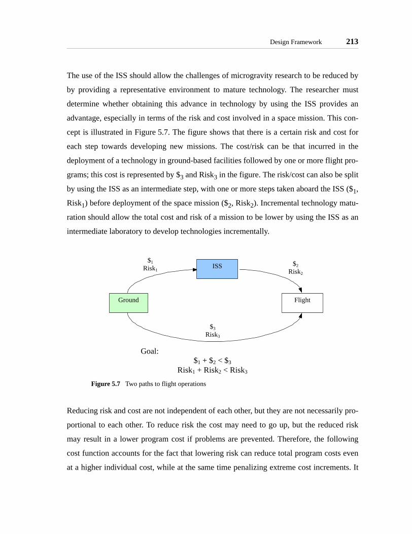
Design Framework 213
The use of the ISS should allow the challenges of microgravity research to be reduced by
by providing a representative environment to mature technology. The researcher must
determine whether obtaining this advance in technology by using the ISS provides an
advantage, especially in terms of the risk and cost involved in a space mission. This con-
cept is illustrated in Figure 5.7. The figure shows that there is a certain risk and cost for
each step towards developing new missions. The cost/risk can be that incurred in the
deployment of a technology in ground-based facilities followed by one or more flight pro-
grams; this cost is represented by $3 and Risk3 in the figure. The risk/cost can also be split
by using the ISS as an intermediate step, with one or more steps taken aboard the ISS ($1,
Risk1) before deployment of the space mission ($2, Risk2). Incremental technology matu-
ration should allow the total cost and risk of a mission to be lower by using the ISS as an
intermediate laboratory to develop technologies incrementally.
Reducing risk and cost are not independent of each other, but they are not necessarily pro-
portional to each other. To reduce risk the cost may need to go up, but the reduced risk
may result in a lower program cost if problems are prevented. Therefore, the following
cost function accounts for the fact that lowering risk can reduce total program costs even
at a higher individual cost, while at the same time penalizing extreme cost increments. It
Figure 5.7 Two paths to flight operations
$1Risk1
$2Risk2
$3Risk3
Goal:$1 + $2 < $3
Risk1 + Risk2 < Risk3
Ground
ISS
Flight

214 MICROGRAVITY LABORATORY DESIGN PRINCIPLES
quantifies the risk of a mission in terms of the cost of mission failure, the probability of
failure, and weigh it by the possible advances from the mission in terms of TRL levels:
(5.2)
where
$TRL = cost of the facility to allow a specific TRL advance
ρ = probability of failure of the mission such that a TRL advance could no
longer take place (if a facility allows multiple TRL advances, each of
them should be considered independently)
w(TRL#) = the weight assigned to the TRL numbers 5, 6, or 7. Achieving each TRL
brings the technology closer to maturation at different levels, therefore
the weight accounts for the level of technology advancement:
w(5) = 1
w(6) =1.5
w(7) =3
The resulting "risk" is presented in units of cost, such that it can be combined easily with
the total cost of the mission to determine the cost/risk value for a step:
(5.3)
where
$= total cost of the facility
R = total risk/cost of the facility
If a laboratory allows maturation of a technology for multiple TRL’s, the cost of achieving
each level should be accounted independently, and then the total cost added together. For
example, if a laboratory allows a technology to mature through both TRL 5 and 6, then its
total cost should have two parts: first, the cost to deploy the laboratory for operations
R$TRL ρ⋅
w TRL#( )----------------------=
J $ R,( ) $ $ R+$ R–-------------⎝ ⎠
⎛ ⎞⋅=

Design Framework 215
aboard the ISS and costs related to achieving TRL 5; second, the operational costs (with-
out deployment costs, such as launch, if none are incurred) for achieving TRL 6.
5.10.3 Step 3 - Refine Design
Once the primary functional requirements of the system are defined in Step 2, Step 3 iden-
tifies possibilities to get added value from the laboratory’s facilities by providing guide-
lines to decide on the level of modularity in the design and ensure that remote operations
take place efficiently. The principles of Focused Modularity and Remote Operations &
Usability apply in this step.
Principle of Focused Modularity
The Principle of Focused Modularity calls for the identification of parts of a facility which
are generic equipment that could be utilized by other facilities with similar needs. Of out-
most importance in the application of this principle is to remember that the creation of a
modular system must not deviate the project from its original mission objective. Modular
systems must be identified after the initial design of the facility has been created to meet
the science goals of the mission, not designed a-priori as part of the mission objectives.
In some sense it is obvious whether a system is modular or not; a modular system has mul-
tiple components that can be interchanged to create different configurations. The follow-
ing criteria, helps to further identify the applicability of modularity to parts of the system;
it also helps in the design process, to ensure that modularity is thought off as an integral
part of the system while ensuring that the science goals are met:
• Inter-disciplinary use - if the component can be used in different disci-plines within the field it should be generic equipment
• Reconfiguration - if the component easily allows the experiment to changethe general area of study of the experiment, while supporting all other func-tions, it should be generic equipment
• Obsolescence - only those components that are not expected to be obsoleteby the time of re-use should be made generic

216 MICROGRAVITY LABORATORY DESIGN PRINCIPLES
• Life-time - only those components whose life-time is over the anticipatedtime to re-use should be made generic
• Cost amortization - if the component cost is likely to be amortized byfuture use in different experiments it should be generic equipment
• Maintain original goals - the immediate research should not be compro-mised by making a specific equipment generic
The goal of the criteria helps to ensure that the component will not change the original
goals, not be obsolete, and will be fully functional at the time of re-use. Further, it guides
towards the ability of generic equipment to add value to the facility by ensuring the com-
ponent will expand the functionality of the system. Table 5.4 presents a truth table that
indicates whether equipment should be generic or not: based on this criteria.
Principle of Remote Operation and Usability
A successful laboratory exhibits the following characteristics to support both operators
and research scientists by creating the necessary facilities both at the ISS and the ground-
based location of the scientists:
TABLE 5.4 Modularity criteria truth table
Inte
r-di
scip
line
Rec
onfig
ure
Obs
olet
e
Life
-lim
ited
Cos
t Am
ortiz
e
Ori
gina
l Goa
ls
Make Modularx x x x x 0 0x x 0 x x x 0x x x 0 x x 01 x 1 1 x 1 1x 1 1 1 x 1 1x x 1 1 1 1 1
Key: 0 = no, the criteria is not met1 = yes, the criteria is metx = irrelevant

Design Framework 217
• Operators
- Provides the operator with the necessary controls to conduct research effi-ciently
Available controls must ensure the operator can actuate or commandthe facility in every way necessary to perform the experiments
Extraneous controls should not be present to minimize the distractionsof the operator.
Repetitive tasks not directly related to conducting experiments andobtaining relevant data should be minimized.
The controls must meet the requirements for interfaces as defined bythe ISS boards and to account for human abilities. The controls mustconsider the user of tools such as quickening, predictors, and virtualdisplays in the case where the operator must perform real-time maneu-vers or commands.
The operator must always feel safe to stop an experiment.
- Ensures that the data is safely transferred to the scientists regardless ofoperator actions.
A clear data-path must be defined prior to operations so that data is notlost or delayed inadvertently
- Presents relevant information to the operator for successful run of experi-ments.
Allows operators to conduct full cycles of the inner-most iterativeresearch process loop presented in Figure 5.1: they can repeat experi-ments to obtain substantial data without the intervention of the scien-tists.
Provides the operator with enough information to make decisionsabout the course of the experiment while minimizing the risk to theresearch.
Reduces the dependency of real-time audio/video contact between thescientist and the operator.
Presents only the necessary information for the successful run ofexperiments, but does not burden the operator with data not essentialto the conduction of experiments.
- Enables operators to provide feedback to the research scientists from theirobservations in the operational environment.
- Provides methods to conduct real-time communications with the researchscientists under pre-specified circumstances.

218 MICROGRAVITY LABORATORY DESIGN PRINCIPLES
Does not require real-time communications under standard operatingconditions.
• Research Scientists
- Minimizes the efforts and time to collect the data obtained in the remoteenvironment.
The scientist(s) must know in advance the expected delays to obtainthe data
The structure of the data must be fully documented to allow for quickdata parsing when the data is received
Data can be separated into two levels of importance; this fact must beespecially considered if the experiment requires a high amount of data
Critical data needed to continue experiments after one set of opera-tions must reach the scientist efficiently and in a short period ascompared to the iteration period
Support data that is not essential for continued operations can betransferred in a slower fashion
Provides data management tools to extract the data relevant to the sci-entist with minimal overhead.
- Allows scientists to upload information and data to the operator
The scientists must be able to contact the operator to ensure correctoperations of the facilities aboard the ISS.
After reviewing the data and modifying their hypothesis, the scientistsmust have efficient interfaces to upload new experiments to the ISS.
- Provides real-time communications under pre-specific circumstances butdoes not require real-time communications for the scientist to evaluate theprogress of the research.
- Allows scientists to predict results and compare them with the collecteddata.
Ground based facilities should be made readily available to scientistsso that they can predict the results of experiments conducted aboardthe ISS.
These facilities can include simulations, 2D testing environments,and the use of the microgravity testing facilities presented in Chap-ter 1.
The facilities should provide methods to compare predicted results andresults from the data obtained aboard the ISS.

Design Framework 219
Because the interfaces for the operator and the scientist serve a different purpose, there is
no need for both interfaces to be the same; rather, the facility design should consider each
interface separately to meet their specific needs. Further, a laboratory may utilize several
facilities to help the scientist, each with its own interface. (The operator aboard the ISS
should only be required to use on interface.)
5.10.4 Step 4 - Review Requirements and Design
The final step before starting a new iteration (or concluding the functional requirement
identification process) is to ensure that none of the previous steps creates requirements
which drive the system outside of its constraints and/or create conflicts between the prin-
ciples. The Principle of Requirements Balance is utilized in this step.
Principle of Requirements Balance
This principle exists to incorporate two important concepts into the design of a facility
beyond those presented in the previous principles: the need to maintain a missions within
its constraints; and to ensure that no single requirement is driving the design of a labora-
tory, but rather there is a balance in the design. Therefore, this principle necessitates that
the design requirements for the laboratory be specified before it can be applied.
Developing requirements is an iterative process just like any other system design problem,
therefore to meet this principle the scientist is expected to iterate on the requirements of
the other principles and then balance them. The other principles should be evaluated first,
so as to develop a set of basic requirements for the facility. Using the requirements created
from the other principles, this principle calls for the balance of effort into each of the other
principles.
Once the first iteration of a design achieves a clear set of requirements, the first step is to
determine which are hard requirements and which are soft decirements:
• Hard requirements are usually set at the start of a project to ensure that thescience objectives are met. Hard requirements are essential for the success of
220 MICROGRAVITY LABORATORY DESIGN PRINCIPLES
a mission. These requirements are mostly quantitative, and their values sel-dom change after the mission has been defined. When these requirements arequalitative, they clearly define a feature or characteristic that must be presentin the mission for its success.
• Soft 'decirements' are features desired by the scientists but which are notessential to the success of the mission. These requirements can add value tothe mission, but usually due to secondary objectives. Their realization usu-ally occurs after the hard requirements have been set and a scientists seesother possibilities beyond the primary mission objectives. Soft requirementsare not usually quantitative, but rather describe another feature desired in themission. These soft requirements should be treated carefully, as they are theusual source of requirements creep.
Once the requirements have been identified as hard and soft, this principle calls to ensure
that the majority are hard requirements. If the majority of the requirements are soft, then
the scientist must review the design by restarting the design process described in
Figure 5.3 on page 195.
Once a clear set of hard requirements drives the design, one can improve on the measure
of requirements balance by taking into consideration the effort put into meeting each of
the other principles. This effort should be a combination of quantitative facts of the facility
(e.g. cost, personnel, design time, etc.) as well as a subjective evaluation of the scientist
(e.g. expected research value, expected time to maturation, etc.). The scientist should col-
lect as much data as possible on the proposed designs to obtain reasonable expected effort
to satisfy each requirement and assign each requirement a value representative of the
effort.
This principle does not call for all the requirements to be perfectly balanced or to neces-
sarily minimize the soft requirements. A project with balanced requirements will exhibit
limited variations between the efforts to meet each requirement. This principle calls for
the scientist to proactively pursue a realistic justification for each requirement and to
ensure that a substantial part of the effort into the development of the facility goes towards
clearly defined needs.

ISS NGO Evaluation Framework 221
5.11 ISS NGO Evaluation Framework
The call for the creation of a Non-Governmental Organization (NGO) to institutionalize
research aboard the ISS creates a unique scenario in the evaluation of programs that are to
be operated aboard the station. Among the driving principles in the recommendation of the
NRC is that:
"Basic and applied scientific and engineering users should be selected onthe basis of their scientific and technical merit, as determined by peerreview." [NRC, 1999]
Current procedures at NASA separate the safety, training, and funding/selection pro-
cesses; rarely do these processes take into account their effects on the other. The NGO sci-
entists who select projects for the space station are challenged with the need to consider all
parts of a project in its ability to successfully operate aboard the ISS. In order to concen-
trate on the scientific and technical merit of a mission, NGO scientists will need to fully
understand the safety and operational limitations of the ISS. When reviewing a mission
proposal, the technical limitations of the ISS should not immediately be considered some-
thing to prevent a program with high scientific value from taking place. The NGO scien-
tists must care about the success of a mission as something that benefits the ISS.
The design principles provide important guidelines to allow and NGO scientist to deter-
mine the ability of a mission to successfully mature space technologies aboard the ISS. In
arriving to this determination, the NGO scientist will concentrate on the following points:
• Correct utilization of the ISS
• Technology advancement
• Mission probability of success
• Mission scope
The following sections present a framework for the ISS evaluator to use in determining
the correct application of the design principles in a mission design, taking into account
that the evaluator is likely to only have high-level knowledge of the project.1

222 MICROGRAVITY LABORATORY DESIGN PRINCIPLES
Principle of Iterative Research
The evaluation of iterative research must first consider the need for the experiment to
allow iterations aboard the ISS in order for the technology to mature. In some cases a sin-
gle experiment may be all that is needed, and in those case the evaluation should not
penalize the experiment. In the cases where the ISS reviewer determines iterations would
benefit the research, then they must also review the proposed facility to ensure it can con-
duct successful iterations. The ISS evaluator must be able to determine from the proposal
that a facility will allow enough iterations to achieve technology maturation.
The following questions provide the insight necessary to determine if a facility supports
the iterative research process:
1. Does the experiment collect the data necessary to support or refute the
hypothesis?
2. Do the operational plans of the facility provide sufficient flexibility for effi-
cient iterations?
3a. Can the facility perform multiple experiment runs with repeatability and reli-
ability?
3b. Can the facility be reconfigured while in the ISS in such a way to provide
new meaningful results and/or reflect changes in the hypothesis?
A positive answer to the first question is essential since the iterative research process
requires the ability to collect sufficient data to validate or refute the hypothesis. The sec-
ond question requires that the facility operations allow enough time for scientists to exam-
ine the data and present meaningful results. Note that the question does not set a time-
frame for the data analysis, but the requirement that the time exists. The third question
1. The Principle of Requirements Balance is not used by the NGO evaluators. The balance of requirements is directly related to the design of the laboratory; it does not directly affect the effective use of the ISS nor a project’s suitability to operate aboard the station. When a design change occurs due to this process, the research scientist should communicate that to the ISS evaluators when addressing the specific principle where the change occurred.
ISS NGO Evaluation Framework 223
addresses the ability of a laboratory to close at least one of the iterative research loops.
Part 3a is the ability to close the first loop of figure Figure 5.1 on page 174; part 3b
addresses the possibility to close the second and third loops.
Principle of Enabling a Field of Study
The ISS evaluator should be able to readily identify the space technology to be matured
and the selected field of study that the laboratory will cover. It should be clear how
research on that field will directly allow maturation of the space technology. The evaluator
must also be able to identify the specific areas of study which the laboratory enables to be
researched. The areas of study must be complementary to other science already conducted
aboard the space station.
Upon identifying the areas, the evaluator should make their own determination on the
need to support multiple scientists in order for the laboratory to be successful. The deter-
mination of the ISS evaluator should be the same as that proposed by the research scien-
tist, otherwise the proposal should be returned for review.
If multiple scientists are to be supported, then the ISS evaluator must determine the ability
of the laboratory to successfully host them. The proposal should include the development
of facilities both aboard the ISS and ground-based to support the scientists. Specifically,
the ISS evaluator should look for:
• The existence of efficient data paths for the transfer of data to/from the ISSand multiple scientists.
• The ability of scientist to analyze the data in their home facilities.
• Flexible operations plans for scientists to conduct experiments within thelimits of the ISS.
• The need to reconfigure hardware and/or software in the ISS based facilityand the existence of support mechanism to allow said reconfiguration.
The ISS evaluator is concerned with the success of the mission, but must also ensure that a
mission does not create undue burden upon the ISS program by not having the necessary
facilities to support multiple scientists. The research scientist who proposes a mission
224 MICROGRAVITY LABORATORY DESIGN PRINCIPLES
must always provide the means to distribute the data to and from the multiple scientists,
while the ISS staff must ensure the data is readily available to the scientist in charge of the
laboratory. Similarly, the need to change operational plans and reconfigure the facilities
aboard the ISS should be determined by the scientist, and only that scientists should com-
municate the changes to the ISS staff.
Principle of Optimized Utilization
The ISS reviewer should give priority to the use of the special resources of the ISS over
the needs of the project. The research scientists should present their model of the cost/ben-
efit of the resources, allowing the ISS staff to better understand why resources are used (or
not). As the principle prescribes, the goal is to optimize the use of resources, not maximize
them; therefore, a good proposal will clearly define when the use of a unique ISS resource
has a negative effect on the proposal. If a valuable resource is not used at all, but the ISS
evaluator determines the project could make use of that resource, the project should be
sent back for review by the researcher. In the case where very few or none of the special
ISS resources are used by a project, the ISS reviewer may recommend that the project is
better suited for operation as an independent satellite.
Principle of Focused Modularity
The evaluation of modularity from the ISS perspective consists solely on what the project
provides. It should be expected that the scientist already made the trade-off between what
should be modular or not. The ISS staff may identify further modular systems and recom-
mend that the project be re-designed if needed. A modular project should receive higher
priority, especially if its modular items can benefit a large number of scientists in the
future.
Principle of Remote Operation & Usability
The ISS evaluator will concentrate on the operators' point of view. The mission’s ability to
succeed, given the requested data transfer capacities and real-time interaction with the
crew, must also be considered, since the ISS evaluator must care about the success of the

Summary 225
project as well. Therefore, the ISS evaluator must see the following characteristics in the
laboratory:
• The operator has the necessary interfaces to control the facilities aboard theISS in an efficient and safe manner.
• The operator is presented the information necessary to successfully evaluateexperiments.
• The operator can provide feedback to the research scientists from theirobservations in the operational environment.
• A clear data path has been established for the download and upload of data.
• The need for real-time communications has been clearly defined.
Principle of Incremental Technology Maturation
Using the guidelines for the TRL levels, the ISS staff must evaluate the level of the tech-
nology maturation the project provides. Balancing the need for maturation with the other
principles (such as a wide field of study), the ISS reviewer should give priority to those
projects that provide the most technology maturation. The evaluation must take into
account the project's ability to succeed in achieving that level of maturation.
5.12 Summary
The lessons learned in the development of the SPHERES Laboratory for Distributed Sat-
ellite Systems (Chapter 4) following the guidelines of the MIT SSL Laboratory Design
Philosophy (Chapter 3) for use aboard the International Space Station (Chapter 2) resulted
in the development of seven design principles for microgravity laboratories for space tech-
nology maturation. These seven principles are:
• Principle of Iterative Research - enable scientists to conduct iterativeresearch through repetition of experiments to obtain the necessary data tosupport or refute a hypothesis; provide the capability for scientists to analyzethat data and modify their theories on a flexible schedule, and allow recon-figuration of the facilities to allow for changes in experiments and hypothe-sis.
• Principle of Enabling a Field of Study - a laboratory allows research in afield of study, which consists of multiple research areas. To enable the study

226 MICROGRAVITY LABORATORY DESIGN PRINCIPLES
of a field, it is almost always true that multiple scientists will participate inthe mission. Therefore, to enable a field of study a laboratory must providethe tools necessary to support multiple scientists: the ability for scientists tocreate models and analyze data in their home location; simple operationalinterfaces; and efficient data transfer mechanisms.
• Principle of Optimized Utilization - the ISS provides several specialresources not available in any other space research environment: crew,power, long-term experimentation, and a benign environment/atmosphere.Successful laboratories must use these resources effectively, with the idea tatthe use of the resources adds value to the mission, rather than being a cost.
• Principle of Focused Modularity - the facilities of a laboratory almostalways include common parts that can be used by a wide range of applica-tions within the field of study of the laboratory. Those parts, the genericequipment, should be identified and designed in a modular fashion so thatthey can be utilized by as yet unforeseen research.
• Principle of Remote Operation & Usability - operations aboard the ISSoccur in a remote environment where it is practically impossible for theresearch scientist to be present in the operational environment. Therefore, itis essential that the operators have the necessary tools and information toconduct effective runs of experiments, while the scientists have efficientaccess to data obtained from the experiments for analysis. Ultimately, theoperator should become a virtual extension of the scientists aboard the ISS.
• Principle of Incremental Technology Maturation - the ISS provides a repre-sentative space environment for a large number of missions, capable ofpushing the TRL of a technology between levels TRL 5 and TRL 7. Utiliz-ing the ISS should achieve this technology levels with the risk and costincreasing incrementally, without steep jumps as the technology levelincreases. Successful use of the ISS should allow technology maturationwith a lower cost and risk than deployment of the mission directly fromground-based tests to the space environment.
• Principle of Requirements Balance - the previous principles create a widerange of functional requirements. For a laboratory to succeed, these require-ments must be balanced, ensuring that the hard requirements, which directlyaffect the ability to succeed in the mission, drive the mission efforts. Softrequirements, desired features not directly affecting the success of the mis-sion, should only be implemented when they do not cause the mission tobreak its constraints and do not contradict any hard requirements.
Two frameworks are presented for the use of these principles: a design framework for
research scientists who will develop new space technology laboratories, and an evaluation

Summary 227
framework for members of a proposed NGO that will manage research activities aboard
the ISS. The design framework provides scientists with guidelines to determine the func-
tional requirements of the laboratory’s facilities (both ground-based and aboard the ISS).
The evaluation framework presents guidelines for an NGO scientist to determine the
effective use of the ISS while taking into account the success of the mission and the
achievement of technology maturation.
The next chapter presents the results obtained so far with the SPHERES testbed and uses
the design framework presented in this chapter. The chapter evaluates the success of
SPHERES in fulfilling the design principles, even if it was designed prior to their develop-
ment.

228 MICROGRAVITY LABORATORY DESIGN PRINCIPLES

Chapter 6
ASSESSMENT OF SPHERES
This chapter starts by presenting an overview of the programs supported by SPHERES
and the results obtained to date in several operational environments. Next, the chapter uses
the design framework presented in Chapter 5 to make an assessment of the design of
SPHERES with respect to the microgravity laboratory design principles. Although the
framework is applied to an existing design, the application of the design framework to the
SPHERES testbed illustrates the process which would take place in iterating the design
through one full cycle of the design framework. It demonstrates the ability of the frame-
work to capture all the features expected in a successful microgravity laboratory by identi-
fying issues not considered in the initial design. Lastly, the evaluation framework is
applied to the SPHERES testbed. The evaluation provides insight into how future ISS
evaluators must consider the success of a mission and balance it with the need to utilize
the ISS correctly.
6.1 SPHERES Results to Date
SPHERES satellites have operated continuously since the Spring of 2000. The prototype
satellites were designed and built between the Spring of 1999 to the Spring of 2000. They
were used to conduct proof-of-concept and initial research from the Spring of 2000 to the
Summer of 2002, at which point the prototype units were retired. The flight units were
designed and built from the Fall of 2000 to the Spring of 2002, and are currently in opera-
229

230 ASSESSMENT OF SPHERES
tion. The following sections present the current programs supported by the SPHERES lab-
oratory, future programs expected to take place in the short term, and results obtained in
the three operational environments currently supported.
6.1.1 Current Programs
This section presents overviews of the three programs currently supported by SPHERES
at the MIT-SSL. These three programs include supporting guest researchers from NASA
Ames to implement Mass Property Identification algorithms onboard the SPHERES test-
bed, algorithm development for Autonomous Spacecraft Rendezvous and Docking funded
by DARPA, and spacecraft formation flight work in support of the Terrestrial Planet
Finder mission. Algorithms from these programs are scheduled to be tested during the first
SPHERES flight onboard the ISS; they do not require additional hardware or payload
development, allowing the algorithms to be tested upon deployment aboard the station.
Mass Property Identification
The idea of using a characterized model of a system to augment a controller becomes
much more powerful if one can perform on-line real-time characterizations. This method
allows the use of changing system parameters to be tracked (e.g., center of mass and
moment of inertia due to fuel depletion or docking of two spacecraft), thus allowing for
better controller performance. The identification of these parameters using only gyroscope
measurements is proposed in [Wilson, 2002]. Online mass property identification algo-
rithms have been implemented and tested at MIT-SSL and aboard the RGA (KC-135).
The first set of algorithms for testing onboard the ISS has been successfully implemented
on the ground-based facilities. Figure 6.1 shows an example of estimating the z-axis iner-
tia of a satellite when it is attached to the air carriage during a test session performed at the
MIT-SSL. Future research includes updated filter coefficients for determining angular
acceleration, using accelerometer data to improve the identification, and combining it with
other autonomy algorithms such as thruster Fault Detection Identification and Recovery
(FDIR).

SPHERES Results to Date 231
Autonomous Rendezvous and Docking
The ultimate goal of the SPHERES ARD research, supported by the DARPA Orbital
Express program [Shoemaker, 2004], is to develop a control architecture consisting of
various algorithms that will enable safe and fuel efficient docking of a thruster based
spacecraft with a free tumbling target in presence of obstacles and contingencies. Three
classes of algorithms have been developed: metrology, control and autonomy. Metrology
class algorithms consist of a series of extended Kalman filters that derive the state vector
from the different sensor suites available for spacecraft. The control class algorithms
include path planning [Hablani, 2001] as well as close-loop control algorithms. A series of
PD controllers coupled with a pulse-width modulator control the attitude and the lateral
alignment during the approach. Figure 6.2 shows sample results of this approach. Auton-
omy algorithms are used to determine the mode of operation (type of docking and phase),
as well as executing the plan generated by the control class algorithms [Nolet, 2004].
Future work in this program focuses on the integration of optimal path planning algo-
rithms that account for constraints such as obstacle avoidance and plume impingement
Figure 6.1 Z-axis inertia estimate from ground-based tests

232 ASSESSMENT OF SPHERES
using techniques such as Model Predictive Control and parametric programming [Bempo-
rad, 2002]. Integration of FDIR algorithms will also be of interest [Wilson, 2003].
Terrestrial Planet Finder Multiple Spacecraft Maneuvers
The TPF Mission [Beichman, 1999] will support a long baseline separated interferometer
for space observation. The coordination between the spacecraft in such a system is crucial.
To this end, the MIT-SSL, under the sponsorship of NASA JPL, has developed and tested
algorithms for several key TPF maneuvers on the RGA and also on the MSFC flat floor
facility. These key TPF maneuvers include:
• lost in space - the spacecraft in the array are to determine their orientationswith respect to each immediately after deployment
• array spin-up - the array is spun up to the desired rotation rate
• array rotation - continuous control actuation will be required to maintain theseparations between the spacecraft
• array re-sizing - the array size is tuned to survey the different extra-solarsystems
• array re-target - the most complicated maneuver where the line-of-sight ofthe array is changed during capture to allow for different systems to be sur-veyed without having to stop the entire array
Figure 6.2 Sample results of docking algorithms at the MIT SSL

SPHERES Results to Date 233
To date, SPHERES has been used to demonstrate a limited version of the lost-in-space
maneuver, array spin-up, array rotation and array re-sizing maneuvers; Figure 6.3 shows a
five satellite setup ready for tests at MSFC. The array re-target maneuver has yet to be
tested due to the limited zero-gravity period currently available. Once array maneuvers are
successful, plans call to add an optical pointing payload and develop multi-staged control
algorithms.
6.1.2 Future Programs
The SPHERES expansion port enables additional testing capabilities with the SPHERES
laboratory. In most cases, only incremental payload development work is needed since the
core facilities (satellites and beacons) remain onboard the ISS. This section presents three
new programs for potential testing onboard the ISS. The first is the addition of a precision
pointing payload to compliment the TPF maneuvers program. Second, the SPHERES
team expects to study the dynamics and control of tethered spacecraft. Lastly, SPHERES
will support tests of the Mars Orbit Sample Retrieval mechanism.
Figure 6.3 Five satellite TPF maneuvers at the MSFC Flat Floor

234 ASSESSMENT OF SPHERES
TPF Multi-staged Control
The TPF work described in the previous section provides only the coarse actuation of a
SSI system. As the follow-on work to the TPF maneuvers demonstration, NASA JPL has
funded an optical pointing payload for use with the SPHERES satellites’ expansion ports,
to facilitate the development of a multi-staged control testbed onboard the ISS. The ulti-
mate goal will be to perform the TPF maneuvers through thruster actuations while main-
taining precision pointing between the satellites onboard the ISS. Note that only the
incremental optical pointing payload will need to be launched to the ISS to complement
the core facilities.
Tethered Formation Flight
A tethered system is a trade-off between using a structurally connected interferometer,
which allows for very limited baseline changes, and a separated spacecraft system where
the usage of propellant can be prohibitively expensive. A tethered system is currently
being considered for NASA’s Sub-millimeter Probe of the Evolution of Cosmic Structure
(SPECS) mission [Mather, 1998] to maneuver the sub-apertures out to separations of a
kilometer, thereby achieving very high resolution. Under the guidance of NASA Goddard
Spaceflight Center, the SPHERES program will be used to research tethered systems by
the addition of two major components:
• tether deployment and retraction mechanism with tether tension sensors,latch plate, and momentum wheel package
• momentum wheel package
Initial tests at the MSFC Flat Floor facilities (Figure 6.4) took place in 2004 with a proto-
type deployment and retraction mechanism.
Mars Orbit Sample Retrieval
To obtain and analyze samples of Mars surface elements, the Mars Orbit Sample Return
program (MOSR) must overcome the challenge of autonomous search, acquisition, ren-
dezvous, and docking of the sample return spacecraft with the sample. Terminal-phase

SPHERES Results to Date 235
multi-body trajectories and physical contact dynamics between the orbital sample and
retrieval system can only be represented with high fidelity in a 6 DOF physical environ-
ment. Under the guidance of JPL, the SPHERES program is being utilized to test the cap-
ture mechanism of the Mars Orbit Sample Retrieval (MOSR) system (Figure 6.5). Force
and torque sensors will be placed on the capture mechanism to measure the impact of the
satellite on the cone as the velocity and rotation speed changes. The orbit sample in this
experiment is represented by a SPHERES satellite. Since the satellite has the dimensions
and mass properties similar to those expected for the final system, full scale emulation of a
sample by the satellite can be achieved.
Figure 6.4 Two and three satellite tethered setups at the MSFC Flat Floor
Figure 6.5 Artist’s conception of MOSR aboard the ISS

236 ASSESSMENT OF SPHERES
6.1.3 Experimental Results
Appendix I presents the results of experiments conducted using the SPHERES laboratory
at the MIT SSL, aboard the RGA, and at the MSFC Flat Floor facilities. Table 6.1 summa-
rizes the experiments conducted with the SPHERES laboratory since 2000. The experi-
ments included tests of formation flight and ARD control algorithms at all three locations.
The RGA was used considerably to aid in the design and demonstration of the global
metrology system. As the table shows, guest scientist involvement began in 2003 with the
participation of NASA Ames, Goddard, and JPL staff in several reduced gravity cam-
paigns.
TABLE 6.1 Summary of SPHERES Experimental Results
Date Research Location Application Guest Scientist2000 F.F. Communications SSL DSS2000 F.F. Control SSL TPF
Feb. 2000 Satellite Demonstration RGA SPHERESMar. 2000 Metrology System Test
F.F. ControlRGA SPHERES
DSSOct. 2001 Metrology System Test
Satellite System IDRGA SPHERES
2002 + Docking Control SSL Orbital Express (DARPA)
Jul. 2002 Metrology System TestDocking Control
RGA SPHERESDARPA
2003 + Mass ID / FDIR SSL Modeling AmesFeb. 2003 FDIR
Global Frame ControlRGA Modeling
TPFAmes
Nov. 2003 F.F. CommunicationsF.F. Control
FDIR
RGA DSSTPF
Modeling
Goddard
Ames2003 + Tethers SSL SPECS Goddard2004 + MOSR SSL Mars Sample
ReturnJune 2004 F.F. Control
DockingMSFC TPF
DARPAJPL
Nov. 2004 F.F. ControlTethers
MSFC TPFSPECS
JPL

Design Framework 237
6.2 Design Framework
Chapter 4 describes all the features of the SPHERES Laboratory for Distributed Satellite
Systems which enable it to fulfill the definition of a laboratory. The previous section pre-
sents the range of research conducted with SPHERES to date; it also shows the ability of
the SPHERES facilities to operate in several locations to accomplish different research
goals. This information enables a thorough examination of the SPHERES Laboratory’s
ability to fulfill the design principles based on the design framework presented in Chapter
5 and suggest design changes if SPHERES could go through one more design iteration.
6.2.1 Step 1 - Identify a Field of Study• Principle of Enabling a Field of Study
Principle of Enabling a Field of Study
At its conception, SPHERES was planned to be a testbed for the development of space-
craft docking and autonomous rendezvous algorithms. At that point, the SPHERES team
identified several areas of study necessary to develop these types of algorithms:
• Metrology
• Control
• Autonomy
• Artificial Intelligence
• Communications
• Human/Machine Interfaces
These areas of study are described in Section 4.3.3.
As the design of SPHERES matured to fulfil the MIT SSL Laboratory Design Philosophy
the field of study progressed from docking and rendezvous to distributed satellite systems.
The areas of study supported by the laboratory should not only cover those topics which
allow docking and rendezvous, but also the different configurations that comprise DSS.
The SPHERES team identified the following configurations:

238 ASSESSMENT OF SPHERES
• Docking and rendezvous
• Formation flight
• Separated spacecraft telescopes
• Tethered spacecraft
• Sample capture
For each of these areas, the SPHERES laboratory must allow, at least, the study of the
metrology, control, autonomy, and communications requirements to mature the technol-
ogy.
To support this range of areas of study, SPHERES clearly needs to allow the participation
of multiple scientists. Therefore, the SPHERES team created the Guest Scientist Program
(Section 4.3.3.1) to provide scientists with:
• A simulation to create models of their experiments in their home locationsand the ability to conduct experiments at the MIT SSL as the models mature.
• The SPHERES Core software which features a high-level applications pro-gramming interface (API) and multiple libraries to support scientists in theimplementation of their algorithms.
• The ability to define their own telemetry data structures.
• A flexible schedule with continuous support by the SPHERES team.
Further, SPHERES allows full software reconfiguration (Section 4.3.4.7), which has
enabled scientist to conduct research in multiple areas of study without any hardware
changes (docking and rendezvous, formation flight, and sample capture on the high-level
areas; metrology, control, autonomy, communications within the low-level areas). The
SPHERES Expansion Port (Section 4.3.3.2) enables hardware reconfiguration. Through
the use of the expansion port, SPHERES has already enabled ground-based research on
docking and rendezvous with an advanced docking port, tethered spacecraft formations,
and complex formation flight maneuvers. The areas of artificial intelligence, human/
machine interfaces, and separated spacecraft telescopes have not had experiments at this
point; their study with SPHERES will require the addition of hardware and/or creation of
special software.

Design Framework 239
This information allows the calculation of the costs for the development of the SPHERES
Laboratory for DSS. Table 6.2 summarizes the areas of study supported by SPHERES in
two groups: high level configuration of distributed satellite systems, and low-level areas
of study within each configuration. The guests column indicates that a guest scientists is
currently conducting research on the subject or that the SPHERES team expects a guest
scientist to be a primary researcher for that area. The current column indicates an area of
study currently being researched with SPHERES. The last two columns provides informa-
tion on the cost to enable each area of study within SPHERES (based on existing con-
tracts) and or as standalone ISS projects (based on past MIT SSL projects).
The costs to enable docking and rendezvous research represent the original cost to develop
the SPHERES Laboratory of approximately $2.5m. This initial cost included the ability to
test metrology, control, and autonomy algorithms. It is estimated that enabling research on
each of these specific areas in a standalone project will cost at least $0.5m. The cost to
support formation flight with SPHERES is covered by contracts approximating $0.6 mil-
lion; but development of a standalone facility would require a complete new project to be
TABLE 6.2 Areas of study supported by SPHERES
Area of Study Guests Current SPHERESa
a. Costs in US $ millions
Standalonea
Docking and rendezvous $2.5 $2.0Formation flight $0.6 $2.0Separated spacecraft telescopes $1.0 $4.0Tethered spacecraft $0.6 $3.0Sample capture $1.2 $3.0Metrology $0.0 $0.5Control $0.0 $0.5Autonomy $0.0 $0.5Artificial Intelligence $0.5 $2.0Communications $0.5 $2.0Human Machine/Interface $1.0 $4.0

240 ASSESSMENT OF SPHERES
delivered to station; the project cost would be similar to that of SPHERES, at $2m. The
development of the optical systems to model a separated telescope has been proposed at a
cost of approximately $1.0m; the complexity of a standalone system would require no less
investment than that used for MACE, at $4.0m. The development of expansion port items
to support tethered spacecraft is done under a project funded with $0.6m; the complexity
of this project is estimated between that of SPHERES and MACE, at $3.0m, due to the
added hardware requirement. The sample capture system used for MOSR requires the
development of the capture station, of a new satellites with a fully spherical shell, and the
launch of these items to the ISS. Therefore, the cost of this system within SPHERES is
based on contracts for $1.2m. The deployment of a standalone system is expected at
$3.0m. SPHERES lacks the data storage capacity for successful artificial intelligence (AI)
tests; therefore, it requires an investment of approximately $0.5m to develop the expan-
sion port items to provide the increased storage space necessary to support AI. A standal-
one project would require no less investment than that used for SPHERES. While tests on
the area of communications have already taken place with SPHERES, these tests are lim-
ited to the default hardware provided. The expansion port can be used to provide different
types of communications hardware to test different technologies and protocols. This
expansion would require approximately $0.5m. A standalone project would require an
investment similar to SPHERES at $2.0m. The area of human/machine interfaces has not
been considered for testing with SPHERES in the short term, but initial estimates require
approximately $1.5m to develop expansion port hardware for the satellites as well as new
interfaces for the operators. The complexity of this project as a standalone experiment
would be closer to that of MACE, at $4.0m.
Figure 6.6 shows the fractional cost of SPHERES with respect to launching standalone
projects to study the areas of study identified in Table 6.2 utilizing equation 5.1. The fig-
ure shows that at least five, preferably six areas of study must be covered to obtain a rea-
sonable benefit from supporting multiple investigators in the laboratory. It is also
noticeable how adding the last area of study (human/machine interfaces) adds little value,
given its higher cost. The SPHERES team has demonstrated the ability to conduct science

Design Framework 241
on at least the following areas: docking and rendezvous, formation flight, tethered space-
craft, metrology, controls, autonomy, and communications. SPHERES is further expected
to be used to demonstrate sample capture and separated spacecraft telescope systems.
Therefore, the SPHERES laboratory allows research in a sufficient number of research
areas to warrant the costs to make it a laboratory, rather than a docking and rendezvous
testbed.
6.2.2 Step 2 - Identify Main Functional Requirements• Principle of Enabling Iterative Research
• Principle of Optimized Utilization
• Principle of Incremental Technology Maturation
Principle of Enabling Iterative Research
The principle of iterative research is composed of three parts: development of data collec-
tion and analysis tools, enabling reconfiguration, and having a flexible operations plan.
The following section describe how SPHERES fulfills these requirements.
Figure 6.6 Fractional cost of enabling multiple areas of study

242 ASSESSMENT OF SPHERES
Data Collection and Analysis Tools
Section 4.3.2.1 describes the metrology sub-system, which is used for all data collection in
the satellites. The metrology sub-system provides a 6DOF IMU system with a bandwidth
of 300Hz, and the precision to observe an impulse bit of the propulsion solenoids. The
global metrology system, which measures the state of the satellites with respect to a refer-
ence frame, has a bandwidth of up to 2Hz with 0.5cm linear and 2.5° angular precision.
SPHERES counts with several features to ensure the integrity of data and minimize the
transfer time. As explained in Section 4.3.2.3, the laptop programs (both ground-based
and ISS) save all received data; data files are not corrupted if an experiment terminates
unexpectedly. Further, the GSP program provides a clearly defined set of data packages as
well as user-defined packages. This allows scientists to quickly identify the data necessary
to perform analysis. For ISS operations, SPHERES stylizes the existing communications
resources of the station to minimize data transfer times.
Enable Reconfiguration
The iterative research process presented under this principle consists of three iterative
loops:
• Repetition of experiments
• Modification of experiments
• Modification of the hypothesis
This section analyzes the ability to close each of those three loops with the SPHERES lab-
oratory.
Repetition of experiments. By following the MIT SSL Laboratory Design Philosophy,
the SPHERES design considers the repetition of tests as an essential aspect of its facilities.
Section 4.3.1.4 details the features of SPHERES which directly enable efficient test repe-
titions. The software sub-system most directly facilitates test repetitions by providing
operators with simple tools to start and stop tests. Section 4.3.2.8 presents the two separate

Design Framework 243
user interfaces, each designed to simplify repetitions of tests in their respective operational
environments. Section 4.3.2.7 explains test synchronizations to help guarantee initial con-
ditions of tests with multiple units. Lastly, the ability of SPHERES to re-supply all of its
consumables (Section 4.3.2.9) allows for multiple repetitions with reduced risk that a sin-
gle test will deplete all available consumables.
Modification of experiments. The ability to run families of tests, explained in detail in
Section 4.3.1.3, allows each operating session to test a range of algorithms, allowing mul-
tiple experiments to be conducted during each iteration. Section 4.3.4.7 presents the abil-
ity of SPHERES to change the software easily. The use of the ISS communications system
(Section 4.3.1.5) to upload new experiments and the lack of NASA safety controls on soft-
ware (Section 4.3.1.6) minimize the time to reconfigure the satellites. Lastly, the physical
nature of SPHERES allows to easily change initial conditions. The addition of passive
hardware is easily performed by using the velcro of the docking port; adding active hard-
ware can be done via the expansion port (Section 4.3.3.2).
Modification of the hypothesis. Modification of they hypothesis implies that substantial
changes can be made to the facilities of a laboratory. The principle calls for the ability to
modify sensors and actuators, to enable software and hardware changes to represent new
models derived by the scientists, and to allow modification of the operation plans. Soft-
ware modifications can be made if the desired dynamics of the new sensors and/or actua-
tors are within the limits of the avionics used in SPHERES (Section 4.3.4.5). Further, the
SPHERES sensors and actuators can potentially be modified by using the expansion port
(Section 4.3.3.2), although these changes require delivery of new hardware.
The satellites can be modified to represent new models, with certain limitations.
SPHERES provides the ability to fully change the software (Section 4.3.4.7), which
allows software based model to be fully modified. As presented above, the docking port
and expansion port can be used to add hardware, but this will require the delivery of the

244 ASSESSMENT OF SPHERES
expansion items to the ISS. Further, hardware modifications are limited to the general
capabilities of the satellites basic design (Section 4.2.1).
Flexible Operations Plan
SPHERES operates in a multitude of ground based facilities, all of which have demon-
strated its capability to produce multiple iterations. The locations where experiments have
been conducted include: the MIT SSL laboratory facilities, the KC-135 reduced gravity
airplane, and the Marshal Space Flight Center flat floor facility. Research operations at the
MIT SSL are described in Section 4.3.1.1; iterative loops are presented for the cases
where the researcher is both on-site and off-site. These loops show the ability of
SPHERES to provide a flexible operations plan for ground-based research at the MIT
SSL. Scientists have the ability to determine the time they need for data analysis, while the
SPHERES team minimizes the time to transfer data and update algorithms. The only hard
limitation on ground-based tests at the MIT SSL are due to the limited test time of approx-
imately 20 minutes (operation of the air carriages). Similar iterative loops can be created
for the two operational environments not considered an integral part of the ISS operations,
but which appeared during ground-based operations of SPHERES:
Iterative Research Utilizing the KC-135. The KC-135 operational environment
(described in Appendix B) provides the ability to perform 6DOF tests with the presence of
the researcher. But it is a relatively harsh environment, where test time is heavily con-
strained. The SPHERES operations in this platform required a pre-specified plan to be
strictly followed during each test session; only one or two programs were planned for test-
ing each day, without the ability to modify the programs. After the tests are performed,
video and data analysis occurs and programs are modified in the evening, for testing the
next day. Therefore, while multiple tests are performed each day in the KC-135 itself, the
process has a minimum iteration period of one day. In some cases, the iterations occurred
over two days, as one day was left in between for data analysis. A further limitation of the
KC-135 is that tests can only be performed over a one week period, and subsequent tests,
which require further sponsorship of new campaigns, are usually no less than six months

Design Framework 245
apart. The KC-135 follows the four steps of the iterative process (as presented in
Figure 4.8 on page 88) as follows:
1. Running tests - Limited to 20 seconds; useful data of 5-10s. 60s betweentests, with three 5-10 minute periods every ten parabolas.
2. Data collection - Data is collected in real-time or between tests within theKC-135; available to the researcher until after the flight.
3. Data analysis and algorithm modification - Inflexible: average timebetween iterations is less than 24 hours and maximum of 72 hours.
4. Algorithm implementation and update - Algorithms cannot be modifiedaboard the RGA; updating the satellites can only be performed during thethree long pauses (five to ten minutes).
Figure 6.7 presents the modified iterative research process aboard the ISS. Of special note
is the addition of data evaluation outside the standard loop, and the separation of the data
analysis and algorithm modifications into a different location than where tests are con-
ducted. The figure illustrates the need to maximize the science time aboard the KC-135,
while leaving the data collection, analysis, and algorithm modification for a later time.
Table 6.3 summarizes the research iterations conducted during the five week-long cam-
paigns at the KC-135 reduced gravity airplane. Although all experiments were repeated
Figure 6.7 KC-135 iterative research loop
Researcher’shome facility /MIT SSL
Maximum 4 days total operations
Researcher Remote Location(e.g. hotel)
KC-135Researcher’s homefacility / MIT SSL
Initial AlgorithmDevelopment
Researcher
HardwareTest
20 seconds
DataCollection
Hours
Maturationor
deploymentto ISS
AlgorithmModification
Minutes
1 2
4
DataAnalysis
24-72 Hours
3
VisualAnalysis
60 seconds
3

246 ASSESSMENT OF SPHERES
multiple times (between 5 and 80 times each week), the table shows the number of
research iterations after data was analyzed each night and new algorithms were uploaded
for tests on a subsequent flight. The maximum number of research iterations is three; sev-
eral experiments achieved this number of iterations, although the majority only had one or
two iterations.
TABLE 6.3 Research iterations aboard the KC-135
Flight Test TopicsResearch Iterations
March 2000
Global System ID 1Global Frame Control 3Angular regulation (Euler vs. Quaternions) 2KC Frame ID 1Formation Flight Tests 3a
a. KC frame identification and angular regulation tests culminated in the ability to perform for-mation flight tests.
Minimum Gas Turn -
October 2001
Inertia Measurement 1Closed Loop Inertial Control -Hardware Tests -Global Frame Control 3
July/August 2002Global Frame Control 3Docking 1
February 20031DOF System ID 3Global Frame Control 2Thruster ID n/a
November 2003
Beacon Track 1Docking 2Lost in Space 2Inertia ID 3Distributed Control Architecture 2

Design Framework 247
Research on the KC-135 also had iterations at a different scale. The metrology system
design went through three major iterations, with cycles of approximately twelve months
each. These revisions were directly affected by the data and results obtained from opera-
tions aboard the RGA.
Iterative Research at the MSFC Flat Floor. A description of the facilities and benefits
of the MSFC Flat Floor are presented in Appendix B. The MSFC Flat Floor environment
is relatively stress free. The schedule test time is usually in terms of full days, allowing
scientists to iterate on their algorithms after every test run. Scientists are not required to
run one test after another. Further, the facility also allows all consumables to be replen-
ished with ease and resupply is practically unlimited. While time is not as critical as in the
case of the KC-135, the number of tests and data analysis/algorithm modification times
are limited to the length of the visit to MSFC; scheduling of the facility usually requires a
few months of advance notice. Lastly, tests are again limited by the air carriages ability to
operate friction-less; in the case of the MSFC installations the operational time is approxi-
mately 10 minutes, since the conditions of the flat floor are different than those at MIT.
The steps of the iterative research process (as presented in Figure 4.8) at the MSFC Flat
Floor are as follows:
1. Running tests - Up to 10 minutes (carriage gas limitations).
2. Data collection - Two possible time scales: can take a few minutes while atMSFC or after the end of the work day.
3. Data analysis and algorithm modification - Two possible options: fullquick iterations on-site at MSFC or extended analysis off-site overnight orover a few days. Limited by travel time.
4. Algorithm implementation and update - Updated within minutes at boththe MSFC Flat Floor location or at the researcher’s remote location.
Two possible iterative research loops result from operating at the MSFC Flat Floor; these
are presented in Figure 6.8. A research loop can be closed at the MSFC facilities, in a sim-
ilar fashion to on-site research at the MIT SSL. If more time is necessary, a second

248 ASSESSMENT OF SPHERES
research loop can be closed with data analysis taking place at the researcher’s remote loca-
tion (e.g. hotel) in increments of days.
Table 6.4 presents the iterations that took place during the two weeks of operations at the
MSFC Flat Floor. TPF rotations were iterated twice each week; the iterations required a
substantial amount of repetitions to collect the necessary data, therefore, although tests
were conducted daily, only two iterations took place each week. Docking algorithms,
tested during the first week only, were iterated once as tests were done the first day, data
analyzed during the third day, and new algorithms tested the third day. Tether experiments
iterated four times during the second week of tests at the MSFC Flat Floor. Data was ana-
lyzed every night and new algorithms tested each day. These first two weeks of tests did
not take advantage of the on-site iterative options for research iterations, but the ability to
modify experiments on site was essential to debug the algorithms used each day.
Figure 6.8 MSFC Flat Floor iterative research loops
Limited to length of travel to MSFC
Researcher Remote Location(e.g. hotel)
MSFC Flat Floor
Researcher’s homefacility / MIT SSL
Initial AlgorithmDevelopment
Researcher
HardwareTest
10 minutes
DataCollection
Hours
Maturationor
deploymentto ISS
AlgorithmModification
Minutes
1
24Data
Analysis
Days
3
VisualAnalysis
minutes
3
DataCollection
Minutes
2Data
Analysis
Few Hours
3Algorithm
Modification
Minutes
4

Design Framework 249
Operations Summary. SPHERES provides a wide range of iterative loops at different
fidelity levels. The operational plans make the steps of improving the fidelity of the test
manageable by always keeping the researcher in the loop with minimal overhead times.
The availability of the MIT SSL facilities allows scientists to test their algorithms in
flight-identical hardware prior to deployment to the ISS. The operational plans for the ISS
calls for a flexible iteration time with minimal overhead in the order of days, compared to
weeks of science time. Further, the portability of SPHERES has allowed a wider range of
operational environments than the three principal locations, further expanding the range of
science and overhead times. A summary of the demonstrated science and overhead in
ground-based facilities, and the expected times of ISS operations is presented in Table 6.5.
TABLE 6.4 MSFC flat floor iterations
Algorithm ItersTPF Rotations 2/2
Docking 1Tether 4
TABLE 6.5 Summary of operational environments and iterative research
Step
Location 1 2 3 4 CommentsSimulation Researcher Minutes Researcher Hours Low fidelity modelsMIT SSL - Off Site 20 min Hours Researcher Days SPHERES team member
runs testsMIT SSL - On Site 20 min Minutes Travel Minutes Maximum level of supportISS 30 min 2 days 2-4 weeks 2 days Analysis time in increments
of 2 weeksKC-135 20 sec Hours 24-72
HoursMinutes Challenging environment
provides operational feed-back
MSFC Flat Floor 10 min Minutes / Hours
Hours / Days
Minutes Possibility of two iterative loops: on site at MSFC and at remote location
Step 1: Test Duration (science time)Step 2: Data Collection (overhead time)Step 3: Data Analysis and Hypothesis Update (science time)Step 4: New Algorithm Upload (overhead time)

250 ASSESSMENT OF SPHERES
Figure 6.9 shows where each of these locations lie within the curve of effective iterations.
The simulation provides a large number of iterations with very flexible time. Operations at
the MIT-SSL with the research on-site provide many iterations with the time limited by
experiment time and researcher travel, neither being critical. Off-site research at the MIT-
SSL can provide a larger number of iterations, only limited by test time, although over-
head time does become larger. The ISS schedule is expected to allow a reasonable number
of iterations (although less than those available in ground facilities), with flexible science
time and manageable overhead time. The KC-135 provides up to four iterations (KC-135-
1) once a day, or one iteration every year (KC-135-2). Similarly, tests at the MSFC allow
a small number of iterations over short periods of time, or one iteration every several
months.
Iterative Research Conclusions
After several iterations in the design of the SPHERES facilities (the satellites and different
user interfaces), the resulting laboratory closely follows the guidelines of the Principle of
Iterative Research. The metrology and communications systems provide sufficient data
collection and transfer tools to facilitate iterative research. While the systems do have hard
Figure 6.9 Effectiveness of iterations with SPHERES
EffectiveIterativeResearch
IneffectiveIterativeResearch
Time between iterations τi
Num
ber o
f ite
ratio
ns
KC-135-1
KC-135-2
MSFC-1
MSFC-2
Simulation
ISS
SSL-onSSL-off

Design Framework 251
limitations, and their operation in the ISS still must be demonstrated, research in several
ground facilities has shown the ability of SPHERES to collect the necessary data.
SPHERES clearly allows not only repetition of experiments, but also modification of both
the experiments and the hypothesis. While these changes are limited to the capabilities of
the satellites to accept new software and hardware, they have proven enough to iterate on
the hypothesis behind several areas of study.
The SPHERES operations plan has demonstrated great flexibility. Not only has iterative
research been conducted at the MIT SSL, but also at two remote facilities. At all locations,
the SPHERES operations plans work to minimize the overhead time to collect data and
update modifications. The available science time varies greatly between facilities, each
providing wide ranges of experiment time and data analysis. Each of the facilities has been
used to successfully accomplish iterations.
Principle of Optimized Utilization
The use of the ISS resources is as follows:
• Crew - Interaction with the crew is an essential element of the SPHERESfacilities aboard the ISS as presented in Sections 4.2.1.4 and 4.3.1.2. Thepresence of the crew is essential to allow scientists to push their algorithmsto the limits; if the algorithms fail, the crew can stop a test. The SPHERESprogram has been designed so that astronauts can provide substantial feed-back to the SPHERES team. The astronaut will be allowed to make decisionson the progression of tests, based on information provided by the scientists.Test sessions at the ISS have been scheduled for two hours of science everytwo weeks, plus setup and brakedown. Therefore, SPHERES expects to useapproximately six hours per month of astronaut time.
• Power - The SPHERES facilities at the ISS utilize a minimal amount ofpower, but this power is provided by custom battery packs. A full systemwith three satellites, five beacons, and one laptop transceiver consumes atmost 51W. This amount of power is well below the standard power suppliesof 3kW provided for each ISPR.The SPHERES flight hardware does not utilize rechargeable batteries.Therefore, out of the 51W used by a full setup, the only power supplied bythe ISS is that of the laptop transceiver (1W), which accounts for less than

252 ASSESSMENT OF SPHERES
2% of the total power. The use of disposable batteries increased the uploadmass of SPHERES by approximately 20kg, more than a 30% increase intotal upload mass.The use of liquid carbon dioxide as propellant was a decision made aftersubstantial trade-offs. Fans, air compressors, and available gases in the ISS(mainly nitrogen) did not prove feasible solutions. Therefore, although theCO2 represents an additional lack of use of available ISS resources, it wasselected as the only propellant which provided the necessary combination ofoperations time, volume, and thrust.
• Telemetry - The SPHERES interface operates directly on a laptop computersupplied by the ISS (Station Support Computer, SSC); SPHERES doe notuse any other type of data storage. The SPHERES user interface places allthe data files directly on the drive shared between the ISS and the groundcontrol center. Therefore, all the experiment data is available as soon as thedrives are synchronized.The SPHERES team requested real-time video of the first two operating ses-sions aboard the ISS in order to ensure correct operations of the facilities thefirst time they are used. The facility has been designed so that future opera-tions do not require (but could use) real-time communications with the astro-nauts. Therefore, SPHERES will not utilize an undue amount of bandwidthduring its operations.Based on operations at ground-based facilities, the expected total size of thedata files to be downloaded each test session will be 1MB; new programs toupload are expected to be less than 5MB. These transfers can easily takeplace over several seconds at data rates between 100-200kbps. There is noreal-time data download requirement from the ISS to ground.
• Duration - The base mission has been defined as ten two hour sessionsevery two weeks; the consumables have been sized for this operation. There-fore, the basic SPHERES mission is six months long, with the ability toextend the program if consumables can be delivered to the ISS.
• Benign Environment / Atmospheres - SPHERES makes full use of thoseaspects of the benign environment of the ISS that affect it directly: the abilityto use a low-cost ultrasound-based metrology system; simple structuraldesign; low-pressure propulsion system; and use of COTS avionics. Further,astronauts have limited access to the SPHERES satellites hardware and soft-ware is available to correct problems with the satellites. But the astronautsdo not have the ability to correct hardware malfunctions.
SPHERES obtains substantial value from the correct use of most of the resources avail-
able at the ISS. Table 6.6 shows the value obtained from the use of each resource based on

Design Framework 253
the charts presented in Figure 5.6. SPHERES slightly under utilizes crew time, for a value
of 0.8. The total power of SPHERES is minimal, for a value of 0.99; but because it does
not use ISS power sources, it obtains no value from the percentage power. The correct use
of telemetry, with flexible download data rates and limited data sizes, give it a value of
0.99. The duration is considered slightly short, although well within the expected lifetime
of an ISS mission, for a value of 0.9. Lastly, SPHERES utilizes the ISS environment to a
large extent; this subjective measure is given a value of 0.8 since astronauts cannot fix
hardware malfunctions. As a result, the SPHERES facilities obtain a value of 4.48 out of a
possible 6.0, or a 75%, indicating an acceptable use of ISS resources.
Principle of Incremental Technology Maturation
The first step to evaluate the design of SPHERES is to determine how far up the TRL lev-
els SPHERES allows a technology to mature. As presented in the definition of this princi-
ple, TRL’s 5, 6, and 7 will be considered.
TRL 5:
1. The "relevant environment" is fully defined.SPHERES defines the relevant environment as that available at the ISS USLaboratory: a pressurized microgravity environment with a volume ofapproximately three meters cubed, full 6DOF dynamics, no orbital/celestialdynamics, no exposure to the radiation, vacuum, and external elements of afull space environment.
TABLE 6.6 SPHERES value from ISS resource utilization
Resource Amount ValueCrew 6 0.8
Power (total) 0.051W 0.99Power (%) 2% 0Telemetry 100-200kbps 0.99Duration 6 months 0.9
Environment Used 0.8

254 ASSESSMENT OF SPHERES
2. The technology advance has been tested in its "relevant environment"throughout a range of operating points that represents the full range ofoperating points similar to those to which the technology advance would beexposed during qualification testing for an operational mission.The ability to run families of tests and update the algorithms used for thosetests allows scientists to conduct tests throughout the necessary range ofoperating points to represent qualification for an operational mission.
3. Analytical models of the technology advance replicate the performance ofthe technology advance operating in the "relevant environment"The SPHERES simulation has been used to create preliminary models ofexperiments, prior to testing on physical facilities; the simulation has pro-vided relevant results, with tests replicating the results several times. There-fore, it is expected that the results from models derived in the simulation andground-based facilities will be able to be replicated in operations aboard theISS, but this has not been demonstrated yet.
4. Analytical predictions of the performance of the technology advance in aprototype or flight-like configuration have been made.SPHERES provides an unique opportunity to test the metrology, control, andautonomy technologies of distributed satellite systems in a flight-like config-uration for a wide range of missions. Two satellites fully represent docking,rendezvous, and sample capture missions. Three satellite missions provideflight-like configuration for separated space telescopes and the study of clus-ter formations.
Therefore, SPHERES allows a wide range of DSS technologies to mature to TRL 5.
TRL 6:
1. The technology advance is incorporated in an operational model or proto-type similar to the packaging and design needed for use on an operationalspacecraft.The SPHERES satellites are an operational model similar to the design of anoperational spacecraft for the maturation of coarse metrology and controlalgorithms for formation flight, docking, and sample capture.The base satellites are not representative models for more complex missions,such as stepped control of optical telescopes, the use of active docking ports,or tethered spacecraft. Additional hardware is required to enable SPHERESto fully model the packaging and design of an operational spacecraft. Theseelements can be added to the SPHERES satellites through the ExpansionPort, requiring only small investments in terms of design and launch costs.

Design Framework 255
2. The system/subsystem model or prototype has been tested in its "relevantenvironment" throughout a range of operating points that represents the fullrange of operating points similar to those to which the technology advancewould be exposed during qualification testing for an operational mission.As with TRL 5, the ability to run families of tests and change the programsthat run these tests allows scientists to conduct all the necessary tests tocover a range of operating points representative of qualification of an opera-tional mission.
3. Analytical models of the function and performance of the system/subsystemmodel or prototype, throughout its operating region, in its most stressfulenvironment, have been validated empirically.The SPHERES satellites have been designed to represent general spacecraft;they do not model any specific mission. The capabilities of SPHERES allowit to demonstrate the capabilities of algorithms empirically, by creating afully observable and controllable environment which provides data to vali-date the algorithms. The risk-tolerant environment created by the SPHERESfacilities used inside the ISS allow scientists to push these algorithms to theirmost stressful environment, allowing for technology maturation.But SPHERES is not intended to demonstrate specific hardware equipmentfor use in a mission. While software can help model specific sensors andactuators, and additional hardware can be added to better model a system,the SPHERES facilities are not designed to demonstrate hardware technolo-gies.
4. The focus of testing and modeling has shifted from understanding the func-tion and performance of the technology advance to examining the effect ofpackaging and design for flight and the effect of interfaces on that functionand performance in its most stressful environment.The SPHERES satellites present realistic limitations in the implementationof algorithms, including finite forces in actuators, bandwidth limited sensors,and constraints in the data processing system similar to that of other space-craft buses. Therefore, SPHERES does allow scientists to start to concen-trate on how to integrate their algorithms into a full system. The datacollected can help evaluate the effects of interfaces between the differentspacecraft bus sub-systems and ultimately help determine the performancerequirements of the flight equipment based on the coupling between sub-sys-tems.
SPHERES enables the maturation of metrology, controls, and autonomy algorithms,
implemented through software, to reach TRL 6. The satellites provide the necessary
understanding of the interactions between the sub-systems of a satellite through empirical

256 ASSESSMENT OF SPHERES
tests under stressful operating conditions. But the facilities do not allow maturation of
hardware technologies to TRL 6 unless these hardware elements can be operated through
the SPHERES Expansion Port and the resources exist to deliver them to the ISS.
TRL 7:
TRL 7 requires both an actual system prototype and its demonstration in a space
environment. The prototype should be at the same scale as the planned operational
system and its operation must take place in space.
SPHERES has not been designed to be an actual system prototype; further, it oper-
ates inside the station, so experiments are not exposed to a full space environment.
In general, SPHERES will not enable technologies to achieve TRL 7 by itself.
The case of MOSR is special, since the SPHERES satellites are of the same scale
as the planned operational system, and the capture mechanism will be a prototype
of the actual system. In this special case, SPHERES can allow MOSR to achieve
TRL 7.
In summary, SPHERES allows a wide range of technologies to mature to TRL 5 with the
baseline hardware and software provided in the current design. Projects which only
require maturation of software technologies (e.g., algorithms, some artificial intelligence)
can mature to TRL 6. Missions that can provide the resources to develop and launch
expansion port modules to create the necessary operational models can also mature to
TRL 6 with relatively minor investments. SPHERES allows only a limited set of missions
to reach TRL 7 maturation, since only missions of the same scale as the SPHERES facili-
ties (satellite size, communications bandwidth, and operations inside the ISS) can reach
that level.
6.2.3 Step 3 - Refine Design• Principle of Focused Modularity
• Principle of Remote Operations and Usability

Design Framework 257
Principle of Focused Modularity
The design of the SPHERES facilities consists of the following clearly delineated ele-
ments (or sub-systems) to be considered for modularity and reconfiguration:
• SPHERES satellites
- Propulsion
- Structures
- Metrology
- Data processing
- Communications
- Software
• Metrology Beacons
• Laptop Transceiver
The ability to make any of these systems modular and/or allow reconfiguration through
them was balanced with the primary science objectives and constraints of operation
aboard the ISS:
• Develop a set of multiple distinct spacecraft that interact to maintain com-manded position, orientation, and direction.
• Allow reconfigurable control algorithms, data acquisition and analysis,acquisition of a truth measure.
• Enable the testbed to perform array capture, static array maintenance underdisturbances (attitude control and station keeping), and retargeting maneu-vers.
• Enable testing of autonomy tasks, including fault-detection and recovery,health and status reporting, and on-board replanning.
• Ensure traceability to flight systems via communication, propulsion, struc-tural, avionics, guidance, control, and power capabilities.
• Design for operation in the KC-135, shuttle mid-deck, and ISS.
- Allow full operations with only one astronaut.
- Meet all NASA safety requirements.
- Meet mass & volume requirements for launch aboard one MLE.
- Account for remote operations.

258 ASSESSMENT OF SPHERES
The science objectives directly call for the software sub-system, through which algorithms
are implemented, to be reconfigurable. But the other sub-systems required further analy-
sis, to determine whether making them modular could provide a benefit without interfer-
ing with the original mission objectives.
The Principle of Reconfiguration and Modularity provides six specific criteria to test for
modularity: interdisciplinary use, reconfiguration, obsoleteness, life-time, cost amortiza-
tion, and maintenance of the original objectives. The design of the satellites was strongly
driven by the constraints for operations aboard the ISS. Each of its sub-systems was devel-
oped almost independently of each other, resulting in four different modules (propulsion,
communications, data processing, and metrology) with simple interfaces between them,
physically put together using the structures sub-system and logically connected through
the software sub-system. The interfaces can be easily replicated by other hardware imple-
mentations.
Safety constraints prevented any reasonable modularity or reconfiguration of the propul-
sion system. Not only does the physical reconfiguration of the propulsion system add little
value to the main science requirements (since the original configuration allows full 6DOF
operations), but physical changes of the propulsion system would require additional hard-
ware (especially to meet safety requirements) which would have prevented the satellites
from fitting inside one MLE, which directly conflicts with the original goals.
The communications sub-system interfaces through standard serial ports (UART) to the
data processing stack and to the laptop computer. Internally within the satellite the com-
munications hardware is fixed, it does not allow any modularity or reconfiguration
because no added value was seen from allowing these elements of the satellites to change.
But the development of the external laptop transceiver as an autonomous module which
can communicate with any standard PC serial port and use power from a standard USB
port does add value to the mission, since the operator’s control station is not limited to any
specific computer and the life-time of the module is unlimited. Therefore, the modularity

Design Framework 259
of the communications transceiver, together with the ground-based user interface, allows
SPHERES operations by scientists in multiple areas (interdisciplinary use), while using
the same hardware (prevent obsolescence and allow cost amortization) in multiple operat-
ing conditions.
Substantial effort was put into allowing the data processing unit to allow reconfiguration
and provide a modular interface. Being able to reconfigure the main processing unit (the
TI C6701 DSP board) would have been beneficial if the processor could easily be
upgraded to newer DSP’s. But the microprocessor is not modular itself because enabling
direct physical access to the DSP board would have forced the satellites to be larger than
the one MLE constraint for launch to the ISS. Further, there was no reason to develop the
DSP as a modular system to be used in other projects because the DSP unit does not have
any common interfaces (therefore it does not easily allow inter-disciplinary use) and its
time to obsolescence is not long enough to warrant use in systems designed in future
years. Therefore, rather than allowing upgrades of the DSP board itself, the avionics team
created the Expansion Port, which provides several common interfaces to the DSP. The
Expansion Port makes the satellites modular, as it allows the satellites, which were
designed with a life-span of multiple years, to enable inter-disciplinary use and take
advantage of cost amortization as multiple scientists use the facilities.
The metrology system interfaces with the data processing unit with simple time-of-flight
signals, but their use requires custom hardware and algorithms to collect and process the
data correctly. Further, correct metrology information depends on precise positioning of
the sensors in the satellites, and allowing physical reconfiguration presented many chal-
lenges to ensure the data was collected correctly. Therefore, it was not easy to make the
metrology hardware of the satellites modular for inter-disciplinary use nor allow its recon-
figuration. On the other hand, the external beacons enable easy reconfiguration of the glo-
bal metrology system to accommodate a wide range of operating environments. Their
design uses standard track-mounts available in the ISS and space shuttle, and the
SPHERES team acquired several of these tracks for use at the MIT SSL and the KC-135.

260 ASSESSMENT OF SPHERES
This allows easy reconfiguration of the global system. To enable modularity, all the bea-
cons are identical. Selection of the beacon number is done through an operator accessible
selection switch. This allows the beacons to be interchanged and to operate in different
configurations.
As seen, the sub-systems of the SPHERES satellites are not modular elements. Their
implementation as separate modules, rather than a single integrated satellites, would have
violated the mass/volume constraints to fit within one MLE without adding substantial
value to the science goals, to inter-disciplinary use, or to cost amortization. But the satel-
lites as an element do take advantage of modularity. The satellites do allow inter-disciplin-
ary use within the field of study; they are reconfigurable through the Expansion Port,
docking port, and the software sub-system; the satellites are not expected to reach obsoles-
cence before re-use with new programs; the life-time is expected to be several years; and
the cost of the mission is amortized by allowing multiple scientists to use the equipment.
The software sub-system is reconfigurable to meet the mission’s science goals. The soft-
ware also clearly supports inter-disciplinary use. It has no finite life-time/obsolescence, as
it depends on the operations of the satellites only, no other factors affect the time it is
usable. The software is modular (Section 4.3.3.1, [Hilstad, 2003a]). It clearly identifies the
modules which enable the controls, metrology, communications, and support functions.
Scientists can select to use standard modules provided by the SPHERES team or develop
their own.
Table 6.7 summarizes how each of the SPHERES sub-systems meets the criteria set forth
in the Principle of Focused Modularity and Reconfiguration. The satellites as a whole pro-
vide modularity and reconfiguration by being identical satellites, interchangeable with
each other, and by using the docking port and expansion port to allow reconfiguration.
The propulsion and structures internal sub-systems would have violated the 1MLE con-
straint if they had been designed as modules, rather than integrated components. The inter-
nal metrology hardware requires precise alignment and special hardware to use the
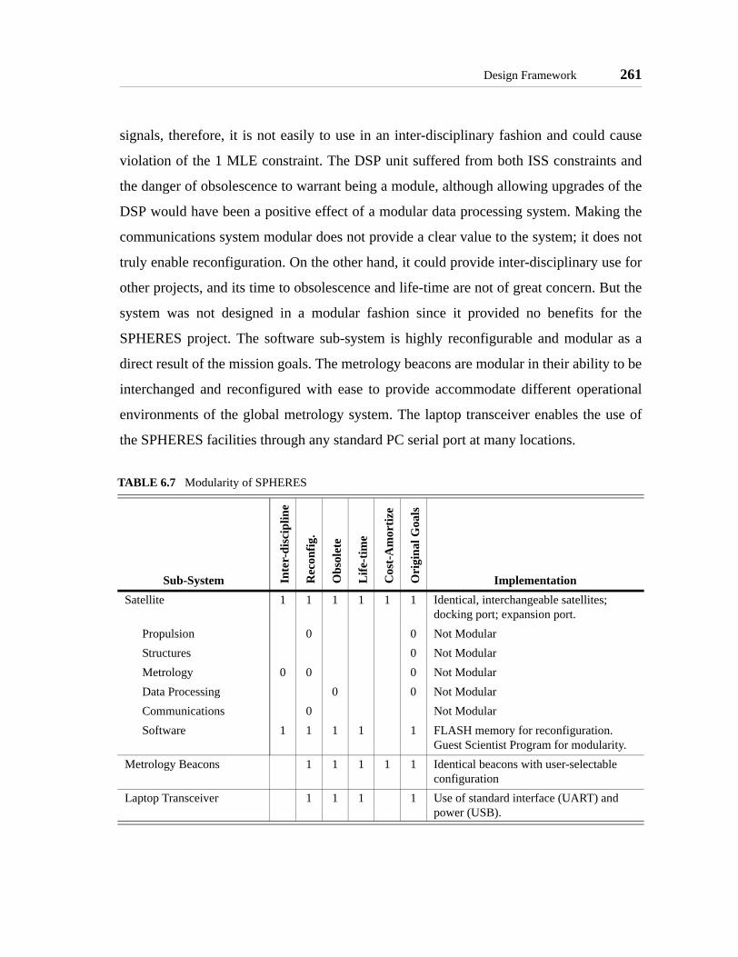
Design Framework 261
signals, therefore, it is not easily to use in an inter-disciplinary fashion and could cause
violation of the 1 MLE constraint. The DSP unit suffered from both ISS constraints and
the danger of obsolescence to warrant being a module, although allowing upgrades of the
DSP would have been a positive effect of a modular data processing system. Making the
communications system modular does not provide a clear value to the system; it does not
truly enable reconfiguration. On the other hand, it could provide inter-disciplinary use for
other projects, and its time to obsolescence and life-time are not of great concern. But the
system was not designed in a modular fashion since it provided no benefits for the
SPHERES project. The software sub-system is highly reconfigurable and modular as a
direct result of the mission goals. The metrology beacons are modular in their ability to be
interchanged and reconfigured with ease to provide accommodate different operational
environments of the global metrology system. The laptop transceiver enables the use of
the SPHERES facilities through any standard PC serial port at many locations.
TABLE 6.7 Modularity of SPHERES
Sub-System Inte
r-di
scip
line
Rec
onfig
.
Obs
olet
e
Life
-tim
e
Cos
t-A
mor
tize
Ori
gina
l Goa
ls
ImplementationSatellite 1 1 1 1 1 1 Identical, interchangeable satellites;
docking port; expansion port.Propulsion 0 0 Not ModularStructures 0 Not ModularMetrology 0 0 0 Not ModularData Processing 0 0 Not ModularCommunications 0 Not ModularSoftware 1 1 1 1 1 FLASH memory for reconfiguration.
Guest Scientist Program for modularity.Metrology Beacons 1 1 1 1 1 Identical beacons with user-selectable
configurationLaptop Transceiver 1 1 1 1 Use of standard interface (UART) and
power (USB).

262 ASSESSMENT OF SPHERES
Principle of Remote Operation and Usability
The SPHERES laboratory was specifically designed for operations aboard the Interna-
tional Space Station, where the operators and researchers are distinct individuals; it was
also designed for operations at the MIT SSL and NASA’s Reduced Gravity Airplane,
where the operators are sometimes the researchers. Therefore, as presented in
Section 4.3.2.8, there are different interfaces of the SPHERES laboratory to satisfy opera-
tions at the different locations.
The Principle of Remote Operations and Usability separates the requirements for opera-
tors and researchers:
• Operator
O1. Provide necessary controls to conduct research efficiently
O2. Ensure safe data transfer regardless of operator actions
O3. Present relevant information for successful run of experiments
O4. Enable operators to provide feedback
O5. Allow real-time communications for selected operations
• Researcher
R1. Minimize efforts to collect data
R2. Allow upload of information
R3. Enable real-time communications for selected operations
R4. Allow scientists to predict results and compare with collected data
The prototype interface concentrated on the development of the facilities and immediate
science feedback, rather than the operation at any specific location. While the interface
had the ability to present custom data in real-time, the data did not aid in operations,
rather, it distracted operators in environment such as the RGA (violating O3). This inter-
face also violated requirement O2, since it saved only recognized data. Because the inter-
face was used only by the SPHERES team, it required no direct feedback mechanism (O4)
or real-time communications (O5, R3). The interface did meet requirement O1, as it
allowed easy operation of the units, informed the operator when tests were running, and

Design Framework 263
when data was received. By collecting processed data the interface attempted to satisfy
requirement R1; data was easy to read from the stored files. The design tools necessary to
load new programs (R2) were available since the prototype design. But the prototype sys-
tems did not include a simulation to allow scientists to predict their results and compare
them, violating requirement R4.
The prototype interface evolved into two separate programs: a ground-based interface and
an ISS interface (Section 4.3.2.8). Further, the SPHERES simulation (Section 4.3.3.1) was
developed to account for the remote location of scientists who are not members of the
SPHERES team. In this manner, the SPHERES laboratory meets all the requirements of
this principle.
The ground-based interface was designed for operations at the MIT SSL, NASA RGA,
MSFC Flat Floor, and other facilities where the operators are either the researchers and/or
members of the SPHERES team. This interface addresses requirement O1 (control of the
facilities) by enabling simple operations for all common tasks and incorporating program
upload (R2) directly into the interface. The availability of optional windows with real-time
state and debug data allows the interface to provide relevant data (O3) when the operators
are the research scientist; otherwise the presented data is only that essential for the opera-
tion of the satellites. This interface saves data in its raw format, so that scientists can do
substantial post-processing and do not loose any information (O2). The interface does
require the operator to initiate data storage, therefore creating the potential situation where
data is not stored due to operator error. To address R1, minimize data collection time, the
SPHERES team developed several Matlab functions to collect the data from the raw data
files created by the interface. The SPHERES simulation and the information provided
with the Guest Scientist Program fulfills requirement R4, allowing the scientist to create
models of their experiments and compare the information. Because this interface was
designed for use in ground-facilities with scientists or SPHERES team members present,
requirements O4, O5, and R3 are not applicable.

264 ASSESSMENT OF SPHERES
While ground operations depend almost entirely on the scientist and the SPHERES Team,
ISS operations depend on more parties: the SPHERES Team, PSI, STP, NASA/ISS Mis-
sion Control, and the astronaut. Therefore, the interfaces for operations aboard the ISS sat-
isfy the requirements in different ways, since they also must meet requirements set forth
by other parties.
The design for control of the satellites (O1) had to meet NASA requirements, apart from
the needs of SPHERES. Therefore, the ISS interface requires the use of several steps to
start a test. These steps take into account the need to ensure the operator select the correct
program and test and is aware of the expected results of each experiment. While the
ground-based interface allows test and maintenance tasks to be performed from the main
window, the ISS interface presents separate windows/processes.
The ISS interface stores data immediately upon starting. Regardless of the operator’s
actions, the program will save all outgoing and incoming raw data, ensuring the data is
safe regardless of the operator’s actions (O2). If a test terminates unexpectedly or is can-
celed by the operator, the file is saved automatically.
The flight GUI presents information to the operator (O3) in several sections. The state
information of the satellites are presented permanently through a status bar. This ensures
the operator is always aware of which units are operating and what program is in use.
Descriptions of the tests allow the operators to know expected results and make decisions
on the test performance. By providing sufficient details on the test, the interface reduces
the dependency of real-time communications with the researcher.
The ISS interface presents a questionnaire to the astronaut at the end of each test, requiring
the astronaut to provide feedback (O4). The questions are written specifically for each test
so that the feedback from the astronaut provides the maximum amount of information to
the scientist. Further, the astronaut is allowed to enter notes freely after the questionnaire,
allowing feedback on topics not originally considered by the scientist. This feature effec-
tively creates an electronic laboratory notebook.

Design Framework 265
Operations of the SPHERES laboratory does not require real-time communications in
general (O5, R3). Through the data download and astronaut feedback mechanisms, the
scientist can determine progress of the research. By interfacing directly with the ISS com-
munications system, the SPHERES facilities can potentially download and upload data
and programs in real-time (if the ISS channel is available at the time), even if telecommu-
nications are not established.
Multiple steps were taken to minimize the data download time (R1). The flight interface
packages all the data from each session. The use of the ISS telemetry system simplifies the
operator’s tasks. At that point the data transfer time is dependent on the NASA command
center availability to distribute the data to PSI/STP and the SPHERES team. Once the data
reaches the SPHERES team, it can be interpreted with the same Matlab tools that were
used for initial testing in the ground facilities, since the flight interface uses the same file
structures as the ground based interface.
The utilities to upload new programs (R2) are fully integrated into the flight interface.
Because a multi-satellite test may require different executable files for each satellite, the
interface maintains the structure of the program, making the existence of separate executa-
bles transparent to the operator. The interface also manages all the preview files and ques-
tionnaires as a single file, so that the astronaut does not have to manage any individual
files.
The use of the simulation and MIT SSL ground-based facilities as an integral part of the
ISS iterative loop (Figure 4.12 on page 97) allows scientists to predict their results prior to
operations aboard the ISS (R4). The facilities are also available after the flight to repro-
duce allow comparison of results. Further, the availability of raw data allows the results of
both ground-based tests and ISS tests to be compared analytically using tools such as Mat-
lab.
6.2.4 Step 4 - Review Requirements and Design• Principle of Requirements Balance

266 ASSESSMENT OF SPHERES
Principle of Requirements Balance
The current design of SPHERES consists of several dozen system-level functional
requirements and over one hundred functional requirements for the sub-systems. This
assessment concentrates on the system-level requirements derived from the mission objec-
tives summarized in Figure 6.10 [SPHERES, 1999].
The system functional requirements consist of 21 hard requirements (those essential for
mission success) and 10 soft requirements (those that would enhance the mission). The
hard requirements stem directly from the need to demonstration formation flight algo-
rithms in 6DOF within the KC-135 and the ISS while facilitating iterative research and
allowing the study of several areas. The soft requirements derive from desire to demon-
strate specific capabilities not fully defined at the time of development (e.g., the mission
objective to demonstrate autonomy tasks) or the need to use ground-based facilities (e.g.
the KC-135) prior to deployment aboard the ISS. Taken numerically, this is an acceptable
division of hard and soft requirements; but one must ensure that the hard requirements
drive the mission, while the soft requirements require only limited resources and effort to
implement.
The following descriptions illustrate how SPHERES achieved requirement balance, even
though it required trade-off’s between the functional requirements, including the desire to
implement several soft requirements.
One-time Use Alkaline Batteries. Not only did the power sub-system teamhave a need for re-chargeable batteries, they had the capability to build aground-based system which has been used continuously since 2001. But theflight hardware utilizes one-time use alkaline batteries. This decision wasnot a trivial one, but one considered necessary due to the high costs associ-ated with certifying a recharging system for flight aboard the ISS. TheSPHERES project team had to balance the need for battery power with theavailable development resources (both time and money were limited at thetime of certification); therefore, while not ideal (especially when the Princi-ple of Optimized Utilization is applied), the use of alkaline batteries balancedthe efforts required to certify the power system for use aboard the ISS withthe resources available.

Design Framework 267
Custom Metrology System. The need for a metrology system that identi-fied the full state of the satellites for formation flight control is a hardrequirement, but one that is not fully quantitative. The requirements for themetrology system were originally specified in "sub-centimeters" (range) and
• Develop a set of spacecraft that interact to maintain position, orientation, and direction.- Satellites require translational, rotational, and attitude control capabilities. (Hard)- Each satellite must contain its own propulsion, avionics, software, power, communica-
tion, and GNC systems within its own structure. (Hard)- Satellites must be able to communicate their relative positions. (Hard)- Satellites should employ handshaking and negotiation for decision-making. (Soft)- Array should consist of at least three distinct satellites. (Soft)
• Allow reconfigurable algorithms, data acquisition and analysis, and provide a truth measure.- Satellite must be able to receive control algorithms. (Hard)- Satellite must be able to acquire, analyze and send data. (Hard)- Allow measurement of relative orientations and positions between satellites. (Hard)- Allow measurement of the satellite states relative to the KC-135 / ISS. (Hard)- Some of the downloaded data must provide health status information. (Hard)
• Enable the testbed to perform array capture, static array maintenance under disturbances(attitude control and station keeping), and retargeting maneuvers.- Should perform self-diagnostic on power up. (Soft)- Must determine relative and absolute position. (Hard)- Must provide sufficient control authority to counteract environmental effects. (Hard)
• Enable testing of autonomy tasks, including fault-detection and recovery, health and statusreporting, and on-board replanning.- Compensate for the failure of any other satellite(s). (Soft)- Detect a total failure of one of the others. (Soft)- Recognize and compensate for minor failures in its subsystems. (Soft)- Able to report any minor failures back to an external monitor. (Soft)- Able to regularly report the status of each of its subsystems. (Soft)- All of the satellites should be physically identical. (Soft)
• Ensure traceability to flight systems via communication, propulsion, structural, avionics,guidance, control, and power capabilities.- Enable traceable control algorithms to future missions. (Hard)- Provide representative dynamics of the propulsion. (Hard)- Provide precision metrology system equivalent to actual applications. (Hard)- Enable data communications equivalent to real missions. (Hard)
• Design for operation in the KC-135, shuttle mid-deck, and ISS.- KC-135- Functionality needs to be demonstrated in <20 sec. (Hard)- Operate within the space confines of the KC-135. (Soft)- Allow for retrieval and restraint during 2g fall section of flight. (Hard)- Meet all applicable KC-135 safety requirements. (Hard)- ISS- Satellites must fit into shuttle mid-deck locker. (Hard)- Enable demonstrations within the confines of the ISS. (Hard)- Must allow protocol test time of two hours. (Hard)- Meet all applicable ISS safety requirements. (Hard)
Figure 6.10 SPHERES Functional Requirements
268 ASSESSMENT OF SPHERES
"degrees" (rotation), but the actual values were determined by the selectedsystem. The final selection of a custom ultrasound and infrared time-of-flight system was mainly a trade-off between acquiring a COTS product andbuilding a custom one. At the time of the development of SPHERES, only ahandful of COTS products existed; the majority of them had a cost beyond15% of the total SPHERES budget, making them unattainable. Further, allthe reviewed systems required modifications from their original configura-tion. Therefore, the SPHERES team decided to develop a custom metrologysystem (Section 4.2.1.1) which would incorporate directly with the othersub-systems. The final design has demonstrated the ability to meet thedesign requirements, with specific quantitative resolutions provided (0.5cm,2.5°) in ground-based 2D operations; 3D operations are yet to be demon-strated aboard the ISS. Ultimately, as the results of tests aboard the KC-135show, the development of a custom metrology system utilized a substantialamount of resources and effort beyond that of any other sub-system. Whilemetrology itself is part of the science being conducted with the SPHERESlaboratory, this requirement did create an unbalance between metrology andall the other sub-systems.
Propellant Selection: CO2. The Selection of carbon dioxide as propellantdoes not appear to be optimal. The use of CO2 means increased safetyrequirements, including the use of a toxic gas and development of a pressur-ized system. Further, it is not possible to replenish CO2 aboard the ISS. Butthis selection was due to the fulfillment of several other requirements:occupy at most one MLE (mass and volume), provide thrust to perform thestrawman maneuvers, allow traceability to spacecraft, and maintain develop-ment costs in control. The selection of CO2 over any other pressurized gasallowed the propulsion system to maintain the amount of resources andeffort invested on it balanced with the other sub-systems, as little customwork was required and the technologies to handle carbon dioxide wereclearly understood. While it required substantial more time investment in thesafety process, it did not require substantial development efforts, which gavebalance to the selection.
Expansion Port. While modularity and reconfiguration was initially builtinto SPHERES, it originally was only conceived as part of the software sys-tem. The development of the expansion port (Section 4.3.3.2), which enableshardware reconfiguration, came late in the process. Therefore, its implemen-tation required that only minor changes be needed from the existing sub-sys-tems. It was essential that the addition of an expansion port did not drive themission beyond its constraints, especially the need to meet launch deadlines(such as CDR, safety reviews, etc.). This required the expansion port to useexistent data channels and to fit within space available in the system. Theresulting expansion port attempts to provide for future projects by using both

Design Framework 269
simple and complex data channels, as well as several power voltages. Theserial and power lines have been utilized in several projects, and their useful-ness demonstrated; no projects have utilized the global memory bus as ofyet. This discrepancy in the use of the expansion port data lines is due to animbalance in the resources and effort put to develop the expansion port. Therequirement for hardware modularity was given low priority and assignedonly limited resources, while the other requirements drove the mission.
Communications Channel Frequency Selection. Enabling iterativeresearch has always been a primary functional requirement for SPHERES.Yet, to meet this requirement two potentially conflicting requirementsexisted: de-couple the software from safety reviews to minimize the over-head time to upload new algorithms and provide the necessary tools to col-lect substantial data. The communications channel has a conflict betweenthese two requirements since the use of an 802.11b wireless LAN interfacecard can provide over 10Mbps of bandwidth utilizing standard COTS equip-ment and publicized protocols; but such a system requires that the softwarebe controlled, since the 802.11b network is part of the ISS controlled envi-ronment. Therefore, the SPHERES team required that the communicationssystem utilize an uncontrolled frequency range. At the time of developmentof the SPHERES testbed, the simplest integration was through the use of916MHz technologies. This required substantial effort in the development ofa custom communications protocol and limited the bandwidth to at best56.6kbps. But, the use of the custom system allowed the software sub-sys-tem to remain decoupled from any safety requirements.
6.2.5 Design Framework Assessment Summary
Having been designed to exhibit the features of the MIT SSL Laboratory Design Philoso-
phy, SPHERES closely follows the principles which derived directly from the philosophy.
The principles of Enabling a Field of Study and Iterative Research have been successfully
implemented in SPHERES. The Guest Scientist Program enables research by multiple sci-
entists by providing the necessary tools for scientists to conduct research in their home
locations (simulation, data analysis) and at remote facilities, with option to be present at
several testing facilities (MIT SSL, NASA RGA, MSFC Flat Floor). The laboratory facil-
itates iterative research by allowing the necessary reconfiguration of algorithms, minimiz-
ing overhead time to repeat experiments and upload new algorithms, and providing
scientists with flexible operations plans. The SPHERES laboratory exhibits the major

270 ASSESSMENT OF SPHERES
traits called for in the principle of Focused Modularity. While modularity did not play a
major role in the design of the individual satellite sub-systems, it did guide the overall
design: the satellites represent a standard satellite bus. Further, the software exhibits mod-
ularity throughout.
The principles of Optimized Utilization and Remote Operations and Usability derive from
the need to operate aboard the ISS, a task inherent in the design of the SPHERES labora-
tory. SPHERES makes an acceptable use of the resources aboard the ISS, although several
resources were not utilized correctly due to the inability to fulfill all existent NASA
requirements with the resources available. SPHERES accounts for all the considerations
raised in the principle of Remote Operations and Usability, providing both the operators
and scientists with the tools to conduct remote research. These include the ability of the
operator to control the experiment, preview expected results, and provide feedback to the
scientist. The scientist has tools to predict results, analyze the data, and compare results.
The correct use of ISS resources enable real-time communications between the operator
and the scientist if necessary.
SPHERES provides the ability for scientists to test metrology, control, and autonomy
algorithms in a representative environment, achieving TRL 5 or TRL 6 in most cases, and
TRL 7 in a selected few. This ability allows SPHERES to meet the principle of Incremen-
tal Technology Maturation because the cost of SPHERES is minimal compared to the full
cost of an operational mission. By providing a representative environment at low costs,
where the technologies can be demonstrated and the risks reduced, SPHERES can allow
the total cost and risk of an operational mission to be reduced.
The principle of Requirements Balance originated from the observation that the two
guidelines behind the development of SPHERES did not specifically account for the lim-
ited resources available for a mission. The successful development of the SPHERES labo-
ratory indicates that enough requirements balance took place to create the design. But
review of the implementation demonstrates that further requirements balance could have

Evaluation Framework 271
occurred to prevent incosistencies in the effort and resources put into the development of a
few sub-systems (e.g., metrology), while others (e.g., power, expansion port) could have
used further resources to provide important benefits.
6.3 Evaluation Framework
An ISS NGO evaluator would be provided with a proposal that describes the design of a
mission with enough details to address all of the microgravity laboratory design princi-
ples. The review by the NGO addresses the following points:
• Correct utilization of ISS resources
• Technology advancement
• Mission scope
In the case of SPHERES an ISS NGO would receive information similar to that presented
in the SPHERES Critical Design Reviews (Technical: [SSL, 2002] and Science: [SSL,
2002a]) and the Safety Data Packages [SPHERES, 2001]. This information is now used to
asses SPHERES using the evaluation framework presented in Section 5.11.
Principle of Iterative Research
The stated science objectives of SPHERES (develop metrology, control, and autonomy
algorithms for distributed satellite systems) clearly indicate the need for iterations. To
demonstrate the maturation of algorithms requires running multiple tests and evaluating
the results until the desired performance is met. The ISS evaluator must asses the ability of
SPHERES to support iterative research based on the evaluation framework:
1. Does the experiment collect the data necessary to support or refute thehypothesis?
It is not the job of the ISS NGO evaluator to guarantee that the proposedfacilities collect all the data necessary for mission success, but it is in thebest interest of the ISS program to determine if a project has the ability tocollect relevant data through either custom hardware or systems availableaboard the ISS. In reviewing SPHERES, the evaluator can see the existenceof two measurement systems (inertial and global metrology systems), the useof the communications system to download data to an ISS SSC, and the use

272 ASSESSMENT OF SPHERES
of the ISS telemetry system to download the data to ground.
The SPHERES CDR clearly indicates that the sensors of the satellites pro-vide the necessary measurements to perform tests of the different algo-rithms; the evaluator need not question the proposal unless there is anobvious question on the ability to collect the data. In the case of SPHERESthere is no obvious failure to collect the data, and the resources aboard theISS have been used correctly to this purpose.
2. Do the operational plans of the facility provide sufficient flexibility for effi-cient iterations?
The SPHERES operational plans clearly include wide flexibility, but the ISSNGO should notice that a lot of this flexibility depends on periodic opera-tions aboard the ISS. The ground-based tests prior to ISS deployment areoutside of the control of the ISS program, and allow scientists substantialresearch time to analyze data and come up with new algorithms. But the planfor operations aboard the ISS depends on having test sessions every twoweeks, at which point the ISS staff will play a critical role in the effective-ness of iterations. Therefore, the ISS NGO staff must, at least, make notethat the ability of this facility to perform iterations requires allocation ofresources by the ISS program. In the case of SPHERES the resources are notmission critical; that is, if one or two sessions are missed, the program willnot fail. Therefore, it is possible to allocate the resources without unduestress on the ISS program.
3a. Can the facility perform multiple experiment runs with repeatability andreliability?
The facilities of SPHERES have been designed specifically to allow for rep-etitions of tests aboard the ISS, as well as multiple other locations. The oper-ator can start tests with minimal setup time; the interface provides simplecontrols to start and stop tests. Further, the reliability of SPHERES has beendemonstrated in ground-based facilities. But the project does have a majorlimitation in its ability to support repetition: depletable propellant and batter-ies. The ISS NGO needs to evaluate the ability of SPHERES to perform rep-etitions over an extended period of time, and get assurances that theconsumables can be resupplied to the ISS for continued operation.SPHERES has limited launch capabilities for consumables; currently theyaccount for up to six months of operation. This is a reasonable time frame,although the ISS NGO should make note of this limitation in the review ofSPHERES.
3b. Can the facility be reconfigured while in the ISS in such a way to providenew meaningful results and/or reflect changes in the hypothesis?
The primary scientific objective of SPHERES is to develop algorithms for

Evaluation Framework 273
distributed satellite systems. The SPHERES facilities aboard the ISS allowreconfiguration of the algorithms being tested via wireless links between thesatellites and the ISS SSC. Therefore, SPHERES allows reconfiguration ofboth individual algorithms and of high-level hypothesis.
The proposed expansion port of SPHERES allows further reconfiguration,including the change of hardware. But because these changes require launchof further hardware to the ISS, an ISS NGO evaluator must first see that theprogram has the resources available to deliver these items to the ISS.Because SPHERES has not yet demonstrated this capability, the evaluatorshould only consider software reconfiguration under this question.
Based on these reviews, an ISS NGO evaluator can see that the SPHERES laboratory
enables iterative research at all the levels presented in Figure 5.1 for software-based
research. While several reservations exist on the ability of the laboratory to support itera-
tive research in the long-term, the proposed initial mission should be successful.
Principle of Enabling a Field of Study
Review of the Science CDR [SSL, 2002a] immediately identifies the field of study cov-
ered by the SPHERES laboratory: metrology, control, and autonomy algorithms for dis-
tributed satellite systems. The development of these algorithms is essential for several
upcoming missions; their maturity through demonstration in a space environment can
greatly reduce the risk of the operational missions. The same presentation contains an
overview of the Guest Scientist Program, which provides the capabilities to support multi-
ple scientists:
• Efficient data paths - Data transfer to and from the ISS includes the use ofthe ISS data system to minimize the delay in delivery to the SPHERES pro-gram. The ISS NGO evaluator wants to ensure that if the ISS systems areused, the program does not create undue delays for the data to reach the sci-entists, countering efficient use of ISS resources. The SPHERES team doesnot create any further delays in the delivery of data, which is immediatelyforwarded to the scientists.
• Data analysis tools - The evaluator can determine from the Science CDRthat guest investigators have a simulation to predict results at their homefacilities. Further, the GSP clearly defines all standard SPHERES data pack-ets and allows scientists to define their own structures.

274 ASSESSMENT OF SPHERES
• Flexible operations - As with iterative research, the SPHERES plans do pro-vide substantial flexibility, but require the allocation of resources by the ISSprogram. This allocation of resources is within the capabilities of the ISS,although it may have to be reviewed in the long term.
• Reconfiguration - As before, demonstrated reconfiguration of the SPHERESfacilities aboard the ISS is limited to software changes. SPHERES doesallow multiple scientists to utilize the ISS facilities as long as their testsrequire only software. To allow hardware reconfiguration, the SPHERESprogram will need to demonstrate the capability to deliver new hardware tothe ISS.
From the ISS program point of view, the SPHERES laboratory has been correctly
designed to allow research on a substantial field of study (algorithms for distributed satel-
lite systems) and has created the necessary programs and facilities to support multiple sci-
entists. These programs do utilize ISS resources, but not beyond the capabilities of the ISS
program. Therefore, the ISS NGO would have no recommendations to change any aspect
of SPHERES with respect to the principle of Enabling a Field of Study.
Principle of Optimized Utilization
An ISS NGO evaluator must determine if a project makes proper use of the special
resources available at the ISS. The design of SPHERES demonstrates utilization of many
resources available at the space station. Further, the presented trades between operational
environments indicate that the program would not have the resources to operate as a stan-
dalone space mission; that it does not have the need for such operations; and most impor-
tantly, that it would loose many of the benefits obtained by operating in the controlled
environment of the station with human interaction (i.e., would no longer create a risk-tol-
erant environment for algorithm research) if it were a free flyer program. Next, the evalu-
ator should asses whether the utilized resources of the ISS are used correctly and if other
resources exist to benefit the program and at the same time make better use of the station:
• Crew - SPHERES is programmed to utilize approximately six hours of crewtime each month, accounting for half an hour of setup, two hours of tests,and half an hour of breakdown. In terms of the absolute amount of time, thisis an acceptable amount, towards the lower side of expected crew use.

Evaluation Framework 275
The importance of the crew involvement as an integral part of the scienceconducted with SPHERES stands out. SPHERES requires the astronaut totruly become an extension of the researcher, requiring the astronaut to under-stand some of the science aspects and make decisions based on their ownobservations. From the ISS NGO perspective, this is both an asset and a con-cern. It is an asset because astronauts will be researchers in space, directly inline with the main objective of the station. It is a concern because the astro-naut may be responsible for the scientific success of the mission. Therefore,the ISS NGO evaluator will need to put extra emphasis on the need to satisfythe principle of Remote Operation and Usability.
• Power - The SPHERES facilities aboard the ISS utilize minimal amount(50W) of power compared to that available for experiments. But SPHERESrequires the delivery of custom batteries to the station, rather than usingexisting power resources. For the ISS program this means the use of bothlaunch, storage, and disposal resources for a resource widely available at thestation. Upon review with the SPHERES team, the evaluator would learnabout the lack of resources to develop a recharging station and put it throughthe necessary safety review processes. The evaluator should then present theproblem to the ISS NGO leaders, who have the responsibility to review theprocesses required to allow better utilization in the future. Upon review ofthe procedures, the ISS NGO staff should continue in contact with theSPHERES team to encourage them to better utilize the power resources.
• Telemetry / communications - SPHERES utilizes a small amount of teleme-try during normal operations; its real-time communications are limited topre-specified operating sessions. The use of the existing SSC, which com-municates directly with the ISS network, simplifies integration of the projectwith existing resources. Therefore, SPHERES successfully utilizes thetelemetry and communications resources of the ISS.
• Long term experimentation - The expected mission life of six months to oneyear presented in the critical design review is a valid utilization of the ISS.But this longevity depends strongly on the availability of the two consum-ables used in SPHERES: batteries and propellant. The ISS NGO evaluatorshould be interested in knowing the capabilities of the facilities in case eachof the resources run out, therefore should ask the SPHERES team to presentcontingency plans in case consumables run out.Note that utilizing rechargeable batteries would better ensure long-termexperimentation, reinforcing the need for the SPHERES team to reconsiderthe use of disposable batteries.
• Benign environment / atmosphere - The presented design for the SPHERESfacilities aboard the ISS require a pressurized atmosphere; the project takesadvantage of this resource to greatly reduce its costs and development time.

276 ASSESSMENT OF SPHERES
Further, SPHERES makes use of the controlled environment of the station toreduce the risk involved in developing new algorithms.
SPHERES successfully utilizes four of the five ISS resources identified for special consid-
eration. The crew is involved directly with the science, beyond mechanical or repetitive
activity. The ISS telemetry data system is well integrated to the facilities. Assuming no
unexpected problems with delivery of consumables, the longevity of the project is appro-
priate. The project utilizes the benign environment to reduce both its costs and risks.
While the power consumption is minimal in terms of available ISS power, SPHERES
requires its own power source (disposable batteries). The project must be reviewed to cor-
rect this problem, which would not only reduce delivery costs to the station, but also help
ensure the longevity of the mission.
Principle of Focused Modularity
To review the modularity of SPHERES, the ISS NGO considers the three main elements
of the facilities delivered to the ISS:
• Satellites - The satellites do not exhibit any modularity of their sub-systems.The structure does not allow separation of the sub-systems, therefore it is notpossible to utilize any specific part of the satellites in other projects. Areview of the sub-systems would identify the usefulness of some modularityin the satellites. The communications system could be modular, providing asimple wireless communications interface to other projects. If the batterieswere rechargeable, they could provide power to new facilities. While insome cases the microprocessor could be made modular, the selectedSPHERES processor is too specific to the application, therefore there is noneed to make it modular from the ISS perspective.The satellites do provide the ability for reconfiguration via their expansionport (requires hardware delivery) and the update of the software and userinterfaces (via the ISS communications channels). Therefore, the satellitescan be used for as yet unforeseen projects.
• Metrology beacons - The metrology beacons are identical and can be recon-figured easily. While they require specific signals to operate, there are nolimitations which restrict their use with other projects beyond the SPHERESfacilities. Therefore, these beacons could become a tool available for otherproject which needs a ranging system and can accommodate the signal tim-ing requirements.

Evaluation Framework 277
• Communications - The transceiver provided by SPHERES operates with anymodule that has an RS232 serial interface (UART). This allows the moduleto be used with a wide range of projects beyond SPHERES. But it requiresthat each new project utilize exactly the same communications hardware,with its custom firmware, greatly reducing the ability to consider the com-munications transceiver a modular entity. Like with the satellites, theSPHERES communications transceiver could be reviewed to allow for bettermodularity.
From the ISS perspective, SPHERES offers little modularity. The satellites provide sub-
stantial reconfiguration capabilities, allowing their use in future projects. But this depends
on the ability to launch hardware and develop new software. Further, these new uses
depend on the SPHERES team cooperating with new scientists, and does not directly pro-
vide new capabilities for the station. Therefore, the satellites do not provide any substan-
tial modularity to the station. The communications system, while modular on the ability to
operate with any RS232 serial line, requires the use of special hardware and firmware,
limiting its usefulness. The metrology beacons do provide a new system which could be
made available to new users. A clear interface exists and there are no physical limitations
to their use by other projects.
Principle of Remote Operations and Usability
This principle calls for the reviewer to determine if the proposed program has clearly iden-
tified the data and information requirements to provide scientists with sufficient data and
operators with the necessary information to conduct science. The SPHERES program
clearly identify the data paths, allows scientists to create custom data, and provides meth-
ods to test the selected data through actual experiment runs prior to deployment to the ISS.
Therefore, the ISS program has reasonable assurances that the data collected aboard the
station will be sufficient for the scientist. The requested real-time communications are not
intended for the scientists directly, but rather for the SPHERES team to support the opera-
tor during the first two operating sessions. Thereafter, the operator is expected to use the
facility independently, so the ISS NGO must ensure that the operator has enough informa-
tion to perform the required tests in the future.

278 ASSESSMENT OF SPHERES
The principle provides the following guidelines to evaluate the capability of an operator to
successfully run tests:
• The operator has the necessary interfaces to control the facilities aboard theISS in an efficient and safe manner.The SPHERES interface provides the operator with a clear procedure to loadprograms, select tests, and start experiments. Starting an experiment is con-tingent on the astronaut enabling the necessary satellites, which implies theastronaut has control of them. The interface ensures that whenever a test is inprogress, the stop command is always available to the astronaut. Therefore,the operator does have the necessary controls to conduct tests in an efficientand safe manner.
• The operator is presented the information necessary to successfully evaluateexperiments.The SPHERES documentation indicates that the operator is to be presentedwith a preview (written explanation with optional images and/or animations)of the experiment before a test is started. The description of each test willprovide the astronaut with a clear idea of the expected results. A result codewill allow the astronaut to compare their observations with the determinationof the algorithm, providing further information to determine if the test wassuccessful. Using this information, the operator can make the decision torepeat a test or move on with the program.Therefore, upon review of the existing documentation, the SPHERES pro-gram appears to provide the necessary information for astronauts to evaluateexperiments. Still, the ISS NGO must clearly establish that this depends onthe SPHERES team providing the information continuously. Further,because astronauts conduct a wide range of experiments on many areas, theyshould not be held responsible for any misinterpretations of the presentedpreviews.
• The operator can provide feedback to the research scientists from theirobservations in the operational environment.The SPHERES project accounts for the ability of the operator to providefeedback in two manners: the use of a survey at the end of each experiment,with questions directly related to the science; and the ability of the operatorto provide open feedback after the survey. This information is storedtogether with the data collected during the experiment, and transferred at thesame time. Therefore, the scientist can always correlate the collected datawith astronaut feedback to better evaluate the success of an experiment.
From the ISS NGO perspective, it appears that the SPHERES team has accounted for all
the necessary tools to allow successful remote operations of the SPHERES facilities, even

Evaluation Framework 279
without real-time communications between the scientists and the operator. The design
does depend on the correct interpretation of the descriptions, images, and movies provided
in the previews and result codes presented after each test. Therefore, the possibility for
operator error exists, but it has been reduced by the providing the astronaut information
both before and after each test.
Principle of Incremental Technology Maturation
By correctly utilizing the environment of the ISS, SPHERES provides scientists with a rel-
evant environment to test new metrology, control, and autonomy algorithms aboard the
space station. The ability to run multiple tests, change operating conditions, and reconfig-
ure the software covers the necessary operating points to demonstrate the technology. The
fact that scientists can present previews demonstrates the ability of SPHERE to enable
predictions of performance; the data collection allows comparison of these predictions
with actual results. Therefore, SPHERES satisfies the requirements to advance technolo-
gies to TRL 5.
SPHERES can achieve TRL 6 and TRL 7 only for those programs where the hardware
represents either operational models of the sub-systems (TRL 6), or full scale prototypes
of the operational system (TRL 7). Therefore, the ability of SPHERES to advance technol-
ogies beyond TRL 5 depends on the specific mission being considered. The ISS NGO
evaluator can consider that TRL 6 may be achieved for a limited set of missions; the eval-
uation should not consider the capability of SPHERES to mature technologies to TRL 7
unless specifically addressed by the SPHERES documentation. Therefore, SPHERES is
considered a laboratory which allows technology maturation to TRL 5 and TRL 6.
6.3.1 ISS NGO Evaluation Summary
Overall the SPHERES laboratory successfully implements the features called for in the
design principles. The deployment of the SPHERES facilities to the ISS present a unique
opportunity to expand the science conducted aboard the ISS for more than a single
research program. A clearly established Guest Scientist Program opens up research aboard

280 ASSESSMENT OF SPHERES
the ISS to multiple scientists conducing research on distributed satellite systems metrol-
ogy, control, and autonomy algorithms. The laboratory clearly accounts for the need to
facilitate iterative research through its capabilities to repeat tests with minor overhead and
the ability to reconfigure the software to enable modifications of algorithms and hypothe-
sis. Utilizing SPHERES, these algorithm technologies can be matured to TRL 5 or TRL 6
in most cases.
SPHERES makes correct utilization of the facilities aboard the ISS. The crew, telemetry,
long-term experimentation, and benign environment resources are used appropriately.
While SPHERES minimizes its power consumption, to levels almost negligible to the
availability of power aboard the ISS, it requires the launch of power sources (batteries)
which have mass and volume not negligible to the ISS. Therefore, an ISS NGO would
strongly urge the SPHERES project to upgrade their facilities to make use of the power
sources available in the ISS. Further, the use of consumable CO2 as propellant creates
important concerns about the ability of the facilities to operate over the long-term; while
the ISS NGO cannot provide a reasonable substitute, the SPHERES team should provide
the evaluator with contingency plans on how to obtain partial use of the SPHERES facili-
ties aboard the ISS in the case where the propellant is not available.
The facilities provided to the astronauts aboard the ISS provide substantial tools to make
the operator an extension of the scientist. Not only does the operator start and stop tests,
they also evaluate the experiments to determine, without real-time scientist interaction,
whether a test was successful or not and when to repeat tests or move on with a program.
The interface provides operators with substantial information to make these decisions.
Further, they allow the astronaut to provide feedback to the scientist, effectively creating
an electronic laboratory notebook where the astronaut can make annotations about each
test.
Chapter 7
CONCLUSIONS
7.1 Thesis Summary
The objective of this thesis is to create a design methodology for the development of
microgravity laboratories for the research and maturation of space technologies. This
goal is motivated by the desire to combine the experiences learned by staff of the MIT
Space Systems Laboratory through more than two decades of microgravity research
aboard the Space Shuttle, MIR, and the International Space Station. This research includes
experiments with the Middeck 0-g Dynamics Experiment (MODE), the Dynamic Load
Sensors (DLS), and the Middeck Active Control Experiment (MACE). Further motivation
arises from the call by the National Research Council to create a non-governmental orga-
nization to manage all aspects of research on the ISS in such a way that the research com-
munity [has] early, substantive, and continuing involvement in all phases of planning,
designing, implementing, and evaluating the research use of the ISS such that basic and
applied scientific and engineering uses [of the ISS are] selected on the basis of their scien-
tific and technical merit, as determined by peer review. Further, the NRC report states that
the organization must be flexible and capable of adapting over time in response to chang-
ing needs and lessons learned [NRC, 1999].
The development of the design methodology follows the steps of the scientific method:
objective definition, hypothesis formulation, experimentation, results analysis, and con-
clusions determination. Based on the objective defined above, the hypothesis states that
281

282 CONCLUSIONS
the use of the International Space Station as a host and following the MIT SSL Laboratory
Design Philosophy as design guidelines enable the development of a low-cost environ-
ment for the development and operation of facilities to conduct space technology
research. The experimentation consists in the design, implementation, and operation of
the SPHERES Laboratory for Distributed Satellite Systems. The laboratory consists of
several facilities, including a simulation, ground-based operations for 2D tests, and opera-
tions aboard the ISS for 3D tests. Analysis of the design of SPHERES, the MIT SSL Lab-
oratory Design Philosophy, and the resources and operations of the ISS results in the
creation of the Microgravity Laboratory Design Principles, a design framework for scien-
tists to develop new laboratories, and an evaluation framework for ISS staff to determine
if a project utilizes the station correctly. The thesis concludes with the application of both
frameworks to the SPHERES laboratory.
In order to better understand the existing resources available to mature space technologies
and how research is performed at remote locations, Chapter 1 presents an overview of the
NASA Technology Readiness Levels used to determine technology maturation; it reviews
existing facilities that allow research in actual or simulated microgravity conditions; and
reviews existing remote laboratories. The NASA TRLs provide an example of an existing
methodology to evaluate a technology after its testing environment has been designed and
the tests conducted. They also provide specific information on the requirements of a labo-
ratory designed to demonstrate space technology maturation.
Chapter 1 reviews the microgravity facilities and remote research facilities summarized in
Table 7.1. The review of existing facilities includes facilities located at the home location
of researchers, such as simulations, robots, and air tables. Remote ground-based facilities,
including flat floors, drop towers, neutral buoyancy tanks, and reduced gravity airplanes,
are researched to determine their capabilities and operations. The Space Shuttle and Inter-
national Space Station are the only space-based environments currently available for
research in a microgravity environment. Their capabilities and operations are reviewed.
The operations, capabilities, and research conducted aboard previous space based research
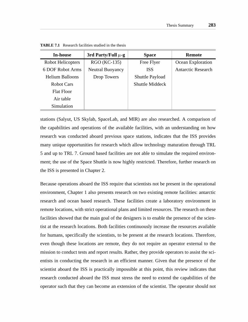
Thesis Summary 283
stations (Salyut, US Skylab, SpaceLab, and MIR) are also researched. A comparison of
the capabilities and operations of the available facilities, with an understanding on how
research was conducted aboard previous space stations, indicates that the ISS provides
many unique opportunities for research which allow technology maturation through TRL
5 and up to TRL 7. Ground based facilities are not able to simulate the required environ-
ment; the use of the Space Shuttle is now highly restricted. Therefore, further research on
the ISS is presented in Chapter 2.
Because operations aboard the ISS require that scientists not be present in the operational
environment, Chapter 1 also presents research on two existing remote facilities: antarctic
research and ocean based research. These facilities create a laboratory environment in
remote locations, with strict operational plans and limited resources. The research on these
facilities showed that the main goal of the designers is to enable the presence of the scien-
tist at the research locations. Both facilities continuously increase the resources available
for humans, specifically the scientists, to be present at the research locations. Therefore,
even though these locations are remote, they do not require an operator external to the
mission to conduct tests and report results. Rather, they provide operators to assist the sci-
entists in conducting the research in an efficient manner. Given that the presence of the
scientist aboard the ISS is practically impossible at this point, this review indicates that
research conducted aboard the ISS must stress the need to extend the capabilities of the
operator such that they can become an extension of the scientist. The operator should not
TABLE 7.1 Research facilities studied in the thesis
In-house 3rd Party/Full µ-g Space RemoteRobot Helicopters RGO (KC-135) Free Flyer Ocean Exploration
6 DOF Robot Arms Neutral Buoyancy ISS Antarctic ResearchHelium Balloons Drop Towers Shuttle Payload
Robot Cars Shuttle MiddeckFlat FloorAir table
Simulation

284 CONCLUSIONS
only conduct repetitive tasks which could be automated; the ability of the human operator
to process information and make educated decisions must be used as an extension of the
scientist.
Chapter 2 identifies the challenges of microgravity research observed in the review of
present and past research facilities in Chapter 1. These challenges are:
• Risk - Every space mission has inherent risks, the possibility of failure atsome step of the mission. The risk considered in this thesis involves the pos-sibility of a facility failing in such a way that research can no longer be con-ducted and technology maturation is not achieved. The goal in thedevelopment of the design methodology for microgravity research is toallow a laboratory to reduce the risk of research for technology maturationand of the operational mission.
• Complexity - The complexity of space missions grows increasingly as a mis-sion approaches operations. The need to account for system integration with-out the ability to test all the components usually leads to increasedcomplexity to reduce the possibility of failure; but the increased complexityadds cost to the mission, as well as more failure modes. Therefore, it is desir-able to reduce the complexity by allowing tests of integrated systems atevery step.
• Cost - As a mission approached operational state, its costs increase substan-tially due to the increase of risk and cost involved, as well as the need toaccount for the space environment. The use of a microgravity laboratoryshould allow the cost to be controlled by providing model environments thatbetter represent the operational environment.
• Remote Operations - Operations aboard the ISS are necessarily remote; thescientist remain in the Earth, while the operator conducts tests aboard theISS. To efficiently conduct research, the operator must be provided with thenecessary tools to assess experiments and make decisions that help toadvance the science, even if it is not possible for the scientist to be in real-time communications with the operator.
• Visibility - Space missions usually stand at the extremes of visibility by thepublic (and funding sources). A mission that is very visible cannot take anyrisks that could result in failure, many times leading to conservative sciencegoals and/or an increase in the cost of development to minimize the risk inthe use of new technologies. On the other hand, missions with low visibilityusually don’t receive the necessary resources. Therefore, it is desirable thatmissions receive resources due to their scientific merits, rather than their vis-ibility.

Thesis Summary 285
Next, the chapter presents an in-depth review of the environment and resources of the
International Space Station that can help in overcoming these challenges. The chapter
introduces the modules that form the ISS, concentrating on those that have been specifi-
cally designed to support research: US Destiny Laboratory, US Centrifuge Accommoda-
tions Module, US Integrated Truss Attachments, Japanese Experiment Module, ESA
Columbus Module, and two Russian Research Modules. Further, the ISS provides scien-
tists with several shared resources: controlled environment, power, communications, ther-
mal management, cryofreeze systems, and payload stowage. The station will also provide
up to 22 (most under development) shared research facilities for specific areas such as bio-
technology, materials processing, human physiology, and more. But no space technology
facilities are planed. The research identifies five special resources of the International
Space Station which directly help to overcome the challenges of microgravity research:
• Crew - The presence of humans aboard the ISS helps reduce the risk, com-plexity, and cost of missions to research space technology maturation.Humans can determine incorrect operation of an experiment, preventing crit-ical failures in facilities aboard the ISS, therefore reducing the risk. The useof the crew allows scientists to reduce the complexity and cost of facilities,since they do not require expensive automation tools to operate and collectdata. Further, humans can perform direct observations and provide feedbackto the scientists.
• Communications - Existing communications equipment at the ISS reducesthe cost of missions. More importantly, the availability of real-time commu-nications and a substantial bandwidth for data transfer allows scientists tocommunicate with the operator as needed. The scientist can upload data forthe operator to review, and download their data in an efficient manner. Theoperator can ask questions to the scientist with little delay.
• Long-term experimentation - The ability to conduct research over extendedperiods of time lowers the effects of visibility on a mission. A project whichis researched aboard the space station for a long time will not have the publicvisibility and impact of other missions, but the presence of the project aboardthe ISS adds visibility among the scientific community.
• Power - The ISS provides substantial amounts of electrical power, as well asseveral gases. This helps missions reduce their cost, since power sources andstorage are no longer required of each project. Further, this reduces the com-plexity and risk of a mission, due to the simplified power sub-system andguaranteed availability of power over extended periods of time.

286 CONCLUSIONS
• Benign Environment / Atmosphere - The benign environment of the ISS cre-ates a risk-tolerant environment for research projects. The availability ofhumans to oversee operations, combined with the ability to repair faults,reduces the risk of a mission. The availability of an atmosphere allowsprojects which operate in the pressurized modules to develop their hardwarein standard ground-based facilities, without the need to account for theeffects of an actual space environment. This results in reduced cost and com-plexity of the mission.
The benefits of utilizing the ISS are summarized in Table 7.2.
Research aboard the ISS covers multiple fields through several operational modes. Three
types of operations were identified: observation, exposure, and iterative experiments.
Observation experiments involve equipment and/or astronauts making observations of the
Earth or space and providing that information to scientists on Earth. Exposure experiments
require the presence of the test artifact in the microgravity environment of the ISS, either
in the pressurized areas (e.g., effects of microgravity on humans) or exposed areas (e.g.,
materials exposure to space radiation). These experiments do not process any data while
the artifacts are aboard the ISS; all data is analyzed in ground-based facilities after the
exposed artifacts return to Earth. Iterative experiments collect data while aboard the ISS;
TABLE 7.2 Benefits of the ISS for microgravity research
Resource Ris
k
Com
plex
ity
Cos
t
Rem
ote
Ope
ratio
ns
Vis
ibili
ty
Crew ↓ ↓ ↓Communications ↓ ↓Long-term experimentation ↓Power Sources ↓ ↓ ↓Atmosphere ↓ ↓ ↓
↓ = reduces challenge

Thesis Summary 287
this data is used by either the astronauts or the scientists to review the experiment and con-
duct new tests until the desired results are obtained.
Three main ares of research have been identified: educational, pure science, and space
technology. Educational experiments provide methods for students at all levels to become
involved with space experiments. Pure science missions provide insight into how systems
behave differently in microgravity and full gravity conditions; they address the better
understanding of physical laws and biology. Space technology experiments allow research
to develop products for use in space missions and facilitate access to space. The thesis spe-
cifically addresses the design of iterative space technology missions aboard the ISS.
Chapter 3 introduces three past MIT SSL microgravity programs. The Middeck 0-gravity
Dynamics Experiment flew on STS-48 and STS-62 to measure the non-linear dynamics of
fluid slush and jointed structures. The Dynamics Load Sensor experiment operated aboard
the MIR space station for approximately three years to measure loads of humans as part of
the ISS risk mitigation program. The Middeck Active Control Experiment flew on STS-67
and was operated by Expedition One aboard the ISS. The first mission developed dynam-
ics and controls tools for predicting and refining robust, multi-variable control algorithms.
The ISS mission of MACE studied dynamics and controls technologies ranging from neu-
ral networks to nonlinear dynamic characterization to adaptive reaction wheel isolation.
The MIT SSL Laboratory Design Philosophy was developed from the lessons learned in
the development and operation of these experiments. The philosophy calls for new labora-
tories to exhibit a specific set of features that facilitates research of dynamics and controls
experiments. The philosophy is based on the need of a mature control algorithm to be
demonstrated in a valid environment; produce repeatable and reliable results; allow the
determination of simulation accuracy; and identify performance limitations, operational
drivers, and new physical phenomena. For a laboratory to enables demonstration that
show characteristics are met, the MIT SSL Laboratory Design Philosophy calls for a labo-
ratory to exhibit the following features:
288 CONCLUSIONS
• Facilitating Iterative Research - A laboratory must allow scientists to con-duct research following the scientific method: formulate a hypothesis, designan experiment, run tests, collect and analyze data, and compare the resultswith the hypothesis to demonstrate the problem has been solved or modifythe hypothesis to run new tests. This is an iterative process; the research iter-ates on multiple hypothesis until the desired performance is achieved. Spe-cifically for the dynamics and control experiments conducted at the MITSSL, a laboratory must allow formulation of new models (dynamics) andalgorithms (control) based on the analysis of collected data and is compari-son with predicted results.
• Support of Experiments - The features that support experiments ultimatelyfacilitate the iterative research process by reducing the time to conductexperiments and providing relevant data. Several features encompass thesupport of experiments:
- Data Collection and Validation - A laboratory must provide the facilitiesnecessary to collect substantial data which can support or refute thehypothesis. The facility must provide methods to validate the accuracyand precision of the data independently of the original sensors used tocollect the data.
- Repeatability and Reliability - The facilities must allow easy repetition ofexperiments with minimal time invested in setting up and starting newtests. Further, the facility must be reliable such that each test is conductedwith reasonable expectations that the environment is controlled and anychanges external to the experiment are observed.
- Human Observability and Manipulation - A dynamics and controls labo-ratory allows humans to directly or indirectly observe every step of theexperiment without the need for expensive data analysis when an obser-vation can be used to determine results. Further, the ability of humans tomanipulate the facilities allows humans to modify the experiment condi-tions.
- Supporting Extended Investigations - To allow iterative research, a labo-ratory must provide scientists with substantial time to analyze data anddetermine the need of new hypothesis and/or design of new experiments.
- Risk Tolerant Environment - A laboratory for research must provide anenvironment where a scientist can take risks in the design of their experi-ments. Specifically in the case of dynamics and control algorithms, thescientists should be able to push the limits of their algorithms to deter-mine the performance limitations without the possibility of a critical fail-ure to the facilities.

Thesis Summary 289
• Support Multiple Investigators - Aerospace research involves the study ofa wide range of areas. Even within the dynamics and control fields, manyscientists come up with different hypothesis, all of which could achieve thedesired performance. Therefore, a laboratory must support multiple scien-tists to test their different hypothesis. This enables the use of a laboratory todetermine the best solution among the field, rather than provide a single datapoint within the field.For collaborative science to be effective it must allow each scientist toachieve goals they would otherwise not be able to do on their own. Theexperiments developed for collaborative research must support multipleinvestigators by design. These experiments must identify the common ele-ments shared between scientists, and allow individuals to add their owncomponents for their specific research. This requires a systematic approachwhich must clearly define the goals and structures of the collaboration whilecreating trust between the parties. Effective inter-personal and data commu-nications channels must be established
• Reconfiguration and Modularity - The ability to reconfigure an experi-ment provides benefits to facilitate the iterative research process (redefinethe experiments and/or hypothesis) and to support multiple investigators(allow individuals to utilize science-specific components). The use of modu-lar systems allows for simpler methods to allow reconfiguration. Several fea-tures are considered for reconfiguration and modularity:
- Generic versus Specific Equipment - The facilities that support collabora-tive research must identify the generic equipment which supports all sci-entists involved in the research. Provisions must be made for scientists toprovide science-specific equipment. This can be in the form of eitherhardware or software.
- Hardware Reconfiguration - Hardware reconfiguration refers to the abil-ity to change the hardware not only to support multiple scientists, but alsoto change the configuration of the facility for individual tests. In the areaof dynamics and control the hardware configuration of a test apparatusdirectly affects the results by changing the dynamics of the system. Hard-ware reconfiguration also allows the addition of new sensors and actua-tors to better represent the intended system.
- Software Reconfiguration - The need to support iterations and multiplescientists requires that facilities provide software reconfiguration. Thecorrect use of software reconfiguration can lead to the development of agood platform where multiple scientists can implement their own mod-ules for their specific research area. This development must utilize simpleAPIs that enhance the collaborative efforts.
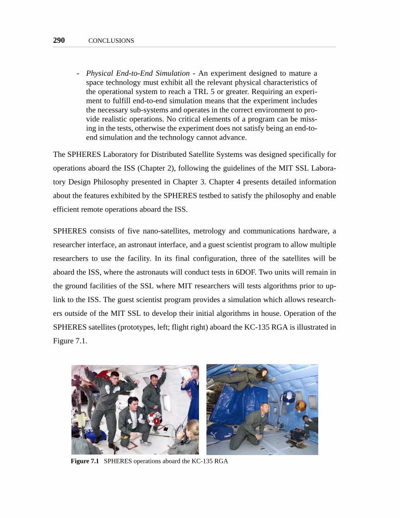
290 CONCLUSIONS
- Physical End-to-End Simulation - An experiment designed to mature aspace technology must exhibit all the relevant physical characteristics ofthe operational system to reach a TRL 5 or greater. Requiring an experi-ment to fulfill end-to-end simulation means that the experiment includesthe necessary sub-systems and operates in the correct environment to pro-vide realistic operations. No critical elements of a program can be miss-ing in the tests, otherwise the experiment does not satisfy being an end-to-end simulation and the technology cannot advance.
The SPHERES Laboratory for Distributed Satellite Systems was designed specifically for
operations aboard the ISS (Chapter 2), following the guidelines of the MIT SSL Labora-
tory Design Philosophy presented in Chapter 3. Chapter 4 presents detailed information
about the features exhibited by the SPHERES testbed to satisfy the philosophy and enable
efficient remote operations aboard the ISS.
SPHERES consists of five nano-satellites, metrology and communications hardware, a
researcher interface, an astronaut interface, and a guest scientist program to allow multiple
researchers to use the facility. In its final configuration, three of the satellites will be
aboard the ISS, where the astronauts will conduct tests in 6DOF. Two units will remain in
the ground facilities of the SSL where MIT researchers will tests algorithms prior to up-
link to the ISS. The guest scientist program provides a simulation which allows research-
ers outside of the MIT SSL to develop their initial algorithms in house. Operation of the
SPHERES satellites (prototypes, left; flight right) aboard the KC-135 RGA is illustrated in
Figure 7.1.
Figure 7.1 SPHERES operations aboard the KC-135 RGA
Thesis Summary 291
The SPHERES features to fulfill the MIT SSL Laboratory Design Philosophy are:
• Facilitate the Iterative Research Process
- Multi-layered operations plan - The SPHERES operations plan directlyaccounts for the need to conduct iterative research. It provides scientistswith multiple steps to incrementally increase the fidelity of their tests,while always ensuring that complete iterations are possible. The need forefficient data collection and ability to update the experiments and/orhypothesis are accounted for at every step.
- Continuous visual feedback - Visual observation of the experiments isavailable at all steps. In most cases where experiments are conducted inground-based facility the scientist can directly observe the tests. All ISSmissions will be recorded; the video will be made available to scientistswithin a few days of the test.
- Families of tests - The SPHERES software allows scientist to program alarge number of tests into each of their programs to be used in a test ses-sion. In this manner, scientists can have ready several experiments whichincrementally demonstrate more features of their algorithms, even beforethe first test. As successful experiments are conducted, the operators canconduct more complex tests, allowing a single session to substantiallyadvance knowledge of a technology.
- Easy repetition of tests - The hardware and software have been designedto allow quick repetitions of tests. Ground-based experiments can be re-started by simply positioning the satellites and using a one-key command.ISS experiments require that the satellite be positioned and then enabled,followed by two step process to ensure the astronaut is ready for the testto start.
- Direct link to ISS data transfer system - By using a direct link to the ISSdata transfer system, the SPHERES operational plan minimizes the lagfor scientists to obtain the collected data. It also simplifies the operationsneeded to upload new programs to the ISS facilities.
- De-coupling of software from NASA safety controls - Software that iscontrolled by NASA requires lengthy reviews before being deployed tothe ISS. By not requiring safety reviews, SPHERES allows scientists tomake any modifications necessary and upload them to the ISS efficiently.
• Support of Experiments
- Data Collection and Validation Features
Layered metrology system - The SPHERES metrology system pro-vides both high-frequency inertial measurements and low-frequency

292 CONCLUSIONS
absolute measurements to provide scientists with the necessary data todetermine the full state of a 6DOF satellite.
Flexible communications: real-time & post-test download - The com-munications mechanism allows scientists to define the amount of datathey need. If the real-time bandwidth is not sufficient, scientists candownload large amounts of data after a test has finished.
Full data storage - To minimize the effects of errors during wirelesstransmission, all the data received by the control laptop is stored intact.While the interfaces process some of that data to show information tothe operators and scientists, all of the data is available for post-pro-cessing.
32 bit floating point DSP - The use of a 32-bit floating point DSP pro-vides scientists with high precision data and quick calculations to meetthe precision needs of their research.
- Redundant communications channels - While the use of two communica-tions channels is directly related to creating an end-to-end simulation, italso increases the reliability of the system since the two channels areinterchangeable.
- Test management & synchronization - Tests with SPHERES can berepeated easily by using the test management software, part of the imple-mentation to support families of tests. The software also synchronizes allthe satellites in a multi-unit test.
- Location specific GUI’s - SPHERES provides two separate interfaces:one for use in ground-based facilities, where the researchers are likely tobe the operators, and one for ISS research, where astronauts are the oper-ators. The use specific interfaces allows scientist maximum observabilityby providing real-time state and debug information in ground-based oper-ations. The ISS interface provides astronauts with the information neces-sary to understand the objectives of a test and to determine the state of thesatellites at all times.
- Re-supply of consumables - The ability to re-supply consumables allowstests to be repeated multiple times to collect sufficient data. It creates arisk-tolerant environment because the scientist can design their experi-ments to push the limits of their algorithms knowing that an error in thetests will not result in the end of the mission due to depletion of all con-sumables. Further, it enables supporting extended investigations.
- Operations with three satellites - The use of three satellites creates redun-dancy for a large number of DSS experiments which require only one ortwo satellites to demonstrate the technology (e.g., docking, tethers).

Thesis Summary 293
- Software cannot cause a critical failure - The design of the satellitesguarantees that the software cannot cause a critical failure of the facilities,such that scientists can program any algorithms, regardless of howaggressive it is, enhancing the risk-tolerant environment of SPHERES.
• Support Multiple Investigators
- Guest Scientist Program - The SPHERES Guest Scientist Program pro-vides scientists with several tools to support their research both at theirhome locations and remotely. Specifically, the GSP provides:
Information Exchange - A clearly defined data path for scientists tocollect the data. Further, members of the SPHERES team can providesubstantial feedback when operations are conducted at the MIT SSLwithout the scientists.
SPHERES Core Software - The core software of SPHERES has beendesigned with modularity and simple interfaces in mind. It provides allthe basic functions to control the satellites, while allowing scientists toprogram only those parts they are most interested in (e.g., metrology,control, or autonomy).
GSP Simulation - The GSP simulation allows scientists to predictresults of their experiments at their home location.
Standard Science Libraries - These libraries provide scientists withseveral routines to simplify the development of their algorithms. Sci-entists can utilize math, metrology, and control functions developed bythe SPHERES team.
- Expansion port - The SPHERES Expansion Port fulfills the need for sci-entists to utilize custom hardware for their specific science goals.
- Portability - The facilities required to operate SPHERES are highly porta-ble, allowing their operation in a multitude of facilities, including at thehome locations of several scientists and special environments such asNASA’s RGA and MSFC’s Flat Floor. This allows multiple scientists toconduct ground-based tests in the environment that best meets theirneeds.
- Schedule flexibility - The schedule to conduct research aboard the ISS hasbeen set at periodic intervals of two weeks. While that time cannot bereduced, the SPHERES team is able to manage that time so that scientistscan take more time to analyze their data.
• Reconfiguration and Modularity
- Generic satellite bus - The SPHERES team identified the generic equip-ment required for research on DSS algorithms and developed the satel-lites to represent a generic satellite bus. In this manner, the satellites can

294 CONCLUSIONS
be used to model the operations of a 6DOF satellite representative ofstandard space missions.
- Science specific equipment: on-board beacon and docking face - As anexample of specific equipment, and to fulfill the original requirements ofthe SPHERES project, the satellites provide an on-board beacon and adocking face to demonstrate docking technologies.
- Generic Operating System - The core software not only provides withmodular interfaces and simple API’s, it also creates a generic real-timeoperating system for dynamics and controls experiments similar to com-mercially available RTOS’s (based on a COTS RTOS).
- Physical Simulation of Space Environment
Operation with three units - The operation with three units aboard theISS allows SPHERES to model the exact operations of mission thatutilize one, two, or three satellites which constitutes a substantial por-tion of DSS research. Further, operations with three satellites modelsthe essential complexity of missions that utilize more units.
Operation in 6DOF - SPHERES is able to simulate the space environ-ment with 6DOF operations aboard the ISS.
Two communications channels - The use of two communicationschannels in SPHERES directly models distributed satellite systemswhich are expected to utilize at least one channel for inter-satellitescommunications and one channel for satellite-to-ground communica-tions.
- Software interface to sensors and actuators - While sensors and actuatorscan be added via the expansion port, SPHERES allows scientists to definetheir own software interfaces to sensors and actuators. In this manner, ascientist can model a sensor or actuator representative of the operationalmission they are researching (of lower bandwidth than the sensors andactuators available in SPHERES).
- Hardware expansion capabilities - Hardware elements can be added tothe SPHERES satellites via two different locations: the docking port sup-ports passive elements, while the expansion port supports active ele-ments. This allows scientists to develop hardware which better representsthe operational mission.
- FLASH memory and bootloader - To enable software reconfiguration acustom bootloader was developed. The bootloader allows the full soft-ware of a SPHERES satellite to be reprogrammed and stored in FLASH.This enables software changes to range from simple corrections to algo-rithms to completely new hypothesis.

Thesis Summary 295
After development of the SPHERES Laboratory (Chapter 4), it was possible to review the
different ways to fulfill the MIT SSL Laboratory Design Philosophy (Chapter 3) for a
project specifically intended to operate aboard the International Space Station (Chapter 2).
The lessons learned resulted in the development of seven design principles for micrograv-
ity laboratories for space technology maturation. These principles, based on the funda-
mentals of the scientific method, collaborative research, and existing resources of the ISS,
apply to laboratories beyond the areas covered in the MIT SSL Laboratory Design Philos-
ophy by identifying those traits that are almost always true of all laboratories, as required
by the definition of a principle. The seven principles are:
• Principle of Iterative Research - A laboratory must enable scientists to con-duct iterative research through repetition of experiments to obtain sufficientdata; provide the capability for scientists to analyze that data and compare itwith predicted results while on a flexible schedule; and allow reconfigura-tion of the facilities to allow for changes in experiments and hypothesis.
• Principle of Enabling a Field of Study - To enable research in a field ofstudy, it is almost always true that a laboratory needs to support multiple sci-entists. This includes the need to provide: the ability for scientists to createmodels and analyze data in their home location; simple operational inter-faces; and efficient data transfer mechanisms.
• Principle of Optimized Utilization - This principle calls for the correct utili-zation of the special resources available aboard the ISS in such a way thatthey add value to the mission. The use of these facilities should not be con-sidered a cost to the mission. The principle identifies five special resources:crew, power, long-term experimentation, and a benign environment/atmo-sphere.
• Principle of Focused Modularity - The facilities of a laboratory almostalways include common parts that can be used by a wide range of applica-tions within the field of study of the laboratory. Those parts, the genericequipment, should be identified and designed in a modular fashion so thatthey can be utilized by as yet unforeseen research.
• Principle of Remote Operation & Usability - Because operations aboard theISS occur in a remote environment where it is practically impossible for theresearch scientist to be present in the operational environment, a laboratoryfor research aboard the ISS must provide tools and information to conducteffective runs of experiments, while the scientists need efficient access todata obtained from the experiments for analysis. Ultimately, the operatorshould become a virtual extension of the scientists aboard the ISS.

296 CONCLUSIONS
• Principle of Incremental Technology Maturation - Utilizing the ISS shouldallow technology maturation to TRL 5 or TRL 6 with the risk and costincreasing incrementally rather than in steep jumps. Successful use of theISS should allow operational missions with a lower total cost and risk thandeployment of the mission directly from ground-based tests.
• Principle of Requirements Balance - For a laboratory to succeed, the require-ments which arise from the previous principles must be balanced, withoutone single requirement driving the majority of the cost and effort in develop-ment of the mission. The hard requirements, which directly affect the abilityto succeed in the mission, must drive the mission efforts. Soft requirements,desired features not directly affecting the success of the mission, should onlybe implemented when they do not cause the mission to break its constraintsand do not contradict any hard requirements.
To enable scientists to use the design principles when developing a new laboratory, a
design framework is presented. The framework involves a four-step iterative process.
First, the scientist must identify the field of study covered by the laboratory. Next the sci-
entist can determine the functional requirements by designing the laboratory such that it
facilitates the iterative research process, enables incremental technology maturation, and
utilizes the resources of the ISS correctly. This design can then be refined by identifying
the modularity of the system which enhances its capabilities, but does not hinder the abil-
ity to satisfy all the mission objectives. The design must also consider the need to support
remote operations. The fourth step is to identify the hard and soft requirements, ensure
that the hard requirements drive the mission, and then iterate on the design to ensure that
the requirements use a balanced amount of cost and effort.
An evaluation framework for members of the proposed NGO that will manage research
activities aboard the ISS is also presented. This framework presents guidelines for an
NGO evaluator to determine the effective use of the ISS while taking into account the suc-
cess of the mission and the achievement of technology maturation.
Chapter 6 presents the results from operations of the SPHERES laboratory up to date and
assesses the laboratory through the design and evaluation frameworks. SPHERES cur-
rently supports multiple research programs, including: mass property identification,

Thesis Summary 297
autonomous rendezvous and docking, TPF formation flight maneuvers, TPF multi-stage
control, tethered formation flight, and the Mars orbit sample retrieval (MOSR) program.
The first three programs are scheduled to be studied during the first phase of ISS research,
while the later three programs will require delivery of new hardware to the ISS. The
results to date include tests at the MIT SSL, NASA’s RGA, and MSFC’s Flat Floor. Tests
at the MIT SSL have included formation flight algorithms and communications, docking
control, mass ID, fault detection identification and recovery, tethered formation flight, and
tests for MOSR. Five week-long campaigns aboard NASA’s RGA (KC-135) consisted of
tests on metrology (inertial and global), single satellite 6DOF controls, formation flight,
docking, mass system ID, thruster ID, tracking, TPF maneuvers, and distributed control
algorithms. The two week-long campaigns at the MSFC Flat Floor consisted of TPF for-
mation flight, docking, and tethered tests.
The review of these operations and results provide the necessary information to evaluate
the design of SPHERES utilizing the design framework; the existing design can be consid-
ered a first iteration of the design process, while this evaluation provides guidelines for
further iterations. The review of the SPHERES design based on the design framework pro-
vides the following conclusions:
• Step 1 - Identify a Field of StudyFor SPHERES to obtain a benefit from supporting multiple investigators, itmust allow research in at least five of the research areas identified withinDSS. These include specific missions (docking and rendezvous, formationflight, separated spacecraft telescopes, tethered spacecraft and sample cap-ture) and several areas of study (metrology, control, autonomy, artificialintelligence, communications, and human machine/interfaces). The first ISSmission of SPHERES is scheduled to conduct research on metrology, con-trol, and autonomy algorithms. These will be specifically applied to dockingmissions and TPF formation flight. Future missions will support tetheredspacecraft and sample return, as well as artificial intelligence programs. It isunclear if SPHERES will be able to support separated spacecraft telescopeand human machine/interfaces research aboard the ISS. Therefore,SPHERES does allow study in a sufficient number of research areas.
• Step 2 - Determine Functional Requirements

298 CONCLUSIONS
The SPHERES laboratory closely follows the guidelines of the Principle ofIterative Research. The metrology and communications systems provide suf-ficient data collection and transfer features to facilitate iterative research.SPHERES clearly allows not only repetition of experiments, but also modifi-cation of both the experiments and the hypothesis. The SPHERES operationsplan has demonstrated great flexibility. Not only has iterative research beenconducted at the MIT SSL, but also at two remote facilities. At all locations,the SPHERES operations plans work to minimize the overhead time to col-lect data and update modifications. Each of the facilities has been used tosuccessfully accomplish iterations.SPHERES obtains substantial value from the correct use of most of theresources available at the ISS. SPHERES slightly under utilizes crew time,but the benefits obtained from its use greatly enhance the risk-tolerant envi-ronment, its ability to facilitate the iterative research process, and providesubstantial feedback to scientists. The total power of SPHERES is minimal,at only approximately 50W for the complete system; but because it does notuse ISS power sources, it obtains no value from that resource of the station.The correct use of telemetry, with flexible download data rates and limiteddata sizes, allow it to minimize data transfer times and maximize the capabil-ities obtained from communications. The duration is considered slightlyshort, although well within the expected lifetime of an ISS mission. Lastly,SPHERES utilizes the ISS environment to a large extent; reducing its devel-opment and operational costs substantially, while ensuring a risk-tolerantenvironment.SPHERES enables the maturation of metrology, controls, and autonomyalgorithms implemented through software to reach TRL 6. The satellites pro-vide the necessary understanding of the interactions between the sub-sys-tems of a satellite through empirical tests under stressful operatingconditions. But the facilities do not allow maturation of hardware technolo-gies to TRL 6 unless these hardware elements can be operated through theSPHERES Expansion Port and the resources exist to deliver them to the ISS.Only a limited number of missions (those of the same scale and properties asSPHERES) can utilize the laboratory to advance to TRL 7.
• Step 3 - Refine DesignThe SPHERES satellites as a whole provide modularity and reconfigurationby being identical satellites, interchangeable with each other, and by usingthe docking port and expansion port to allow reconfiguration. The satellitesub-systems, on the other hand, do not provide modularity since, in mostcases, that would violated the 1 MLE mass/volume constraint for the systemwith little added value. The software sub-system is highly reconfigurableand modular as a direct result of the mission goals. The metrology beaconsare modular in their ability to be interchanged and reconfigured with ease to

Thesis Summary 299
provide accommodate different operational environments of the globalmetrology system. The laptop transceiver enables the use of the SPHERESfacilities through any standard PC serial port at many locations.To satisfy the Principle of Remote Operations and Usability, SPHERES pro-vides two separate interfaces to operate the facilities: a ground-based inter-face and an ISS interface. Further, the SPHERES simulation was developedto account for the remote location of scientists who are not members of theSPHERES team. The ground-based interface was designed for operations atthe MIT SSL, NASA RGA, MSFC Flat Floor, and other facilities where theoperators are either the researchers and/or members of the SPHERES team.This interface provide simple, single-key-stroke, operations for all commontasks and incorporating program upload directly into the interface. The avail-ability of optional windows with real-time state and debug data allows theinterface to provide relevant data when the operators are the research scien-tist. The interface does require the operator to initiate data storage, thereforecreating the potential situation where data is not stored due to operator error,but to minimize that the interface clearly indicates when data is being saved.Further, the SPHERES team developed several Matlab functions to analyzethe data. The SPHERES simulation and the information provided with theGuest Scientist Program allows the scientist to create models of their experi-ments and compare the information.The ISS interface utilizes several steps to ensure the operator selects the cor-rect program and test and is aware of the expected results of each experi-ment. The ISS interface stores data immediately upon starting. Regardless ofthe operator’s actions, the program will save all outgoing and incoming rawdata, ensuring the data is safe regardless of the operator’s actions. The flightGUI presents information to the operator to always be aware of the state ofthe satellites through a status bar. Descriptions of the tests are presented toallow the operators to know expected results and make decisions on the testperformance. By providing sufficient details on the test, the interfacereduces the dependency of real-time communications with the researcher.Further, the interface presents a questionnaire to the astronaut at the end ofeach test, requiring the astronaut to provide feedback The astronaut is alsoallowed to enter notes freely after the questionnaire effectively creating anelectronic laboratory notebook.
• Step 4 - Review Requirements and DesignA total of 31 system-level functional requirements were identified for thisiteration of the SPHERES laboratory design. Of those 21 are hard require-ments and 10 soft requirements. Further review into the efforts needed toimplement the requirements resulted in the following conclusions.
- The requirements relevant to 6DOF operations did not require substantialtrade-off’s in the implementation of the sub-systems.

300 CONCLUSIONS
- The hard requirements to operate aboard the ISS and to facilitate itera-tions by allowing the collection of substantial data and enabling recon-figuration forced trade-offs in the following implementation decisions:
One-time Use Batteries - The need to operate aboard the ISS and meetsafety requirements prevented the use of rechargeable batteries whichwould have provided benefits to iterative research, long-term experi-mentation, and modularity.
Custom Metrology System - The decision to develop a custom metrol-ogy system resulted in the investment of too many resources and effortto this sub-system, while the resources allocated to other sub-systems(such as propulsion and the expansion port) were not balanced.
Propellant Selection (CO2) - The selection of the propellant correctlybalanced the need to support iterative research and create a representa-tive environment for technology maturation even though it requiredincreased resources to operate aboard the ISS.
Expansion Port - The development of the expansion port towards theend of the program implementation prevented sufficient resources tobe used in developing a simpler interface. Still, the port has allowedthe development of several expansion items to increase the researchpossibilities of the facility.
Communications Channel Frequency - The need to operate aboard theISS without creating any bureaucratic issues due to safety concerns byNASA required the selection of wireless communications in the900MHz range, which is limited to 56.6kbps, rather than the use of802.11b hardware which allows over 1Mbps. This trade-off was nec-essary to ensure the iterative research process is efficient when usingSPHERES.
- The soft requirements did not account for substantial effort or use ofresources, since the most important design decisions were not driven byrequirements not essential to the mission.
The current iteration of the SPHERES laboratory design meets the principles to a large
extent. The facility enables research on multiple areas within Distributed Satellite Sys-
tems. The facilities enable iterative research with few limitations, minimal overhead, and
flexible schedules. The iterative nature of the research in a microgravity environment
allows technologies to mature incrementally to TRL 5 or TRL 6. SPHERES achieves this
by utilizing many of the resources available aboard the ISS. Both the software and hard-
ware allow reconfiguration, although hardware changes do require delivery of the new

Thesis Summary 301
items to the ISS. The software is highly modular, allowing scientists to work only on their
specific area of study. Overall, the resources and effort put into the implementation of the
features are correctly balanced.
A new iteration of SPHERES would consider utilizing rechargeable batteries to benefit
the iterative research process by allowing more repetitions, ensure long-term experimenta-
tion, and lower its need for launch mass and storage volume aboard the ISS. If the metrol-
ogy system were still in the design stages, the selection to use a custom system would be
revised; since it is already implemented, the program should ensure that substantial
metrology research occurs to warrant the amount of resources used to implement the sub-
system. Lastly, the expansion port should be reviewed to provide better interfaces that
allow easier development of expansion items.
Finally, the evaluation framework was applied to SPHERES. An ISS evaluator concen-
trates on the correct utilization of ISS resources, the ability to demonstrate technology
maturation, and the scope of the program. The review of SPHERES concludes that:
• SPHERES enables iterative research by allowing repetitions, experimentmodification, and hypothesis modifications. Reservations exist due to theconsumables required for operations.
• SPHERES has been correctly designed to support multiple investigatorsconducing research aboard the ISS. The resources necessary from the ISSare acceptable, and the necessary programs exist for efficient data transfer toscientists.
• The utilization of crew, communications, long-term experimentation, andbenign environment resources is acceptable. The crew time is small but pro-vides important benefits to the mission. The use of ISS telemetry systemshas been well incorporated into the program. Long-term experimentation,while limited by consumables, is of the correct length (six months to a year).The benign environment is fully accounted for. SPHERES does not use thepower resources of the ISS correctly, and its design should be reviewed toanalyze the possibility to make better use of this resource.
• SPHERES offers little modularity from the perspective of the ISS. The glo-bal metrology system is the only component which can be easily used byother programs beyond SPHERES. The communications system could pro-vide modularity, but utilizes too much custom hardware. The satellites

302 CONCLUSIONS
enable research by multiple scientists, but cannot be considered modules foruse by other programs independently from SPHERES.
• From the ISS NGO perspective, the SPHERES team has accounted for allthe necessary tools to allow successful remote operations of the SPHERESfacilities, even without real-time communications between the scientists andthe operator.
• SPHERES can allow technology demonstrations to TRL 5 for a large num-ber of programs. TRL 6 can also be achieved, for a limited number of pro-grams, especially if new hardware can be delivered. SPHERES cannot beconsidered a laboratory to demonstrate a technology to TRL 7.
As a result, an ISS NGO evaluator following the evaluation framework would conclude
that SPHERES can operate aboard the ISS, but several reservations exist which should be
addressed. The long-term experimentation is greatly challenged by the consumables
required in SPHERES, and steps should be taken to minimize the dependence on consum-
ables. Specifically, the use of rechargeable batteries should be considered. Further, the
SPHERES team should develop contingency plans which detail operations and science
benefits from the use of SPHERES without propellant. While SPHERES provides little
modularity for the ISS, any changes to the modularity would be too large and costly for
the program; therefore, the evaluator should not propose the changes, but should consider
the limited modularity when evaluating other projects. None of the reservations are sub-
stantial enough to preclude the use of SPHERES aboard the ISS; to the contrary,
SPHERES fulfills a substantial part of the design principles. It utilizes the crew of the ISS
wisely, allowing astronauts to become scientists in space. Further, it opens the use of the
ISS to multiple scientists who would otherwise not be able to conduct research in a micro-
gravity environment. Therefore, the SPHERES laboratory enhances the science capabili-
ties of the ISS allowing it to better achieve its primary objective: to provide and “Earth
orbiting facility that houses experiment payloads, distributes resource utilities, and sup-
ports permanent human habitation for conducting research and science experiments in a
microgravity environment.” [NASA, 1998]

Contributions 303
7.2 Contributions
The research presented in this thesis extracts the fundamental characteristics that a labora-
tory must exhibit and condenses them into a set of design principles for the development
of space technology maturation laboratories. The principles also derive from the lessons
learned in the design, implementation, and operation of the SPHERES laboratory, which
provides a special research environment for the maturation of technologies related to dis-
tributed satellite systems. The following are the specific contributions identified from the
research:
• Identified the fundamental characteristics of a laboratory for space technol-ogy maturation and formalized the features required in the design of a labo-ratory to exhibit said characteristics.
- Identified the need for a laboratory to support iterative research utilizingthe definition of the scientific method. While laboratories are continu-ously created at research institutions, no previous literature specificallyaddresses the need for a laboratory to enable every step of the scientificmethod. This thesis formally calls for a laboratory to support iterativeresearch, including development of a hypothesis, design and operation ofexperiments, data collection and analysis, and the ability to modify thehypothesis until the desired performance is met.
- While literature on the Design of Experiments (DOE) emphasizes theneed to collect data at operationally interesting points, this thesis goes astep beyond DOE towards the development of a laboratory that allowsrepetitions of experiments at all data points. A laboratory reduces thedependency on DOE techniques to minimize the number of experimentruns.
- The review of existing research facilities, definition of a laboratory, andcollaborative science identifies the need for a laboratory to enableresearch of a field of study by supporting multiple scientists. Given therestricted access to a space environment, projects which support spacetechnology maturation must enable research of a field of study.
- Determined the use of the International Space Station as a location whichhelps reduce the major challenges of space technology research: risk,complexity, cost, remote operations, and visibility.
• Established a set of principles to guide the design of research laboratories forspace technology maturation aboard the International Space Station.

304 CONCLUSIONS
- The principles address the need to facilitate the iterative research process,enable a field of study, and enable incremental technology maturation,coupled with the need to account for remote operations aboard the Inter-national Space Station.
Enables the use of the ISS to incrementally mature technologies insuch a manner the total risk and cost of a mission can be reduced.
The principles are based on a comprehensive review of ISS research,existing resources, and programed upgrades to ensure they account forthe correct utilization of the station.
- Developed a design framework for application of the principles byresearch scientists.
- Developed an evaluation framework which can be used to respond in partto the call by the National Research Council to define the functions of anon-governmental organization which manages the science aboard theInternational Space Station.
The application of these principles in the design of new laboratoriesfor research aboard the ISS can result in an expanded base of scientistswho can conduct research under the microgravity environment of theISS.
Calls for a change in attitude towards the use of resources aboard theInternational Space Station: rather than treat the use of those resourcesas a cost which must be minimized, the resources should be treated asadded value, which must be maximized.
• Designed, implemented, and operated the SPHERES Laboratory for Distrib-uted Satellite Systems.
- Provides a facility for multiple researchers to advance metrology, control,and autonomy algorithms in a microgravity environment able to meet therequirements for TRL 5 or TRL 6 maturation.
- Demonstrates the implementation of miniature embedded systems to sup-port research by multiple scientists through the creation of a flexibleembedded system which allows implementations of multiple types ofalgorithms.
Developed a real-time operating system with modular and simpleinterfaces for use by multiple scientists.
- Demonstrates the ability to create generic equipment while enablingfuture expansion through both hardware and software.
- Approaches virtual presence of the scientists in a remote location by pro-viding the necessary interfaces to present the operator with the necessary

Future Work 305
knowledge to be an integral part of the research process. Further, it cre-ates a laboratory environment by allowing astronauts to provide feedbackto the scientists.
7.3 Future Work
The recommendations for future work concentrate on two main areas: further develop-
ment of the design principles and operations of the SPHERES laboratory. While the con-
cepts behind the laboratory design principles have been reviewed with more than twenty
experiments conducted during Expedition 6 aboard the ISS, the actual application of the
principles lacks data points. Validation of the design principles by their application and
evaluation in several new programs would provide the necessary validation. The design
framework provides a few initial quantitative measures to utilize in the application of the
principles. These measures are extracted from available information about product plat-
forms and the review of the International Space Station existing capabilities. These quan-
titative models should be validated with new data as experiments are designed following
the guidelines of the design principles.
These principles concentrate on the creation of the engineering and technical aspects of
the program. This thesis does not introduce the need to also provide financial support for
the laboratories, as it assumes that a well designed laboratory will have high demand
within the scientific community. A parallel study, which considers both the development
and maintenance costs of these type of laboratories should be created.
The ability of scaled experiments aboard the ISS to demonstrate the maturity of space
technologies depends directly on the ability of scientists to prove that these models are
representative of actual mission. To this end, research should be conducted to develop a
set of scaling laws, equivalent to those used in aeronautical engineering when testing with
wind-tunnels, which enable scientists to scale the results of models used aboard the ISS to
for application in full-scale space missions.

306 CONCLUSIONS
Due to circumstances outside the control of the SPHERES program, its operations aboard
the ISS have not taken place yet. Therefore, future work must evaluate ISS operations to
corroborate the expected results presented in the evaluation of SPHERES in Chapter 6.
While the usefulness of the Guest Scientist Program has been demonstrated through multi-
ple ground-based programs, the ability of SPHERES to facilitate the iterative research
process through complete ISS iterations are yet to be demonstrated. Future work must sup-
port or refute the ability of SPHERES to minimize the overhead time and maximize the
science time available during each research cycle. The lack of demonstrations in a space
environment has also prevented any algorithms developed with the use of SPHERES to
mature to TRL 5 or TRL 6. Therefore, continued research is necessary to confirm that
SPHERES can help mature technologies to those levels.
Work should also be performed to enhance the capabilities of the SPHERES facilities:
• The SPHERES metrology system requires continued research to ensure itcan provide the necessary accuracy and precision in a 3D environment.While the system has been tested and its capabilities demonstrated in 2Denvironments, 3D tests have been limited to operations aboard the reducedgravity airplane (KC-135) and limited tests at the MIT SSL.
• Future work to upgrade the software capabilities of SPHERES is also recom-mended. The current software concentrates on the ability to test metrology,control, and autonomy algorithms. Future work should allow scientists totest different communications protocols and test the real-time requirementsof operating systems for distributed satellite systems.
• As clearly indicated by the frameworks, the SPHERES satellites should beupgraded to use rechargeable batteries.
Future research to be conducted with the SPHERES laboratory already includes tethered
formation flight, multi-stage optical formation flight telescopes, and the Mars orbital sam-
ple return. The development of active docking ports is also planned. An area missing to
research with SPHERES is human/machine interfaces. SPHERES provides the unique
capability for humans aboard the ISS to control a 6DOF satellite with minimal risks in a
full microgravity environment. This enables the creation of training environments where
humans can use advanced interfaces (e.g. special joysticks) to control 6DOF satellites.

Concluding Remarks 307
SPHERES allows research on the human factors engineering aspects (e.g. design of the
joysticks) as well as actual training of astronauts for general or specific missions once an
interface has been selected. The possibility for the SPHERES satellites to support astro-
naut activity aboard the ISS via the use of wireless video should also be considered.
7.4 Concluding Remarks
This thesis concentrates on the development of seven design principles for the design of
space technology maturation laboratories to operate aboard the International Space Sta-
tion. The research required substantial background information on previous space pro-
grams, other microgravity facilities, other remote facilities, the scientific method,
collaborative research, and NASA Technology Readiness Levels. The resulting principles
address the most basic mission of the International Space Station: to conduct research in a
microgravity environment.
But all this research would not have been complete without the lessons learned from the
design, implementation, and operation of the SPHERES testbed. The words design, imple-
mentation, and operation appear multiple times in this thesis. They are the force behind
the development of the SPHERES prototype system: teaching undergraduate students the
complete design process in the form of CDIO - conceive, design, implement, operate. The
road traversed through the development of SPHERES was so rich with information on the
requirements of a laboratory because the teaching staff was learning together with the stu-
dents. While staff could provide simple implementation answers, the staff continuously
evaluated the why’s of the design; this knowledge represents the lessons learned from
SPHERES which resulted in the development of the design principles. Therefore, the
work in this thesis represent the knowledge acquired not only by the author, but also by
thirteen undergraduate students at MIT, over a dozen staff members, and the several guest
scientists who participate in the SPHERES Guest Scientist Program.
The laboratory environment created by SPHERES will provide many scientists with the
ability to demonstrate their algorithms in space, something they would not be able to do

308 CONCLUSIONS
otherwise. Expansion items will reach the ISS so that the SPHERES facilities can better
represent new missions. This will allow the study of the origins of our galaxy through mis-
sions such as TPF, make autonomous re-supply of spacecraft a reality, and even enable the
development of technologies, such as tethers, to permit extended human travel into space.

REFERENCES
[Adler, 2004] Adler, N, Shani, A.B., Styhre, A, "Collaborative Research in Organiza-tions", SAGE Publications, London, 2004
[Amir, 1999] Amir, A R, Baroni, G, Pedrocchi, A, Newman, D J, Ferrigno, G, Pedotti, A,"Measuring astronaut performance on the ISS: advanced kinematic and kineticinstrumentation", Proceedings of the 16th Instrumentation and MeasurementTechnology Conference, IEEE, May 1999, Vol 1, pp 397 - 402
[Amir, 2000] Amir, A R, Newman, D J, "Research Into the Effects of Astronaut Motionon the Spacecraft: a Review", Acta Astronautica, Elsevier Science Ltd, GreatBritain, 2000, Vol 47, No 12, pp 859-869
[Antony, 2003] Antony, Jiju, "Design of experiments for engineers and scientists", But-terworth-Heinemann, Burlington MA, 2003
[ARF, URL] Antarctic Research Facility, Florida State University "Home"
• http://www.arf.fsu.edu/
[Ashley, 2004] Ashley, M.C.B., Burton, M.G., Lawrence, J.S. & Storey, J.W.V.,"Robotic telescopes on the Antarctic plateau", School of Physics, University ofNew South Wales, Sydney, Australia, 2004
[Astronautix] Encylopedia Astronautica, "Salyut", astronatuix.com
• http://www.astronautix.com/project/salyut.htm
[BAS1] "Globa Science in the Antarctic Context", British Antactic Survey, Cambridge,UK
[BAS2] "Antarctic Science in the Global Context", British Antarctic Survey, Cambridge,UK
[Beach, 1992] Beach, David P, Alvager, Torsten K E, "Handbook for Scientific andTechnical Research", Prentice Hall, Englewood Cliffs JH, 1992
[Beichman, 1999] Beichman, C A, Woolf, N J, and Lindensmith, C A, “The TerrestrialPlanet Finder (TPF): A NASA Origins Program to Search for Habitable Planets,”JPL Publication 99-3, 1999
[Bemporad, 2002] Bemporad, A, Borrelli, F, and Morari, M, “Model Predictive ControlBased on Linear Programming - The Explicit Solution,” IEEE Transaction onAutomatic Control, Vol. 47, No. 12, pp. 1974-1985, December 2002
309

310 REFERENCES
[Berkovitz, 2003] Berkovitz, Dustin, Kong, Edmund, Miller, David W, "System Identifi-cation of the SPHERES Autonomous Rendezvous and Docking Testbed", AIAASpace 2003 Conference, Long Beach CA, 2003
[Belew, 1977] Belew, Leland F, "Skylab, Our First Space Station", NASA Scientific andTechnical Information Office, Washing DC, 1977
[Blaurock, 1999] Blaurock, C, Kenny, S, Miller, D, Yung, J, “Nonlinear Modeling andControl for the Middeck Active Control Experiment Reflight,” AIAA SpaceTechnology Conference & Exposition, AIAA 99-4589, Albuquerque, NM, Sept.28-30, 1999
[Burrough, 1998] Burrough, B, "Dragonfly: NASA and the Crisis Aboard Mir", HarperCollins Publishers, New York, NY, 1988
[Burton, 2004] Burton, M.G., "Astronomy in Antarctica", in Organizations and Strate-gies in Astronomy, Volume 5. Series editor Andre Heck, Kluwer, 2004
[Campbell, 1995] Campbell, M E, Grocott, S C O, How, J P, Miller, D W, Crawley, E F,"Verification procedure for on-orbit controllers for the MIT Middeck ActiveControl Experiment", Proceedings of the American Control Conference, SeattleWA, June 1995, Vol 5, pp 3600 - 3605
[Campbell, 1999] Campbell, M E, How, J P, Grocott, S C O, and Miller, D W, “On-OrbitClosed-Loop Control Results for the Middeck Active Control Experiment,”AIAA Journal of Guidance, Control, and Dynamics, Vol. 22, No. 2, Mar-Apr.1999.
[Chen, 2001] Chen, A, Saenz-Otero, A, Hilstad, M, Miller D, ""Development of Forma-tion Flight and Docking Algorithms Using the SPHERES Testbed", 15th AnnualUSU Conference on SMall Satellites, Utah State University, UT, SSC01-VIIIa,August 13-26, 2001
[Cook, 1997] Cook, H. E., "Product Management: Value, Quality, Cost, Price, Profits,and Organization", Chapman & Hall, London & New York, 1997
[Crawley, 2003] Crawley, Ed, "Introduction to System Architecture: Architecture toValue", Massachusetts Institute of Technology, ESD.34J Lecture notes, January9, 2003, Rev 2.0
[Cunninghman, 1970] Cunningham, R E, Cooper C G, Dilham, H B, et al, "Ocean Engi-neering Research Ship Systems", Massachusetts Institute of Technology, ReportNo 70-9, vol 1, Cambridge MA, 1970
[Davenport, 1999] Davenport, S, Davies, J, Grimes, C, "Collaborative Research Pro-grammes: Building Trust from Differences", Technovation v19, Pergamon, 1999

REFERENCES 311
[Durham, 2004] Durham, H J, "ISS Program Infrastrure Upgrades to Enhance ScienceReturn: Current, Planned & Potential", 2004 IEEE Aerospace Conference, Mon-tana, USA, IEEAC paper #1083
[deSouza, 2004] de Souza, C R B, Redmiles, D, Cheng, L T, et al, "How a Good Soft-ware Practice Thwarts Collaboration - The Multiple Roles of APIs in SoftwareDevelopment", SIGSOFT ’04, ACM, Newport Beach, CA, Oct 31-Nov 6, 2004
[Elzinga, 1993] Elzing, A, "Changing Trends in Antarctic Research", Kluwer AcademicPublishers, Dordrecht, The Netherlands, 1993
[Emond, 2000] Emond, J, "The Spacelab Accomplishments Forum", NASA, WashingtonDC, 2000
[Enright, 2004] Enright, J, Saenz-Otero, A, et. al., “The SPHERES Guest Scientist Pro-gram: Collaborative Science On the ISS”, IEEE Aerospace Conference 2004, BigSky, Montana, Paper #1296, March 2004
[Ernst, 2003] Ernst, Michael, "Retrospective and Iterative Design", Science of Design:Software-Intensive Systems Workshop, NSF Computer and Information Scienceand Engineering Directorate, University of Virginia, 2003
[Fisher, 1935] Fisher, Ronald A, "The Design of Experiments", Oliver and Boyd, Lon-don UK, 1935
[Gauch, 2003] Gauch, Hugh G Jr, "Scientific Method in Practice", Cambridge UniversityPress, Cambridge UK, 2003
[Graettinger, 2002] Graettinger, C P, Garcia, S, Siviy, J, et al, "Using the TechnologyReadiness Levels Scale to Support Technology Management in the DoD’s ATD/STO Environments", Carnegie Mellon Software Engineering Institute, Pitts-burgh, PA, 2002
[Grocott, 1994] Grocott, S, How, J, Miller, D, MacMartin, D and Liu, K, “Robust Con-trol Design and Implementation on the Middeck Active Control Experiment,”AIAA Journal of Guidance, Control, and Dynamics, Vol. 17, No. 6, pp. 1163-1170, Nov-Dec 1994
[Hablani, 2001] Hablani, H B, Tapper, M, Dana-Bashian, D, “Guidance Algorithms forAutonomous Rendezvous of Spacecraft with a Target Vehicle in Circular Orbit,”Proc. of the AIAA Guidance, Navigation, and Control Conference and Exhibit,A01-37204, AIAA 2001-4393, Montreal, Canada, August 2001
[Hagopian, 1998] Hagopian, J, Maxwell, T, Nahay, E, "NASA/MIR Phase 1: A Lessonin Long Duration Mission Planning and Operations", SpaceOps 98, Tokyo,Japan, paper 2m018, June 1-5, 1998

312 REFERENCES
[Haux, 1982] Haux, G F K, "Subsea Manned Engineering", Baillière Tindall, London,UK, 1982
[Hilstad, 2003] Hilstad, M O, "A Multi-Vehicle Testbed and Interface Framework for theDevelopment and Verification of Separated Spacecraft Control Algorithms",Master's thesis, Massachusetts Institute of Technology, Department of Aeronau-tics and Astronautics, June 2003
[Hilstad, 2003a] Hilstad, M., Enright, J., Richards, A., "SPHERES Guest Scientist Pro-gram Interface Document", MIT Space Systems Laboratory, 2003
[How, 1997] How, J, Glaese, R, Grocott, S, Miller, D, "Finite element model-basedrobust controllers for the middeck active control experiment (MACE)", IEEETransactions on Control Systems Technology, IEEE, January 1997, Vol 5 , Issue1, pp 110 - 118
[Hupfer, 2004] Hupfer, S, Cheng, L, Ross, S, Patterson, J, "Introducing Collaborationinto an Application Development Environment", Computer Supported Coopera-tive Work ’04, ACM, Chicago IL, November 6-10, 2004
[Huxham, 1996] Huxham, C., "Creating Collaborative Advantage", SAGE Publications,London, 1996
[IMBOSS, URL] IMBOSS Documentation
• http://www.rm.iasf.cnr.it/ias-home/IMBOSS/imbossdocs.html
[Intel, 2003] "Intel Research Network: A New Model of Industry-Unversity Collabora-tion", Intel Research and Development, USA, 2003
[JAMIC, URL] Japan Microgravity Center, Page automatically translated from Japanese
• http://www.jasma.info/SisetsuShoukai/JAMIC.html
[Jilla, 2002] Jilla, C, "A Multiobjective, Multidisciplinary Design Optimization Method-ology for the Conceptual Design of Distributed Satellite Systems", Doctoral The-sis, Department of Aeronautics and Astronautics, Massachusetts Institute ofTechnology, Cambridge, MA 2002
[Kraut, 1988] Kraut, R, Egido, C, "Patters of Contact and Communication in ScientificResearch Collaboration", Proceedings of the 1988 ACM conference on com-puter-supported cooperative work, p1-12, Portland Oregon, 1988
[Kong, 2004] Kong, Edmund M C, Saenz-Otero, Alvar, et al, "SPHERES as a FormationFlight Algorithm Development and Validation Testbed: Current Progress andBeyond", 2004 Formation Flight Symposium, Washington DC, September 2004
[Kong, 2004a] Kong, E M C, Hilstad, M O, Nolet, S, and Miller, D W, “Development

REFERENCES 313
and verification of algorithms for spacecraft formation flight using the SPHEREStestbed: application to TPF,” SPIE Astronomical Telescope 2004, Paper No.5491-34, Glasgow, Scotland, June 2004
[Larson, 1992] Larson, Wiley J, Wertz, James R, "Space Mission Analysis and Design",Microcosm Inc, Torrance CA, 1992
[LeGris, 2000] LeGris, J, Weir, R, Browne, G, Gafni, A, Stewart, L, and Easton, S,"Developing a model of collaborative research: the complexities and challengesof implementation", International Journal of Nursing Studies, Volume 37, Issue1, February 2000
[Lindensmith, 2003] Lindesmith, C A (Editor), "Technology Plan for the TerrestrialPlanet Finder", NASA and Jet Propulsion Laboratory, California Institute ofTechnology, JPL Publication 03-007, Rev A, March 2003
[Littler, 1995] Littler, D, Leverick, F, Bruce, M, "Factors Affecting the Process of Col-laborative Product Development: A Study of UK Manufacturers of Informationand Communications Technology Products", Journal of Product Innovation Man-agement, v12-1, p16, January 1995
[Lorenzen, 1993] Lorenzen, Thomas J, Anderson, Virgil L, "Design of Experiments, ANo-name Approach", Marcel Dekker, New York NY, 1993
[Mankins, 1995] Mankins, J, "Technology Readiness Levels", Advanced ConceptsOffice, Office of Space Access and Technology, NASA, April 1995
[Mather, 1998] Mather, J C, et al., “The Submillimeter Frontier: A Space Science Imper-ative,” Astrophysics 1998, astro-ph/9812454
[Matossian, 1996] Matossian, M., "Design for Success: Optimizing the Earth ObservingSystem for Performance and Cost with Managed Risk," Proceedings of the 46thInternational Astronautical Congress, IAF-95-Q.4.05, 1995
[Mead, 1988] Mead, R, "The design of experiments", Cambridge University Press, Cam-bridge UK, 1988
[Merriam-Webster, URL] Merriam-Webster Online Dictionary
• http://www.webster.com/
[Merrill-Sands, 1996] Merril-Sands, D., Sheridan, B., "Developing and Managing Col-laborative Research Alliances: Lessons from a Review of the Literature", Sim-mons Institute for Leadership and Change, Simmons College, Boston, MA, 1996
[Meyer, 1997] Meyer, M, Lehnerd, A, "The power of Product Platforms", The Free Press,New York, 1997

314 REFERENCES
[Miller, 1992] Miller, D W, "The MODE Family of Facility Class Experiments: Con-ducting Cost Effective Engineering Research in the Shirt Sleeve Environment ofthe Middeck," Flight Experiment Technical Interchange Meeting, Monterrey,CA, Oct., 1992
[Miller, 1995] Miller, D W, deLuis, J, Stover G, How, J P, et al, "The Middeck ActiveControl Experiment (MACE): using space for technology research and develop-ment" Proceedings of the American Control Conference, Seattle WA, June 1995,Vol 1, pp 397 - 401
[Miller, 1996] Miller, D. W., et al, "The Middeck Active Control Experiment (MACE):Summary Report", MIT Space Engineering Research Center, June 1996, SERC#7-96
[Miller, 1998] Miller, D W, How, J P, Campbell, M E, Grocott, S C O, Liu, K, Glaese, RM, and Tuttle, T, "Flight Results from the Middeck Active Control Experiment(MACE)," AIAA Journal, Vol. 36, No. 3, March 1998, pp. 432-440
[Montgomery, 1991] Montgomery, Douglas C, "Design and analysis of experiments",Wiley, New York NY, 1991
[Mosher, 2000] Steuer, R E.” Multiple Criteria Optimization: Theory, Computation andApplication”. Wiley, New York, 1986
[Myers, 1996] Myers, J.D.; Fox-Dobbs, C.; Laird, J.; Dai Le; Reich, D.; Curtz, T., "Elec-tronic laboratory notebooks for collaborative research", Proceedings of the 5thWorkshop on Enabling Technologies: Infrastructure for Collaborative Enter-prises, vI., p47-51, 19-21 June 1996
[Myers, 2001] Myers, J, Mendoza, E, Hoopes, B, "A Collaborative Electronic Note-book", Proceedings of the IASTED International Conference on Internet andMultimedia Systems and Applications (IMSA 2001), Honolulu, Hawaii, August13-16, 2001
[NASA, 1998] "International Space Station Familiarization", Mission Operations Direc-torate, Space Flight Training Division, NASA, Houston TX, July 1998
[NASA, 2000] "Science and Technology Research Directions for the International SpaceStation", Office of Life & Microgravity Sciences and Applications, NASA,Houston, TX, January 2001
[NASA, 2000a] "Space Shuttle Program, Payload Bay Payload, User’s Guide", NASALyndon B. Johnson Space Center, Houston TX, NSTS 21492, December 2000
[NASA, 2000b] "ISS User’s Guide - Release 2.0", NASA, Houston TX, 2000

REFERENCES 315
[NASA, 2004] NASA, "ISS Technical Confguration", July 23, 2004
[NASA, 33897] "Experiment Design Requirements and Guidelines, NASA 931KC135A", Aircraft Operations Division, NASA Lyndon B. Johnson Space Cen-ter, Houston TX, AOD 33897, February 2003
[NASA, 33898] "Interface Control Document, NASA 931 KC135A", Aircraft OperationsDivision, NASA Lyndon B. Johnson Space Center, Houston TX, AOD 33898,May 2004
[NASA, 33899] "JSC Reduced gravity Program, User’s Guide", Aircraft Operations Divi-sion, NASA Lyndon B. Johnson Space Center, Houston TX, AOD33899, March2004
[NASA, URL1] NASA, "International Space Station: Science", accessed URLS:
• Home: http://spaceflight.nasa.gov/station/science/index.html
• Expedition 6 Experiments: http://spaceflight.nasa.gov/station/science/experi-ments/exp6_expmt.html
[NASA, URL2] NASA, "Research on Station --- PCG Single-locker Thermal EnclosureSystems":
• http://spaceresearch.nasa.gov/research_projects/ros/pcgstes.html
• http://spaceresearch.nasa.gov/research_projects/ros/pcgstesop.html
[NASA, URL3] NASA Glenn 2.2 Second Drop Tower
• http://microgravity.grc.nasa.gov/drop2/
[NASA, URL4] NASA Space Shuttle Payload Information Source
• http://shuttlepayloads.jsc.nasa.gov/flying/overview/overview.htm
[NASA, URL5] NASA: History of Shuttle-MIR Home Page
• http://spaceflight.nasa.gov/history/shuttle-mir/index.html
[NASA, URL6] NASA NBL Website
• http://www1.jsc.nasa.gov/dx/dx12/
[NASA, URL7] "The Neutral Buoyancy Simulator", NASA Marshall Space Flight CenterFact Sheets
• http://www1.msfc.nasa.gov/NEWSROOM/background/facts/nbs.htm
[NASA, ULR8] "HSF - International Space Station", NASA Human space Flight
• http://spaceflight.nasa.gov/station/index.html

316 REFERENCES
[Newman, 2001] Newman, D J, Amir, A R, Beck, S M, "Astronaut-Induced Distrubancesto the Microgravity Environment o the Mir Space Station", Journal of Spacecraftand Rockets, AIAA, July-August 2001, Vol 38, No 4, pp 578-583
[NMP, 2003] "Technology Readiness Levels for the New Millennium Program", NewMillennium Program, NASA, version 1, May 2003
[NRC, 1999] "Institutional Arrangements for Space Station Research", NationalResearch Council, Washington D.C., 1999
[NRC, 2000] "Engineering Challenges to the Long-Term Operation of the InternationalSpace Station", National Research Council, Washington DC, 2000
[NRC, 2001] "Readiness Issues Related to Research in the Biological and Physical Sci-ences on the International Space Station", National Research Council, Washing-ton DC, 2001
[NRC, 2002] "Factors Affecting the Utilization of the International Space Station forResearch in the Biological and Physical Sciences", National Research Council,Washngton DC, 2002
[NRC PRB] Polar Research Board, "Antarctic Treaty System: An Assessment", NationalResearch Council, Washington DC, 1985
[Nolet, 2004] Nolet, Simon, Kong, Edmund, Miller, David W, "Autonomous dockingalgorithm development and experimentation using the SPHERES testbed", SPIEDefense and Security Symposium, Orlando FL, 2004
[NSTS, XIV] "Space Shuttle System Payload Accommodations", Space Shuttle Customerand Flight Integration Office, NASA, Houston, TX, Rev L.1, 2001
[O’Neill, 1999] O’Neill, J, Wales, R, "CSCA Issues Raised by Mission Control for theInternational Space Station", CSCL 1999, UK
[OPP, URL] Antarctic Science Section, Office of Polar Programs
• http://www.nsf.gov/od/opp/antarct/start.htm
[Pololu, URL] "Micro Dual Serial Motor Controller User’s Guide", Pololu Corporation,Las Vegas, NV
• http://www.pololu.com/products/pololu/0410/smc02b_guide.pdf
[PSI, 2003] "Middeck Active Control Experiment (MACE) and MACE-II", Payload Sys-tems Inc, Cambridge, MA, October 2003
[Penzias, 1973] Penzias, W, and Goodman M W, "Man Beneath the Sea", Wiley Inter-science, New York, 1973

REFERENCES 317
[Portree, 1995] "Mir Hardware Hritage", Information Services Division, Lyndon B.Johnson Space Center, Houston TX, NASA Reference Publication 1357, March1995
[RFM, URL] "RFM DR2000 Development Board", RFM Monolithics Inc
• http://www.rfm.com/products/data/dr2000manual.pdf
[Saccoccia, 2000] Saccoccia, G, Gonzales del Amo, J, Estublier, D, "Electric Propulsion:A Key Technology for Space Missions in the New Millenium", ESA Bulletin101, February 2000
[Saenz-Otero, 2000] Saenz-Otero, Alvar, "The SPHERES Satellite Formation FlightTestbed: Design and Initial Control", Massachusetts Institute of Technology,Department of Electrical Engineering and Computer Science, Masters of Engi-neering Thesis, Cambridge MA, 2000
[Saenz-Otero, 2002] Saenz-Otero, A, Miller, D W, "The SPHERES ISS Laboratory forRendezvous and Formation Flight", 5th International ESA Conference On Guid-ance, Navigation and Control Systems, Frascati, Italy, 22-25 October 2002, paper#29
[Saenz-Otero, 2002a] Saenz-Otero, A, Chen, A, Miller, D, Histad, M, "SPHERES:Development of an ISS Laboratory for Formation Flight and Docking Research",IEEE Aerospace Conference 2002, MT, March 8-16, 2002
[Saleh, 2004] Saleh, J H, Hassan, R, Torres-Padilla, J P, et al, "Impact of SubsystemReliability on Satellite Revenue Generation and Present Value", MIT Center forTechnology, Policy, and Industrial Development, Cambridge MA, 2004
[Saleh, 2002] Saleh, J H, "Weaving Time into System Architecture: New Perspectives onFlexibility, Spacecraft Design Lifetime, and On-orbit Servicing", MassachusettsInstitute of Technology, Department of Aeronautics and Astronautics, Ph.D.Thesis, Cambridge, MA 2002
[Schur, 1998] Schur, A, Keating, K A, Payne, D A, Valdez, T, et al, "CollaborativeSuites For Experiment-Oriented Scientific Research", Interactions May/June vol-ume v.3 1998
[Shaw, 1998] Shaw, G B, "The Generalized Information Network Analysis Methodologyfor Distributed Satellite Systems", Doctoral Thesis, Department of Aeronauticsand Astronautics, Massachusetts Institute of Technology, Cambridge, MA 1998
[Shoemaker, 2004] Shoemaker, J, Wright, M, “Orbital express on-orbit satellite servicingdemonstration,” Proc. of the SPIE Defense and Security Symposium 2004, Vol.5419-09, Orlando, Florida, April 2004

318 REFERENCES
[SPHERES, 1999] "Requirements Document", SPHERES, Spae Systems Laboratory,MIT, Cambridge MA, Ver 2.1, Dec 1999
[SPHERES, 1999a] "Design Document", SPHERES, Space Systems Laboratory, MIT,Cambridge MA, Ver 2.0, Nov 1999
[SPHERES, 2001] "Phase 0/I/II Payload Safety Review Data Package", SPHERES, Pay-load Systems Inc, Cambridge MA, 2001
[SSL, 2002] "SPHERES Critical Design Review", MIT Space Systems Laboratory, Cam-bridge, MA, February 2002
[SSL, 2002a] "SPHERES Science CDR", MIT Space Systems Laboratory, Cambridge,MA, November 2002
[SSL, URL] SPHERES Website, MIT Space Systems Laboratory, Cambridge, MA
• http://ssl.mit.edu/spheres
[Steuer, 1986] Steuer, R E.” Multiple Criteria Optimization: Theory, Computation andApplication”. Wiley, New York, 1986
[Stoewer, 1985] Stoewer, H, Binum, P M, (Editors), "From Spacelab to Space Station",American Asronautical Society, Proceedings of the Fifth AAS/DGLR Sympo-sium held October 3-5, 1984 in Hamburg Germany, AAS, San Diego, CA, 1985
[Sundance, 2003] SMT335/SMT375 User Manual, Sundance Multiprocessor Technol-ogy Ltd, Version 3.4, QCF42, 2003
[TI, SPRS067E] "TMS320C6701 Floating Point Digial Singal Processor", Texas Instru-ments, Houston TX, SPRS067E, 2000
[TI, SPRU159A] TMS320C4x General-Purpose Applications", Texas Instruments, Hous-ton TX, SPRU159A, 1999
[TI, SPRU189F] "TMS320C6000 CPU and Instruction Set Reference Guide", TexasInstruments, Houston TX, SPRU189F, 2000
[TI, SPRU303B] "TMS320C6000 DSP/BIOS User’s Guide", Texas Instruments, Hous-ton TX, SPRU303B, 2000
[TI, SPRU328B] "Code Composer Studio User’s Guide", Texas Instruments, HoustonTX, SPRU328B, 2000
[TI, SPRU403E] "TMS320C6000 DSP/BIOS Application Programming Interface (API)Reference Guide", Texas Instruments, Houston TX, SPRU403E, 2002

REFERENCES 319
[TI, SPRU423B] "TMS320 DSP/BIOS User’s Guide", Texas Instruments, Houston TX,SPRU423B, 2002
[UoM SSL, URL] Space Systems Laboratory, University of Maryland
• http://www.ssl.umd.edu/
[van Schoor, 1993] van Schoor, M C, Crawley, E F, Miller D W, "Results from the Mid-deck 0-gravity Dynamics Experiment", NASA STI/Recon Technical Report A,1993, Vol 95, p 33-56
[WHOI, URL] Marine Operations, Woods Hole Oceanographic Institute
• http://www.whoi.edu/marops/index.html
[Wilson, 2002] Wilson, E., Lages, C., and Mah, R., “On-line gyro- based mass-propertyidentification for thruster-controlled spacecraft using recursive least squares”,Proceedings of the 45th IEEE International Midwest Symposium on Circuits andSystems, Tulsa, Oklahoma, Aug 2002
[Wilson, 2003] Wilson, E, et al., “Motion-Based System Identification And Fault Detec-tion And Isolation Technologies For Thruster Controlled Spacecraft,” Proc. ofthe JANNAF 3rd Modeling and Simulation Joint Subcommittee Meeting, Colo-rado Springs, CO, December 2003
[Wycoff, URL] Wycoff, J, "Defining Innovation", Innovation Network, Denver CO
• http://www.thinksmart.com/2/articles/MP_3-3-3.html
[Xilinx, DS001-1] "Spartan-II 2.5V FPGA Family: Introduction and Ordering Informa-tion", Xilinx Inc., DS001-1, 2001
• http://www.xilinx.com
[Yung, 2001] Yung, J H, "Gain Scheduling for Geometrically Nonlinear Flexible SpaceStructures", Massachusetts Institute of Technology, Department of Aeronauticsand Astronautics, Ph.D. Thesis, Cambridge, MA, 2001
[ZARM, 2000] "ZARM Drop Tower Bremen, General Information", Drop Tower Opera-tion and Service Company, ZAR FABmbH, Am Faliturm, Bremen, Germany,,ver 28, April 2000
[ZARM, 2003] "ZARM Drop Tower Bremen, User Manual", Drop Tower Operation andService Company, ZAR FABmbH, Am Faliturm, Bremen, Germany, ver 10, July2003

320 REFERENCES

Appendix A
NASA TECHNOLOGY READINESS LEVELS
The following is the description of the Technology Readiness Levels presented in the TPF
Technology plan [Lindensmith, 2003]:
Technology Readiness Levels (TRLs) are a systematic metric/measurementsystem that supports assessments of the maturity of a particular technologyand the consistent comparison of maturity between different types of tech-nology. The TRL concept is based on a general model for technology matu-ration that includes: (a) research in new technologies and concepts (targetingidentified goals, but not necessary specific systems), (b) technology devel-opment addressing specific technologies for one or more potential identifiedapplications, (c) technology development and demonstration for each spe-cific application before the beginning of full system development of thatapplication, (d) system development (through first unit fabrication), and (e)system ‘launch’ and operations.
TRL 1: Basic principles observed and reported
Transition from scientific research to applied research. Essential characteris-tics and behaviors of systems and architectures. Descriptive tools are mathe-matical formulations or algorithms.
TRL 2: Technology concept and/or application formulated
Applied research. Theory and scientific principles are focused on specificapplication area to define the concept. Characteristics of the application aredescribed. Analytical tools are developed for simulation or analysis of theapplication.
321

322 APPENDIX A
TRL 3: Analytical and experimental critical function and/or characteristic proof-of-concept
Proof of concept validation. Active Research and Development (R&D) isinitiated with analytical and laboratory studies. Demonstration of technicalfeasibility using breadboard or brassboard implementations that are exer-cised with representative data.
TRL 4: Component/subsystem validation in laboratory environment
Standalone prototyping implementation and test. Integration of technologyelements. Experiments with full-scale problems or data sets.
TRL 5: System/subsystem/component validation in relevant environment
Thorough testing of prototyping in representative environment. Basic tech-nology elements integrated with reasonably realistic supporting elements.Prototyping implementations conform to target environment and interfaces.
TRL 6: System/subsystem model or prototyping demonstration in a relevant end-to-end environment (ground or space)
Prototyping implementations on full-scale realistic problems. Partially inte-grated with existing systems. Limited documentation available. Engineeringfeasibility fully demonstrated in actual system application.
TRL 7: System prototyping demonstration in an operational environment (ground or space)
System prototyping demonstration in operational environment. System is ator near scale of the operational system, with most functions available fordemonstration and test. Well integrated with collateral and ancillary sys-tems. Limited documentation available.
TRL 8: Actual system completed and "mission qualified" through test and demonstration in an operational environment (ground or space)
End of system development. Fully integrated with operational hardware andsoftware systems. Most user documentation, training documentation, andmaintenance documentation completed. All functionality tested in simulatedand operational scenarios. Verification and Validation (V&V) completed.

APPENDIX A 323
TRL 9: Actual system "mission proven" through successful mission operations (ground or space)
Fully integrated with operational hardware/software systems. Actual systemhas been thoroughly demonstrated and tested in its operational environment.All documentation completed. Successful operational experience. Sustainingengineering support in place.

324 APPENDIX A
Appendix B
MICROGRAVITY RESEARCH FACILITIES
Chapter 1 identifies the facilities presented in Table B.1 to showcase an important range
of existing facilities to conduct microgravity research. This appendix presents an in-depth
review of 3rd party ground based (second column) and space based (third column) facili-
ties. This appendix also presents a review of the four major space stations which operated
in the past, including their operations and the research conducted during the programs.
B.1 3rd Party Ground-based Facilities
The available terrestrial facilities include: simulations, air tables, flat floors, robot cars,
helium balloons, robot arms, robot helicopters, drop towers, neutral buoyancy, and
reduced gravity airplanes (NASA’s Reduced Gravity Office, as well as Russian and Euro-
TABLE B.1 Sample of available facilities for µ-g research
In-house 3rd Party / Full µ-g SpaceRobot Helicopters RGO (KC-135) Free Flyer
6 DOF Robot Arms Neutral Buoyancy Tank ISSHelium Balloons Drop Towers Shuttle Payload
Robot Cars Shuttle MiddeckFlat FloorAir table
Simulation
325
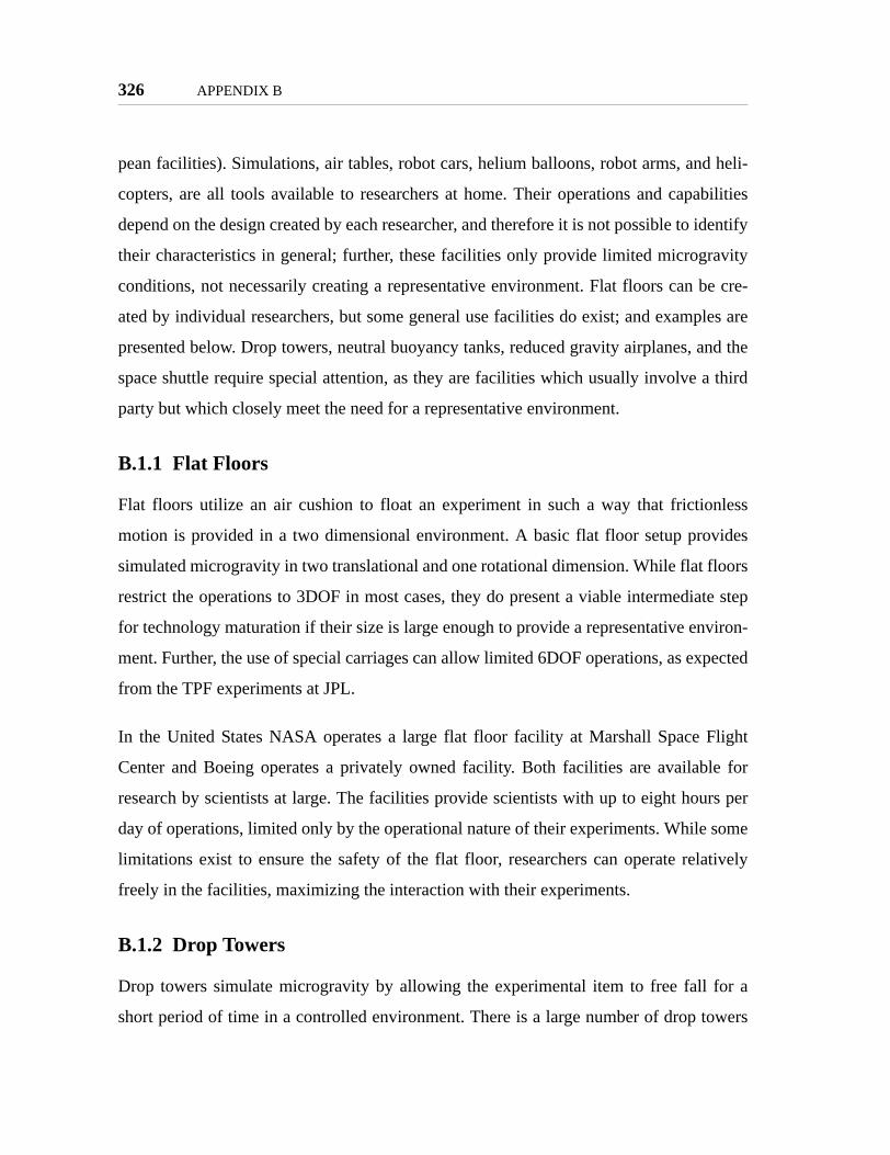
326 APPENDIX B
pean facilities). Simulations, air tables, robot cars, helium balloons, robot arms, and heli-
copters, are all tools available to researchers at home. Their operations and capabilities
depend on the design created by each researcher, and therefore it is not possible to identify
their characteristics in general; further, these facilities only provide limited microgravity
conditions, not necessarily creating a representative environment. Flat floors can be cre-
ated by individual researchers, but some general use facilities do exist; and examples are
presented below. Drop towers, neutral buoyancy tanks, reduced gravity airplanes, and the
space shuttle require special attention, as they are facilities which usually involve a third
party but which closely meet the need for a representative environment.
B.1.1 Flat Floors
Flat floors utilize an air cushion to float an experiment in such a way that frictionless
motion is provided in a two dimensional environment. A basic flat floor setup provides
simulated microgravity in two translational and one rotational dimension. While flat floors
restrict the operations to 3DOF in most cases, they do present a viable intermediate step
for technology maturation if their size is large enough to provide a representative environ-
ment. Further, the use of special carriages can allow limited 6DOF operations, as expected
from the TPF experiments at JPL.
In the United States NASA operates a large flat floor facility at Marshall Space Flight
Center and Boeing operates a privately owned facility. Both facilities are available for
research by scientists at large. The facilities provide scientists with up to eight hours per
day of operations, limited only by the operational nature of their experiments. While some
limitations exist to ensure the safety of the flat floor, researchers can operate relatively
freely in the facilities, maximizing the interaction with their experiments.
B.1.2 Drop Towers
Drop towers simulate microgravity by allowing the experimental item to free fall for a
short period of time in a controlled environment. There is a large number of drop towers

APPENDIX B 327
around the world which range in size from providing only fractions of a second to almost
ten seconds of microgravity time. Important drop towers exist in the United States,
Europe, and Japan. Two of them stand out in our discussion due to their openness for cur-
rent research by a wide number of scientists and their relatively large size: the NASA
Glenn 2.2 Second Drop Tower and the ESA’s ZARM Drop Tower Bremen.
The NASA tower provides 2.2 seconds of microgravity, as its name implies. The drop
takes place off a 100ft tower (the actual drop is 79’1"). A drag shield is used to minimize
air drag. The tower allows up to 12 drops each day, with a clearly defined operational
plan. The center provides a range of support facilities for assembly of the experiment and
integration to the drag shell. The center also provides support hardware such as cameras,
data acquisition equipment, and batteries. After integration the package is lifted to the top
of the tower, at which point the investigator can perform any preparations necessary. The
experiment is provided with electrical control signals which will indicate the exact time of
the drop, such that experiments utilize as much as possible of the drop time and do not
need to waste resources before the micro gravity time. The drop is initiated by cutting the
cables that hold the experiment, achieving microgravity conditions within one-third of a
second. The drop ends when the drag shield falls onto an airbag at the bottom of the tower;
the impact peak values are 15 to 30g.
ZARM has a vertical drop of over 100m, providing 4.74s of free fall; the use of a catapult
to allow a parabolic path of the payload gives up to 10s of free fall. A picture and diagram
of ZARM are shown in Figure B.1 [ZARM, 2000]. But ZARM allows only a maximum of
three drops in one day. Further, the ZARM operations are more complex, requiring the
investigators to be on site at least ten days prior to the tests in order to prepare their pay-
loads. Once the payload is integrated, researchers have remote access to the payload once
it reaches the platform, but before the drop. The small number of drops is due to the fact
that ZARM evacuates its drop tube to under 10Pa (the experiment is pressured), a process
that takes two hours, but remote access to the experiment is available during this time. The
experiment experiences up to 25g at impact. It takes approximately one hour to retrieve

328 APPENDIX B
the experiment. A full set of experiments at ZARM usually consists of 8 to 24 drops,
which takes approximately three to four weeks to complete.
Drop towers present good opportunities for research in terms of the ability of investigators
to work directly with their experiment both before and after the microgravity test. In gen-
eral the size of the experiment is not restricted; the limitations are one to two meters in
diameter and a mass of over 100kg. But:
"...not all types of scientific inquiry are appropriate for the drop tower. Forexample, meaningful microgravity research of the life sciences, biotechnol-ogy, and materials sciences can seldom be conducted in drop facilities (liv-ing things and crystals grow too slowly). On the other hand, flames canspread very quickly, which explains why combustion experiments accountfor approximately 90% of the experiments conducted in the drop tower."[NASA, URL3]
The applicability of drop towers for space technology maturation is limited. Only those
tests that can conclude well within five seconds will benefit from drop towers.
Figure B.1 ZARM drop tower

APPENDIX B 329
B.1.3 Neutral Buoyancy Tanks
Neutral buoyancy tanks are operated in multiple places around the world. The major tanks
are operated by NASA, the Russian Space Agency, and the University of Maryland
(UoM). NASA and the Russian Space agency manage major neutral buoyancy facilities.
The UoM Space Systems Laboratory operates a neutral buoyancy facility for research pur-
poses. All of the tanks are large enough to allow full-sized tests of major spacecraft. For
example, the NASA Neutral buoyancy Laboratory at the Johnson Space Center can hold
several full-sized mock-ups of modules of the International Space Station (Figure B.2
[NASA, URL6]).
NASA manages facilities at JSC and at the Marshal Space Flight Center. The Russian
Space Agency manages a tank at the Gagarin Cosmonauts’ Training Center outside Mos-
cow. The primary purpose of these facilities is to train astronauts for extra-vehicular activ-
ities (EVA). Full scale mock-ups of spacecraft that will require assembly in space are
created; astronauts and cosmonauts use the same tools they will use in space for training.
The only difference usually present is that the astronauts supply of breathable air and
Figure B.2 NASA Neutral Buoyancy Laboratory
330 APPENDIX B
power for the EVA suits is provided by tethers, rather than through the backpacks of EVA
suits.
The UoM SSL tank is the only neutral buoyancy facility dedicated to research. It supports
experiments by undergraduates, graduates, and faculty of the university. The UoM SSL
has also established a program by which external parties can conduct research at the tank.
Research has concentrated on EVA operations and tools, the Ranger vehicle for telerobot-
ics, and the SCAMP project for additional video during EVAs.
Conducting operations in the tanks requires certified SCUBA divers to either perform the
activities and/or support the test subjects. In the case of astronaut training, the astronauts
are supported by large teams of SCUBA divers who monitor their health and progress. In
the case of research, certified divers must perform the experiments. This operational sce-
nario introduces the need for a third party to sometimes perform the experiment, rather
than the scientist always being directly at the controls, since not all research scientists will
have the required certification. This trend will continue from this point forward as the
operational environments get more complex. Given the nature of SCUBA diving, the
facilities usually perform one major session a day. The test session can be several hours
long, allowing a substantial amount of research to be conducted and minimizing the
impact of setup times. The high level of support at the locations, such as SCUBA support,
machine shops, and work areas, allow research to be conducted with low risk. Because
they are based in ground facilities the research is not strictly limited to autonomous opera-
tion, and supplies can be replenished easily. Through the course of a few weeks, a scientist
could get a substantial number of tests performed; the tanks are readily available for con-
tinued research.
The type of activities conducted in neutral buoyancy tanks gives a clear idea of their best
use: human interactions and large spacecraft mock-ups. While neutral buoyancy allows
full 6DOF maneuvers, the effects of drag in water prevent the dynamics from being equiv-
alent to space. Therefore neutral buoyancy tanks are not practical for tests that will be

APPENDIX B 331
affected by drag, such as propulsion tests or precision spacecraft control. Therefore, the
applicability of neutral buoyancy tanks is best suited for that range of research which does
not require precise representation of a microgravity environment, especially with respect
to the dynamics of the system.
B.1.4 Reduced Gravity Airplanes
NASA and the Russian Space Agency operate the most commonly used reduced gravity
airplanes, although other national space programs and private ventures also exist. NASA
operates a program out of its Reduced Gravity Office at the Johnson Space Center. The
Russian aircraft operates out of the Gagarin center outside Moscow. Both programs con-
tinuously support research by government, academic, and private agencies, as demon-
strated by the NASA Reduced Gravity Program Mission Statement:
"To provide a world-class, reduced gravity research platform that empha-sizes user compatibility, quality reduced gravity levels, and a customer-ori-ented support organization."
Reduced gravity is achieved by following a parabolic curve with an amplitude of approxi-
mately 10,000 feet, providing approximately 20 seconds of microgravity. Each micrograv-
ity flight consists of 15 to 40 parabolas, for up to 400 seconds of micro gravity time in a
day (Figure B.3, [NASA, 33899] [NASA, 33898]). This period more than doubles the
available time from drop towers per drop, and is four times that per day; however, it is
substantially less than that of neutral buoyancy tanks. The airplanes provide another
important benefit over the drop towers: the scientists can directly interact with their exper-
iments; it is also an improvement over neutral buoyancy tanks because they do not need
SCUBA certification or equipment, allowing easier interaction with the equipment.
Like with drop towers, operations on a RGA are very structured and time critical. The fol-
lowing example is based on the NASA RGP. Usually experiments operate on the aircraft
one week at a time, with one day for setup and then four days of operations (up to 160
parabolas), requiring scientists to travel to JSC for a minimum of three days and up to a
week. The first day involves integration of the experiment to the aircraft, usually within

332 APPENDIX B
three or four hours. The flight days are especially time critical; the experiments are acces-
sible for about one hour before flight; after takeoff there is a period of about 15 minutes to
start experiments; then parabolas start. The parabolas consist of approximately 40 seconds
of "pull-up", times with 1.8g when the airplane flies towards the top of the parabola, and
then 20 seconds of microgravity as the airplanes flies over the top; 10 parabolas are
repeated consecutively. Five minute breaks are available after parabolas 10 and 30; a 10
minute break is available after parabola 20. While the scientists have full access to their
experiments and can interact with them, this environment is not susceptible to substantial
modifications or repairs without wasting valuable microgravity time. Therefore scientists
must be prepared for successful operation and have backup plans in case of equipment
failure or incorrect assumptions in their setups.
Research conducted at NASA’s RGP covers a wide range of areas including human fac-
tors, medicine, space technology, astronaut training, and combustion. The range of science
is substantially more than that of drop towers or neutral buoyancy tanks for two main rea-
sons: human presence over a substantial period of time. Yet, the RGAs are not suitable for
every type of science either. Like with drop towers, research on biological sciences, some
human factors, and spacecraft control usually requires prolonged exposure to micrograv-
Figure B.3 NASA KC-135 airplane and flight path

APPENDIX B 333
ity. Further, the effects of turbulence and the rotational motion as the airplane goes over
the parabola prevent it from providing completely clean dynamics.
B.2 Space Shuttle"The United States developed the Space Shuttle system to improve itsaccess to space. Since the first flight in April 1981, the Shuttle has carriedmore than 1.5 million pounds of cargo and over 600 major payloads intoorbit. The Shuttle is the first and only reusable space vehicle, and is theworld's safest, most reliable and versatile launch system. It is designed andoperated to support a variety of space-based activities from the delivery oflarge payloads to orbit, the capability of spacecraft retrieval and servicing,to providing a versatile platform to conduct research and developmentexperiments in a "shirt-sleeve" laboratory environment. The Shuttle alsoprovides for experiment return and re-flights.
"Among the Shuttle's greatest strengths, in addition to its amazing array ofcapabilities, is its ability to adapt and evolve to meet new mission require-ments. Whether it means installing a spare part, or sending astronauts on aspacewalk to retrieve an errant satellite, the Shuttle is unrivaled in its abil-ity to adapt real-time to get the job done....:
• Payload Deployment and Retrieval• On-Orbit Assembly• On-Orbit Repair and Servicing• On-Orbit Research• Technology Testbed• Crew Transfer• Cargo Return " [NASA, URL4]
NASA’s Space Shuttle Program (SSP) provides service to a wide range of payloads, from
small experiments operated inside the crew compartment area (middeck) to the deploy-
ment of large satellites into orbit from the payload bay (Figure B.4 [NSTS, XIV]). Among
the most unique features of the SSP is not only the availability of humans, but also the
return of the vehicle, crew, equipment, and products to Earth in a short period of time.
Further, the SSP supports two main operational areas: a payload bay for experiments fully
exposed to the space environment, and the middeck area for experiments that require
human interaction and/or a pressurized environment.

334 APPENDIX B
A typical SSP program starts two years before flight by presenting the necessary docu-
mentation to NASA. During the first year scientists present safety and interface documen-
tation to NASA while they develop their experiments/products. The year before flight
involves the development of the flight hardware and at least six months of integration.
During this time researchers must also train astronauts.[NASA, 2000a]
A typical Space Shuttle mission starts with launch at KSC. After launch the orbiter can
reach altitudes of 100-600nm and inclinations of 28-51deg. Approximately 10 minutes
after liftoff the shuttle performs its final main engine firings to reach the approximate
orbit. Next the payload bays are opened to allow the space radiators to dissipate heat; the
doors remain open for the duration of the mission. The base mission is seven days long,
but a mission can be extended for up to 16 days. The orbiter returns to earth by firing its
main engines to reduce its speed, after which it glides back to earth un-powered.
The standard operating procedure for experiments grows in complexity from previously
presented facilities. While the RGA carry two pilots, three to five operations support per-
sonnel, and 15 to 20 scientists, the space shuttle carries at most seven astronauts that share
research and operational duties throughout the mission. Therefore, conducting experi-
ments begins with the training of astronauts; this training must be substantial enough that
astronauts could conduct the research independently in case there is no real-time link
Figure B.4 Space Shuttle payload bay and middeck

APPENDIX B 335
between the shuttle and ground. Due to limited communications between the shuttle and
ground the experiment must also be ready to operate without further assistance from the
scientist once it gets integrated into the spacecraft, usually no less than four weeks prior to
launch. While software updates are possible once in flight, the process must involve, as a
minimum, the payload integration office and mission control, adding layers of complexity
to the ability to change experiments while in flight. As a result, in general, experiments are
fully designed months prior to being conducted in the shuttle.
Once actual operations start, astronauts follow established procedures for the experiments.
These procedures guide the astronauts through the complete experiment, and usually the
scientist is not involved in real-time. In the cases where a real-time link is available, the
communications is handled through mission control; the scientists communicate with mis-
sion control, who forward the instructions from the scientists to the astronauts. The scien-
tist does directly observe and/or hear what the astronaut is doing, but mission control must
be involved in any communications to the astronauts.
After the experiment is performed the scientists will usually wait for the return of the shut-
tle to ground before accessing their data. Limited communications do exist to allow scien-
tists access to the data prior to return of the shuttle, but the use of these systems will
further add to the complexity of the integration process (a trade-off which scientists must
consider).
Each space shuttle mission carries three types of payloads: primary, secondary, and mid-
deck. The primary payloads are those that justify the flight; each flight can have one or
multiple primary payloads. Secondary payloads, in general, do not define the critical path
of the integration process, but use a significant amount of SSP resources. It is possible for
a number of secondary payloads to together justify a flight as a primary payload. A mid-
deck payload does not define the critical path of the integration process, but still requires
significant SSP resources. [NSTS, XIV]

336 APPENDIX B
In general SSP missions conduct dozens of experiments. The astronaut time must be care-
fully divided throughout the one to two weeks of operations. To accomplish this the SSP
has a clearly defined integration process which dictates how payloads are added to the
program and their priority. Therefore, even though each mission has hundreds of man-
hours available, the operations in the shuttle are even more structured than those in RGAs.
Once a research session is scheduled on the shuttle, scientists must ensure that they will
fully utilize their assigned time. Scientists have to consider the time to set up their experi-
ment, the amount of interaction with astronauts while the experiments run, and the time to
take it apart. Still, each experiment can take on the order of hours (attended), and even
days or weeks (unattended) to complete, rather than a few seconds.
The space shuttle exposes payloads to full microgravity conditions, with almost perfect
dynamics for spacecraft. External payloads are further exposed to space conditions. The
shuttle does orbit the earth in LEO, which means that the orbital dynamics to which exper-
iments are exposed are not necessarily identical to that of final missions (for example,
some experiments may be precursors of earth-trailing satellites). Further, the shuttle does
have orbit correction maneuvers during its mission, at which point experiments are
exposed to non-realistic forces from thrusters. Still, the SSP provides one of the cleanest
microgravity conditions available for research.
The large number of experiments conducted so far in the SSP demonstrates its success in
conducting microgravity research. Projects have covered almost every area of space
research, including astronomy, biological experiments, material science, space technology
development, human factors, and space propulsion; the shuttle has also been used for
deployment and capture of a wide range of spacecraft which have conducted their own
science.
The major challenges in conducting research aboard the space shuttle lie in the integration
process. Because the SSP is a precious facility with limited operations, the integration pro-
cess is not only time-consuming, but also requires substantial investments by the scientists

APPENDIX B 337
in both work hours and money. A decision to use the SSP as a research environment
means the scientists are wiling to compromise between obtaining almost ideal micrograv-
ity conditions in exchange for a substantial jump in operational complexity. The SSP
requires scientists to go through substantial safety approvals and astronaut training. Fur-
ther, it requires that a third party always be involved in operations, since the researcher
cannot communicate directly with the astronauts conducting the experiments.
B.3 The International Space Station"The purpose of the ISS is to provide an “Earth orbiting facility that housesexperiment payloads, distributes resource utilities, and supports permanenthuman habitation for conducting research and science experiments in amicrogravity environment.” (ISSA IDR no. 1, Reference Guide, March 29,1995)
"This overall purpose leads directly into the following specific objectivesof the ISS program:• Develop a world-class orbiting laboratory for conducting high-value sci-
entific research• Provide access to microgravity resources as early as possible in the
assembly sequence• Develop ability to live and work in space for extended periods• Develop effective international cooperation• Provide a testbed for developing 21st Century technology."[NASA, 1998]
The ISS is the only existing facility which provides a true microgravity environment
whose goal is specifically to support scientific research. While its configuration and spe-
cific research goals have changed over time, the basic concept remains the same: to pro-
vide a manned microgravity environment for scientific research and technology
development.
The idea of a permanent space station began in 1984 when President Ronald Reagan
invited Canada, Europe and Japan; Russia joined the program in 1993. ISS development
has been split into three phases. ISS Phase I took place before assembly and consisted of a
series of cooperative research flights between the United States and the ISS partners. Most

338 APPENDIX B
notably, this involved a series of rendezvous flights between the Space Shuttle and the
Russian space station MIR, cosmonaut flights on the Space Shuttle, and U.S. astronaut
stays on MIR; research on MIR was expanded to US and other international partners. In
ISS Phase II, the knowledge gained from Phase I operations is being applied to the on-
orbit assembly of the ISS. ISS Phase II will conclude with the successful assembly of the
U.S. and Russian components of the ISS that are necessary to begin Station research. ISS
Phase III development consists of the final research outfitting of the ISS, as the European,
Japanese, and Canadian elements are transported to orbit and the Station becomes fully
operational. [IMBOSS, URL]
Assembly of the ISS began in 1998 and will reach "US Core Complete" after mission 10A
(predicted for the end of 2006), marking the end of Phase II. Figure B.5 ([NASA, ULR8])
shows a picture of the ISS on October 2002. At that point the ISS habitable modules will
consist of the Zarya control module, two nodes, three docking modules, the US Destiny
Laboratory, the ESA Columbus laboratory, the Japanese Experiment Module (including
an exposed facility), a centrifuge module, and two airlocks. The exposed elements will
include solar arrays to provide up to 30kW of power for research, multiple express pallet
mounting points, a science power platform, and the CSA robotic arm. At core complete,
the ISS will be permanently inhabited by three people.
Like the space shuttle, the ISS offers extremely clean microgravity conditions in both its
pressurized and exposed modules. The only limits of the ISS lie in the need for orbit cor-
rection maneuvers, which introduce artificial forces on the experiments, and the orbit
location in LEO. As compared to the space shuttle, though, the ISS long-term deployment
allows experiments to be exposed to microgravity conditions even for years at a time. The
constant number of servicing flights to the ISS allow experiments to be returned to earth
within a reasonable time. The expanded number of flights, beyond the space shuttle, allow
the hardware of experiments to be upgraded in shorter time periods than possible with
SSP.

APPENDIX B 339
As with the space shuttle, ISS operations are highly structured, time-critical, and require
the presence of third parties throughout a substantial part of the program. Even with three
humans permanently present in the ISS, their time is extremely precious. NASA and its
partners spend incredible amounts of time organizing the schedules of astronauts. Even
when an astronaut completes their duties early, a number of activities are always ready to
be performed. Therefore, many scientific experiments are likely to be performed at ran-
dom times, preventing the scientists to interact in real-time with the astronauts. As such,
like before, all experiments must go through enough training and integration that they can
be conducted independently by the astronauts. As with the SSP, when real-time communi-
cations are possible, the scientist must interface with mission control and the payload inte-
gration office, rather than directly with the astronaut. The ISS does provide a substantial
improvement on communications, such that when properly planned, real-time audio,
video, and data transfer (both downlink and uplink) are possible. Even though the opera-
tions of the ISS are clearly more complex than a scientist conducting research in their own
facility, the trade-off between operational complexity and availability of microgravity is
Figure B.5 The ISS on October 2002

340 APPENDIX B
not as important because of the availability of substantial astronaut time, real-time interac-
tion, and ability to upgrade both hardware and software in a reasonable amount of time.
B.4 Past Space-based Laboratories
The ISS had both US and Russian predecessors: the US Skylab, Space Lab, and the Rus-
sian Sályut and MIR Space Stations. This section presents a quick historical review of
these four different facilities, as well as their contributions to scientific research in space
and the development of the ISS.
B.4.1 Sályut
Multiple Sályut space stations were built through the 1970’s and into the 1980’s. The first
station was launched in May 1971. Its first crew worked on the station for 21 days; unfor-
tunately the crew died after a de-pressurization accident upon reentry. The second mission
was destroyed in an explosion of the launch vehicle. The third attempt reached orbit in
1973, but contact was lost before a crew could reach the station. The fourth version flew
successfully in 1974. The sixth and seventh missions flew in 1977 and 1982, respectively.
The sixth mission was the most successful, recording 27,785 orbits of Earth and five
manned expeditions over four years and ten months of operations. The longest crew dura-
tion was 185 days. The seventh mission was aloft for four years and two months; two to
six crew members were aboard at any one time through six main expeditions and four sec-
ondary flights (including French and Italian cosmonauts). Mission durations of up to 237
days were achieved. The seventh and last Sályut mission ended in June 1986; the space-
craft burned up in the Earth’s atmosphere in 1991.
The Sályut program featured important capabilities seen in the ISS. The stations per-
formed docking of both manned and unmanned spacecraft for crew rotation and resupply
missions. For this purpose, the stations had two separate docking ports. The stations had
an airlock, which allowed dozens of EVA’s to take place. Of special importance to the ISS
program is that a number of international cosmonauts flew to the Sályut stations over the

APPENDIX B 341
years, the first time that international cooperation would occur in a space station. Lastly,
the objective of the Sályut program was directly in line with that of the ISS:
"Objectives: Continuation of scientific research on board manned spacecomplexes in the interests of science and the Soviet national economy; test-ing of advanced systems and apparatus for orbital stations. Continuation ofthe scientific research in progress on board manned space complexes in theinterests of science and the national economy; testing of advanced systemsand apparatus for orbital stations." [Astronautix]
The sixth mission completed many of its objectives with a wide range of scientific equip-
ment: multi spectral camera system, high resolution topographical camera system, 10 m
diameter radio telescope, alloying/materials processing furnace, containerless processor
for semiconductor materials, 1.5 m diameter cryogenic submillimeter/ultraviolet/infrared
telescope, Refraktion and Zarya spectrometers for sun/moon views through Earth's limb,
experiment for coating of plates with materials, gamma ray telescope, plant growth unit,
and cardiovascular monitoring system. The seventh mission was dominated by military
research after cutbacks in other military programs forced the use of the Sályut for this pur-
pose.
B.4.2 US Skylab [Belew, 1977]
Skylab was the United States’ first space station. It was more than the actual space station,
it was a comprehensive scientific program. The program consisted of four launches: one
unmanned delivery of the space station and three separate manned missions. The station
was launched in May 1973 and remained in operation through its third man mission which
ended in February 1974. Through these months in space Skylab completed more than 100
experiments in a wide range of topics.
The Skylab station consisted of five major elements (Figure B.6, [Belew, 1977]): com-
mand and service module (CSM), orbital workshop, airlock module, docking adapter, and
the Apollo Telescope Mount for solar observations. The unmanned launch put into orbit
all the modules except the command and service module; the CSM, a standard Apollo
command module, carried the crew to the station and returned them to Earth at the end of

342 APPENDIX B
their mission. The majority of the activities occurred in the orbital workshop, which
included the living and working quarters.
The Skylab science covered multiple disciplines. The Apollo Telescope provided unprec-
edented observations of the sun. The location of Skylab outside the atmosphere also
allowed studies of stellar astronomy, including the study of comet Kohoutek. Man’s
adaptability to long-duration space-flights was studied; this included both physiological
and behavioral research. Observation of the Earth provided more than 40,000 pictures for
scientists to study agriculture and forestry, geological applications, the oceans, coastal
zones, water resources, atmospheric phenomena, regional planing and development, and
remote sensing technologies. Substantial research was also conducted in the area of mate-
rials science, including crystal formation, homogeneity in semiconductors, diffusion in
liquid metals, and solidification of metals. Lastly, Skylab also served as an educational
environment; a large number of student projects were completed by the astronauts.
As a predecessor to the ISS, Skylab started the goal to develop space facilities dedicated to
scientific research. While the scientific goals of Skylab were strictly defined to understand
Figure B.6 US Skylab

APPENDIX B 343
the human physiological responses to long-term microgravity conditions, with a pre-
defined set of additional experiments, the major goals were always to support science.
B.4.3 Space Lab [Emond, 2000]
While not a true space station, the Spacelab program helped pave the way for the ISS in
many ways. Spacelab was not a spacecraft launched to space for long-term microgravity
research; rather, the Spacelab program was a successful attempt to open the use of the
space shuttle to a broad range of research by the international community. Through a sys-
tem of modules, Spacelab provided both pressurized and un-pressurized platforms. NASA
operated the program, including providing the space shuttle to carry the modules. The
ESA designed the modules and supported the operations of the laboratory’s payloads.
The program lasted 17 years, from 1981 to 1998. Spacelab modules flew on 36 space shut-
tle missions; 16 missions were with pressurized modules, the rest with exposed pallets. A
total of 375 days of flight were logged. Throughout its time it supported over 800 distinct
experiments, leading to thousands of research articles and hundreds of graduate theses.
Four principle components formed the core hardware of the Spacelab program. The
Spacelab Module provided a pressurized environment. The Spacelab Pallet allowed large
instruments to be in direct exposure to the space environment and broad fields of view.
The Instrument Pointing System provided a high-accuracy mount for space telescopes.
The Mission-Specific Experiment Support Structure supported up to 3000 pounds of pay-
load.
Spacelab was a milestone towards the ISS in two important respects. It began unprece-
dented international space collaboration. Due to the size of the program, researchers, engi-
neers, scientists, and peacemakers had to learn how to properly use the facilities that
Spacelab provided. As a special part of the Spacelab program, the Spacelab 1 mission
docked a Spacelab Module to the Russian MIR space station, providing a true laboratory
environment for MIR, and creating, albeit for a short time, the first truly international
space station for research.

344 APPENDIX B
By developing complex systems, which were different with each mission, many lessons
were learned on how to use the facilities; sometimes what was learned was that you have
to fly it to learn how to use it. Spacelab provided experience on integrating a wide range of
experiments from multiple disciplines and countries. It also provided an environment
where the scientist was directly involved in the actual process of conducting the science;
scientists knew when execution would take place and had input on what would happen.
Spacelab provided a clear perspective on what to expect from the operations of the ISS.
Spacelab fostered a broad range of research activities spanning widely separate fields of
study. While research on the Sályut and Skylab missions was pre-defined and strictly
scheduled, Spacelab opened the doors for a much broader range of science to be con-
ducted. No longer was the science for the full program pre-defined, but rather unsolicited
research could be conducted. Spacelab provided both the hardware and operational sup-
port needed to broaden the research spectrum. The program welcomed experiments
exposed to space and pressurized in the module. The timeline allowed development of
new experiments over time. New technologies that appeared after the program was
launched could be integrated to enable new science.
Spacelab created a cultural change in the ways to perform microgravity research. The
space stations by both the US and Russia demonstrated the ability of humans to reside in
space for long periods of time. Spacelab demonstrated the ability to create an international
program which welcomed a wide range of science.
B.4.4 MIR
MIR was constructed from 1986 to 1996. The MIR Core Module was launched in 1986
and provided living accommodations and station control. Two scientific modules, Kvant I
and II, were launched in 1987 and 1989, respectively. A third module, Kristall, was added
in 1990. The Spektr module, added in 1995, added space for a US astronaut to live in
MIR. In 1996 the Docking module was added to provide a connection port to the US space
shuttle. Figure B.7 ([NASA, URL5]) shows a picture of MIR taken from the Space Shut-

APPENDIX B 345
tle. MIR was burned in the Earth’s atmosphere in March 2001. Through its lifetime, MIR
was serviced by Soyus (manned) and Progress (supplies) vehicles.
As a whole the MIR program surpassed all of its expectations. Originally scheduled for
five years of operations, it was operational for almost 15 years. Even after the original
Russian plans were complete, the station continued to grow to welcome US astronauts and
the space shuttle. By the end of its life, when docked with the Space Shuttle, the joined
MIR station and space shuttle formed history’s largest spacecraft.
But MIR was not without problems. Through its history MIR had to be serviced conti-
nously. Assembly of the station required several unexpected EVAs after failed automatic
dockings. The station suffered from fires, broken computers, oxygen emergencies, and a
collision with a Progress vehicle in 1997. Unfortunately for the research community these
problems meant that a high percentage of cosmonaut time was spent in maintaining MIR.
The time spent on research in MIR was greatly affected by its history of problems. Yet, all
of these experiences have served as lessons for the ISS.
Research on MIR was conducted in a broad number of areas. During the Shuttle-MIR pro-
gram time, research took place on: advanced technologies, earth sciences, fundamental
biology, human life sciences, ISS risk mitigation, life support risk mitigation, micrograv-
Figure B.7 The MIR Space Station

346 APPENDIX B
ity, and space sciences. Advanced technologies included materials science and the charac-
terization of the micro-accelerations in MIR, which would help in the development of
science facilities in the ISS. Combustion experiments also took place. Earth sciences con-
centrated on remote sensing and space photography to make detailed assessments of the
Earth. Both the biosphere and the atmosphere were studied. Biology research concentrated
on studying the effects of microgravity on the development of plants and animals;
research on radiation effects was also performed. Extensive human life sciences studies
took place, among the main research areas were: the cardiovascular system, endocrinol-
ogy, hematology, human factors, immunology, microbiology, muscle and bone, neuro-
science, pharmacology, and radiation studies. Space science experiments collected cosmic
dust over extended periods for analysis on Earth.
MIR played a critical role in the development of the ISS. Phase I of the ISS involved the
interactions of NASA and the RSA in using MIR and the Space Shuttle as a test bed for
the future development of the ISS. Multiple shuttle flights took place to demonstrate
assembly of the ISS by assembling new parts to MIR. EVAs which utilized both the Rus-
sian and the US hardware took place. The living environment of MIR was fully analyzed
to develop standards for the new station, including air quality, noise levels, and water
quality. The effects of crew motions on the structure were measured to help the design of
ISS experiment support systems. The external environment of MIR provided valuable
information on the external design of the ISS.
Quite possibly the most important benefit from Phase I was to force the internal partners,
including the astronauts and cosmonauts, to work in a long-term relationship in a perma-
nently manned space station. While Sályut had international astronauts visit the stations
and Spacelab established a long-term relationship between international partners, neither
required two separate organizations to work together to support life in space for a long
period of time. The ISS Phase I program, using MIR, forced NASA and RSA to solve crit-
ical problems together; that required understanding each other.

APPENDIX B 347
Phase I drove significant designs of the ISS, including improvements to the rendezvous
and docking instruments, "quick-disconnect" cables that come apart in seconds in the case
of emergencies, and prevention of moisture buildup. It also provided important lessons for
the administration of the ISS. NASA would work on more flexible schedules for astro-
nauts. NASA surgeons learned how to perform medicine on a space station. And, perhaps
the most important lesson learned from Phase I was humility; learning that, as with
Spacelab, there is a lot to learn after launch. NASA learned how different operating a
space station is from the shuttle. [Burrough, 1998]

348 APPENDIX B

Appendix C
OTHER REMOTE RESEARCH FACILITIES
This appendix studies remote research facilities currently under operation. Specifically,
research in the Antarctica and sub-sea/ocean exploration facilities are reviewed. In both of
these cases it is common for the investigations to occur by a limited set of scientists; the
full research team is not always present where the research is being conducted. Further,
the operators in charge of the facilities are not always the researchers. While sometimes
the full research team can be present for Antarctic/Ocean research missions, these facili-
ties present the best models for remote operations of shared facilities.
C.1 Antarctic Research
While human exploration of the Antarctic region dates as far back as the travels of Magel-
lan in 1520, there are two important periods in Antarctic scientific history highly relevant
to the ideas of cooperative research and the establishment of remote scientific bases: the
years around the 1957-58 International Geographical Year (IGY) and today. The years
around IGY are of special importance since they resulted in the creation of the Antarctic
Treaty System and the Special Committee for Antarctic Research (SCAR). Before the
treaty and SCAR, Antarctica exploration, while significant, had no overall plan, and was
mostly driven by commercial interests. A realistic potential of conflict existed by several
nations making claim to the land, while other nations simply went through it without mak-
ing claims, but expecting to be able to cross again. The Antarctic Treaty is a political
349

350 APPENDIX C
agreement created between 12 nations to guarantee the non-military use of the Antarctic
continent; over 30 nations now adhere to the treaty (Figure C.1 - from [BAS2] [BAS1] -
shows a map of current stations and a picture of research being conducted in a British sta-
tion). SCAR is a scientific tool for research in the region; it works in parallel and as an
advisor to its political counterparts in the Antarctic Treaty to promote science and guide
the politics of the region.
When discussing the Antarctic Treaty System as a mechanism for scientific research, Wil-
liam F. Budd starts with the following thesis:
"The main thesis of this chapter is that humankind’s quest for knowledgeneeds to be recognized as the primary motivation for the high level of con-tinued interest and activity in the Antarctic. The treaty nations, through theAntarctic Treaty System, have supported this objective." [NRC PRB]
Like the ISS today, the Antarctic Treaty System and SCAR were formed with science as
their primary goal. At a Conference in honor of the 30th Anniversary of the Antarctic
Treaty System six primary motives were identified:
1. Basic Research
2. Political - national presence and prestige
Figure C.1 Antarctic research stations

APPENDIX C 351
3. Economic - natural resources and technology development
4. Military - although against the treaty, recognized as an important militaryarena
5. Jurisdictional
6. Environmental
All of these motives continue to spur developments and research programs in the Antarc-
tic Region. At the same conference, though, "Finn Sollie [who] was intimately involved in
the drafting of the Antarctic Treaty... [expressed that] His major point was that science in
fact was the crucial element that made the treaty possible. Without science there wouldn’t
have been an Antarctic Treaty." [Elzinga, 1993]
The requirements of science ultimately set the guiding principles of the Antarctic Treaty
System:
• free access to Antarctic territory
• free use
• free exchange of information
• allowance of inspections of any base by any member country’s scientist
• joint planning and execution of activities
• peaceful uses only
• no territorial claims
"Antarctic politics is unique, and truly in a world of its own. While on a national level
local issues may determine how a country runs its Antarctic programme and funds its sci-
ence, on an international level Antarctic politics and science are about co-operation."
[Burton, 2004] Nations fund Antarctic science either individually or in collaboration,
therefore funding processes differ greatly from nation to nation. But the lack of national
boundaries allows collaborations to occur easily. It is not uncommon for scientists to work
in bases of countries other than their own; as long as the science is in-line with the stan-
dards of the host country (and its scientists agree), bases welcome investigators from
across the world.

352 APPENDIX C
While the scientific community has achieved an environment which reduces the politics in
the Antarctic substantially, they still must endure the physical conditions of the southern
continent. To this purpose each country that has a base has established vast logistical sup-
port for scientific research. In the case of the United States, for example, there are three
different bases (McMurdo Station at 77°53’S, Amundsen-Scott South Pole Station at
90°S, and Palmer Station at 64°46’S). Temporary camps can be setup during the summer
months out from McMurdo Station. Automated unmanned data collection can be estab-
lished; the University of Wisconsin has placed automatic weather stations and supports ice
coring and drilling. Several research ships are available (the Laurence M Gould and the
Nathaniel B. Palmer are the primary ones). Several support instruments are also available,
such as differential GPS and radars. A vast database of maps, aerial photographs, and bib-
liographic documents exist to help prepare research missions.
In these large organizations there are multiple challenges. "Logistics has a hardware side
and a software side. The latter is the more important, covering the know-how and compe-
tence of the people operating vessels, the ship and crew that are there to support the scien-
tists, the helicopter pilots, technicians, consultants, etc. It was pointed out that a ship
should always be under the command of the captain, and not of the scientist." [Elzinga,
1993] Scientists conducting research in Antarctica must face social and cultural factors,
understanding that issues such as safety may override the scientific needs. The same holds
true for the ISS, where even though the astronaut conducts the science and manages the
spacecraft, they must balance their priorities, and science may not always be the highest.
The conclusion in Antarctic research is that the ship’s captain must always be in charge; in
the ISS there is always going to be someone in charge over the scientist.
It is also of use to understand the challenges posed by the Antarctic environment, as some
of these closely resemble some of the features that define the uniqueness of the ISS. When
developing an experiment for operations in the Antarctica, the following factors will play
an important role in the design [Ashley, 2004]:
• Transporting large structures is a cumbersome and slow process

APPENDIX C 353
• High altitude environment reduces the effects of convection and fans
• Large temperature fluctuations throughout the day and night cause multipleproblems
- Need to insulate for temperatures as low as -80°C
- Must account for changes of up to 30°C
- Batteries loose capacity
- O-ring become brittle
- Thermal compression and expansion of materials
- Metals become brittle
• High relative humidity approaching 100%
• Electrostatic damage at room temperature (humidity quickly drops)
• Difficult to maintain exposed equipment
An example of a manner to overcome the difficulties of Antarctic research comes from the
development of a robotic autonomous telescope for use in the Antarctica by the University
of New South Wales, Australia. The approach has been to minimize the number of com-
puters, addressing many of the issues. Both hardware and software watchdogs watch over
the computers. A priority of the computer systems is to prevent reaching ambient temper-
ature (as low as -80°C). They have taken a modular approach to the software environment,
allowing scientists to create their own programs for telescope control. Still, even for the
design of an autonomous telescope, they conclude that "for the foreseeable future humans
will be an essential component in building, operating and maintaining telescopes in Ant-
arctica." [Ashley, 2004]
"Without pre-existing infrastructure and support capability, conductingfrontier science is impossible... for the explorer, engaged in comprehend-ing their surroundings this [be an adventurer] is no longer possible. Nationsconducting Antarctic science go to great lengths to provide facilities thatare safe and practical for their inhabitants. For every scientist present, fouror five people are there to support them... Nations that don’t put this effortinto their stations... are not in Antarctica to do science." [Burton, 2004]
Researchers in Antarctica do have the opportunity to be present where they plan to con-
duct research, although the conditions are not ideal. During the summer months the bases

354 APPENDIX C
are overcrowded; the winter months have very limited daylight. Schedules are an impor-
tant part of the scientists routines. To start, every instrument must be tested at home before
deployment to Antarctica. The base stations do have supplies to repair equipment,
although it may take time to schedule the available support personnel or the facilities
needed to conduct the repairs. Antarctic researchers have the benefit that obtaining parts
from their home laboratories is only a week away during the summer months. The sched-
ule plays an important part for many scientists that must leave before winter, since it is
essential to finish their research before then.
For those that reside in the bases during the winter, they will face inter-personal chal-
lenges, where it is impossible to avoid those living in the base. Communications have
highly improved the conditions of conducting research in the Antarctic. All staff in the
base can communicate with the rest of the world and be informed. When scientific teams
get split those residing in the base can contact the rest of the team via video conference.
Through extended communications research occurs at Antarctica year-round.
Antarctic research that does not require the scientist to conduct fieldwork also occurs.
Locations such as the Antarctic Research Facility (ARF) in Florida State University have
been setup to provide access to Antarctic research. The ARF services include vast litera-
ture through journals and books, photography and map collections. The facility also pro-
vides access to specialized equipment such as x-ray sensors, diffractors, and imagers,
digital and analog photography, and sediment processing facilities. The ARF collects sam-
ples from the Antarctica through the US vessels and makes them available to scientists;
the ARF even supports special requests for samples.
Even if some facilities exist to permit off-site research, the vast investment in supporting
fieldwork in the Antarctica clearly points to the fact that the presence of humans in the
research environment remains critical. Every nation that has a scientific presence in the
Antarctica provides a large number of support personnel and equipment. In many cases
thousands of support staff help hundreds of scientists.

APPENDIX C 355
There are several lessons to be learned from Antarctic research. Possibly the most impor-
tant lesson lies in the development of the Antarctic Treaty, where science played the driv-
ing force, rather than politics. The vast success in cooperation between nations that
conduct science in the Antarctic is overwhelming. There are also lessons regarding remote
operations. The practices to develop experiments which operate in a harsh environment,
where simple repairs and operations are not possible, provide valuable lessons for the
design of ISS experiments. Technological improvements in communications have helped
both the operations and science in the Antarctic. But, at the same time, the environments
have been set up to ensure that at least a portion of the scientists involved in the research
are present. Therefore, Antarctic Research history says that when possible it is best to
have the researcher conduct the experiments. This means that the ISS must provide
enhanced capabilities such that astronauts conducting research remotely can communicate
effectively with the scientists on Earth.
C.2 Ocean Research and Exploration
The challenges incurred in ocean research closely resemble those of space research. The
design and operation of ocean facilities must allow for humans to conduct research in a
harsh environment: life support is essential; the presence of humans is limited; mechanical
tools must enhance the human ability to manipulate the environment; in many cases the
facility operates separate from its home station - it must ensure safe return to its base;
communications play an essential role in the ability to conduct science; and the vessel
must support all of these functions on its own power.
Ocean engineering manned vehicle systems can be grouped into four primary areas, just
like microgravity facilities. These areas are [Penzias, 1973]:
• Conventional diving systems - these range from sponge divers and SCUBAgear to hard-hat body suits which allow humans to explore in shallowdepths. Humans are usually exposed to the environment, and as such thehuman performs most of the actuation directly. The gear’s primary task is forlife support.
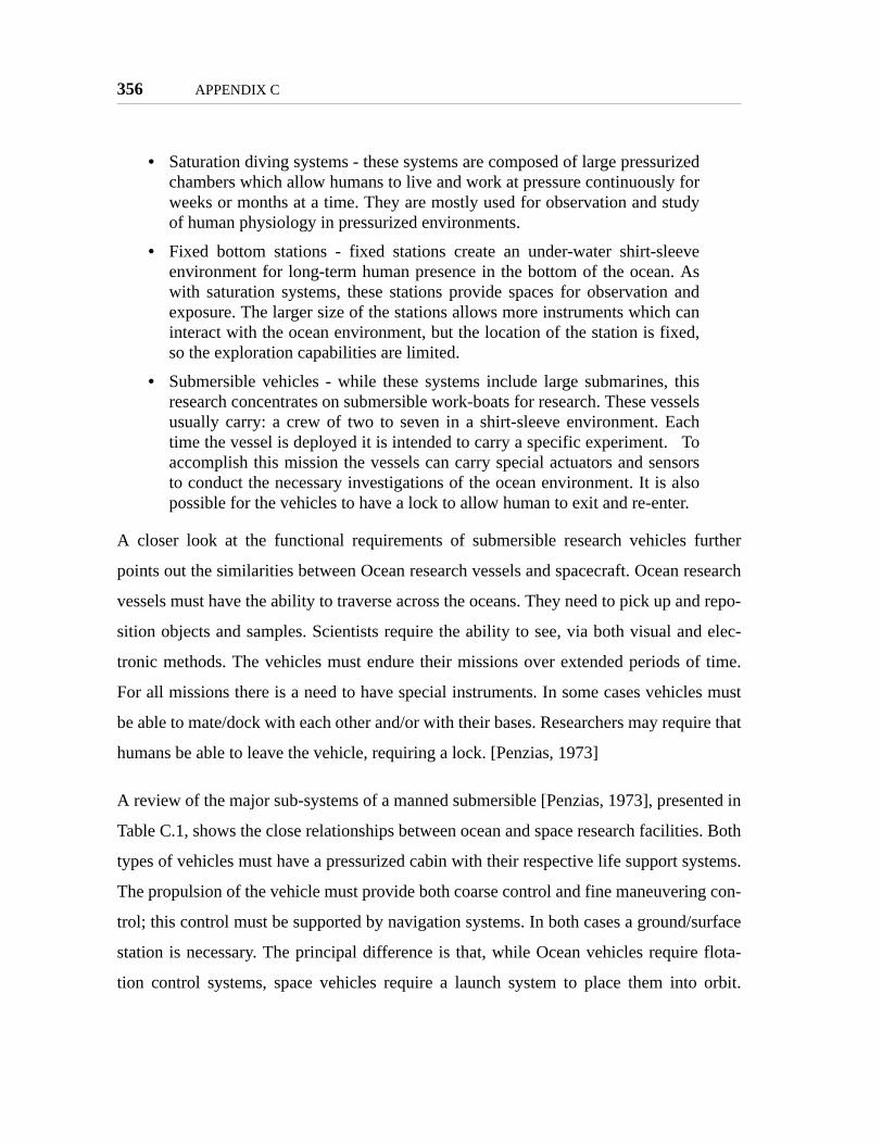
356 APPENDIX C
• Saturation diving systems - these systems are composed of large pressurizedchambers which allow humans to live and work at pressure continuously forweeks or months at a time. They are mostly used for observation and studyof human physiology in pressurized environments.
• Fixed bottom stations - fixed stations create an under-water shirt-sleeveenvironment for long-term human presence in the bottom of the ocean. Aswith saturation systems, these stations provide spaces for observation andexposure. The larger size of the stations allows more instruments which caninteract with the ocean environment, but the location of the station is fixed,so the exploration capabilities are limited.
• Submersible vehicles - while these systems include large submarines, thisresearch concentrates on submersible work-boats for research. These vesselsusually carry: a crew of two to seven in a shirt-sleeve environment. Eachtime the vessel is deployed it is intended to carry a specific experiment. Toaccomplish this mission the vessels can carry special actuators and sensorsto conduct the necessary investigations of the ocean environment. It is alsopossible for the vehicles to have a lock to allow human to exit and re-enter.
A closer look at the functional requirements of submersible research vehicles further
points out the similarities between Ocean research vessels and spacecraft. Ocean research
vessels must have the ability to traverse across the oceans. They need to pick up and repo-
sition objects and samples. Scientists require the ability to see, via both visual and elec-
tronic methods. The vehicles must endure their missions over extended periods of time.
For all missions there is a need to have special instruments. In some cases vehicles must
be able to mate/dock with each other and/or with their bases. Researchers may require that
humans be able to leave the vehicle, requiring a lock. [Penzias, 1973]
A review of the major sub-systems of a manned submersible [Penzias, 1973], presented in
Table C.1, shows the close relationships between ocean and space research facilities. Both
types of vehicles must have a pressurized cabin with their respective life support systems.
The propulsion of the vehicle must provide both coarse control and fine maneuvering con-
trol; this control must be supported by navigation systems. In both cases a ground/surface
station is necessary. The principal difference is that, while Ocean vehicles require flota-
tion control systems, space vehicles require a launch system to place them into orbit.

APPENDIX C 357
Overall, though, the similarities between the two predict that the challenges are answered
in similar ways.
[Cunninghman, 1970] studied the design of an ocean engineering vessel in the 1970’s.
The study included a survey of researchers to identify the most important tasks that
needed to be performed in such a vessel. This survey identified the functional require-
ments of the vessel. There were some interesting results relevant to the design of micro-
gravity laboratories:
• Four features were considered luxuries, that is, they are not high priority forimplementation; of these features one is relevant to microgravity laborato-ries: real-time data analysis. The survey concluded that many scientists pre-ferred to collect the highest amount of data possible for post-analysis, ratherthan invest in real-time data analysis.
• Large laboratory areas were of low priority. Instead, the scientists preferredto have large deck areas. Deck areas are large common spaces for thedeployment of experiments. Rather than limit the capabilities of their equip-ment due to size limitations, scientists preferred to have smaller analysisareas in the vessel, and perform more in depth analysis off the vessel. This isnot to say that laboratory areas were not needed. Five specific laboratoryareas (structures and materials, instrumentation, chemical and biological,
TABLE C.1 Major sub-systems of space and ocean research vehicles
Ocean Vehicle Space VehiclePressure Hull or Cabin Pressurized Cabin
Structure(beyond pressure hull)
Truss elements
Flotation Launch VehiclePower Power
Propulsion PropulsionManeuvering ManeuveringLife Support Life SupportNavigation NavigationWork Space Research Space
Surface Support Ground Station

358 APPENDIX C
electrical and electronic, and human engineering) and two general purposelaboratory areas (machine shop and computer center) were identified.
• It appeared from the analysis that scientists would like to conduct more thanone experiment at a time; the results called for multiple hoists to deployexperiments.
Current ocean research vehicles at the Woods-Hole Oceanographic Institute [WHOI,
URL] show that the results of the early survey still apply in general. New technology
allows integration of more tools for data analysis (both for real-time and post-processing)
into new vessels, but the primary goal of the vessels remains to provide human support
and the deployment of equipment for exploration and research. The most important func-
tions of these vessels are to:
• support missions of days to months
• provide navigation and communication systems
• support for multiple projects
- availability of multiple winches for experiment deployment
• carry submersibles
- provide space for scientists: manned submersibles require only one pilotand have space for one or two scientists.
- allow unmanned observation and sample recovery
Figure C.2 WHOI research vessels Knorr (left) and Alvin
APPENDIX C 359
The design of submersible research vessels closely matches the design needed for a space-
based research laboratory, such as the ISS. The challenges and results of the design of sea
vessels can be applied to some aspects of the designs for microgravity facilities. Yet, the
review of both past and current ocean engineering systems shows a trend similar to that of
Antarctic research: take the scientists to the place of research.

360 APPENDIX C

Appendix D
THE INTERNATIONAL SPACE STATION
This appendix presents an review of the International Space Station Program and the facil-
ities that are or will be available for research. First, the appendix reviews the objectives of
the ISS and the identified research directions for the station. Next, it presents an overview
of all the ISS components. That is followed by a more in depth review of the components
which directly support research aboard the ISS. The appendix ends with a presentation of
the identified challenges of the ISS and expected upgrades to the program to overcome
these challenges. Chapter 2 utilizes this review to identify the most important resources
provided by the ISS.
D.1 Objectives and Research Directions
The objectives of the ISS as stated in the ISS Familiarization Manual developed by NASA
are:
"The purpose of the ISS is to provide an “Earth orbiting facility that housesexperiment payloads, distributes resource utilities, and supports permanenthuman habitation for conducting research and science experiments in amicrogravity environment.” (ISSA IDR no. 1, Reference Guide, March 29,1995)
"This overall purpose leads directly into the following specific objectivesof the ISS program:• Develop a world-class orbiting laboratory for conducting high-value sci-
entific research
361
362 APPENDIX D
• Provide access to microgravity resources as early as possible in theassembly sequence
• Develop ability to live and work in space for extended periods• Develop effective international cooperation• Provide a testbed for developing 21st Century technology." [NASA, 1998]
After creating these objectives, NASA worked to further detail the research objectives of
the ISS. To this purpose, NASA has created an ongoing program to determine the
"research directions" of the ISS. During the development of these directions, NASA first
defined the ISS as a special type of laboratory, one which has three special purposes:
• "an advanced testbed for technology and human exploration;
• a world-class research facility; and
• a commercial platform for space research and development." [NASA, 2000]
As of January 2000 the NASA Office of Life and Microgravity Science Applications had
identified a number of research fields which can directly use the resources provided by the
ISS to advanced human knowledge and provide benefits to the people in the ground. The
identified fields include (adapted from [NASA, 2000]):
• Biomedical research and countermeasures / Advanced human supporttechnology - what knowledge and technology are necessary for humans tolive and function productively beyond the Earth’s surface.
• Biotechnology - produces and characterizes biological molecules andassemblies important to basic and clinical research.
• Combustion science - the basic mechanisms of combustion can be moreeasily studied in microgravity, where scientists can make observations andmeasurements of combustion and the systems and processes it enables.
• Fluid physics - the universal nature of fluid phenomena, which affect every-thing from transport dynamics in the human body to the mixing characteris-tics of the atmosphere, makes this research fundamental to all areas ofscience and engineering.
• Fundamental physics - microgravity enables the development of uniformsamples, the free suspension of objects, and the lack of mechanical distur-bance on experimental subjects to test the fundamental physical laws.

APPENDIX D 363
• Gravitational biology and ecology - studies in gravitational biology andecology seek to advance our understanding of how the ubiquitous force ofgravity affects the many stages of plant and animal life.
• Materials science - the ISS gives researchers to study the relationshipsbetween the structure, properties, and processing of materials without buoy-ancy-induced convection, sedimentation, or hydrostatic pressure. Micro-gravity also provides the chance to investigate “containerless processing”.
• Space science - from its orbital position, the ISS affords researchers a long-term “window on the universe” from which to study the structure and evolu-tion of the cosmos.
• Engineering research and technology development - advances in engi-neering research and technology development (ERTD) can help reduce costsand improve the performance of future government and commercial activityin space, and enhance the quality of life on Earth. ISS research helps validatethe technologies for long-duration space exploration, power generation andstorage, robotic manipulation capabilities, automatic maintenance, andspacecraft control. New applications, processes, and technologies promise tobenefit the telecommunications, water and power, construction, and otherindustries on Earth.
• Space product development - commercial researchers will springboard offof basic science and engineering to use the knowledge gained from the ISSresearch to create new products and processes to benefit the medical andpharmaceutical fields, the electronics and chemical industries, and the engi-neering community, among others.
• Earth science - the orbit of the ISS will cover about 85% of our planet’s sur-face, making it a useful platform for ongoing Earth science research to assessthe global trends such as: atmospheric and climate change; weather patterns;vegetation and land use patterns; and food, water, and mineral resource use.
D.2 Components of the ISS
Figure D.1 shows the expected configuration of the ISS at US Core Complete, as of July
23, 2004. Once this configuration is achieved, the ISS will be composed of the following
major modules (the following descriptions were adapted from [NASA, 1998] to reflect US
Core Complete):
• Node - The Node is a U.S. element that provides six docking ports (fourradial and two axial) for the attachment of other modules. It also provides

364 APPENDIX D
Figure D.1 The ISS at US Core Complete
ISS
Tech
nic
al C
on
fig
ura
tio
nE
nd
ors
ed
by I
SS
Head
s o
f A
gen
cy o
n J
uly
23, 2004
Mul
tipur
pose
Lab
orat
ory
Mod
ule
(MLM
) *
Rese
arch
Mod
ule
(RM
)*
•RM
and M
LM
are
in
clu
ded in
Russia
n p
lans a
nd launched o
n R
ussia
nveh
icle
s
CAM
Node
2
U.S.
Lab
Cana
darm
2
SO T
russ
Se
gmen
tPM
A 1
Dock
ing
Com
part
men
t (DC
) 1
PMA
3Ai
rlock
Zary
a Co
ntro
l Mod
ule
Z1 T
russ
Seg
men
t
P1 T
russ
Se
gmen
tS1
Tru
ss
Segm
ent
PMA
2
Star
boar
d Ph
otov
olta
ic A
rray
s
Expr
ess
Palle
ts
SPDM
JEM
RM
S &
Exp
osed
Fac
ility
Mob
ile R
emot
e Se
rvic
er B
ase
Syst
em (M
BS),
Mob
ile
Tran
spor
ter (
MT)
, Mob
ile S
ervi
cing
Sys
tem
(MSS
)
ULC2
ULC1
Port
Ph
otov
olta
ic
Arra
ys
JEM
ELM
-PS
JEM
PM
Colu
mbu
s
Zvez
da S
ervi
ce M
odul
e
Scie
nce
Pow
er M
odul
e (S
PM)
ESP-
3
AMS
Node
3
ESP-
2
S5 T
russ
Se
gmen
t
P5 T
russ
Se
gmen
t
Cupo
laNo
de 1
ESP-
1
SM M
MOD
Shi
elds
Port
MT/
CET
A Ra
ils
Star
boar
d M
T/
CETA
Rai
ls
S6 T
russ
Se
gmen
t
P6 T
russ
Se
gmen
t
S3/4
Tru
ss
Segm
ent
P3/4
Tru
ss
Segm
ent
Ele
men
ts P
en
din
g R
ussia
n L
au
nch
Ele
men
ts C
urr
en
tly o
n O
rbit
Ele
men
ts P
en
din
g U
S S
hu
ttle
La
un
ch
Ele
men
ts P
en
din
g R
ussia
n L
au
nch
ESP-
4

APPENDIX D 365
external attachment points for the truss. The Node provides internal storageand pressurized access between modules. There are three Nodes.
• Service Module - The Service Module (SM) provides the Station livingquarters, life support system, communication system, electrical power distri-bution, data processing system, flight control system, and propulsion system.Living accommodations on the Service Module include personal sleepingquarters for the crew; a toilet and hygiene facilities; a galley with a refrigera-tor/freezer; and a table for securing meals while eating. Spacewalks usingRussian Orlan-M spacesuits can be performed from the SM by using theTransfer Compartment as an airlock.
• Soyuz - Besides being an Earth-to-Orbit Vehicle (ETOV) used for crewrotations, Soyuz is the Russian element that provides the crew emergencyreturn (“lifeboat”) capability. As such, there is always a Soyuz docked to theStation whenever the Station crew is onboard. At least every 6 months, thedocked Soyuz is replaced with a “fresh” Soyuz.
• Laboratory - The Lab is a U.S. element that provides equipment forresearch and technology development. It also houses all the necessary sys-tems to support a laboratory environment and control of the U.S. Segment.
• Multi-Purpose Logistics Module - The MPLM allows transfer of pressur-ized cargo and payloads. It is launched on the Shuttle and berthed to theNode, where supplies are off-loaded and finished experiments are loaded.The MPLM is then re-berthed in the Shuttle for return to Earth.
• Joint Airlock - The Joint Airlock is a U.S. element that provides Station-based Extravehicular Activity (EVA) capability using either a U.S. Extrave-hicular Mobility Unit (EMU) or Russian Orlon EVA suits.
• Docking Compartment - The Russian element Docking Compartment(DC) is used during the assembly sequence to provide egress/ingress capa-bility for Russian-based EVAs and additional docking ports.
• Truss - Built over numerous flights, the truss is a U.S. element that providesthe ISS “backbone” and attachment points for modules, payloads, and sys-tems equipment. It also houses umbilicals, radiators, external payloads, andbatteries.
• Science Power Platform - The Science Power Platform (SPP) is a Russianelement that is brought up by the Shuttle to provide additional power and rollaxis attitude control capability.
• Japanese Experiment Module - The Japanese Experiment Module (JEM)is a Japanese element that provides laboratory facilities for Japanese materialprocessing and life science research. It also contains an external platform,airlock, and robotic manipulator for in-space (“exposed”) experiments and aseparate logistics module to transport JEM experiments.

366 APPENDIX D
• Cupola - The Cupola is a U.S. element that provides direct viewing forrobotic operations and Shuttle payload bay viewing.
• Research Module - The Research Module (RM) is a Russian element thatprovides facilities for the Russian experiments and research. It is analogousto the U.S. Lab.
• Columbus Orbital Facility, Also Known as the Attached PressurizedModule - The Columbus Orbital Facility (COF) is an European SpaceAgency (ESA) element that provides facilities for the ESA experiments andresearch. It is analogous to the U.S. Lab.
• Centrifuge Accommodations Module - The Centrifuge AccommodationModule (CAM) is a U.S. element that provides centrifuge facilities for sci-ence and research. It also houses additional payload racks.
• Logistics Vehicles - Logistics flights are required throughout the life of theISS and will be accomplished using a variety of vehicles.
- The Shuttle will be used to bring water, and pressurized cargo. When theMini-Pressurized Logistics Module (MPLM) is used, the Shuttle canbring nearly 9 metric tons of pressurized cargo to ISS. The Shuttle is alsothe only means for returning items intact from ISS.
- The Progress M1 is provided by RSA and used to accomplish three pri-mary tasks: orbital reboost, attitude control fuel resupply, and pressurizedcargo resupply. It will be launched on a Soyuz booster. Pressurized cargoincludes oxygen, nitrogen, food, clothing, personal articles, and water.The Progress is filled with trash as its stores are consumed, and whenexhausted, undocks, deorbits, and re-enters the atmosphere over thePacific Ocean.
- The Autonomous Transfer Vehicle (ATV) is provided by ESA and isscheduled to be completed in 2006. It will be launched on an Ariane Vlaunch vehicle. It is roughly three times as large as the Progress M1, butis functionally the same as described above.
- The H-2 Transfer Vehicle (HTV) will be provided by National SpaceDevelopment Agency of Japan (NASDA) and is under design. It willlaunch on a H-2A launch vehicle. Its purpose is to carry pressurized cargoonly. Unlike the Progress M1 and ATV, the HTV doesn’t carry resupplyfuel, and it doesn’t dock. It rendezvous to the forward end of the Stationand is grappled by a robotic arm and berthed.

APPENDIX D 367
D.3 ISS Facilities for Research
The previous section presented an overview of all the components that compose the Inter-
national Space Station. Several of those elements have been designed specifically to sup-
port research aboard the ISS to fulfill the research directions listed in Section D.1. This
section describes the special elements of the ISS which support research, summarizes their
capabilities, and lists the available resources for scientists. The section first presents fur-
ther description of the modules; then the section describes the resources available to scien-
tists.
D.3.1 ISS Modules for Research
The following summaries of the research modules were adapted from [NASA, 2000b]
• US Destiny Laboratory - The U.S. laboratory, named Destiny, is the mod-ule where a significant portion of the pressurized U.S. research will takeplace. The module overview is presented in Figure D.2 [NASA, 2000b].Destiny will accommodate up to 13 ISPR research racks. Destiny is the firstresearch module installed on the Station. The side of Destiny that faces Earthfor the majority of possible ISS flight attitudes contains a circular window ofvery high optical quality design where the Window Observational ResearchFacility (WORF, see below) will reside.
• US Centrifuge Accommodation Module (CAM) - The CAM (pictures inFigure D.3 [NASA, 2000b]) is a laboratory dedicated to U.S. and coopera-tive international gravitational biology research. It houses a 2.5m diametercentrifuge, which is the essential component of a larger complement (multi-user facilities) of research equipment dedicated to gravitational biology. Inaddition, 9 locations are provided for passive stowage racks.
• US Integrated Truss Attachments - There are four dedicated sites on thestarboard side of the ISS truss where external payloads can be attached. Thegeneral location of these attach points is indicated in Figure D.4 [NASA,2000b]. There are two attachment points on the nadir, or Earth-facing, sideof the truss, and two on the opposite, or zenith, side of the truss. Physicallythe attach points consist of a system of three guide vanes and a capture latchused to secure the payload, as well as an umbilical assembly to mate utilitiesand connections. Resources are given for a single payload occupying anentire truss-site; an EXPRESS pallet, which occupies an entire truss site,provides an equally sub-divided surface for up to six individual payloadswith standardized interfaces for payload integration.

368 APPENDIX D
Figure D.2 US Destiny laboratory
Figure D.3 US Centrifuge Accommodation Module

APPENDIX D 369
• Japanese Experiment Module (JEM) - The Japanese Experiment Module(JEM), also known by the name Kibo, is the segment of ISS developed bythe National Space Development Agency (NASDA) of Japan for the purposeof supporting research and development experiments in Earth orbit.Figure D.5 [NASA, 2000b] shows the several major systems of the JEM:
- JEM Pressurized Module (JEM-PM) is a laboratory for experimentalresearch in areas such as space medicine, life sciences, materials process-ing, and biotechnologies. It contains an airlock to transfer experiments.The module provides 10 ISPRs for research payloads.
- JEM Exposed Facility (JEM-EF) is an un-pressurized pallet structureexposed to the environments of space to support user payloads for thepurpose of experimental research in areas such as communications, spacescience, engineering, materials processing, and earth observation. A totalof 10 payload sites are provided
- The Pressurized Section (ELM-PS) and Exposed Section (ELM-ES)serve as a pressurized and exposed passive storage, respectively.
• Colombus Module - The European Space Agency (ESA) Columbus mod-ule, pictured in Figure D.6 [NASA, 2000b], provides 10 ISPRs for researchpayloads. Columbus is designed as a general-purpose laboratory to supportESA-defined scientific disciplines in the areas of materials and fluid sci-ences, life sciences and technology development. An Exposed Payload
Figure D.4 US Truss Attachment Points (4)

370 APPENDIX D
Facility with two separate support structures attached is expected to beadded to the Columbus Pressurized Module.
Figure D.5 Japanese Experiment Module
Figure D.6 Columbus Module
Pressurized Module
Exposed Facility Exposed Section
Pressurized Section
ExposedExperiments

APPENDIX D 371
• Russian Segment - The Russian segment is slated to have two researchmodules to support research payloads generated by Russian researchers. Thesegment will have power, data, and other systems separate from the rest ofthe ISS.
D.3.2 ISS Resources for Research
The following resources are available to scientists at one or more of the research modules
provided for research. While some resources are specifically intended for operations in the
pressurized area of the modules, several are also available to exposed experiments.
• Controlled environment - the ISS operates an altitude of 350-460km andan inclination of 51.6° to the equator. It flies over 85% of the globe and 95%of the Earth’s population. Steady state accelerations are maintained between1-2µg during standard operations in the laboratory modules; vibration iscontrolled in the 0.01-300Hz frequency range, with a maximum RMS of1mg at 300Hz. The pressure, air composition, relative humidity, and temper-ature are also controlled and monitored. The ISS also provides multiple sen-sors to monitor the external environment as well as controls to preventcontamination of the "exposed" experiments.
• Power - At US Core Complete the ISS will provide 26 kW minimum contin-uous and 30 kW average power during Standard and Microgravity modes.
• Payload Data Handling and Communication - A 72 kbps S-band forwardlink is used to send commands for payloads, while a 150 Mbps Ku-band sys-tem is used for the payload downlink. Three types of connections are avail-able for this distribution: 1) a MIL-STD- 1553B Payload Bus, 2) an 802.3Ethernet, or 3) a fiber-optic High-Rate Data Link (HRDL). Included in thedata rate are four compressed channels of video downlink, and three chan-nels of video uplink. The Payload Multiplexer/Demultiplexer provides 300megabytes of nonvolatile mass storage for payloads.
• Thermal Management - Thermal radiators are positioned on the IntegratedTruss Structure. Using H2O internally, the radiators pick up heat from theISS through the environmental control system, which then transfers that heatto the radiators using NH4 as the active heat transfer fluid.
• Cryofreezer System - the Cryogenic Freezer System will maintain samplesat or below -183 °C (-297.4 °F) throughout a mission life cycle. It will beused to preserve plant and animal cell fine anatomy, ultra structure andgenetic material. The 35-liter (1.2 ft3) internal volume of the storage freezerwill accommodate 1000 or more 2- to 5- ml (0.1- to 0.3- in3) sample vials.

372 APPENDIX D
• Minus Eighty-degree Laboratory Freezer (MELFI) - The Minus Eighty-degree Laboratory Freezer for ISS will maintain samples below -68 °C forexperiments which all biochemical action to be stopped but do not requirecryogenic temperatures. Cell culture media, bulk plant material, and blood,urine and fecal samples are examples of the types of items that will be storedin the MELFI.
• Payload Stowage - The majority of stowage on ISS is accommodated byInternational Standard Payload Rack (ISPR)-size racks that provide com-partmentalized storage. The types of stowage racks currently being devel-oped are the Resupply Stowage Rack (RSR, 1.1m3) for storage ofmiscellaneous items on individual storage trays; the Zero-G Stowage Rack(ZSR, 1.2m3), which uses a collapsible shell and a fabric insert to storethings within the ISS only, but not for transport; and the Resupply StowagePlatform (RSP, 1.2m3) to transport cargo using the fabric shells of the ZSR.The ISPR racks provide a number of resources to scientists:
- 1.6 m3 (55.5 ft3) of internal volume to accommodate up to 700kg ofequipment.
- Support of half-sized payloads, such as the Spacelab Standard InterfaceRack (SIR) and the Space Shuttle Middeck Locker.
- A 3 kW power feed and a 1.2 kW auxiliary feed for the payloads at 120Vdc/25A average. Selected locations provide 6kW and 12kW powercapability.
- A moderate-temperature water loop is provided at an inlet temperaturerange of 16-24 °C (61-75 °F).
- A MIL-STD-1553B Payload Bus provides command and data processingcapabilities at each ISPR location.
- EIA-RS-170A optical pulse frequency modulated video signals are avail-able in the US and ESA modules; the JEM distributes video using twistedshielded wire pairs. Seven video recorders and multiple video monitorscan be connected to the ISPR signals.
- All of the laboratory modules support a waste gas exhaust system that isvented to space via a 2.5 cm gas line.
- Selected locations provide a 2.5 cm vacuum resource line.
- A 0.95 cm nitrogen line is provided as a standard service
- Carbon dioxide, argon, and helium are provided to selected locations inthe JEM.
- The Active Rack Isolation System (ARIS) is designed to isolate payloadracks from vibration such that the on-rack environment will meet the sys-

APPENDIX D 373
tem vibratory specifications. Currently, eleven ARIS-equipped racks areplanned for investigator use.
- Sub-Rack Accommodations and EXPRESS Rack - Scientists can use thestandard stowage presented above, or build their own equipment based ona Middeck Locker Equivalent (MLE). The EXpedite the Processing ofExperiments (EXPRESS) rack concept allows quick integration of sub-rack payloads to the ISS resources described above (0.06m3, 2kW @28Vdc, 2kW head rejection, some with ARIS).
D.3.3 Multi-user Facilities
The ISS program originally planned for the development of a wide variety of multi-user
facilities. Multi-user facilities provide general equipment for research on a specific area,
but are not individual experiments on their own. They are intended to form a key part of
the ISS infrastructure, providing scientists with basic equipment for use in their experi-
ments. The design of these facilities is modular, such that individual scientists can design
components uniquely suited for their experiment needs which attach to the ISS provided
facilities. Table D.1 [NASA, 2000b] presents the original list of multi-user facilities
intended for the ISS. While some of the following facilities are no longer expected to be
deployed, it is relevant to list all of the concepts developed by NASA and its international
partners originally, as it showcases the need to develop multi-user facilities for a wide
range of scientific fields.
It is interesting to see that out of the 22 multi-user facilities originally planned for the ISS,
only one is for the advancement of space technology (AHSTF). Further, that facility is
directly related to the life of humans in space, and not to the advancement of space tech-
nology outside of the human physiology. This thesis will study the creation of multi-user
facilities for space technology, rather than the biological and physical sciences; the plan-
ning of the multi-user facilities for the biological and physical sciences in the ISS is a pos-
itive reinforcement to the idea of multi-user facilities for space technology.
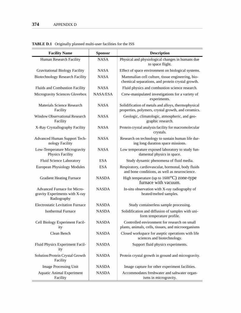
374 APPENDIX D
TABLE D.1 Originally planned multi-user facilities for the ISS
Facility Name Sponsor DescriptionHuman Research Facility NASA Physical and physiological changes in humans due
to space flight.Gravitational Biology Facility NASA Effect of space environment on biological systems.
Biotechnology Research Facility NASA Mammalian cell culture, tissue engineering, bio-chemical separations, and protein crystal growth.
Fluids and Combustion Facility NASA Fluid physics and combustion science research.Microgravity Sciences Glovebox NASA/ESA Crew-manipulated investigations for a variety of
experiments.Materials Science Research
FacilityNASA Solidification of metals and alloys, thermophysical
properties, polymers, crystal growth, and ceramics.Window Observational Research
FacilityNASA Geologic, climatologic, atmospheric, and geo-
graphic research.X-Ray Crystallography Facility NASA Protein crystal analysis facility for macromolecular
crystals.Advanced Human Support Tech-
nology FacilityNASA Research on technology to sustain human life dur-
ing long duration space missions.Low-Temperature Microgravity
Physics FacilityNASA Low temperature exposed laboratory to study fun-
damental physics in space.Fluid Science Laboratory ESA Study dynamic phenomena of fluid media.
European Physiology Modules ESA Respiratory, cardiovascular, hormonal, body fluids and bone conditions, as well as neuroscience.
Gradient Heating Furnace NASDA High temperature (up to 1600°C) zone-type furnace with vacuum.
Advanced Furnace for Micro-gravity Experiments with X-ray
Radiography
NASDA In-situ observation with X-ray radiography of heated/melted samples.
Electrostatic Levitation Furnace NASDA Study containerless sample processing.Isothermal Furnace NASDA Solidification and diffusion of samples with uni-
form temperature profile.Cell Biology Experiment Facil-
ityNASDA Controlled environment for research on small
plants, animals, cells, tissues, and microorganismsClean Bench NASDA Closed workspace for aseptic operations with life
sciences and biotechnology.Fluid Physics Experiment Facil-
ityNASDA Support fluid physics experiments.
Solution/Protein Crystal Growth Facility
NASDA Protein crystal growth in ground and microgravity.
Image Processing Unit NASDA Image capture for other experiment facilities.Aquatic Animal Experiment
FacilityNASDA Accommodates freshwater and saltwater organ-
isms in microgravity.

APPENDIX D 375
D.4 Engineering and Operational Challenges of the ISS
In order to better understand the resources available in the ISS, and more specifically to
identify those resources which set it apart from other types of microgravity facilities, it is
useful to understand which issues have been identified as the most important limiting fac-
tors to the correct utilization of the ISS for research purposes. Reports by NASA
([Durham, 2004], [O’Neill, 1999]) and the NRC ([NRC, 2000], [NRC, 2001], [NRC,
2002]) have identified specific issues related to the ISS which directly affect research. The
resources identified by these issues can greatly benefit research aboard the ISS; limitations
on the availability of these resources limit research opportunities. Because of this direct
relationship, these resources are of special importance to make the best use of the ISS for
research.
The major challenges and issues identified over the past years, directly related to conduct-
ing research on the ISS and listed as recommendations within the mentioned reports, are:
• Communications:
- Increase of communications bandwidth
- Enable video communications
- Establish continuous communications
- Allow crew to communicate directly with principal investigators (PI’s)
- Provide PI’s with direct electronic access to their experimental data
- Develop better communications tools and interaction processes to supportthe multi-national, multi-time-zone utilization of the ISS
• Facilities
- Refine payload computing architectures continuously
• Crew
- Reassess the crew’s activities; allow the crew to take part of daily time-line development
- Reconsider the use of payload-specialists for ISS missions
- Reconsider the posibility to use some components of the ISS as a "safe-haven" to enable the return of a crew of seven
376 APPENDIX D
- Use robotics to increase crew availability
• Approach to Research
- Pursue revolutionary approaches to develop new EVA technologies
- Create an inter-disciplinary research prioritization plan
- Utilize Space Shuttle missions to maintain interest by the science commu-nity until the ISS is ready for operations
- Expand cooperation with international partners to maintain their interest
The recommendations are grouped into four main areas: communications, facilities, crew,
and approach to research. The emphasis on communications and crew among the several
reports is of importance to this thesis, since it indicates that those two special features of
the ISS are relevant to a wide range of ISS users and NASA itself. It is interesting to see
that the recommendations on communications are guided towards creating a stronger and
more direct presence of the investigators in the everyday operations of experiments aboard
the ISS. The recommendations call for the use of real-time video for the PI to be virtually
present in the ISS; they also intend to make data more available to scientists.
The recommendations also put emphasis on the crew availability and expertise. One of the
reports ([NRC, 2002]) goes as far as to argue that NASA reassess the ability to support
seven astronauts, even without a crew return vehicle. Two reports call for the re-evalua-
tion of payload-specialists to become part of ISS crews (when the crew size was expected
to be seven astronauts). All the reports argue that the crew should have an important role
in deciding daily timelines to maximize their productivity. As a whole, the reports put
heavy emphasis on utilizing the crew as best as possible. Minimizing their involvement in
repetitive tasks should be automated, so as to maximize their time involved in conducting
science. It is important to note the difference between simply minimizing the astronaut
time needed for an experiment and minimizing time involved in repetitive tasks. The
reports do not call for the automation of all experiments, rather they call to maximize the
crew time availability to perform productive research.

APPENDIX D 377
The recommendation to "pursue revolutionary approaches to develop new EVA technolo-
gies" also stands out. Through this recommendation, a large number of important scien-
tists not only push for research, they call for the ISS to become a laboratory where
technology matures substantially. The recommendation argues that the experiments con-
ducted aboard the ISS must help to substantially advance the scientific knowledge and
technological capabilities of space flight. As related to the TRLs presented in Chapter 1,
this recommendation calls for technology maturation up to TRLs 6/7/8, demonstrating full
technologies, ready for deployment to their final missions.
Lastly, we can look at the upgrades that NASA has planned for the ISS after the US Core
Complete assembly changes have been decided. In [Durham, 2004] members of the ISS
Payloads Office list the latest infrastructure upgrades to the ISS; a summary of these
upgrades is presented in Table D.2 [Durham, 2004].
Once again, we note that the intended upgrades to the ISS concentrate on the areas of com-
munications and crew. The projects stress the need to transfer data better, both within the
ISS and to ground; increases in bandwidth of up to 30 times are expected. Some of these
upgrades are to help the crew to improve their interfaces with ISS equipment and with
ground personnel, ultimately maximizing their useful time to perform research and mini-
mizing the time they need to perform procedural tasks.
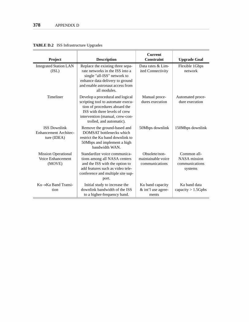
378 APPENDIX D
TABLE D.2 ISS Infrastructure Upgrades
Project DescriptionCurrent
Constraint Upgrade GoalIntegrated Station LAN
(ISL)Replace the existing three sepa-rate networks in the ISS into a
single "all-ISS" network to enhance data delivery to ground and enable astronaut access from
all modules.
Data rates & Lim-ited Connectivity
Flexible 1Gbps network
Timeliner Develop a procedural and logical scripting tool to automate execu-
tion of procedures aboard the ISS with three levels of crew
intervention (manual, crew-con-trolled, and automatic).
Manual proce-dures execution
Automated proce-dure execution
ISS Downlink Enhancement Architec-
ture (IDEA)
Remove the ground-based and DOMSAT bottlenecks which
restrict the Ku band downlink to 50Mbps and implement a high
bandwidth WAN.
50Mbps downlink 150Mbps downlink
Mission Operational Voice Enhancement
(MOVE)
Standardize voice communica-tions among all NASA centers and the ISS with the option to
add features such as video tele-conference and multiple site sup-
port.
Obsolete/non-maintainable voice communications
Common all-NASA mission
communications systems
Ku→Ka Band Transi-tion
Initial study to increase the downlink bandwidth of the ISS
to a higher-frequency band.
Ku band capacity & int’l use agree-
ments
Ka band data capacity > 1.5Gpbs

Appendix E
MIT SSL PREVIOUS MICROGRAVITY EXPERIMENTS
The MIT SSL has designed, built, and operated a multitude of flight experiments in the
past. The lessons learned from these experiments led to the development of the MIT SSL
Laboratory Design Philosophy presented in Chapter 3. The experiments utilized to reach
the philosophy are:
• Mid-deck 0-g Dynamics Experiment (MODE), which flew on STS-48 inSeptember 1991 and its re-flight on STS-62 in March 1994.
• Dynamic Load Sensors (DLS), which flew on MIR for about three years.
• Middeck Active Control Experiment (MACE), which flew on STS-67 inMarch 1995.
• MACE re-flight, which was the first crew-interactive space technologyexperiment conducted aboard the ISS by Expedition 1 in December 2000.
This appendix describes each family of experiments in further detail, with emphasis on the
identification of the features of the MIT SSL Laboratory Design Philosophy.
E.1 MODE & MODE Re-Flight
MODE. The Middeck 0-Gravity Dynamics Experiment (MODE) flew as a facility for
measuring the nonlinear dynamics of fluid slosh and jointed truss structures. Scaled
deployable trusses of different geometries, developed by ABLE Engineering, were excited
at different forcing levels to measure the amplitude-dependent shifts in frequencies and
379

380 APPENDIX E
damping as compared to equivalent 1-g tests. McDonnell Douglas Astronautics collabo-
rated with MIT on this part of the experiments.
The fluid slosh portion of the experiments were conducted to determine the predictability
of nonlinear fluid slosh in 0-g, where surface tension provides the stiffness terms in the
governing equations, based upon models and tests in 1-g where gravity provides the dis-
placement-dependent restoring forces. Silicon oil and water, contained in different geome-
try tanks, were excited at different amplitudes. Both experiments calibrated the ability to
predict 0-g nonlinear behavior from 1-g tests and analyses. [Miller, 1992] and [van
Schoor, 1993] present the objectives and results of the MODE project.
The first laboratory attribute incorporated in MODE was the separation of test-specific
hardware from generic infrastructure. The test-specific hardware consisted of the truss
segments and the tanks that contained the silicon oil and water. Since the objectives of the
tests required that these elements be tested in different configurations, the generic test
equipment was placed in an Electronic Support Module (ESM in Figure E.1 with fluid
tank and shaker attached). This included data storage media, the operator interface, power
amplifiers used to drive actuators, sensor signal conditioning, power conditioning, and
experiment control computers. The ESM was designed to fit into one standard mid-deck
locker. The ESM design was versatile enough to not only test different truss and fluid tank
geometries, but to also allow testing of other as yet unforeseen test-specific hardware on
subsequent Shuttle flights.
Hardware reconfigurability was the second laboratory attribute built into MODE. The
truss segments included two four-bay deployable segments, an erectable segment, and a
rotary alpha joint with operator-selectable friction (Figure E.2). These segments were
attached by the Shuttle crew in different combinations and geometries to allow tests on
increasingly complex and nonlinear systems. Furthermore, a total of four fluid slosh tanks
allowed two different fluids to be tested in tanks with flat and hemispherical bottoms. The
ability of the crew to reconfigure the hardware was instrumental in enabling the test of a
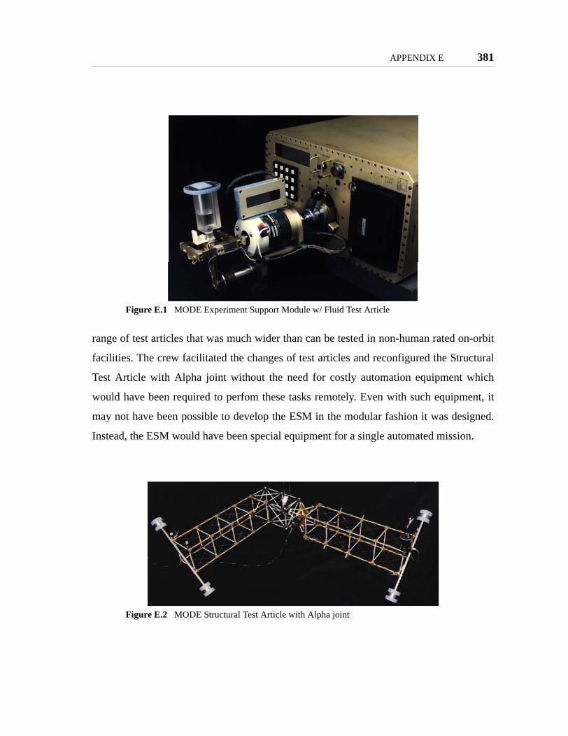
APPENDIX E 381
range of test articles that was much wider than can be tested in non-human rated on-orbit
facilities. The crew facilitated the changes of test articles and reconfigured the Structural
Test Article with Alpha joint without the need for costly automation equipment which
would have been required to perfom these tasks remotely. Even with such equipment, it
may not have been possible to develop the ESM in the modular fashion it was designed.
Instead, the ESM would have been special equipment for a single automated mission.
Figure E.1 MODE Experiment Support Module w/ Fluid Test Article
Figure E.2 MODE Structural Test Article with Alpha joint

382 APPENDIX E
MODE-re-flight. MODE-re-flight flew on STS-62 in March 1994 to perform additional
truss structure tests and initiate the testing of the Dynamic Load Sensors (DLS, pictured in
Figure E.3). DLS consisted of a hand hold, foot restraint, and push pad each instrumented
to measure the forces and torques that a crew member imparts on the vehicle as they move
through the Mid-deck using these devices. This provided a database for quantifying the
loads that crew members would impart on the International Space Station (ISS).
The generic versus specific nature of the MODE design was exploited in two ways during
re-flight. First, the fact that the MODE hardware flown on the original flight was retriev-
able allowed it to be refurbished and reflown to support additional tests at a fraction of its
original cost. Second, MODE-re-flight saw the introduction of a new series of test articles
known as the Dynamic Load Sensors. Since only the DLS test articles, and not the entire
test support equipment, needed to be built, the data collected on the DLS test articles was
acquired very cost-effectively. The MODE design enabled reusability by containing the
generic test equipment in the ESM.
Figure E.3 DLS handhold and foot restraint
APPENDIX E 383
E.2 DLS
The MODE ESM and DLS test articles re-flew on MIR for about three years as a part
NASA's ISS Risk Mitigation program. Re-flight allowed a more extensive database to be
acquired. This allowed crew motion force and torque statistics to be correlated with crew
flight experience as well as with current time on orbit. By testing over weeks to months,
rather than days on MODE-re-flight, crew adaptation time constants could be identified.
[Amir, 1999], [Amir, 2000], and [Newman, 2001] present the methodology and results
obtained over the 40 weeks of DLS operations aboard MIR.
DLS on MIR was the first introduction of extended duration testing in the MODE family
of dynamics and controls laboratories. Extended duration testing allows long time con-
stant dynamics to be identified (e.g., crew adaptation), many cycles of the iterative
research process to be completed, and new test article configurations to be introduced
(e.g., different crew members conducting maneuvers using DLS).
DLS on MIR was the MIT-SSL's first experience with space station operations. Shuttle
science operations are typically characterized by the science team traveling to the NASA
Johnson Space Center and assisting in the operation of the experiment while residing in
one of the Customer Support Rooms. Essentially, the science team needs to travel to
Houston and constantly be "on call" for the duration of the flight. This is an expensive pro-
cess. For DLS on MIR, no such travel was conducted, and the crew and science team were
given days to weeks, rather than minutes or hours, to work through test anomalies. This
more relaxed operational environment allowed anomalies and their solutions to be ana-
lyzed more carefully. Unfortunately, the remote nature of the communication made it dif-
ficult for the science team to clearly understand the issues with the tests, particularly when
the communication was by email and through several layers of flight operations.

384 APPENDIX E
E.3 MACE & MACE-re-flight
MACE. The Mid-deck Active Control Experiment (MACE) flew on STS-67 in March,
1995 to develop dynamics and controls tools for predicting as well as refining robust,
multi-variable control algorithms on systems that cannot be realistically tested in 1-g due
to gravity couplings. [Grocott, 1994], [Campbell, 1995], [Miller, 1996], and [How, 1997]
present the methodologies used to develop and verify controllers during the mission.
[Miller, 1998] and [Campbell, 1999] presents the results of the mission. [Miller, 1995]
present the high-level design goals of MACE to build upon the design of the MODE fam-
ily.
Figure E.4 shows the MACE multi-body platform test article being operated on the mid-
deck of the Shuttle. The test article consisted of a reaction wheel triax attached to a flexi-
ble backbone over a meter and a half in length. A two axis motorized gimbal was attached
at both ends of the backbone to perform pointing and slewing maneuvers. MACE con-
sisted of twenty sensors, nine actuators, an ability for the crew to reconfigure its geometry
into three different shapes, and a system for connecting the MACE ESM with the Shuttle's
Ku-Band communication system.
The Ku-Band Interface System (KIS) gave the ability to downlink test results and uplink
new control algorithms. Five times during the mission, the crew downlinked system iden-
tification and closed-loop test data, the science team refined dynamic models and control
algorithms, and uplinked the new algorithms for test.
MACE continued the design philosophy developed under MODE by separating the test
article from the generic laboratory equipment. Again, an ESM (Figure E.5) was built to
house the generic equipment in a standard mid-deck locker. This ESM, however, included
a high speed real-time computer, an interface for a laptop, and an interface for the Ku-
band system. MACE also incorporated hardware reconfigurability in the test article design
to maximize the science return.

APPENDIX E 385
MACE also introduced a number of important and advanced laboratory attributes. MACE
was designed to be risk-tolerant. Unlike dynamics experiments, control experiments have
the potential to result in unstable behavior leading to large amplitude motion. The team
realized that since the technology being investigated was control and that the desire to
explore the limits of control capability dramatically increased the probability that instabil-
ity would occur, safety assurance through software was not an option. Instead, the MACE
team took the approach of ensuring that instability could not break the hardware and that
Figure E.4 MACE operations on shuttle mid-deck
Figure E.5 MACE Experiment Support Module

386 APPENDIX E
the crew member was provided with a switch that could immediately cut off power to the
test article. These features allowed the boundaries of instability to be explored using a test
article that was tolerant of the associated risk. Few if any other on-orbit systems could
view unstable behavior as routine operation.
Unlike the MODE laboratory, MACE allowed the science team to change the software
during the mission. Software reconfiguration gives the researcher many more degrees of
freedom that can be manipulated to alter the conditions of the test. Software that performs
dynamic characterization of the test article can be changed in order to investigate unfore-
seen phenomena in more detail. Control algorithms can be modified based upon models of
the unforeseen phenomena. Sensor and actuator groupings can be changed to explore new
disturbance and performance topologies. Furthermore, it allows experimental research
into methodologies that facilitate on-orbit validation for precision space systems that can-
not be accurately tested prior to launch.
The MACE design was the first in the MODE family to exploit human observation and
manipulation of the test. Through training and on-orbit documentation, the crew devel-
oped the capability to identify, describe, and alter test conditions. In the event that the
crew observed unexpected motion of the test article, they described the motion to the sci-
ence team. A nomenclature was developed to allow the crew to describe the behavior.
The crew was asked to estimate whether it exhibited broad or narrow-band frequency con-
tent, the frequency range in which the dominant motion occurred, and any directional
preference in terms of an agreed upon coordinate system.
Since MACE verbal communications only occurred twice a day and data down-links
occurred once a day, the crew then needed the ability to manipulate the test sequence if a
clear instability or hardware failure was observed. The training and on-orbit documenta-
tion allowed the crew to maximize the number of successful algorithms tested between
communication opportunities. To this end, the Flight Data File, used by the crew to guide
them through experiment operations, contained families of algorithms. Each family corre-

APPENDIX E 387
sponded to a specific geometric axis of motion, sensor-actuator suite, control design
approach, and designation as to whether that family was a primary family or a backup.
Each family consisted of six to eight algorithms or individual tests. Each succeeding algo-
rithm would have slightly higher control gain.
Backup families would be tested if its corresponding primary family exhibited hardware
problems (e.g., failed actuator or sensor). This allowed them to explore the same control
features while isolating failed hardware from the control.
When a clear instability was observed during two successive tests within a family, the
crew could ignore all remaining higher gain algorithms in that family. This allowed the
crew to maximize science productivity.
The last important attribute introduced in MACE was the facilitation of the iterative
research process. The science team used the verbal observations communicated by the
crew to prepare a plan of attack for the next control redesign phase that would start after
the next down-link of data. In addition, they would assist the crew in re-planning their
next sequence of tests as well as selecting data files that should be down-linked during the
next opportunity. Data down-links occurred once every one to two days. Dynamic charac-
terization data was used to generate models and closed-loop response data was used to
alter control parameters. During a single crew sleep period, the science team built mod-
els, developed new families of control algorithms, and wrote updates to the Flight Data
File. The latter two were up-linked with the morning mail. The existence of the KIS inter-
face for (up)down-link, crew observations and test sequence manipulation, and science
team facilities were instrumental in shortening the research "question & answer" cycle
time to one day.
One day cycle time was a little too short. The team basically had enough time to regurgi-
tate algorithm refinements in response to features observed by the crew and in the data.
Allowing several days to weeks to digest the downlinked test results and develop updates
to algorithms would allow a more methodical approach to posing new research questions

388 APPENDIX E
and putting test plans in place to address those questions. Clearly, this requires the labora-
tory to reside on orbit for longer periods of time.
MACE-re-flight. On MACE's second flight, it was launched to the International Space
Station in September 2000. Operations started in December of that year with the arrival of
the Expeditionary One Crew making MACE-re-flight the first crew-interactive experi-
ment on ISS. Figure E.6 shows operations of the MACE article inside the ISS US Node.
MACE-re-flight was a collaborative effort between the Air Force Research Laboratory
(AFRL) and the MIT-SSL. Each brought with them a team of researchers studying
dynamics and controls technologies ranging from neural networks to nonlinear dynamic
characterization to adaptive reaction wheel isolation. Modifications for re-flight included
an upgraded real-time control computer and operating system, upgraded data storage
media, and meter long flexible appendages attached to the gimbal faces giving the test
article an appearance of a free-floating, multi-link robot. MACE-re-flight returned to the
ground in August 2001. [Blaurock, 1999] presents the modeling of MACE-re-flight prior
to deployment, while [Yung, 2001] uses the results of the mission.
The laboratory attribute first featured in MACE-re-flight was opening the laboratory to
multiple investigators. A number of government research agencies, industries, and aca-
demic institutions participated in MACE-re-flight. Unfortunately, due to the early stage of
ISS assembly, data downlink and crew time were limited. This severely limited the itera-
tive research process.

APPENDIX E 389
Figure E.6 MACE operations aboard the ISS

390 APPENDIX E

Appendix F
SPHERES AVIONICS DESIGN
Please see SSL report # 6-05.
391

392 APPENDIX F

Appendix G
SPHERES SOFTWARE DESIGN
Please see SSL report # 6-05.
393

394 APPENDIX G

Appendix H
SPHERES COMMUNICATIONS
Please see SSL report # 6-05.
395

396 APPENDIX H

Appendix I
SPHERES EXPERIMENTAL RESULTS
I.1 Results at the MIT SSL
The SPHERES facilities have operated at the MIT SSL since the Spring of 2000 utilizing
the original prototypes. During this time research was done on the effects of communica-
tions on formation flight systems (2000), formation flight algorithms (2000+), docking
algorithms (2002+), system identification and fault detection (2003+), tether prototypes
(2003+), and began research to support the Mars Orbiting Sample Return mission
(2004+). Table I.1 summarizes the research conducted at the MIT SSL facilities in Cam-
bridge, MA since 2000.
TABLE I.1 Research conducted at the MIT SSL
Research Year Application Guest ScientistF.F. Communications 2000 DSS
F.F. Control 2000 TPF JPLDocking Control 2002 + Orbital Express
(DARPA)Mass ID / FDIR 2003 + Modeling Ames
Tethers 2003 + SPECS GoddardMOSR 2004 + Mars Sample
Return
397
398 APPENDIX I
The tests on communications during 2000 provided an initial understanding of simple
communications issues regarding formation flight. The goal of the tests was to determine
the effects between high frequency transfer or state information and the size of the state
being transferred. To this purpose five experiments were setup; a number of tests for each
setup was performed. The final results evaluated the difference in performance between
the different experimental setups. [Saenz-Otero, 2000]
Development of formation flight algorithms began in the Spring of 2000 in preparation for
tests aboard the KC-135 reduced gravity airplane (RGA) and later on for tests at the
MSFC Flat Floor. These tests included control of one, two, or three degrees of freedom
between two spacecraft (2000+, for the RGA) and formation flight of three and five space-
craft (2003+, for the MSFC Flat Floor). [Hilstad, 2003], [Kong, 2004a]
The formal development of docking algorithms began during 2002 [Nolet, 2004]. While
previous tests conducted sets of maneuvers that resulting in docking, these did not follow
the full scientific process, but were rather a demonstration of the facility's capabilities.
Work with NASA Ames Research Center provided the first complete cycle of remote
investigation using SPHERES. Through 2003 and 2004 researchers at NASA Ames paired
with a member of the SPHERES team to conduct experiments at the MIT SSL while they
worked from their home facility. The Ames investigators developed their own algorithms
in house, and incorporated them into the SPHERES Core using the provided API. For sev-
eral months the algorithms were sent electronically to MIT, debugged over a few days,
and then experiments conducted. Once the algorithms were close to mature, the Ames
investigators visited the MIT SSL facilities to finalize their design. After the final design
was complete, the researchers returned to NASA Ames, and the SPHERES team con-
ducted further tests to obtain more data. The Ames algorithms were also tested aboard the
RGA. [Berkovitz, 2003]
Development of tether mechanism that utilize the SPHERES satellites’ expansion port
began at the MIT SSL during 2003. Prototype designs were developed and used both at

APPENDIX I 399
the MIT SSL facilities and at the MSFC Flat Floor. These prototypes utilize power and
signals from the SPHERES expansion port to incorporate the tether mechanism as an inte-
gral part of the satellite. Development at the MIT SSL has provided the knowledge neces-
sary to create medium fidelity models of tethered spacecraft systems; these models were
utilized for tests in the MSFC Flat Floor.
Research to support the Mars Orbiting Sample Return mission (MOSR) began in 2004 by
the creation of an initial design of a capture mechanism and the development of algo-
rithms to simulate impact forces. Tests at the MIT SSL include the development of control
algorithms that ensure a SPHERE satellite will impact a target in a fixed location at a pre-
specified velocity and angular rate, representative of what is expected in the actual space
capture. At this point one substantial thread of iterations has occurred to present the
MOSR team with a proof-of-concept on the use SPHERES to support their research.
I.2 Results aboard the KC-135
Both the prototype and the flight units have been used for experiments aboard the KC-135
reduced gravity airplane over the course of six weeks. Table I.2 presents the month and
year of each flight week, as well as the type of satellites (prototype or flight equipment)
used in each flight. A short description of each week's research is presented next.
TABLE I.2 KC-135 flight weeks and satellites operated
Dates Prototype FlightFeb. 2000 2 -Mar. 2000 2 -Oct. 2001 2 -July 2002 2 1Feb. 2003 - 3Nov. 2003 - 2

400 APPENDIX I
February 2000
The February 2000 flights were performed as a proof-of-concept flight for the SPHERES
satellites. This week of flights did not concentrate on the development of control algo-
rithms, but rather on the thorough testing of all the SPHERES systems. These tests were
the first time that the SPHERES hardware was exposed to a 6DOF environment, and
therefore the first time that a controller had to operate more than two thrusters at a time. It
was also the first time that the operators were required to use the interfaces and control
software in a stressful environment. Table I.3 summarizes the tests conducted with the
prototype units during the February 2000 flights.
The resulting information led to the first major iteration in the design of the SPHERES
facilities. The satellites were upgraded prior to the next flight to increase the reliability of
the propulsion, communications, and power systems, which presented failures during the
February 2000 flights. The graphical user interface went through its first iteration: the type
of data presented changed (presented more processed data, instead of raw information),
although the type of interface remained basically unchanged.
TABLE I.3 February 2000 flight results
Feb. 2000 Test TopicsExperiment Repetitions
Flight 1 1 DOF Open Loop Rotations 201 DOF Open Loop Translations 20
Flight 2 1 DOF Open Loop Rotations 40Flight 3 1 DOF Closed Loop Rotations 20
3 DOF Rotation Damp 152 SPHERES Rotation Comparison 5
Flight 4 3 DOF Closed Loop Rotations 202 SPHERES Rotation Comparison 20
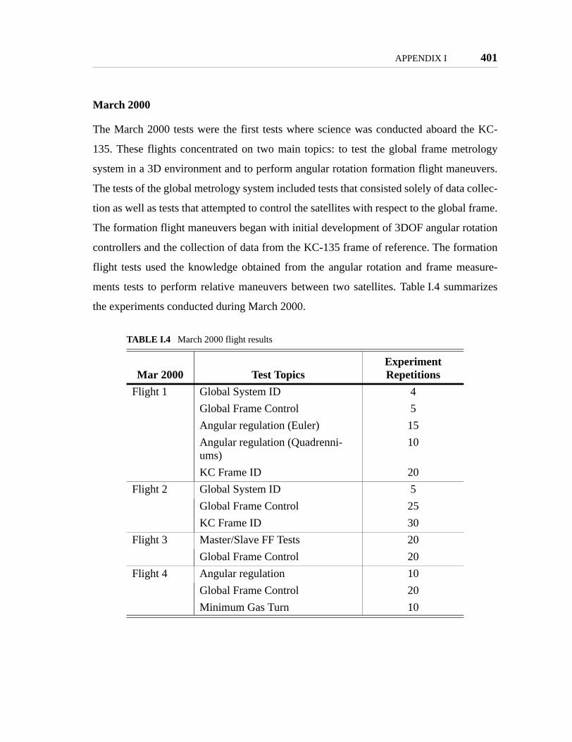
APPENDIX I 401
March 2000
The March 2000 tests were the first tests where science was conducted aboard the KC-
135. These flights concentrated on two main topics: to test the global frame metrology
system in a 3D environment and to perform angular rotation formation flight maneuvers.
The tests of the global metrology system included tests that consisted solely of data collec-
tion as well as tests that attempted to control the satellites with respect to the global frame.
The formation flight maneuvers began with initial development of 3DOF angular rotation
controllers and the collection of data from the KC-135 frame of reference. The formation
flight tests used the knowledge obtained from the angular rotation and frame measure-
ments tests to perform relative maneuvers between two satellites. Table I.4 summarizes
the experiments conducted during March 2000.
TABLE I.4 March 2000 flight results
Mar 2000 Test TopicsExperiment Repetitions
Flight 1 Global System ID 4Global Frame Control 5Angular regulation (Euler) 15Angular regulation (Quadrenni-ums)
10
KC Frame ID 20Flight 2 Global System ID 5
Global Frame Control 25KC Frame ID 30
Flight 3 Master/Slave FF Tests 20Global Frame Control 20
Flight 4 Angular regulation 10Global Frame Control 20Minimum Gas Turn 10

402 APPENDIX I
October 2001
The February and March 2000 flights both demonstrated that one of the most challenging
sub-systems in the SPHERES testbed was global metrology. While several tests during
2000 demonstrated the ability for inertial control using the gyroscopes, SPHERES had not
been able to control consistently with respect to the global metrology system. Therefore,
in what can be considered a long-term iteration, the SPHERES team updated the global
metrology system to experiment once more in the KC-135.
Table I.5 summarizes the experiments conducted on October 2001. The majority of the
October 2001 tests concentrated on testing the global metrology system. Having learned
that the SPHERES satellites lacked enough authority to perform complex maneuvers in
the KC-135 frame (mostly due to airplane turbulence), the new tests concentrated on
1DOF maneuvers and station keeping. Throughout the week tests were run and data ana-
lyzed. The data included both free-float data to determine if the global metrology system
had enough bandwidth to capture the motion of the satellites during turbulence, as well as
data when control was attempted. Data analysis indicated further need to refine the metrol-
ogy system before being able to determine if the units had enough authority. During the
last day of flights the global frame control was mostly limited to attitude control (with
respect to the global frame), which was deemed possible through analysis of data earlier in
the week.
The second set of tests was to calculate the inertia of the satellites. This information was
obtained over two days, with data analysis in between to ensure the right data was
obtained. This analysis time was essential, since it led to new tests that collected data not
considered necessary on the first day. The data helped develop the attitude control tests of
the last day of experiments.
July/August 2002
These flights carried out the first 6DOF tests of the flight units. The first flight unit was
tested in this environment for full operations, especially for repeatability and reliability of

APPENDIX I 403
its sub-systems. While not a direct part of the science, it demonstrated the success of a
major design iteration from the prototype units to the flight units. The flight unit was used
in the first flight training videos for astronauts. These videos were improved over future
flights.
The science conducted in these flights, using the prototype units, once again concentrated
on the global metrology system, but also included a substantial amount of docking control.
Lessons were learned from past experiences with the global metrology system, and the
experiments were modified to better fit the environment of the KC-135. The global
metrology tests during these flights were conducted solely as relative flight between the
units, attempting to maintain formation as a system. The total system was not controlled to
maintain a certain position or attitude with respect to the global frame; rather, the units
were required to maintain formation. The tests were more successful than in the past, but
the limited test time of 20 second prevented substantial data from being collected. A sum-
mary of these tests is presented in Table I.6.
The success of the relative motions in the initial days led to the development of docking
controllers which, as with the past global system controllers, performed docking maneu-
vers controlling only the distance between the units, and not the absolute position of the
system. These tests completed successfully over a few parabolas. The relevant part of
TABLE I.5 October 2001 flight results
Oct. 2001 Test TopicsExperiment Repetitions
Flight 1 Inertia Measurement 6Closed Loop Inertial Control 12Global Frame Control 20
Flight 2 Hardware Tests 10Global Frame Control 30
Flight 3 Inertia Measurements 10Global Frame Control 30
Flight 4 Global Frame Control 40

404 APPENDIX I
these tests is that they utilized the iterative nature of SPHERES over a wide range of time
frames: the success of the algorithms was due to the better understanding of the KC-135
environment over multiple flights, to the development of the relative motion controllers,
and to the ability to iterate over one day on the docking algorithms.
February 2003
The February 2003 experiments were conducted solely with the flight units, and the tests
were geared mostly to conducting small amounts of science each day. There were three
main areas of study during these flights: high level system identification via one-degree-
of-freedom maneuvers, to later be used in FDIR algorithms; high-speed collection of iner-
tial data to fully identify the thrusters with the goal to create a B matrix in the standard
state-space equations, while also helping fully identify the dynamics of each satellite and
the behavior of the inertial sensors; and control within the global frame was once again
attempted in two manners, one setup using the KC-135 frame, and another setup using the
ultrasound system only between units, without referencing the KC-135 frame at all.
Table I.7 summarizes the tests conducted during February 2003.
The tests suffered a setback during the second flight, when the communications system
failed for the majority of the flight and no data collection was possible. The SPHERES
designed hardware did not fail; it was the COTS laptop computer that served as a control
station which failed. While this was a setback of the individual flight, it provided direct
TABLE I.6 July/August 2002 flight results
Jul./Aug. 2002 Test Topics
Experiment Repetitions
Flight 1 Global Frame Control 40Flight 2 Global Frame Control 40Flight 3 Global Frame Control 20
Docking 20Flight 4 Global Frame Control 20
Docking 20
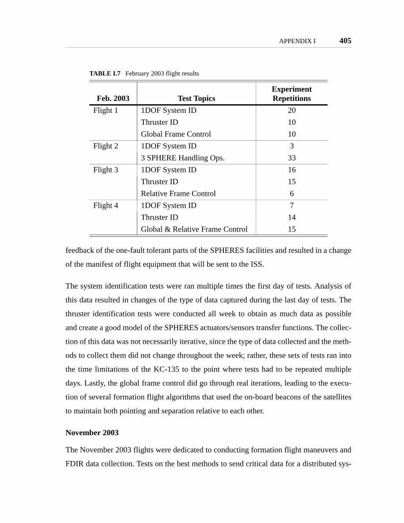
APPENDIX I 405
feedback of the one-fault tolerant parts of the SPHERES facilities and resulted in a change
of the manifest of flight equipment that will be sent to the ISS.
The system identification tests were ran multiple times the first day of tests. Analysis of
this data resulted in changes of the type of data captured during the last day of tests. The
thruster identification tests were conducted all week to obtain as much data as possible
and create a good model of the SPHERES actuators/sensors transfer functions. The collec-
tion of this data was not necessarily iterative, since the type of data collected and the meth-
ods to collect them did not change throughout the week; rather, these sets of tests ran into
the time limitations of the KC-135 to the point where tests had to be repeated multiple
days. Lastly, the global frame control did go through real iterations, leading to the execu-
tion of several formation flight algorithms that used the on-board beacons of the satellites
to maintain both pointing and separation relative to each other.
November 2003
The November 2003 flights were dedicated to conducting formation flight maneuvers and
FDIR data collection. Tests on the best methods to send critical data for a distributed sys-
TABLE I.7 February 2003 flight results
Feb. 2003 Test TopicsExperiment Repetitions
Flight 1 1DOF System ID 20Thruster ID 10Global Frame Control 10
Flight 2 1DOF System ID 33 SPHERE Handling Ops. 33
Flight 3 1DOF System ID 16Thruster ID 15Relative Frame Control 6
Flight 4 1DOF System ID 7Thruster ID 14Global & Relative Frame Control 15

406 APPENDIX I
tem were also conducted. Table I.8 summarizes the tests conducted during this week of
experiments. Since the formation flight maneuvers were only relative, the global metrol-
ogy system was not used during this week of flights.
A formation flight system would follow each of these steps in sequence: lost in space
maneuver, beacon tracking to capture the other unit, and then perform formation flight or
docking. Due to the limited 20 seconds experiment test time, the different maneuvers of a
formation flight deployment sequence were separated and tests conducted individually.
The data of each individual test were collected to demonstrate how the different algo-
rithms create a formation flight system. The tests began with the demonstration over two
days of the ability of two units to track their angular position with respect to each other
(beacon track). Docking algorithms were also tested, to demonstrate control of separation
between units. The "Lost in Space" algorithms demonstrated different ways in which two
TABLE I.8 November 2003 flight results
Nov. 2003 Test TopicsExperiment Repetitions
Flight 1 Beacon Track 9Docking 6Lost in Space 5Inertia ID 7Distributed Control Architecture 10
Flight 2 Beacon Track 20Distributed Control Architecture 10Inertia ID 10
Flight 3 Docking 11Lost in Space 8Distributed Control Architecture 10Inertia ID 10
Flight 4 Docking 12Lost in Space 17Inertia ID 10

APPENDIX I 407
satellites, deployed in space with a random attitude, can find each other by following a
prescribed 3DOF rotation; the goal was to balance fuel consumption and duration of the
maneuver. The ability of the SPHERES software to separate the tests into these steps
allowed significant tests to be conducted in the short test-time of the KC-135.
I.3 Results at the MSFC Flat Floor
The Marshall Space Flight Center Flat Floor provides an environment similar to that of the
MIT SSL: 3DOF tests under 1g conditions utilizing air carriages. But the MSFC facility
provides a substantially expanded operational area of over 10 meter square (30 feet
square). This extended area allows scientists to perform tests with up to five SPHERES,
which is not physically possible at the MIT SSL; it enables more realistic lost-in-space
demonstrations and docking maneuvers; and it allows the use of tethers several meters in
length. The SPHERES team took advantage of these three options during two campaigns:
three days in June 2004 and five days during December 2004. Tests included demonstra-
tion of formation flight maneuvers with two, three, and five spacecraft relevant to the TPF
mission, docking algorithms over large separations, and tethered formations with two and
three satellites. Table I.9 summarizes the tests conducted at the MSFC Flat Floor.
The formation flight maneuvers consisted of satellite deployment and tracking of a circu-
lar path. Tests with two units involved constant and expanding separations of 0.5m, 1m,
and 1.5m to demonstrate both deployment and image capture maneuvers. The three and
five satellite tests used constant separations to demonstrate formation flight algorithms.
TABLE I.9 MSFC flat floor experiments
Week 1 Week 2
Algorithm Day 1 Day 2 Day 3 Day 1 Day 2 Day 3 Day 4 Day 5TPF Rotations
DockingTether

408 APPENDIX I
The three unit tests utilized a separation of 1m between units, for a total array separation
of 2m; five units formations maintained constant separations of 1m, for an array size of
4m.
The docking experiments demonstrated docking maneuvers with a free rotating target; this
was achieved incrementally through four steps over two days. The first experiment con-
sisted of 2 units performing a cooperative docking maneuver starting about 1.5m apart,
with the chaser unit pointing in a random direction. The second configuration was close
proximity tracking of a free rotating target to tune the control algorithm which controls
movement in the tangential direction. Next, docking maneuvers with uncooperative tar-
gets were performed. For the third set of tests, the target was slowly drifting but not rotat-
ing; this allowed tests of the control algorithms in the presence of perturbations caused by
plume impingement on the target. Finally, multiple docking maneuvers with a slowly
rotating target were successfully performed.