Design Parameters and Measured Perfornlance of the IRAM...
25
Design Parameters and Measured Perfornlance of the IRAM 30-m Millimeter Radio Telescope Baars, A. Greve, H. Hein D. Morris, J. Penalver, C. Thurn IRAM N°298 Proceedings IEEE : Design and Instrumentation of A ntennas for Deep Space Telecommun2:cations and Radio Astronomy 1993
Transcript of Design Parameters and Measured Perfornlance of the IRAM...

Design Parameters and Measured Perfornlance of the IRAM 30-m
Millimeter Radio Telescope
J.'V.~1. Baars, A. Greve, H. Hein D. Morris, J. Penalver, C. Thurn
IRAM N°298
Proceedings IEEE : Design and Instrumentation of A ntennas for
Deep Space Telecommun2:cations and Radio Astronomy 1993

Design parameters and measured performance of the IRAM 30-m Millimeter Radio Telescope.
1. SMT Observatory, Steward Observatory, Univ. of Arizona, Tucson, AZ 85721, USA 2. IRAM, Avenida divina Pastora 7, Nucleo Central, 18012 Granada, Spain 3. IRAM, Domaine Universitaire, 38406 St. Martin d'Heres, France 4. Max Planck Institut fur Radioastronomie, Auf dem HUgel 69, 5300 Bonn 1, Germany
Abltract
The "Millimeter Radio Telescope" (MRT) is operated by the Institute for Radio Astronomy in the Millimeter range (IRAM) and is located at 2850 m altitude in the Sierra Nevada, near Granada, Spain. It is a reflector antenna of 30-m diameter with a surface accuracy of 0.08 mm and a pointing accuracy of better than 2 arcseconds. The telescope is equipped with sensitive receivers for the atmospheric windows between 0.8 and 7 mm wavelength. We describe the optics lay-out of the receiver and calibration system, which allows simultaneous observations at a number of frequencies. The special design aspects of the antenna, in particular the control of thermal deformations and the achievement of a high reflector and pointing accuracy are described. We compare the design computations with the characteristics of the telescope, derived from several years of operation and optimisation. The success of the design is demonstrated by our observational experience. We conclude the paper with a short review of some of the astronomical results obtained with the telescope.
Accepted for publication in a Special Issue of the Proceedings IEEE:
"Design and Instrumentation of Antennas for Deep Space Telecommunications and Radio Astronomy"
1

1. Introduction.
After the discovery of carbon monoxide (CO) in the Galaxy by its spectral line radiation at 115 G Hz [1], millimeter wavelength radio astronomy was quickly established as an important branch of observational astronomy. Owing to insuffi cient accuracy of the available radio telescope reflectors, early observations could be done by only a few telescopes of 3 - 12 m diameter. Soon it became clear that higher sensitivity, better angular resolution and observations at higher frequencies, in particular of higher transitions of CO, were needed. This posed a challenge for the design of large and highly accurate reflector telescopes for the short millimeter wavelength region.
The theoretical basis for the design of accurate reflector antenna structures is to be found in the principle of homology, developed in the mid sixties by von Hoerner [2J. It was first applied in practice in the early seventies for the design of the Effelsberg radio telescope, which has a diameter of 100 m and can be used at frequencies as high as SO GHz. Based on this success, the Max-Planck-Institute for Radio Astronomy (MPIfR) developed plans for a large and accurate telescope for the millimeter wavelength range. The primary specification was a reflector surface accuracy of 0.1 mm. From preliminary studies it emerged that a reflector diameter of 30 m would be technically and financially feasible. Thus the M illimeter Radio Telescope (MRT) was designed in the late seventies and the construction began in 1980.
Millimeter waves are strongly absorbed by the water vapour of the earth's troposphere. To minimize this effect, the telescope is located at 28 SO m altitude on Pico Veleta, near Granada in the Sierra Nevada of Southern Spain (Fig. 1), where the column of precipitable water vapour, determined during site tests [3], and confirmed by recent IR- hygrometer measurements [4 J and mm-wave atmospheric transmissivity, is often less than 2 mm, particularly in winter. The design of the telescope had to account for occasional strong winter storms with severe icing conditions. Since 1985 the telescope has been in full astronomical operation, and a large amount of astrophysical results has been obtained. Also during more than seven years of operation, much has been learned about the behaviour of the instrument under variable environmental conditions at a high mountain site. Efforts for improvement of its characteristics are continuously being made.
Several papers have been written on the technical aspects of the telescope, to which we shall refer at the appropriate place below. In this paper we give special attention to a comparison of the calculated design parameters of the telescope with those achieved in practice (see also [5J).
2. Optics of the antenna and receiver layout.
The geometry of the MRT is summarized in Table 1, and a cross-section of the antenna is shown in Fig. 2. The telescope is a Cassegrain system with paraboloidal main reflector and hyperboloidal secondary reflector. The cross section of the quadrupod, which supports the secondary reflector, and the central blocked part of the secondary reflector have been shaped so as to minimize backscatter which could cause baseline ripple in spectroscopic observations. For operational flexibility and ease of maintenance, we specified a spacious and easily accessible cabin for the receiver frontends between the two elevation bearings, closely behind the vertex of the main reflector. The radiation from the secondary reflector is guided by two flat mirrors (M3 and M4 in Fig. 3), positioned on the elevation axis,
2

to the so-called Nasmyth-focus, which is fixed with respect to the receiver cabin. Therefore the receivers need not move in elevation angle, while they rotate in azimuth with the telescope.
The layout of the receivers and the "quasi -optic s" feeding them is sketched in Fig. 3. A total of 7 coherent receivers and 2 bolometer systems are located in the cabin, leaving an additional free place for a "guest receiver" (Fig. 4). The characteristics of the present set of receivers are assembled in Table 2, while the multiple receiver options are shown in Table 3. The receivers are aligned to within 2-3" on the sky and to within a few tenths of a millimeter in focus.
A useful feature of the system calibration is the availability of permanent loads at liquid nitrogen and ambient temperature. At each calibration, typically occuring every 20 min, the receiver gain and atmospheric transmissivity are determined by a short measurement of the ambient and cold load, as well as the atmospheric emission. This enables us to reach an overall accuracy of the spectroscopic calibration of about 10%. The calibration of the flux density of continuum sources is tied into a net of standard sources (quasars, compact HII-regions, planetary nebulae), which are regularly monitored.
The capability to wobble the subreflector is extensively used; some 40 million cycles have been made to date. This is essentially a variation on the Dicke radiometer concept, in which output fluctuations caused by the system, and here particularly by the atmosphere, are suppressed by synchronous detection of the signal from two slightly different directions. During spectroscopic observations the system runs at 0.25 Hz, while continuum observations, being more sensitive to atmospheric fluctuations, are done at 0.5 - 2 Hz. In spectroscopy this technique usually produces flat baselines. Under good atmospheric conditions the performance is noise limited, without baseline instabilities even in long (5h) integrations. This has contributed greatly to the success of the MRT in extragalactic spectroscopy and mapping of extended sources. With improved receiver sensitivities now available, a faster wobbler would be advantageous for continuum observations to suppress the atmosphere more completely.
3. The design of the structure and the renector panels.
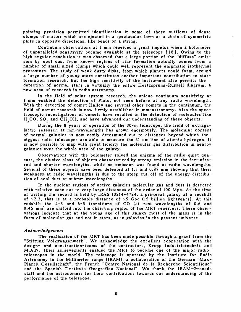
The design aim was a homologous structure [2,6 J. By this we mean that the graVitational deformations, which vary with elevation angle, transform the original paraboloidal reflector into another paraboloid with an equally good fit, but allowing a change in the best-fit focal point. The structural design problem was that of finding a practically realizable and economical structure between a large number of equally soft support points for the reflector panels and the two ha rd points, where the entire moving structure is supported at the elevation bearings. The quadrupod which supports the subreflector was incorporated in the overall design for the first time, and the optimisation simultaneously minimized both the reflector deformation and the variation in pointing direction [7J. This helped to minimize the influence of wind, especially serious for this telescope at its exposed location. The geometric layout of the elevation structure did not allow symmetry below the reflector support truss structure to be maintained. Here a massive square yoke, with rearward counterweight arms, rotates on two elevation bearings (Figs. 2, 5). A cone-shaped extension from the four corners of the yoke, realized by plate elements, is terminated in a disk of 14 m diameter supporting the truss structure of 40 radial members. The elements of the cone are so dimensioned that the disk remains flat and round at all elevation angles, thereby forming an equal-softness support for the symmetrical truss section, which in itself behaves homologously. A decisive impro
3

vement in the residual deformation has been achieved by a lateral displacement of the counterweights. The resulting bending moment in the yoke compensates part of the gravity loads. The remaining gravitational deformation of the MRT in horizon and zenith position, calculated from an assumed surface adjustment angle of 55
0 ,
is shown in Fig. 6. The detailed specification, along with the actually achieved performance, is summarized in Table 4.
In designing the MRT we placed equal importance on a high pointing and tracking accuracy as on the reflector accuracy. At the shortest wavelength of 1 mm the beamwidth is 10", requiring a pointing accuracy of 1-2". The exposure to the environment and in particular the survival conditions under storm and icing conditions dictated a massive structure, the stiffness of which could be exploited to obtain the required high pointing accuracy. The influence of gusty winds on the pointing is minimized by the use of a fast and accurate servo-control system for the telescope pointing. The MRT control system has a 6 ms cycletime and uses both position and velocity of the telescope axes and of the drive motors as input parameters. It is possible to maintain a tracking stability of 1" in winds of 10 m/s.
The surface of the reflector consists of 420 panels, each about 2 m2
in area and arranged in 7 concentric rings. They are made of streched aluminium skins, bonded to aluminium honeycomb of 40 mm thickness. Two panels each are supported on a stiff intermediate frame by 30 adjustable, hinged bolts. The average rms-error of the panelunits is 26 llm, achieved by adjustments on a 3D-measuring machine of 5 llm measurement accuracy (Fig. 7). A thin coating of white TiO paint reflects most of the infalling solar radiation, while effectively cooling th~ panel by infrared radiation, resulting in a difference between panel temperature and ambient of typically not more than 5-10 K.
Severe icing conditions occasionally occur at the telescope site. To prevent damage to the structure, the entire telescope is covered with insulating panel~ (see also next section). Embedded heating elements with a capacity of 100 W 1m are switched on during icing to keep the telescope free of ice. The reflector panels can be heated from the rear for the same purpose. A power of "'800 kW may be used under icing conditions. With some imagination one could desc ribe the cladding as the tightest astrodome possible; it is attached directly to the telescope.
4. Temperature control and model calculations.
Considering the dimensions and operational wavelength of the MRT, deformations resulting from gradients and inhomogeneities in temperature were predicted to be at least as severe as those caused by gravity. We gave this aspect full attention from the start of the design by performing thermal model calculations, though of a simplified nature in the initial stages. To reduce thermal deformations to an acceptably low level of a few tens of micrometers, the calculations indicated that the structure should be homogeneous in temperature (spatial and temporal gradients) to about 1 K. It was also found that for a fully exposed telescope this condition could only be achieved by active thermal control.
The following special measures have been incorporated to mtntmtze the thermal influence of the environment. The MRT is completely covered with insulating panels, Le. the reflector backup structure, yoke, quadrupod, secondary focus cabin and the concrete pedestal. All outer surfaces are painted with a heat reflecting TiO paint. The temperature of the backup structure is actively controlled by circulatiftg climatized (heated or cooled) air, by which a temperature homogeneity of "'0.5 K is achieved, as well as equality to "'1 K with the temperature of the yoke. This massive and thermally slow structure is used as temperature reference.
4

Similarly, the quadrupod is actively controlled to within 0.5-1 K of the yoke temperature by a liquid (freon) heat exchanger running in pipes encircling the legs.
Under most conditions the thermal control system operates according to the specifications [8,9]. Figure 8 shows the temperature homogeneity of the backup structure for the year 1988, while Fig. 9 illustrates the difference between the temperature of the unregulated yoke and the controlled reflector backup structure. It demonstrates the technical feasibility of controlling the temperature of about 200 tons of steel, assembled in a complicated geometrical arrangement.
We have also found [8,9,10J that it is possible to construct correct thermal models for geometrically intricate structures under a variety of environmental conditions. However, there still is room for improvement, particularly in better understanding, and perhaps controlling, the radiative interaction between the telescope and the environment. In any case our experiences with the MRT have provided guidelines for future thermal designs of antenna structures.
5. Reflector measurement - radio holography.
The reflector panels must be set to the prescribed paraboloid with an accuracy of 50 ~m. We used several methods to reach the required accuracy. Initial alignment was achieved with a modified "theodolite-tape" method, which resulted in an overall reflector accuracy of 120 ~m [llJ. Subsequently we applied radioholography, first .with a full phase system at 22.3 GHz, using a celestial maser water vapour source [12], later with a phase-retrieval system at 90 GHz with the aid of an earthbound transmitter in the nearfield [13] and most recently at 39 GHz, using the Italian satellite ITALSAT. Several iterations of measurement and adjustment of the panels were carried out. All panel adjustments were corrected for the calculated deformations between the measuring elevation angle and elevation 50
0 , where we prefer to have the best possible surface. The present rms
reflector surface accuracy as estimated from the holography measurements, aperture efficiency values and the observed levels of the error pattern, lies in the range 65-85 ~m. The angular width of the error beam, being inversely proportional to the scale length of the reflector errors, indicates that there is still a significant contribution to the overall error from large scale misalignments. Efforts are continuing to reduce this effect. The history of the reflector measurements and following panel adjustments has been summarized in [14].
6. Pointing behaviour and calibration.
The pointing and tracking specification of the MRT is 2" absolute error. This is required for reliable observations at the important wavelength of 1.3 mm, where the beamwidth is 12". The stiff construction of the mount and the advanced servo-control system enable us to achieve this goal in winds of up to 10 m/s.
The absolute pointing of the telescope in elevation and azimuth is obtained from a model that describes the behaviour of an alt-azimuth mount, its homologous deformation, the refraction of the radio beam including a third order term, a clock error, and the ellipticity of the axis encoders, by a set of 9 parameters for each axis. These parameters are derived by observations at 3 mm wavelength of anumber of strong radio sources with well known positions, very small sizes and distributed over the sky, mostly quasars and galactic SiO maser sources. On the basis of such pointing observations, we established that the adopted model described the behaviour of the telescope very well. The residual pointing error, Le. the rms deviation from the model fit, is usually 2" or smaller per axis. This means that in
5

virtually all cases a pointing calibrator can be found well within 10", that is one beamwidth at 1 mm wavelength. Relative pointing from the calibrator to the program source will then increase the accuracy to the required level of 1-2".
During the first months of telescope operation, however, the accuracy of the pointing model deteriorated. In particular, changes in some parameters could be associated with ambient temperature variations and with violent events like snow storms. In order to maintain the required pointing accuracy a routine was introduced, in which the main pointing parameters were observed and updated once every 1-2 weeks. Furthermore, a special c'ontinuum receiver (called pointing receiver) has been installed in the receiver cabin at a location where the sub reflector is seen through the least number of reflections. This pointing receiver, a Schottky system of excellent stability and tuned to the frequency of the J :2-1, vI-transition of the SiO-maser at 86.3 GHz, has proven very valuable in providing a stable pointing reference in a complex and variable arrangement of receivers. More than 100 pointing sources are instantaneously available to the observer, regardless of the receiver and its frequency which is used for his astronomical observation.
Investigation of the causes of the pointing variations led to the identification of significant temperature drifts of some components, among which the axis encoders showed the strongest effect (0.5-1" IK). With the help of the manufacturer, the problem was found to be caused by the mechanical coupler between the encoder and the telescope axis. Replacement by a mechanically and thermally more symmetric coupler has decreased the temperature coefficient of the encoders by factors of 3- 5 and has resulted in a drastically improved overall pointing stability.
Several other telescope components are known whose temperature fluctuations influence the pointing. They are, however, of reduced importance, and the measures taken - a regularly updated pointing model, a special pointing receiver, and improved encoder couplers - are sufficient to guarantee an adequate pointing accuracy under normal observing conditions.
7. Overall performance compared to design calculations and specifications.
The large amount of data on the instrumental behaviour allows us to make some quantitative comparisons between calculated and measured characteristics. The residual gravitational deformation as a function of elevation angle is particularly important, because it causes a decrease in the antenna gain. Thus we have measured the gain variation as function of elevation angle cp at all major observing frequencies. Under the assumption that the reflector deformations <' (cp) represent a random distribution, the resulting relative gain g(cp) can be des~ribed by the well-known formula [15]
g(cp) = exp [- (41t<' (cp)/A )2]. (1) g
From this we have derived the gravitational deformation for a number of elevation angles. In Fig. 10 the results are compared with the values, predicted from the structural computations. The agreement between calculated and measured deformations is good and we suggest that observers use tJte predicted values to nor~alize
thfbir observations to the standard elevation of 50 . At elevation angles of 25 and 75 the gain correction factors are about 1.17 and 1.25 at 230 GHz and 350 GHz, respectively.
The measurement of the aperture efficiency (gain) as function of wavelength (Table 5) can be used, employing the same equation (1), to estimate the effective random reflector profile error. We derive a value for the rms surface error of <' = 83 lIm. This value is somewhat higher than that found from the holographic measurements (Section 5). Three possible causes can be responsible for this:
6

i) the assumption of randomness of the error distribution is not correct, possibly caused by large scale deviations in the surface, which were not properly corrected on the basis of the holography measurements;
ii) the very small scale errors in the panels, which were not seen by the insufficient spatial resolution of the holography measurements. iii) atmospheric refraction effects cause an additional gain loss at higher frequencies, increasing the surface error derived from Eq. (1).
Considering the detailed measurements of the panels (Fig. 7), we believe that the second cause is least likely. The half-power beam widths, presented in Table 5, have been measured by scanning strong celestial point-sources. With decreasing wavelength they tend to be increasingly larger than expected from the known illumination function of the aperture. We have evidence that part of this beam broadening is caused by fluctuations in the refraction of the lower atmosphere. Under certain, quite unpredictable circumstances this "anomalous refraction" can be of the order of 10" over a period of the order of 10 seconds [16]. Because a beam broadening will also cause a small gain loss, the third cause above might account most likely for the difference between measured and derived profile error. We are continuing to study this discrepancy.
Generally the measured characteristics of the telescope are remarkably close to the predicted behaviour, indicating the high quality and realism of the structural calculations, as well as that of the fabrication and assembly.
In Fig. 11 we show a contour map of the region of the main beam at 1.3 mm wavelength, obtained from observations of the planet Mars, which is strong and had an angular size of 4" at the time of observation. The sidelobe level is at about -20 dB and not eronounced; thus we identify this level with the error pattern. Following Baars 117], we derive a correlation length of the surface errors of approximately 2 m, close to the average size of the surface panels.
In conclusion, it can be said that the MRT has set a milestone in the development of radio telescopes for millimeter wavelengths. It is the first telescope, where the control of thermal and wind effects has received attention equal to the gravitational deformation. This has resulted in a high reflector and pointing accuracy under variable ambient conditions, making the instrument the best telescope in the frequency range 150-400 GHz. The multiple receiver capability, made possible by a flexible Nasmyth-focus arrangement in a large, easily accessible receiver cabin, increases the efficiency of the instrument, as well as easing servicing of the delicate, cryogenic mm-wave receivers.
8. The astronomical impact of the MRT.
Owing to its excellent performance the 30-m telescope has reached a high level of scientific productivity. Since April 1985 when the first scheduled astronomical observations were made, a large number of scientific investigations covering research areas as diverse as the solar sytem and primeval galaxies have been conducted with great success.
In the mainstream of galactic millimeter astronomy the telescope has detected more than 10 new molecules among which there are the astrochemically important CP-radical and several long searched for metal halides. Two completely new astrophysical masers were found (the Imm hydrogen recombination line maser and the vibrationally excited HeN maser), and a new transition of the water molecule was also found to be masing. Molecular outflows from newly born stars have been detected with speeds of more than 200 km/s, and the high spatial resolution and
7
pointing precIsIon permitted identification in some of these outflows of dense clumps of matter which are ejected in a spectacular form as a chain of symmetric pairs in opposite directions, like beads on a string.
Continuum observations at 1 mm received a great impetus when a bolometer of unparalleled sensitivity became available at the telescope [18]. Owing to the high angular resolution it was observed that a large portion of the "diffuse" emission by cool dust from known regions of star formation actually comes from a number of small sized clumps which could well represent the enigmatic isothermal protostars. The study of weak dusty disks, from which planets could form, around a large number of young stars constitutes another important contribution to starformation research. But the high sensitivity of the instrument also permits the detection of normal stars in virtually the entire Hertzsprung-Russell diagram; a new area of research in radio astronomy.
In the field of solar system research, the unique continuum sensitivity at 1 mm enabled the detection of Pluto, not seen before at any radio wavelength. With the detection of comet Halley and several other comets in the continuum, the field of comet research is now firmly established in mm-astronomy. Also the spectroscopic investigations of comets have resulted in the detection of molecules like H CO, SO2 and CH 0H, and have advanced our understanding of these objects.
2 3During the 8 years of operation of the 30-m telescope, the field of extraga
lactic research at mm -wavelengths has grown enormously. The molecular content of normal galaxies is now easily determined out to distances beyond which the biggest radio telescopes are able to measure the 21 cm line of atomic hydrogen. It is now possible to map with great fidelity the molecular gas distribution in nearby galaxies over the whole area of the galaxy.
Observations with the bolometer solved the enigma of the radio-quiet quasars, the elusive class of objects characterized by strong emission in the far-infrared and shorter wavelengths, while no emission was found at radio wavelengths. Several of these objects have been detected at 1.3 and 0.87 mm showing that their weakness at radio wavelengths is due to the steep cut-off of the energy distribution of cool dust at submm wavelengths.
In the nuclear regions of active galaxies molecular gas and dust is detected with relative ease out to very large distances of the order of 100 Mpc. At the time of writing the record is held by IRAS 10214+4724, a primeval galaxy at a redshift of "-'2.3, that is at a probable distance of "-'5 Gpc (15 billion lightyears). At this redshift the 4-3 and 6-5 transitions of CO (at rest wavelengths of 0.6 and 0.45 mm) are shifted into the observing region of the MRT receivers. These observations indicate that at the young age of this galaxy most of the mass is in the form of molecular gas and not in stars, as in galaxies in the present universe.
Acknowledgement The realisation of the MRT has been made possible through a grant from the
"Stiftung Volkswagenwerk". We acknowledge the excellent cooperation with the design- and construction-teams of the contractors, Krupp Industrietechnik and M.A.N. Their achievements enabled the MRT to become one of the major radio telescopes in the world. The telescope is operated by the Institute for Radio Astronomy in the Millimeter range (IRAM), a collaboration of the German "MaxPlanck-Gesellschaft", the French "Centre National de la Recherche Scientifique" and the Spanish "Instituto Geografico Nacional". We thank the IRAM -Granada staff and the astronomers for their contributions towards our understanding of the performance of the telescope.
8

References
[1] R.W. Wilson, K.B. Jefferts, A.A. Penzias, Carbon monoxide in the Orion nebula", Astrophys. J. 161, L43-44, 1970.
[2] S. von Hoerner, "Design of large steerable telescopes", Astron. J. 12. 35-47,1967.
[3] A. Greve, "The water vapour content in the western European atmosphere obtained from infrared measurements", Infrared Physics 18, 127-133, 1978.
[4] J. Quesada, "Precipitable water vapor content above Pico Veleta", Publ. Astron. Soc. Pacific 101, 441-444, 1989.
[5] J.W.M. Baars, B.G. Hooghoudt, P.G. Mezger, M.J. de Jonge, "The IRAM 30-m millimeter radio telescope on Pico Veleta, Spain", Astron. Astrophys. 115, 319-326, 1987.
[6] J.W.M. Baars, "Technology of large radio telescopes for millimeter and submillimeter wavelengths", in Infrared and Millimeter Waves, K. Button, Ed. New York: Academic Press, 1983, Vol. 9, pp. 241-281.
[7] P. Brandt, H. Gatzlaff, "Das Design des 30-m-Millimeterwellen-Radioteleskops" (in German), Tech. Mitt. Krupp Forschungs-Ber. 39, 111-124, 1981.
[8] J.W.M. Baars, A. Greve, B.G. Hooghoudt, J. Penalver, "Thermal control of the IRAM 30-m millimeter radio telescope", Astron. Astrophys. 195, 364-371, 1988.
[9] A. Greve, M. Dan, J. Penalver, "Thermal behavior of mm-wavelength radio telescopes", IEEE Trans. Antennas Propag. AP-40, 1375~1388, 1992.
[10 ] A. Greve, "Thermal design and thermal behaviour of radio telescope structures", IRAM Internal Report, Nr. 253, 1992.
[11] A. Greve, "Reflector measurements of the IRAM 30-m radio telescope", Int. J. Infrared & Millimeter Waves 1. 121-135, 1986.
[12] D. Morris, J.W.M. Baars, H. Hein, H. Steppe, C. Thurn, R. Wohlleben, "Radio holographic reflector measurement of the 30-m millimeter radio telescope at 22 GHz with a cosmic signal source", Astron. Astrophys. 203, 399-406, 1988.
[13] D. Morris, H. Hein, H. Steppe, J.W.M. Baars, "Phase retrieval radio holography in the Fresnel region: tests on the 30 m telescope at 86 G Hz", Proc. lEE 135H, 61-64, 1988.
[14 ] J.W.M. Baars, D. Morris, N.D. Whyborn, "Holographic reflector measurement of the 30-m MRT and SEST", in "Holography testing of large radio telescopes", Nauka (Leningrad branch), p. 53-57, 1991.
[15] J. Ruze, "Antenna tolerance theory - a review", Proc. IEEE 54, 633-640, 1966.
[16] W.J. Altenhoff, J.W.M. Baars, D. Downes, J.E. Wink, "Observations of anomalous refraction at radio wavelengths", Astron. Astrophys. 184, 381-35, 1987.
[17] J.W.M. Baars, "The measurement of large antennas with cosmic radio sources", IEEE Trans. Antennas Propag. AP-21, No.4, 461-474, 1973.
[18 ] E. Kreysa, "Submm direct photometry with large telescopes", in "From ground-based to space-borne sum-mm astronomy", ESA Proceedings SP-314, p. 265-270,1990.
9

Figure caption.
Fig.l Photograph of the MRT on Pico Veleta. The elevation over azimuth mount is placed on a concrete pedestal. Note the thermal insulation cladding, enclosing the telescope. The quadrupod legs are ogival in cross-section to minimize blocking. The collar on the upper half of the reflector is to avoid that ice, dropping from the rim, will hit the reflector surface in the stow position at 0
0 elevation. Heating
of the cladding suppresses the growth of ice during occasional icing conditions.
Fig. 2. Cross section of the MRT. On the concrete pedestal (1) a 5 m diameter azimuth bearing (2) forms the connection to the moveable parts. The two-storey cabin (3) contains the drive systems on the lower floor and the radio astronomy receivers in the upper part. The yoke and cone section (4) is supported at the elevation bearings, and carries the space frame reflector support structure (5). Thermal insulation (6) covers the outside of the telescope and separates the reflector panels from the support structure. The quadrupod and prime focus cabin are also insulated.
Fig. 3. Sketch of the optical elements and the receiver frontends in the Nasmyth room. The beam from the secondary reflector is reflected along the elevation axis by the rotating mirror 3. Fixed mirror 4 sends the beam either to the VLBI/Bolometer area in the front of the cabin or to the assembly of main receivers to the left. There a set of switchable mirrors and polarization splitters transmits the beam to the selected receivers (Table 3).
Fig. 4. The receiver area in the Nasmyth cabin. The inclined cylinders contain two 1.3 mm systems (upper right and center) and a 3 mm receiver (upper left). The 2 mm system is to the lower right. The "visitor" position, left of center is occupied here by an SIS receiver at 0.8 mm wavelength (H. Rothermel).
Fig. S. Model of the elevation structure. The yoke, supported on the two elevation bearings, is extended by a cone shaped section to a disk, which supports the space-frame reflector structure. Counterweights extend downwards.
Fig. 6. Comc:P.uted residual gravitational deformations of the reflector in horizon (elevation 0 ) and zenith positions, assuming a perfect setting of the reflector at oelevation angle 5S . The rms value of the deviations is 55 ~m.
Fig. 7. Histograms of the distribution of panel errors. The upper part shows the average rms error for each of the 7 panel rings, providing an impression of the distribution of errors over the aperture area. The distribution of the rms error of all 210 panel units is shown in the lower part. The average, unweighted error is 26 ~m; weighting with surface area and illumination function gives a similar value.
Fig. 8. The rms value of the temperature variations of the reflector support structure over the year 1988 during all time that the temperature control system was operational. Measured at more than 10 points in the structure, this illustrates the homogeneity of the temperature to better than the design value of 1 K.
10

Fig. 9. The difference between the average temperature of the regulated reflector structure and the unregulated yoke during 1988. Diurnal difference typically remains smaller than 1 K, while a seasonal variation of less than 2 K can be seen.
Fig. 10. The rms value of the residual gravitational deformation, calculated from the structural analysis, assuming a perfect setting of the reflector at 50
0 eleva
tion. The dots are measured values, derived from the variation in aperture effi ciency with elevation, measured atl.3 and 0.8 mm wavelength. The estimated error of the calculation is 12 (lm; thus the agreement is satisfactory. The high values at low elevation might be caused partially by an underestimated atmospheric attenuation.
Fig. 11. Beam map obtained on the planet Mars (disk size 4") with the new IRAM facility bolometer at 1.2 mm wavelength. The planet was scanned in azimuth with a wobbler throw of 120" in azimuth direction. Contours are drawn at 3 dB intervals, beginning at -3 dB below the peak value and the axes values are in arcseconds. There is a suggestion of a coma lobe in elevation at -15 dB. (Observation made by A. Sievers)
11

Table 1. Geometry of the MRT optic.
Paraboloidal main reflector: diameter D = 30 m focal length f = 10.5 m focal ratio f/D = 0.35
Hyperboloidal secondary reflector: diameter d = 2.0 m eccentricity e = 1.0746
Nasmyth reflectors (flat): size d = 1.0 x 0.7 m
n Cassegrain magnification factor M = 27.8 Effective focal ratio of Nasmyth focus f ID =9.73
e Distance primary to Nasmyth focus f = 19.79 m
----------------------------------------~-------------
Table 2. The receiver complement of the MRT
Receiver Freq. range Best T~ec (SSB) SSB rejection HPBW
[GHz] [K] @ LGHz] [dB] ["]---------1----------------------------------------------------------------13 mm SIS 85 - 116 70 @ 115 10 27
2 mm SIS1
) 130 - 168 100 @ 138 7 17
1.3 mm SIS (G1)1) 209 - 266 200 @ 223 7 12
1.3 mm SIS (G2)1) 215 - 248 150 @ 230 7 12
0.8 mm SIS (Rothermel) 310 - 340 100 @ 330 (DSB only) 9
3 mm 2)
Schottky3~cont.) 75 - 100 200 @ 86 (DSB only) 27
7 mm Schottky 43 150 @ 43 (DSB only) 60
1.3 mm Bolometer (210 - 270)4) 12
1) Niobium junction, 2) special pointing receiver, 3) VLBI only, 4) bandwidth
12

Table 3. Multi-frequency capabUltlel of the MRT
Vertical columns show receiver combinations Receiver 3-system 2-system I-system
3 mm SIS • • • 3 mm SIS • • 3 mm Cont. • • • 2 mm SIS • • 1.3 mm - Gl • • • 1.3 mm - G2 • • Bolometer • 7 mm - VLBI •
Table 4. Telelcope Ipeclflcatlonl and achieved performance
Tolerance (rms value) Specified ~omputed/Measured
Reflector panels - fabrication 50 (lm 26 (lm (M) Secondary reflector - fabrication 25 15 (M) Residual structural deformations, due to:
gravity 50 40 (C) wind (12 Mis) 35 30 (C) temperature 25 20 (C)
Measurement/setting of surface 50 35 (M) Total (root lum Iquared) 100 (lm 70 (lm (M)
Tracking accuracy (in 12 m/s wind) 2" 1" (M) Blind pointing (after pointing model) s2" 2" (M) Temperature gradients 1 K 1-2 K (M) Temperature homogeneity (reflector, legs) 1 K ""0.5 K (M)
Table 5. Mealured telelcope parameterl (itatul lummer 1992)
Wavelength band (mm) 7 3.3 2.6 2.0 1.3 0.87
Aperture efficiency (%) 60 55 50 48 27 10 Mainbeam efficiency (%) 2 86 60 57 57 48 18 Effective collection area (m ) 425 390 355 340 190 71 Half-power beamwidth (arc sec) 61 25 21 17 12 8.5
13


------_.----~--~

------
' '"
....· ••·• M6 .... 230/2
M8 /.•••••••••••••••;.: SISf345l /1--. M6' ,", .: " !' ~ 345 :
•.
2 mm g MPlfR M7 •••••••••~~
)'l TOP VIEW (dism.)
SIDE VIEW
3 mm SIS 230/1
I~~~ f···········
8...
M4:
•••
17V~;1
M3
M9 GRID 1 . ,'M4 1
1,/"/ ..~... I , •••••••• • - / , ,~........ : M5-+.-'-~.·""'l ·' .
I I I,
M9 GRID 1 EL-AXIS

._. I t--- I C, I ,~/ <'
<.'

50
100
50 50
50
[~m) l~m ) e::=55~m e::=55~m
ELEVATION 0° ELEVATION 90°
30m -TE LES COPE GRAVITAT 10 NAL DEF ORMATI ON WITH ASSUMED PERFECT SETTING AT ElEVATION 55°

I I I I I
I- -
I- -
f- -mean
------------------- ------- ---------------- ------------~---... -
I... -
I I I I o 3 6 9 12 15
RADIUS IN APERTURE Em]
20
median
11mean
OL. _ __..I
o 10 20 30 40 50 RMS ERROR OF PANELUNITS [micron]
__---L-_~_ __'__......a...__...&.__ __a..__"___L__~

oo n
~
<XJ <XJ
om o~ Net:
«w r u.... o
~ o
o o
o oL{) ~ L{)
~ 0
()I) (~OlJ31:13~U SW~ 3~nl V~3dW31

-- - -- --
Fi'J. 9
o o n
,--... ex) en
oOJ 0'::'No::
<t: w >lL. o
~ o
o o
o o N
I(>0 ( (3)10A.) - ("l::l3~) ) 1 V

60 ....------.,..--------.,.........-------,
SO ~--~~--+--------+--------+--1
C 40 ~-_4_---r-------~--~e;t__--1
o '-'
-Osu
c: o o~ 30 1-------4------1~------+---~---_1 ct1
E '-' o
C+-< Q)
"'0 tn E 20 1-------~-----1---It......--------l '-'
10 ~-----+--+------I-~------1
0L---------..L...-...-------fM:t---..L...-...--------- 90o 30 60
elevation (deg)

o Lf)
L.J lJ..J Vl L.J a::: « rlJ..J
OVl u.. u.. a :c r::> :L N «
o Lf)
I
o o o LO L()
(J35J~\f) 135::1::10 NOll \f /\313 I