Chapter 19. heritage of earth orbit orbital debris - its mitigation and cultural heritage
1American Institute of Aeronautics and Astronautics
Design Organizational Principles for Earth Orbital ArchitectureB. SherwoodThe Boeing CompanyHouston, Texas
AIAA Space Architecture SymposiumThe World Space Congress – 2002
10–19 Oct 2002/Houston, Texas
AIAA Space Architecture Symposium10-11 October 2002, Houston, Texas
AIAA 2002-6101
Copyright © 2002 by the author(s). Published by the American Institute of Aeronautics and Astronautics, Inc., with permission.
2American Institute of Aeronautics and Astronautics
DESIGN ORGANIZATIONAL PRINCIPLES FOREARTH ORBITAL ARCHITECTURE
Brent Sherwood*Director, Business Development
International Space Station and Space ExplorationThe Boeing Co.281-226-4116
ABSTRACT*
The paper presents, discusses and uses fundamental constraints governing long-term evolutionary growth of habitable infrastructure in low Earth orbit. The scope spans the full range of two orthogonal design parameters: (1) scale – from spacecraft system to urban assemblage; and (2) technological maturity – from contemporary, pre-integrated modules to eventual, space-manufactured constructions. The constraints accommodate five vital design drivers: (1) inescapable realities of orbital space flight, including orbital mechanics, energy transfer, and operations proximity; (2) state-of-practice (e.g. International Space Station), and state-of-art (e.g. TransHab) system designs; (3) anticipated requirements for new technology and system development; (4) invariant and predictable human-environment requirements, including proximity relationships, orientation, view, artificial weight and safety; (5) architectural scale, from shelter to megalopolis. These constraints are used to craft an integrated design parti, which is a useful template for viable configurations for Earth orbital architecture and urbanism.
INTRODUCTION
Frank Lloyd Wright spoke about “organic architecture”, by which he meant architecture that appears to grow naturally out of its constraints, rather than fighting them. Indeed Wright claimed that, “Constraints are an architect’s best friend.” Constraints emerge from various sources, and Wright infamously paid variable attention to them in fact.
Constraints on the design of the human environment arguably comprise the following five types. Architecture tends to focus more on the first three, whereas urban planning tends to focus on the last
*Member, AIAACopyright 2002 by The Boeing Company. Published by the American Institute of Aeronautics and Astronautics, Inc. with permission.
three. Good architecture and good urban planning attend to all five.
1. Conditions levied by the environment, site and context
2. Capabilities limited by technology and budget3. Requirements imposed by the owner, users,
neighbors and community4. How people actually live, work and use
architecture5. Accommodation of growth and evolution of
both the design program and its context.
The first half of this paper – accessible to aerospace engineers but necessary for architects – proffers and discusses important constraints from these five categories as applied to low Earth orbit (LEO). The second half – accessible to architects but new to engineers – then layers these incrementally, to develop an integrated parti for LEO architecture and urbanism. An architectural parti is the irreducible, diagrammatic essence of a design solution. Purposely devoid of detail, it is used instead to capture and convey the basic organizational relationships that underlie how a design responds to its predominant constraints. A partiprovides the starting point for an infinite number of diverse, specific designs.
Behind the paper are dual axioms. The first axiom is that humans will eventually extensively develop Earth orbital space. In so doing, we will continue to expand our habitable zone by applying technology, as has occurred throughout tens of millennia of human history. The second axiom is that the fundamental principles governing architecture and urban planning in Earth orbital space – some of which derive from unique constraints while others are invariant despite them – are discernible now.
The paper’s thesis (which it shares with a simpler treatment by the author, in 1988, of lunar architecture and urbanism1) is that documenting a viable parti even now – decades before it becomes apparent through experience – is useful. It can promote focused
3American Institute of Aeronautics and Astronautics
development of strategic options for design and development, thereby yielding organic architecture most expeditiously.
PART 1 - CONSTRAINTS
Environmental ConditionsEnvironmental and site conditions in LEO are as
axiomatic as are gravity and weather on Earth. Environmental constraints in LEO include: Keplerian and non-Keplerian orbital dynamics, microgravity, hard vacuum, temperature extremes, raw sunlight, Earth’s tenuous atmosphere, orbital debris, rotational dynamics, radiation and variable views. Space precludes a thorough explanation of these phenomena here. However, this reference section densely summarizes their principal architectural implications.
Orbit. In LEO, there is no such thing as a fixed location. Separate objects are in separate orbits moving at about 7 km/sec; separate orbits diverge with time. It is costly to bridge orbits not in the same plane. Many subtle forces act together to determine an object’s actual orbit at any given time. Orbits that differ in average altitude become non-coplanar over a span of days; if allowed to drift naturally, objects orbiting together at first may eventually approach each other head-on at 14 km/sec. The only zero-energy way to keep objects together is to link them mechanically. Externally applied forces change an object’s orbit, not just its position; application of forces to achieve rendezvous is not intuitive. Launching from a given site on Earth into a given orbit can only occur during two brief launch windows per day.
Microgravity. Objects in LEO are in continuous free-fall; behavior of fluids is dominated by surface tension; behavior of solids is dominated by friction, electrostatic, electromagnetic and elastic forces. Fluids, whether Tang, fuel or flame, tend to spherical shapes. Dust and objects drift on air currents if inside, or orbit individually if outside. The human body takes on a neutral body posture, with all joints slightly bent; the spine stretches; fluid collects in the upper body; taste and smell are subdued due to nasal congestion; physical and chemical deconditioning occurs over time. The 1/r2 gravity field requires continuous application of a torque for objects whose inertial axes are not either parallel or normal to the nadir vector.
Hard Vacuum. In LEO, the typical vacuum exceeds by several orders of magnitude the quality of vacuum attainable in laboratories on Earth. Rejecting waste heat can only be done radiatively, or by sacrificing fluid in “flash evaporators”. Sounds are conducted, and reverberate, throughout a system until dissipated by the structure and its contents, since sound waves cannot dissipate directly into vacuum. All spacecraft gradually leak atmosphere. The vacuum
near spacecraft is “dirtier” than in the wake of a ram shield, or in free space. For the cost of makeup air, interior vacuum cleaning is easy. The vacuum is lethal, but not instantly. The joints of inflated spacesuits are hard to bend and cause fatigue.
Extreme Temperatures. Influenced by many factors, object temperatures in LEO can vary hundreds of degrees depending on whether they face the sun, the Earth, each other, or deep space. Terminator passage (32 times per day) is the dominant periodic constraint. Space system designs must include a combination of clever configurations, tolerant materials, passive shields, heat pipes or active cooling loops to redistribute heat, heaters/radiators to add/reject heat, and “barbecue” rotation to even out the heat load.
Unfiltered Sunlight. Objects in sunlight are exposed to 1389 W/m2 of unfiltered solar spectrum, including ultraviolet (UV) wavelengths that can embrittle or degrade materials, blind sensors including retinas, burn tissues and cells, and induce thymine-dimer DNA damage. Systems require UV-tolerant materials and coatings, and UV filters for sensors, visors and windows.
Tenuous Atmosphere. LEO includes the uppermost, rarefied region of Earth’s atmosphere, rich in reactive, mono-atomic oxygen. Drag losses must be compensated to prevent orbit decay. Coatings must be used to control erosive effects on materials of the atomic oxygen, particularly on surfaces exposed to the ram flux. Electrical contactors exposed to the conductive plasma can control the charge potential of spacecraft, or use the geomagnetic field for propulsive benefit.
Orbital Debris. LEOs contain enormous populations of artificial orbiting objects, from dust to paint flecks to shrapnel to loose parts to dead spacecraft. All are projectiles, hazardous in proportion to their kinetic energy (1/2 mv2), and their orbits propagate uniquely. The flux probability peaks at incoming angles roughly 45° to starboard and port off the bow. Risk is proportional to the area exposed to the flux. Shielding is practical only for particles of ~ 1cm size or smaller. Shielding space suits, windows, sensors, radiators and solar arrays during use is not practical at all.
Rotational dynamics. Weightlessness may be compensated by a rotating flight system; centripetal acceleration induces pseudo-weight. Rotating systems with internal energy-dissipation (friction) settle naturally into the lowest-energy state, which is rotation about the axis of maximum moment of inertia –pancakes are stable; spindles are not. This rotation axis remains fixed in inertial space unless acted upon by an external torque. Out-of-plane motions within the rotating system generate Coriolis accelerations, which
4American Institute of Aeronautics and Astronautics
cause vestibular disturbances in animals if the ratio of rotation rate to radius is high. Trajectories of objects thrown inside rotating systems appear counter-intuitively curved when viewed within the rotating frame of reference.
Radiation. Earth’s atmosphere attenuates incoming cosmic rays (high-energy nuclear atomic nuclei) through absorption – objects in LEO are exposed to this flux. However, charged particles from solar emissions (high-energy protons) are generally shielded from this flux in LEO by the geomagnetic field. Some exposure occurs where highly inclined orbits pass through the field’s polar regions, and where lower-inclination orbits pass over weak areas in the field (e.g. the South Atlantic Anomaly). Without dedicated (hydrogen-rich) shielding, LEO residence totaling a few dozen months yields lifetime exposures of the same order as permitted for radiation workers.
Variable views. In LEO, the view vectors to targets of interest for different purposes – sun, Earth, black space, astronomical objects, nearby hardware, clean vacuum, beamed-power sources, oxygen ram flux, debris flux maxima – are generally mutually incompatible, and change with time. The view of space objects is clear, limited only by diffraction and glare. The Earthview varies constantly due to Earth’s rotation and weather, is beautiful and poignant; spacefarers report never tiring of it.
Taken together, these constraints govern the unavoidable environment for LEO architecture.
TECHNICAL CAPABILITIES
Human capability to build in the LEO environment just described is constrained by available technology and financial resources. The instantaneous, current state of both determines the initial conditions for the succeeding decades of possibilities.
State of Practice – Qualified TechnologyThe International Space Station (ISS) embodies the
most advanced technologies yet qualified by the major spacefaring nations of Earth: Russia, the U.S., Europe, Japan and Canada. Chinese human space flight capability is just now being developed.
Habitable pressure vessels for in-space use are pre-fabricated and modular. Cylindrical, welded metal-skinned modules, they are adapted from, or fit on or inside, rocket-powered launch vehicles, so they are limited to launch vehicle diameters (generally a maximum of 4.2m). Complex adapter mechanisms form a seal when mated in space, allowing hatches to be opened between adjoining modules. Joining occurs by hard docking (flying the modules together slowly) or by being soft-berthed using a manipulator arm. Subsystems and distributed systems (wiring, ducts, tubing) are mostly factory-installed on Earth, with
minor outfitting done in space. Windows do not exceed 0.5m in diameter, contain many layers of glass, and are few.
The environment is noisy. Sleep schedules are maintained on a 24-hour cycle, despite the absence of normal external diurnal cues. Sleeping occurs in microgravity restraints, either attached directly in quieter corners or in sleep compartments.
Food is individually packaged; preparing hot meals means microwaving vacuum-packets. Dishes and utensils are disposed of after use. Hand-washing occurs inside a glove-box type container. Shaving occurs with a vacuum razor. Body cleansing occurs in a vacuum-dried shower stall, or with wet wipes. Clothing is discarded after several uses. Elimination is done with devices that use air currents to guide and capture the waste. Food and solid wastes are chemically stabilized for destructive re-entry or cargo return to Earth along with trash.
Oxygen is introduced from cryogenic bottles, exhaled carbon dioxide is absorbed by chemicals, potable water is recovered from condensation and urine, and wash-water is recovered from “gray” used wash water. Leakage makeup air is stored as liquid nitrogen.
Space suits have pressurized fabric limbs attached to a hard torso. Size adjustment occurs using spacer rings in the limbs. A bubble-helmet allows head movement for viewing. Environmental equipment is mounted in a backpack. Gloves are cumbersome and tiring. Inside, long-johns circulate fluid to control temperature. Waste elimination is via condom-catheters and diapers.
External truss structures extend the “real estate” on which to integrate flight systems for attitude control, power, thermal control, communications, payload support, vehicle parking and housekeeping. Power is provided by attached solar arrays that track the sun; for an Earth-oriented platform, sun tracking requires two rotational degrees of freedom. Heat rejection is accomplished by exchanging heat from internal water-loops to external ammonia-loops that pass through radiators. Radiators are kept normal to the sun vector. Modules are wrapped in “Whipple bumper” debris shields that disintegrate and absorb the impact energy of impinging particles. All external surfaces are covered with thermal-control finishes or coatings: polished aluminum, white paint, or gold-coated plastic multi-layer insulation.
Concerning the current state of resources, note that the ISS “Assembly Complete” configuration is intended to comprise 14 modules of various size and function, a seven-segment truss, and five solar array assemblies. The U.S. portion alone cost roughly $25B to develop, build, test, certify and deploy; altogether,
5American Institute of Aeronautics and Astronautics
the ISS has so stretched the global economic capacity currently devoted to human space flight that its completion is uncertain at the time of this writing. Although it represents a Herculean non-recurring investment, the cost to further adapt these infrastructure elements to meet future, specialized applications and technology improvements will not be small, either.
State of Design – Foreseeable TechnologyHabitable vessels with outer hulls that are inflated
after launch (and with pre-integrated utilities in the core) permit diameters larger than launch vehicles. The next step is vessels assembled in orbit from prefabricated panels, then welded and outfitted in situ. The final step is pressure vessels manufactured in space – e.g. metal vapor vacuum-deposited inside temporary, inflated or spin-stabilized forms, then finished and outfitted. As O’Neill postulated decades ago, enormous enclosed volumes are achievable via the assembled or manufactured methods. Until then however, large volumes can only be approximated by stringing together modules of limited diameter, and with diameter-constricting connectors between them. In all cases, the basic architecture achieves a large habitable volume by clustering simple geometrical volumes. The modules can be isolated by closing hatches between them in the event of accidental depressurization – the smaller the modules, the greater the need for rapid isolation.
Until fully mature space manufacturing is attained –i.e. precision machining of large, heavy assemblies –the mechanisms connecting habitable modules are launched from Earth, and therefore are limited to launch vehicle shroud dimensions. Such mechanisms are designed to withstand many hundreds of berthing cycles.
Utilization and utilities are functionally separated: larger “utilization” modules are supported by smaller, attached “utility” modules. This enables flexible design of unencumbered volumes for functional uses. This everts the current state of the art – so that utility systems are housed outside the main modules, albeit still within the pressurized envelope. Only the distribution systems take up space “inside”.
Mature life support systems evolve away from physico-chemical technology except for specialized or small applications, and toward “ecological” technologies that use soil-bed reactors and estuarine-flow reactors, populated by micro-organisms and plants, to reclaim atmosphere and water, and for the concentration and removal of toxic chemicals.
Although the pressure hulls themselves are thin, the apparent wall thickness is substantial (of order ½ m)
due to deployable debris shielding. This makes hull openings reminiscent of medieval castle wall fenestration. Windows, hatches and other vulnerable mechanisms are covered by debris shields, except when in use.
Sunlight is admitted through filters that remove UV frequencies and regulate brightness. Generally, at the same time that sunlight is received, windows on the opposite, shadowed side receive Earthlight. Sunlight can be simulated using solar-spectrum lamps during darkside passage, but only where functionally necessary (e.g. in work areas). Such bright lighting is expensive, in terms of both power input and thermal rejection. The design of the environment therefore submits to a natural rhythm in which light and shade alternate every 45 minutes.
Power is generated by attached solar plants (photovoltaic or dynamic heat engine) or shielded nuclear plants, or beamed to receiving arrays on the facility from remote power plants that use these sources. In all cases, heat rejection requires radiators directly connected to circulating-fluid heat transport systems.
Large, long-lived LEO debris (defunct spacecraft and spent stages) is de-orbited, or captured for salvage. This significantly reduces the risk to orbiting infrastructure of catastrophic accidents, by eliminating the major sources of random collisions that exponentially increase debris populations. (Mir was de-orbited because it was not cost-effective at the time to boost it to a safe storage orbit for salvage.) As the space population grows, cannibalizing defunct systems becomes more practical and economically attractive than launching everything anew (this is likely to occur before Earth-to-orbit traffic grows so economical that launch once again becomes the cheapest option). In-space salvage therefore become at least a contingency, probably a hobby, and perhaps a business. A mature in-space support operations market guarantees a steady stream of systems to be repaired or recycled. The end-state is full-fledged materials recycling: organic wastes, gases and solvents, polymers, metals, semiconductors and glasses. Prospects for this industry are enhanced by the inexhaustible energy and vacuum of space.
Tether structure systems are used for facilities that require ready access despite being physically separated (e.g. for local vacuum cleanliness, for view factor, for vibration isolation, for various g-levels, or for security). They are strung along the gravity gradient (parallel to the nadir vector) like pearls on a string, linked by a common elevator.
Economically, capabilities at any given time are bounded by the level of investment corresponding to a

6American Institute of Aeronautics and Astronautics
nominal or modest “stretch” for the participating nations and industries. At the turn of the 21st century, this is ~$1010 for a multi-year government research project like ISS. Apollo-type, “spike” investments by governments (of order ~$1011 when inflated to turn-of-the-century currency) are probably an upper bound. However, once LEO development is driven by commercial investment, its growth is likely to become more rapid than typically imagined.
Expected RequirementsThe four segments of the mature human space flight
market sector are: Utilization (using the properties of space, or performing deep-space missions), Passenger Travel (for business objectives or leisure), Support Operations (running and fixing space systems), and Security (defense of space-based assets). Each introduces a distinct set of driving requirements2. From these we can derive two categories of likely architecture requirements, as listed in Table 1.
Table 1. Anticipated LEO Architecture RequirementsCommon
Anti-proximity among work, living and social areasAnti-proximity between populated areas and hazards
Access to weightless and weighted environments, and easy passage between themSafety, privacy and security
Standard system operations and interfacesBroadband connectivity
Regularly scheduled transportationFacility Operations and Industrial Utilization Passengers and Crew
R-bar (parallel to the orbital radius vector) or V-bar (parallel to the orbital velocity vector) clear access for incoming and departing transportation vehicles.
High concentrations of power and thermal rejection.“Exposure facilities” for direct access to natural space
environments (e.g. ram flux, solar wind, particle radiation).
“Vacuum hangars” with sunshields and controlled lighting, provisions for remote manipulation and spacewalking (EVA), utilities umbilicals, direct and video viewing from a shirtsleeve-environment (IVA) operations gallery.
Large-volume airlocks into “environmental hangars” for shirtsleeve/cleanroom operations on equipment.
Industrial space cranes.Depot for propellants and other gas/fluid consumables.Materiel depot for sorting and environmentally controlled
stowage of working stock.Access to vacuum and clean vacuumSelected views for specific applicationsAbility to reconfigure industrial infrastructure: volumes,
fixtures, utilitiesRoom to experiment
Large amounts of power and thermal rejectionComfort, quiet.Volumes that can accommodate assembly of the
populace Means of witnessing “interesting” operationsSelectable awareness of terminator passageBig windows with mitigation of solar glareUnobstructed, uninterrupted nadir (Earth) and zenith
(stars) views. Dark space views without washout by locally reflected sunlight.
Earth viewing of temperate latitudesViews of the facility exterior from the interiorSpacewalks and spacerides outside and away from the
facilityPlants and petsFresh foodProvisions for hobby activitiesRecreational and team sports“Ground” and “sky” cuesInterior “outdoor” areasAbility to personalize living quarters and redecorate
common spacesRoom to grow
Human Environmental DriversHumans are extraordinarily adaptable, as evinced
by habitation designs worldwide. Yet, as spacefaring populations grow, and especially as those populations comprise an increasing fraction of business and leisure passengers, tolerance for highly abnormal environmental conditions will decrease. Mature LEO interior accommodations will include many features considered normal on Earth: sound muffling (aided by the functional separation of utility equipment from serviced spaces, described above), varied environmental lighting and interior finishes, privacy
provisions, individual broadband connectivity, onboard laundry, actual cooking and washing in the galley, fresh food (grown onboard or delivered routinely), and modern medical care including surgery. Volumes in which people spend a large fraction of their time (e.g. sleeping areas) will be surrounded by water-filled shields.
Throughout social, recreational and residential architecture, hydroponically-grown plants will provide the psychological relief of proximity to living nature. Soil, while heavy, will also be used as a rooting medium to host substrate-bed reactors that rejuvenate
7American Institute of Aeronautics and Astronautics
atmosphere and purify water in ecological life support implementations.
Water, an important ingredient of architecture, will be a particularly interesting feature of LEO architecture. Water is also heavy, but is broadly useful for buffering life support capacity, for shielding against space radiation, and for recreation. Fully filled chambers will allow conventional underwater sport swimming with breathing apparatus. Partially filled chambers will afford sporting and recreational opportunities that take advantage of the large-scale behavior of liquids in microgravity. Fountains in rotating artificial gravity zones will display eerily compelling trajectories.
The most fundamental architectural feature will be the addition of a third layer of enclosure. On Earth, most architecture is characterized by “indoors” and “outdoors” spaces. Prescient exceptions include Roman urban architecture and modern shopping malls, in which an intermediate layer is introduced: the “controlled outdoors”, a kind of faux exterior in which space, light, sound, plants, water and illusion are used to induce the positive psychological benefits of the outdoors while being nonetheless controlled and even climate-protected. In LEO, such indoor exteriors, including “pocket parks”, will be essential for inhabitants constrained to never actually experience the lethal exterior.
People in LEO will expect to be able to watch Earth – a lot. They will also expect to be able to observe celestial targets. They will expect to witness interesting, dynamic operations. They will seek solitude and quiet, as well as congregation. They will expect both weightless and weighted conditions, and to be able to pass easily from one to the other. They will expect to “get outside” (i.e. spacewalk, or EVA, as close to raw space as physically possible) expeditiously and safely. They will want the facilities to function without much attention. They will expect the architecture to not get in their way. They will long for large volumes, environmental vistas, open ground and skies above. They will insist on plants and animals, to live around, play around, and eat. They will decorate their quarters. When in a common space, they will want a common orientation.
Taken together, these human environmental and behavioral drivers are so incontrovertible as to appear atavistic. In specialized circumstances, they can be suppressed or approximated, at least for a time and in varying degrees according to urgency. But long-term activity, and especially urbanism, cannot ignore them. A human city is as far removed from a military submarine as New York is from an encampment. The architecture – not the people – must accommodate.
Infrastructure GrowthOver the coming centuries, LEO infrastructure will
grow, in the same pattern as terrestrial urbanism, from encampment to outpost to settlement to village to city to megalopolis.
Even at the microscale of the ISS, inchoate urban principles can be discerned – coexistence of construction with operations, activity zoning, preferred real estate locations, diurnal and seasonal rhythms, and even multi-lingualism. By projecting end-states of the larger-scale future, we can identify patterns useful as design constraints to facilitate efficient growth.
This technique has been used for the site design of an initial lunar base, to ensure its ability to grow into a major industrial installation3. The basic principles reduce to access and physics: proximity relationships(for efficient technical operations and a commodious human environment), view factors (for operations, industrial users and occupants), physical access (for transportation systems, freight and refuse), and substrate (terrain in the case of planetary architecture; astrodynamics for LEO). All must be accommodated.
Factoring in the needs anticipated to be imposed by growth of the facility, evolution of its design program, or changes in its environment, assures the longevity of a design scheme.
PART 2 - VIABLE CONFIGURATIONS
The LEO PartiWe may now design an integrated infrastructure
configuration parti that responds to the combined constraints presented above: inescapable realities of operating in LEO; capabilities of anticipated technology; predictable utilization requirements and human drivers; and long-term growth.
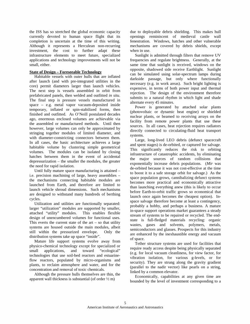
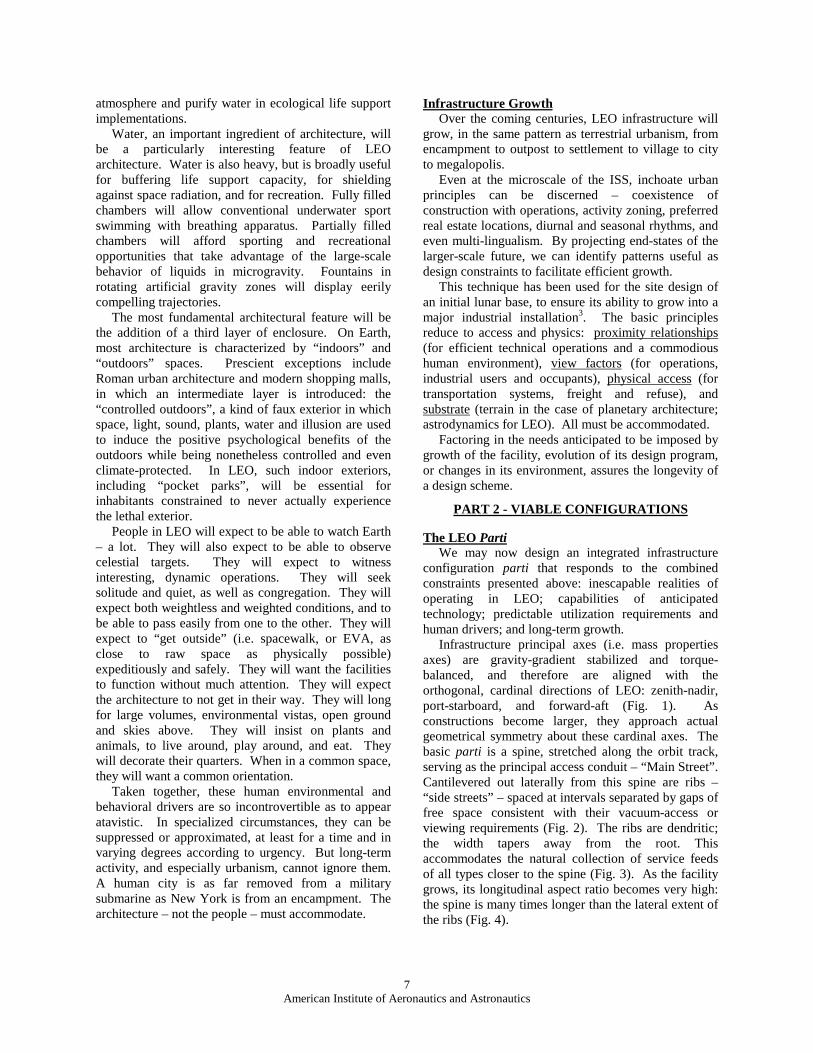
Infrastructure principal axes (i.e. mass properties axes) are gravity-gradient stabilized and torque-balanced, and therefore are aligned with the orthogonal, cardinal directions of LEO: zenith-nadir, port-starboard, and forward-aft (Fig. 1). As constructions become larger, they approach actual geometrical symmetry about these cardinal axes. The basic parti is a spine, stretched along the orbit track, serving as the principal access conduit – “Main Street”. Cantilevered out laterally from this spine are ribs –“side streets” – spaced at intervals separated by gaps of free space consistent with their vacuum-access or viewing requirements (Fig. 2). The ribs are dendritic; the width tapers away from the root. This accommodates the natural collection of service feeds of all types closer to the spine (Fig. 3). As the facility grows, its longitudinal aspect ratio becomes very high: the spine is many times longer than the lateral extent of the ribs (Fig. 4).
8American Institute of Aeronautics and Astronautics
Fig. 1. Infrastructure principal axes align with LEO cardinal directions
Fig. 2. Spine-and-rib parti enables growth
Fig. 3. Utility trunks bundle near the spine
Fig. 4. Aspect ratio matures with growth
Closest to the spine are functions requiring the greatest concentration of utilities services (e.g. environmental control equipment, laboratories, manufacturing), and uses supported by the greatest human traffic (e.g. public gatherings, retail, work-places). More naturally remote functions are deployed farther out in the ribs. Internal traffic is conveyed through a continuous pressurized tunnel along the spine. Early constructions use concatenated modules for this tunnel; the mature construction technique uses in situ extrusion assembly analogous to subterranean tunnel construction. Conveyance in the large-scale implementation is carried in redundant, adjacent tunnels, mechanically assisted on rails by linear
induction motors. Exterior conveyance is via rails along the ridge of the spine, with redundant external mechanical systems distributed along each side of, and accessible from, the rail corridor. The belly of the spine is open for Earth views as noted below (Fig. 5).
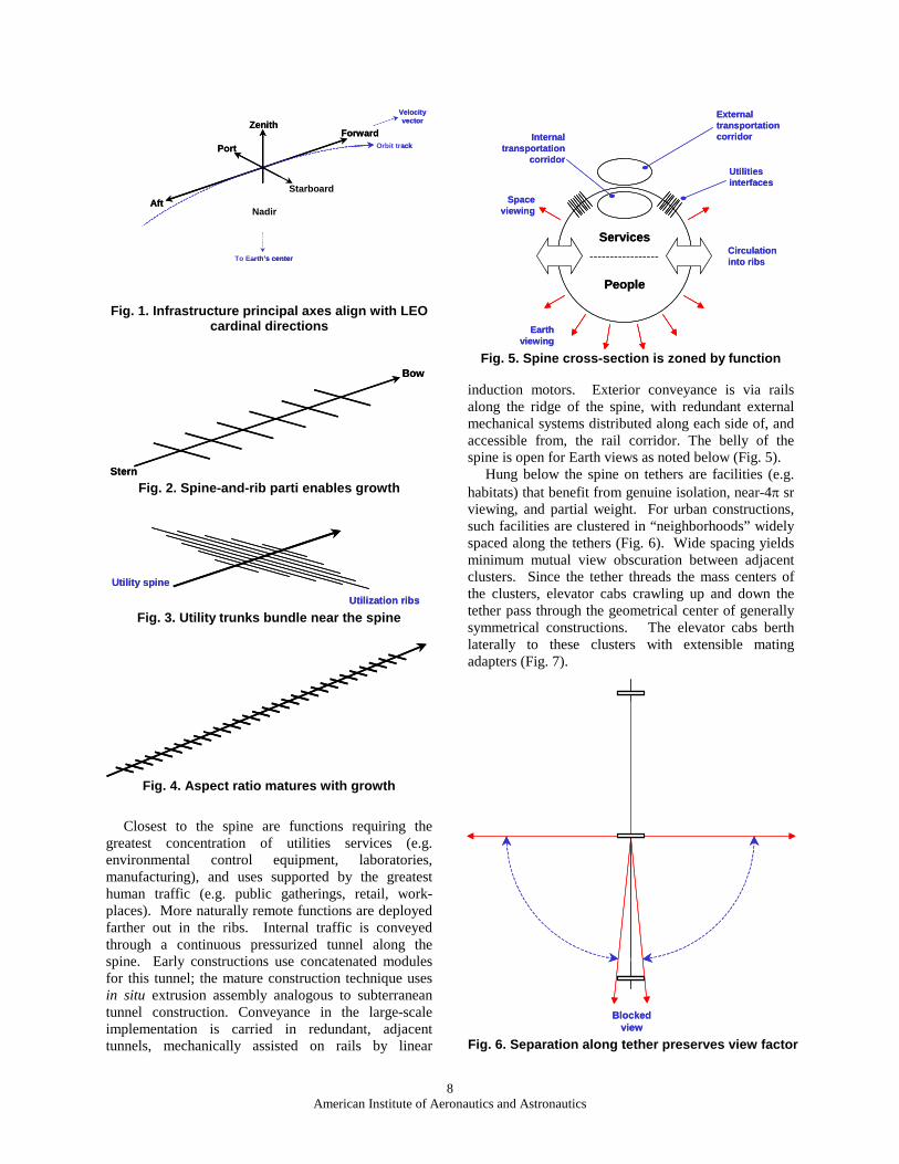
Hung below the spine on tethers are facilities (e.g. habitats) that benefit from genuine isolation, near-4π sr viewing, and partial weight. For urban constructions, such facilities are clustered in “neighborhoods” widely spaced along the tethers (Fig. 6). Wide spacing yields minimum mutual view obscuration between adjacent clusters. Since the tether threads the mass centers of the clusters, elevator cabs crawling up and down the tether pass through the geometrical center of generally symmetrical constructions. The elevator cabs berth laterally to these clusters with extensible mating adapters (Fig. 7).
Fig. 6. Separation along tether preserves view factor
Fig. 5. Spine cross-section is zoned by function
Nadir
Port
Starboard
Aft
Forward
To Earth’s center
ZenithVelocity vector
Orbit track
Nadir
Port
Starboard
Aft
Forward
To Earth’s center
ZenithVelocity vector
Orbit track
Bow
Stern
Bow
Stern
Utilization ribs
Utility spine
Utilization ribs
Utility spine
Circulation into ribs
People
Services
External transportation corridor
Utilities interfaces
Space viewing
Earth viewing
Internal transportation
corridor
Circulation into ribs
People
Services
External transportation corridor
Utilities interfaces
Space viewing
Earth viewing
Internal transportation
corridor
Blocked view
Blocked view
9American Institute of Aeronautics and Astronautics
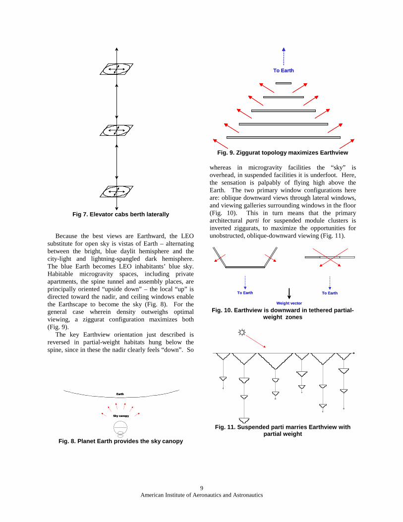
Because the best views are Earthward, the LEO substitute for open sky is vistas of Earth – alternating between the bright, blue daylit hemisphere and the city-light and lightning-spangled dark hemisphere. The blue Earth becomes LEO inhabitants’ blue sky. Habitable microgravity spaces, including private apartments, the spine tunnel and assembly places, are principally oriented “upside down” – the local “up” is directed toward the nadir, and ceiling windows enable the Earthscape to become the sky (Fig. 8). For the general case wherein density outweighs optimal viewing, a ziggurat configuration maximizes both (Fig. 9).
The key Earthview orientation just described is reversed in partial-weight habitats hung below the spine, since in these the nadir clearly feels “down”. So
Fig. 8. Planet Earth provides the sky canopy
Fig. 9. Ziggurat topology maximizes Earthview
whereas in microgravity facilities the “sky” is overhead, in suspended facilities it is underfoot. Here, the sensation is palpably of flying high above the Earth. The two primary window configurations here are: oblique downward views through lateral windows, and viewing galleries surrounding windows in the floor (Fig. 10). This in turn means that the primary architectural parti for suspended module clusters is inverted ziggurats, to maximize the opportunities for unobstructed, oblique-downward viewing (Fig. 11).
Fig. 10. Earthview is downward in tethered partial-weight zones
Fig. 11. Suspended parti marries Earthview with partial weight
Fig 7. Elevator cabs berth laterally
Earth
Sky canopy
Earth
Sky canopy
To EarthTo Earth
To Earth To Earth
Weight vector
To Earth To Earth
Weight vector
10American Institute of Aeronautics and Astronautics
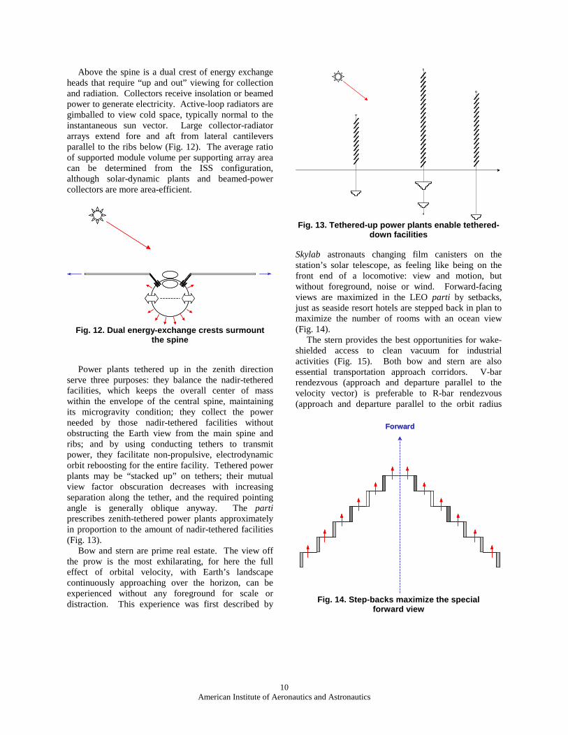
Above the spine is a dual crest of energy exchange heads that require “up and out” viewing for collection and radiation. Collectors receive insolation or beamed power to generate electricity. Active-loop radiators are gimballed to view cold space, typically normal to the instantaneous sun vector. Large collector-radiator arrays extend fore and aft from lateral cantilevers parallel to the ribs below (Fig. 12). The average ratio of supported module volume per supporting array area can be determined from the ISS configuration, although solar-dynamic plants and beamed-power collectors are more area-efficient.
Fig. 12. Dual energy-exchange crests surmount the spine
Power plants tethered up in the zenith direction serve three purposes: they balance the nadir-tethered facilities, which keeps the overall center of mass within the envelope of the central spine, maintaining its microgravity condition; they collect the power needed by those nadir-tethered facilities without obstructing the Earth view from the main spine and ribs; and by using conducting tethers to transmit power, they facilitate non-propulsive, electrodynamic orbit reboosting for the entire facility. Tethered power plants may be “stacked up” on tethers; their mutual view factor obscuration decreases with increasing separation along the tether, and the required pointing angle is generally oblique anyway. The partiprescribes zenith-tethered power plants approximately in proportion to the amount of nadir-tethered facilities (Fig. 13).
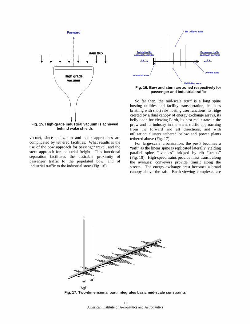
Bow and stern are prime real estate. The view off the prow is the most exhilarating, for here the full effect of orbital velocity, with Earth’s landscape continuously approaching over the horizon, can be experienced without any foreground for scale or distraction. This experience was first described by
Skylab astronauts changing film canisters on the station’s solar telescope, as feeling like being on the front end of a locomotive: view and motion, but without foreground, noise or wind. Forward-facing views are maximized in the LEO parti by setbacks, just as seaside resort hotels are stepped back in plan to maximize the number of rooms with an ocean view (Fig. 14).
The stern provides the best opportunities for wake-shielded access to clean vacuum for industrial activities (Fig. 15). Both bow and stern are also essential transportation approach corridors. V-bar rendezvous (approach and departure parallel to the velocity vector) is preferable to R-bar rendezvous (approach and departure parallel to the orbit radius
Fig. 14. Step-backs maximize the special forward view
Fig. 13. Tethered-up power plants enable tethered-down facilities
ForwardForward
11American Institute of Aeronautics and Astronautics
Fig. 15. High-grade industrial vacuum is achieved behind wake shields
vector), since the zenith and nadir approaches are complicated by tethered facilities. What results is the use of the bow approach for passenger travel, and the stern approach for industrial freight. This functional separation facilitates the desirable proximity of passenger traffic to the populated bow, and of industrial traffic to the industrial stern (Fig. 16).
Fig. 16. Bow and stern are zoned respectively for passenger and industrial traffic
So far then, the mid-scale parti is a long spine hosting utilities and facility transportation, its sides bristling with short ribs hosting user functions, its ridge crested by a dual canopy of energy exchange arrays, its belly open for viewing Earth, its best real estate in the prow and its industry in the stern, traffic approaching from the forward and aft directions, and with utilization clusters tethered below and power plants tethered above (Fig. 17).
For large-scale urbanization, the parti becomes a “raft” as the linear spine is replicated laterally, yielding parallel spine “avenues” bridged by rib “streets” (Fig. 18). High-speed trains provide mass transit along the avenues; conveyors provide transit along the streets. The energy-exchange crest becomes a broad canopy above the raft. Earth-viewing complexes are
Fig. 17. Two-dimensional parti integrates basic mid-scale constraints
Forward
Ram flux
High grade vacuum
Forward
Ram flux
High grade vacuum
Freight trafficapproach corridor
± v± v
Passenger trafficapproach corridor
Habitation zone
EM utilities zone
Industrial zoneLeisure zone
Freight trafficapproach corridor
± v± v± v± v
Passenger trafficapproach corridor
Habitation zone
EM utilities zone
Industrial zoneLeisure zone
Freight traffic
Passenger traffic
Velocity vector
Freight traffic
Passenger traffic
Velocity vector
12American Institute of Aeronautics and Astronautics
Fig. 18. Spines multiply into avenues; ribs grow into cross streets
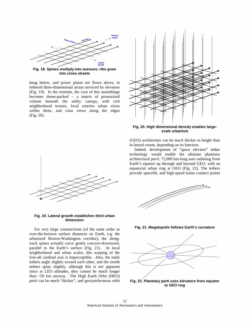
hung below, and power plants are flown above, in tethered three-dimensional arrays serviced by elevators (Fig. 19). In the extreme, the core of this assemblage becomes dense-packed – a matrix of pressurized volume beneath the utility canopy, with rich neighborhood texture, local exterior urban views within them, and vista views along the edges (Fig. 20).
For very large constructions (of the same order as over-the-horizon surface distances on Earth, e.g. the urbanized Boston-Washington corridor), the along-track spines actually curve gently concave-downward, parallel to the Earth’s surface (Fig. 21). At local neighborhood and urban scales, this warping of the fore-aft cardinal axis is imperceptible. Also, the nadir tethers angle slightly toward each other, and the zenith tethers splay slightly, although this is not apparentsince at LEO altitudes, they cannot be much longer than ~50 km anyway. The High Earth Orbit (HEO) parti can be much “thicker”, and geosynchronous orbit
Fig. 20. High dimensional density enables large-scale urbanism
(GEO) architecture can be much thicker in height than in lateral extent, depending on its function.
Indeed, development of “space elevator” tether technology would enable the ultimate planetary architectural parti: 72,000 km-long axes radiating from Earth’s equator up through and beyond GEO, with an equatorial urban ring at GEO (Fig. 22). The tethers provide spacelift, and high-speed trains connect points
Fig. 21. Megalopolis follows Earth’s curvature
Fig. 22. Planetary parti uses elevators from equator to GEO ring
Fig. 19. Lateral growth establishes third urban dimension
AvenuesCross streets
Velocity vector
Lateral growth
AvenuesCross streets
Velocity vector
Lateral growth
13American Institute of Aeronautics and Astronautics
along the ring. The GEO ring is built out laterally for growth, built down for Earth-looking uses (communications, imagery, recreation), and provides a way station for orbit transfer systems to other destinations. The extent of facility build-out at other altitudes is a function only of economic demand, tether material strength, and number of tethers used to hang them. Similarly, extensive cross-track build-out would enable non-equatorial spacelift tethers.
Artificial GravityApart from industrial needs, general mixed-use
LEO architecture includes microgravity, partial-weight and artificial-weight zones. Internal ballistic motions in rotating environments are counter-intuitive and therefore provide interesting opportunities for living, sport and art. However, 4π sr motions in microgravity environments, and the settling bias in partial-weight environments, provide equally interesting, yet very different, opportunities for living, working, sport and art.
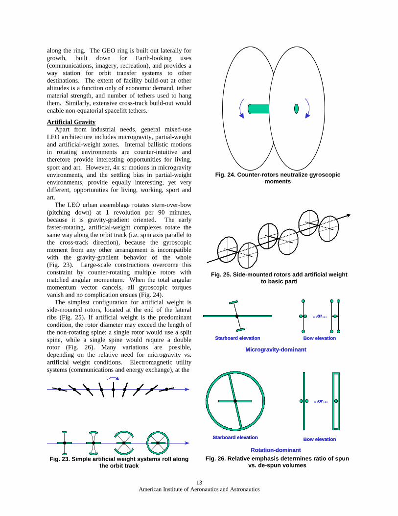
The LEO urban assemblage rotates stern-over-bow (pitching down) at 1 revolution per 90 minutes, because it is gravity-gradient oriented. The early faster-rotating, artificial-weight complexes rotate the same way along the orbit track (i.e. spin axis parallel to the cross-track direction), because the gyroscopic moment from any other arrangement is incompatible with the gravity-gradient behavior of the whole (Fig. 23). Large-scale constructions overcome this constraint by counter-rotating multiple rotors with matched angular momentum. When the total angular momentum vector cancels, all gyroscopic torques vanish and no complication ensues (Fig. 24).
The simplest configuration for artificial weight is side-mounted rotors, located at the end of the lateral ribs (Fig. 25). If artificial weight is the predominant condition, the rotor diameter may exceed the length of the non-rotating spine; a single rotor would use a split spine, while a single spine would require a double rotor (Fig. 26). Many variations are possible, depending on the relative need for microgravity vs. artificial weight conditions. Electromagnetic utility systems (communications and energy exchange), at the
Fig. 24. Counter-rotors neutralize gyroscopic moments
Fig. 23. Simple artificial weight systems roll along the orbit track
Fig. 25. Side-mounted rotors add artificial weight to basic parti
Fig. 26. Relative emphasis determines ratio of spun vs. de-spun volumes
Rotation-dominant
Microgravity-dominant
…or…
Starboard elevation Bow elevation
…or…
Starboard elevation Bow elevation
Rotation-dominant
Microgravity-dominant
…or……or…
Starboard elevation Bow elevation
…or…
Starboard elevation Bow elevation
…or……or…
Starboard elevation Bow elevation
14American Institute of Aeronautics and Astronautics
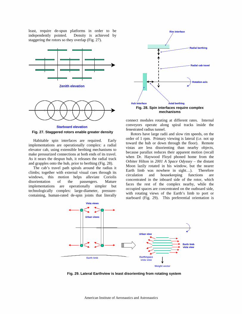
least, require de-spun platforms in order to be independently pointed. Density is achieved by staggering the rotors so they overlap (Fig. 27).
Habitable spin interfaces are required. Early implementations are operationally complex: a radial elevator cab, using extensible berthing mechanisms to make pressurized connections at both ends of its travel. As it nears the despun hub, it releases the radial track and grapples onto the hub, prior to berthing (Fig. 28).
The cab’s travel path spirals around the radius it climbs; together with external visual cues through its windows, this motion helps alleviate Coriolis disorientation of the passengers. Mature implementations are operationally simpler but technologically complex: large-diameter, pressure-containing, human-rated de-spin joints that literally
connect modules rotating at different rates. Internal conveyors operate along spiral tracks inside the fenestrated radius tunnel.
Rotors have large radii and slow rim speeds, on the order of 1 rpm. Primary viewing is lateral (i.e. not up toward the hub or down through the floor). Remote vistas are less disorienting than nearby objects, because parallax reduces their apparent motion (recall when Dr. Haywood Floyd phoned home from the Orbiter Hilton in 2001 A Space Odyssey – the distant Moon lazily rotated in his window, but the nearer Earth limb was nowhere in sight…). Therefore circulation and housekeeping functions are concentrated in the inboard side of the rotor, which faces the rest of the complex nearby, while the occupied spaces are concentrated on the outboard side, with rotating views of the Earth’s limb to port or starboard (Fig. 29). This preferential orientation is
Fig. 27. Staggered rotors enable greater density
Fig. 28. Spin interfaces require complex mechanisms
Earth limb
Vista views
Urban views
Weight vector
Earth limb vista view
Urban view
Earth/space vista view
Earth limb
Vista views
Urban views
Weight vector
Earth limb vista view
Urban view
Earth/space vista view
Starboard elevation
Zenith elevation
Starboard elevation
Zenith elevation
Fig. 29. Lateral Earthview is least disorienting from rotating system
Radial berthing
Axial berthingHub interface
Rim interface
Radial cab travel
Rotation axis
Radial berthing
Axial berthingHub interface
Rim interface
Radial cab travel
Rotation axis
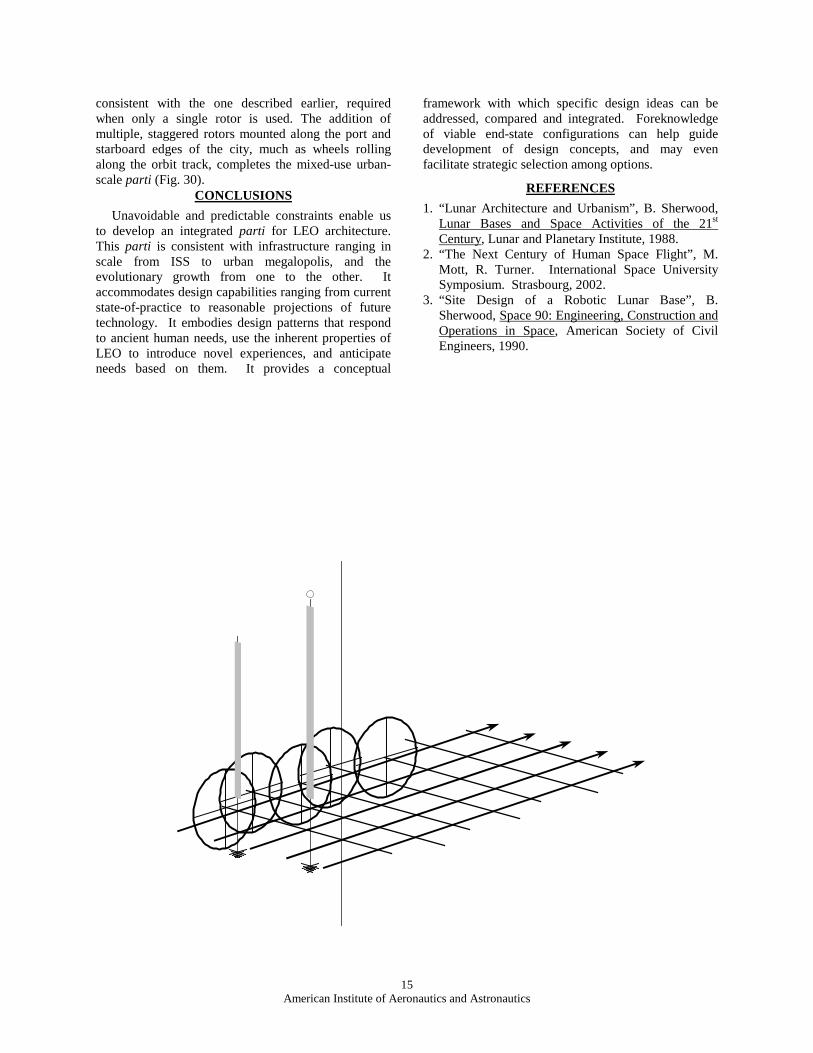
15American Institute of Aeronautics and Astronautics
consistent with the one described earlier, required when only a single rotor is used. The addition of multiple, staggered rotors mounted along the port and starboard edges of the city, much as wheels rolling along the orbit track, completes the mixed-use urban-scale parti (Fig. 30).
CONCLUSIONS
Unavoidable and predictable constraints enable us to develop an integrated parti for LEO architecture. This parti is consistent with infrastructure ranging in scale from ISS to urban megalopolis, and the evolutionary growth from one to the other. It accommodates design capabilities ranging from current state-of-practice to reasonable projections of future technology. It embodies design patterns that respond to ancient human needs, use the inherent properties of LEO to introduce novel experiences, and anticipate needs based on them. It provides a conceptual
framework with which specific design ideas can be addressed, compared and integrated. Foreknowledge of viable end-state configurations can help guide development of design concepts, and may even facilitate strategic selection among options.
REFERENCES
1. “Lunar Architecture and Urbanism”, B. Sherwood, Lunar Bases and Space Activities of the 21st
Century, Lunar and Planetary Institute, 1988.2. “The Next Century of Human Space Flight”, M.
Mott, R. Turner. International Space University Symposium. Strasbourg, 2002.
3. “Site Design of a Robotic Lunar Base”, B. Sherwood, Space 90: Engineering, Construction and Operations in Space, American Society of Civil Engineers, 1990.
Fig. 30. Three-dimensional urban parti integrates basic large-scale constraints