Design Optimization of a Customized Dental Implant ...
10
Design Optimization of a Customized Dental Implant Manufactured via Electron Beam Melting ® Gilbert Chahine 1 , Hosein Atharifar 2 , Pauline Smith 3 and Radovan Kovacevic 1 1: Research Center for Advanced Manufacturing (RCAM), Department of Mechanical Engineering, Southern Methodist University, Dallas Texas 7520 2: Department of Industry and Technology, Millersville University, Millersville Pennsylvania 17551 3: Army Research Laboratory, Aberdeen Proving Ground, MD 21005 Finite Element Analysis (FEA) is a commonly used tool to evaluate biomechanics of traditional dental implants. Biomechanics help predict bone response and implant retention which strongly affects the longevity of the implant. The current research utilizes an analogues approach with FEA, to evaluate the biomechanics of a customized dental implant design built by Electron Beam Melting®, and to contribute towards the implant’s design optimization. The analysis consists of three distinct simulation models. The first model is established in order to get an insight of the biomechanics produced by a biting force of 400 N on a second human molar in the mandible, its corresponding superposed mate and the surrounding biomaterial. In the second model, the lower jaw molar is replaced by a Ti-6Al-4V customized dental implant with a solid surface at the root. In the third model, the customized dental implant has a modified outer-layer at the root with adjustable elasticity. By using a deterministic optimization technique in the FEA, an elasticity of the modified layer can be selected in a manner to minimize stress shielding from occurring. Introduction: In modern dental Implantology, dental implants are composed of three components; a screw-like root form inserted into a drilled and bored hole in the jawbone, an abutment which provides support for a dental prosthesis, and a screw which connects these components [1]. Previous work discusses the new concept of a one-component customized dental implant which mimics the shape of the natural tooth and makes use of the socket produced by extraction [2]. The new concept potentially evades the need for drilling and boring used in traditional implantation, which consequently decreases mechanical and thermal trauma; hence, inducing faster healing time [2]. The literature discusses a case study, where a CT scan is obtained from a patient, and is used to design a customized dental implant. The design is manufactured using an EBM® A 2 ARCAM® machine out of Ti-6Al-4V ELI. The biomechanics of dental implants are essential to bone response, implant longevity and stability. Consequently, it is important to compare the biomechanics produced by the use of customized dental implants to the biomechanics present in natural dentitions. Finite Element Analysis (FEA) is a cost- effective and insightful tool used in predicting mechanical and thermal behavior of traditional dental implants in their bio-environment. Such analysis enables researchers to obtain information regarding the nature of the biting load, and the induced stress and strain into the dental implant and the surrounding bone [3]. With the numerous benefits that FEA provides, similar analysis is used to evaluate the biomechanics of customized dental implants, and provide a gateway to optimize the mechanical features of their design. International Solid Freeform Fabrication Symposium Aug 3-5, 2009, Austin Texas
Transcript of Design Optimization of a Customized Dental Implant ...

Design Optimization of a Customized Dental Implant
Manufactured via Electron Beam Melting®
Gilbert Chahine1, Hosein Atharifar2, Pauline Smith3 and Radovan Kovacevic1
1: Research Center for Advanced Manufacturing (RCAM), Department of Mechanical Engineering, Southern Methodist University, Dallas Texas 7520 2: Department of Industry and Technology, Millersville University, Millersville Pennsylvania 17551 3: Army Research Laboratory, Aberdeen Proving Ground, MD 21005
Finite Element Analysis (FEA) is a commonly used tool to evaluate biomechanics of traditional dental implants. Biomechanics help predict bone response and implant retention which strongly affects the longevity of the implant. The current research utilizes an analogues approach with FEA, to evaluate the biomechanics of a
customized dental implant design built by Electron Beam Melting®, and to contribute towards the implant’s design optimization. The analysis consists of three distinct simulation models. The first model is established in order to get an insight of the biomechanics produced by a biting force of 400 N on a second human molar in the mandible, its corresponding superposed mate and the surrounding biomaterial. In the second model, the lower jaw molar is replaced by a Ti-6Al-4V customized dental implant with a solid surface at the root. In the third model, the customized dental implant has a modified outer-layer at the root with adjustable elasticity. By using a deterministic optimization technique in the FEA, an elasticity of the modified layer can be selected in a manner to minimize stress shielding from occurring.
Introduction: In modern dental Implantology, dental implants are composed of three components; a screw-like root
form inserted into a drilled and bored hole in the jawbone, an abutment which provides support for a
dental prosthesis, and a screw which connects these components [1].
Previous work discusses the new concept of a one-component customized dental implant which mimics
the shape of the natural tooth and makes use of the socket produced by extraction [2]. The new concept
potentially evades the need for drilling and boring used in traditional implantation, which consequently
decreases mechanical and thermal trauma; hence, inducing faster healing time [2]. The literature
discusses a case study, where a CT scan is obtained from a patient, and is used to design a customized
dental implant. The design is manufactured using an EBM® A2 ARCAM® machine out of Ti-6Al-4V ELI.
The biomechanics of dental implants are essential to bone response, implant longevity and stability.
Consequently, it is important to compare the biomechanics produced by the use of customized dental
implants to the biomechanics present in natural dentitions. Finite Element Analysis (FEA) is a cost-
effective and insightful tool used in predicting mechanical and thermal behavior of traditional dental
implants in their bio-environment. Such analysis enables researchers to obtain information regarding
the nature of the biting load, and the induced stress and strain into the dental implant and the
surrounding bone [3]. With the numerous benefits that FEA provides, similar analysis is used to evaluate
the biomechanics of customized dental implants, and provide a gateway to optimize the mechanical
features of their design.
International Solid Freeform Fabrication Symposium
Aug 3-5, 2009, Austin Texas
rosalief
Typewritten Text
631
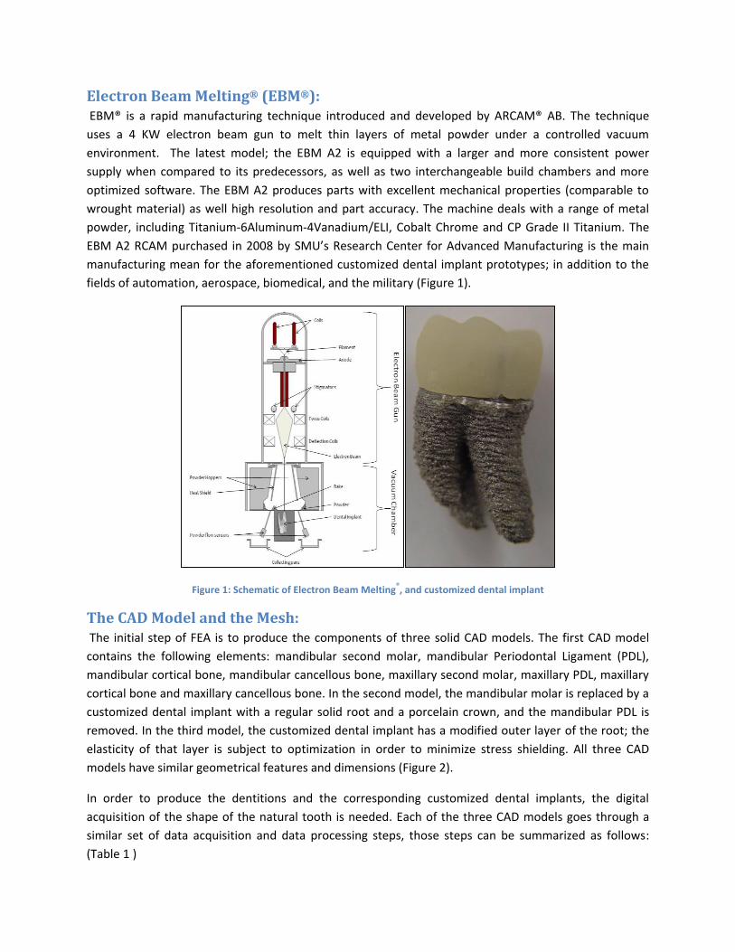
Electron Beam Melting® (EBM®): EBM® is a rapid manufacturing technique introduced and developed by ARCAM® AB. The technique
uses a 4 KW electron beam gun to melt thin layers of metal powder under a controlled vacuum
environment. The latest model; the EBM A2 is equipped with a larger and more consistent power
supply when compared to its predecessors, as well as two interchangeable build chambers and more
optimized software. The EBM A2 produces parts with excellent mechanical properties (comparable to
wrought material) as well high resolution and part accuracy. The machine deals with a range of metal
powder, including Titanium-6Aluminum-4Vanadium/ELI, Cobalt Chrome and CP Grade II Titanium. The
EBM A2 RCAM purchased in 2008 by SMU’s Research Center for Advanced Manufacturing is the main
manufacturing mean for the aforementioned customized dental implant prototypes; in addition to the
fields of automation, aerospace, biomedical, and the military (Figure 1).
Figure 1: Schematic of Electron Beam Melting®, and customized dental implant
The CAD Model and the Mesh: The initial step of FEA is to produce the components of three solid CAD models. The first CAD model
contains the following elements: mandibular second molar, mandibular Periodontal Ligament (PDL),
mandibular cortical bone, mandibular cancellous bone, maxillary second molar, maxillary PDL, maxillary
cortical bone and maxillary cancellous bone. In the second model, the mandibular molar is replaced by a
customized dental implant with a regular solid root and a porcelain crown, and the mandibular PDL is
removed. In the third model, the customized dental implant has a modified outer layer of the root; the
elasticity of that layer is subject to optimization in order to minimize stress shielding. All three CAD
models have similar geometrical features and dimensions (Figure 2).
In order to produce the dentitions and the corresponding customized dental implants, the digital
acquisition of the shape of the natural tooth is needed. Each of the three CAD models goes through a
similar set of data acquisition and data processing steps, those steps can be summarized as follows:
(Table 1 )
rosalief
Typewritten Text
632

A CT scan of an anonymous patient, composed of 200 images interspaced by 0.1 mm is obtained. The
scan covers the mandible area which displays a second molar. The CT scan imported into Mimics of
Materialise®, is processed to
produce a 3D model of the
second molar exported as a
.stl (Standard Triangulation
Language) file. The .stl file is
imported into Magics of
Materialise® where .stl fixing
module is employed to
produce a water tight model.
Next, Geomagic® Studio
V.11.0 is used to produce
manifolds and surface
patches in order to generate a solid model of the molar, which is exported as an .iges (Initial Graphics
Exchange Specification) format. And finally Autodesk® Inventor® 2010 is used to produce two implant
designs, and the rest of the bio-components corresponding to the three CAD models.
Figure 2: Schematic of the three models of the FEA
A 3D representation of the first model and its corresponding mesh is shown in Figure 3. The mesh
control is embedded in ANSYS® 11.0 Workbench® software, which has a useful defeaturing algorithm
that enables the program to ignore sliver areas, hence producing a robust mesh and avoiding the need
for CAD cleanup.
ANSYS 11.0 Workbench 11.0
Autodesk Inventor 2010
Geomagic Studio V.11.0
Magics V.12.0 Materialise
Mimics V.12 Materialise
CT scan of a second molar in the mandible
Table 1: Method for obtaining the CAD Model
rosalief
Typewritten Text
633

Figure 3: Schematic of the CAD model, its corresponding mesh, and an excerpt of the two dentitions and the PDL
Material Properties: All materials are assumed to be isotropic and linear elastic. Table 2 displays a list of the materials, their
corresponding mechanical properties and references.
Table 2: List of Materials and the corresponding mechanical properties
Young’s Modulus (MPa)
Poisson’s Ratio Reference
Human tooth 20 000 0.30 Abé et al (1996) [4] Periodontal ligament (human molar)
350 0.45 Atmaran and Mohammed (1981) [5]
Cortical human jaw bone
20 000 0.3 Abé et al (1996) [4]
Cancellous human jaw bone
3000 0.31 Abé et al (1996) [4]
Ti-6Al-4V 110 000 0.33 Colling (1984) [6] Porcelain 68900 0.28 Lewinstein (1995) [7]
The elasticity of the modified outer-layer of the root in the third model is adjusted using an optimizing
scheme called design modeling in ANSYS® 11.0 Workbench® . As a preliminary step an initial Young’s
Modulus of 10 000 MPa and a Poisson’s Ratio of 0.33 has been selected.
rosalief
Typewritten Text
634

Boundary Conditions and Loads:
A static analysis of the three models us executed, where a static load is applied,
and static entities such stress, strain and deformation are evaluated.
ANSYS® Workbench® has the ability to detect contact regions. The three models
have respectively 7, 8 and 9 contact regions. In this simulation, the nature of
contact is selected to be bonded.
A human bite load is in the range of 200 N to 500 N [8]. A pressure corresponding
to a load of 400 N is applied on the top surface of the cortical bone of the maxilla
and fixed support is applied on the bottom surface of the cortical bone of the
mandible (Figure 4).
Discussion of the Results of the first two models: The time needed to solve the three models was in the order of a few minutes. The very short lead time
of obtaining results using FEA is one of the main advantages of technique as well as cost-effectiveness,
especially compared to lengthy and costly in vitro and in vivo experiments.
Examining the results of the first model (Figure 5), a maximum deformation of 23.5 microns is observed
at the bottom area of the cancellous and cortical bone. This value of deformation is under the
destructive value of 150 microns [10]. The deformation within the natural tooth is in the range of 7 to 13
microns. A few probes are positioned in the cancellous bone close the PDL, and corresponding probes
are selected across the PDL within the dentition. The stress range of the probes in the cancellous bone is
between 1.3 to 3.6 MPa, which matches the stress range of 1.4 to 5 MPa suggested by Rieger et al. [9]
for optimal bone health.
Figure 5: Plot of the total deformation (a), and the equivalent stress in the first model (b)
Figure 4: Boundary Conditions and Loads of the 1st model
a) b)
rosalief
Typewritten Text
635
The stress range of the probes selected within the tooth is 2 to 6.8 MPa. The stress in the tooth is
slightly higher than the stress in the surrounding cancellous bone. This difference of stress ranges is an
important indication of the occurrence of stress shielding. The PDL in the first model is considered a
linearly elastic material, which is a simplification compared to the commonly known hyper-elastic and
visco-elactic portrait of the material [11].
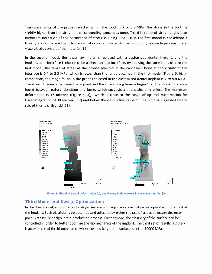
In the second model, the lower jaw molar is replaced with a customized dental Implant, and the
implant/bone interface is chosen to be a direct contact interface. By applying the same loads used in the
first model, the range of stress at the probes selected in the cancellous bone at the vicinity of the
interface is 0.4 to 2.5 MPa, which is lower than the range obtained in the first model (Figure 5, b). In
comparison, the range found in the probes selected in the customized dental implant is 2 to 9.4 MPa .
The stress difference between the implant and the surrounding bone is larger than the stress difference
found between natural dentition and bone, which suggests a stress shielding effect. The maximum
deformation is 17 microns (Figure 5, a), which is close to the range of optimal micromotion for
Osseointegration of 30 microns [12] and below the destructive value of 100 microns suggested by the
rule of thumb of Brunski [13].
Figure 6: Plot of the total deformation (a), and the equivalent stress in the second model (b)
Third Model and Design Optimization: In the third model, a modified outer-layer surface with adjustable elasticity is incorporated to the root of
the implant. Such elasticity is be obtained and adjusted by either the use of lattice structure design or
porous structure design in the production process. Furthermore, the elasticity of the surface can be
controlled in order to better optimize the biomechanics of the implant. The third set of results (Figure 7)
is an example of the biomechanics when the elasticity of the surface is set to 10000 MPa.
a) b)
rosalief
Typewritten Text
636

Figure 7: A plot of the total deformation (a), and the equivalent stress in the third model (b)
It is noticeable that the stress shielding is reduced, and the micromotion is slightly increased, which
implies that controlling the elasticity of the outer-surface does indeed affect the deformation, and the
load transfer when compared to the second model (where the modified outer-layer is non-existent).
These findings led to the use of an optimization module called DesignXplorer in ANSYS® 11.0
Workbench®, which uses a deterministic method of changing design variables to find an optimal
outcome. Central Composite Design (CCD) is the underlying Design of Experiment technique selected to
obtain higher accuracy in the experimental design.
Figure 8, Schematic of the locations of the 15 probes inserted into the third model
Referring to Figure 8, five probing areas are selected on a transversal cross section. Every area contains
three stress probing positions; on the cancellous bone, the modified outer-layer and the implant solid
core. Computing the variance of the values of stresses in each group of three probes provides a
qualitative estimate of the stress shielding at that location. The greater the variance of stresses, the
larger the stress shielding, and vice versa. Variance is the measure of the average deviation of the
elements of a population from their mean values. The square variance of a population is defined
by: 𝜎2 = (𝑥𝑘−𝜇 )2𝑛𝑘=1
𝑛, where n is the number of elements, xk the element with index k, and µ the mean
value.
a) b)
rosalief
Typewritten Text
637

The input parameters are selected to be the biting pressure applied on the model and the elasticity of
the interface. The parameters’ corresponding ranges are 0.25 to 2 MPa and 5 000 to 200 000 MPa
respectively.
Table 3, Optimal Elasticity at the five probing areas
Probe Area 1 2 3 4 5
Optimal Elasticity (GPa)
100 130 110 120 84
Figure 8Figure 9 (1-5) displays 3D plots of the variance versus the pressure applied, and the elasticity of
the layer. As the pressure applied increases the variance increases. While in the range of elasticity, a
local minimum value of variance can be detected at every single probe area. Table 3 provides a
summary of the optimal elasticity found for different probe areas. An optimal elasticity corresponds to a
minimum variance, hence minimum stress shielding.
This final finding is applicable to the ability of prototyping technique based on Electron Beam Melting®
to produce parts with high geometric complexity and locally tailored mechanical properties. By finding
the desired elasticity at different areas in the implant, the design of the porous structures is reciprocally
optimized and manufactured in order to provide the desired elasticity.
Figure 9 (6) displays the aggregate variance of the five probing areas. From a global perspective, it is still
very eminent that an optimal elasticity is evaluated based on the minimal variance of stresses, hence
minimal stress shielding.
1) 2)
3) 4)
rosalief
Typewritten Text
638

5) 6)
Figure 9: Plots of the Stress variance at the 5 corresponding probing areas, versus the selected ranges of pressure and interface elasticity (1-5), Plot of the aggregate variance of the five probing areas (6)
Conclusion: In conclusion, FEA provided numerous improvements by optimizing the design through the evaluation of
the biomechanics of natural dentition and customized dental implants. The model displayed in the
current research serves as a foundation for more complicated models which aim towards a more
sophisticated representation of the implant/bone interface and the PDL, which provides more accurate
and more realistic results.
Furthermore, the current exhibits the benefit of rapid manufacturing in providing prominent design
flexibility, which is embodied by the concept of customized dental implants and the various geometrical
and mechanical modifications it offers in comparison to traditional standardized dental implants. These
modifications contribute to faster healing time, better implant retention and enhanced patient comfort
and satisfaction.
Acknowledgement: The US Army Research Office granted SMU a grant to develop a program entitled: “Advanced Precision
Supply Parts Manufacturing”, Grant No. W911NF-07-2-0056. In October 2007, in corporation with the
Army Research Laboratory, SMU acquired the ARCAM A2 machine, for solid freeform fabrication by
electron beam in a vacuum environment manufactured by ARCAM AB, Gothenburg, Sweden.
rosalief
Typewritten Text
639

References: [1]Misch, E. C., (1999), Contemporary Implant Dentistry, Mosby
[2]Chahine G., Koike M., Okabe T., Smith P., and Kovacevic R., “The Design and Production of Ti-6Al-4V ELI Customized Dental
Implants”, JOM, Volume 60, Issue 11, pp.50-55
[3] Watanabe, F., Hata, Y., Komatsu, S., Ramos, T.C., and Fukuda, H., 2003, Finite element analysis of the influence of implant
inclination, loading position, and load direction on stress distribution. Odontology, 9(1), 31-36
[4] F. Abe et al., Phys. Rev. Lett. 77, 438 (1996)
[5] Atmaram GH, Mohammed H (1981) Estimation of physiologic stresses with a nature tooth considering fibrous PDL structure.
J Dent Res 60:873-877
[6] Colling EW (1984) The Physical Metallurgy of Titanium Alloys. Metal Park, Ohio: American Society of Metals
[7] Lewinstein I, Banks-Sills L, Eliasi R (1995) Finite element analysis of a new system (IL) for supporting implant-retained
cantilever prosthesis. J Prosthet Dent 10:355-366
[8]ASTM F 67-95: Standard specification for unalloyed titanium for surgical implant application, American Society for testing
and materials, Philadelphia, 1995
[9] Rieger MR, Mayberry M, Brose MO (1990) Finite element analysis of six endosseous implants. J Prosthet Dent 63:671-676
[10] Soballe, k.; Hansen, E. S.; Brockstedt-Rasmussen, H.; Bunger, C. The effects of osteoporosis, bone deficiency, bone grafting
and micromotion on fixation of porous-coated hydroxyapatite-coated implants. Geesink, R. G. T.; Manley, M. T., Eds.
Hydroxyapatite Coatings in Orthopaedic Surgery, New York: Raven Press; 1993:107-136
[11]Natali, A. (Ed.), Dental Biomechanics, Taylor & Francis, New York, NY, 10001
[12] Pilliar, R. M. Quantitative evaluation of the effect of movement at a porous coated implant-bone interface. Davies, E. J., Ed.
The Bone-Biomaterial Interface. Toronto: University of Toronto Press; 1991:380-387.
[13] Brunski, J. B. Avoid pitfalls of overloading and micromotion of intraosseous implants. Dent. Implantol. Update 4:1-5;1993
rosalief
Typewritten Text
640