Design optimization of a B-pillar for crashworthiness of ...
18
Journal of Mechanical Engineering and Sciences ISSN (Print): 2289-4659; e-ISSN: 2231-8380 Volume 11, Issue 2, pp. 2693-2710, June 2017 © Universiti Malaysia Pahang, Malaysia DOI: https://doi.org/10.15282/jmes.11.2.2017.11.0245 2693 Design optimization of a B-pillar for crashworthiness of vehicle side impact A. E. Ikpe 1* , I. B. Owunna and P. Satope Department of Mechanical Engineering, Coventry University, West Midlands, UK * E-mail: [email protected] Phone: +2348125434634 or +447586821646 ABSTRACT In this study, Hypermesh and Catia V5 software were adopted for finite element analysis (FEA) of a vehicle B-pillar. The design objectives were to optimise the B-Pillar such that the maximum displacement, weight, and maximum stress value of B-Pillar is minimised without compromising its yield strength and impact resistant properties. This is significant for the improvement of a vehicle’s crashworthiness and ensuring the safety of passenger(s) during road accidents. This study initially analysed a given B-pillar design after being subjected to an even force of 140kN. The result produced von Mises stress of 1646MPa and deflection of 5.9mm. To ensure that EuroCAP directives were met, the B- Pillar was reinforced by adding extra steel plates to its inner surface and applying seam welding to ascertain their fusion and analysed using the same force of 140kN. Analysis of the reinforced B-Pillar design produced maximum von Mises stress of 673MPa with a maximum displacement value of 2.39mm. The optimised B-Pillar design was reinforced with 1.7kg steel plate with the overall mass of the B-Pillar amounting to 4.2kg of the total design compared to the original B-Pillar which had a total mass of 6kg. The optimised B- Pillar possessed less weight beside capable of resisting a force of 140kN with von Mises stress and displacement rate lower than the original B-Pillar. Thus, this indicates improvement in the tensile strength, stiffness, and impact resistant behaviour against collision forces by acting sideward on vehicles during road accidents. This can save such vehicles and passengers from severe damage that may result in loss of lives and properties. Hence, B-Pillar must be designed following the existing standards and tested before installation on vehicles to avoid unforeseen catastrophes. Keywords: B-pillar, design; crashworthiness; side impact; vehicle, safety. INTRODUCTION Structural optimisation is very important in engineering designs. It is an important tool used to remove unnecessary features and improve the function of a component or system. The main objective of this study is to analyse the structural capacity of a B-Pillar design used in automobiles. The result will be an optimised model that meets EuroCAP directives. The B-pillar is an essential load-carrying element in any automobile framework. It functions as a primary supporting structure for the roof. It is characterised by a thin-walled, seam-welded, closed-sectioned structure made from high strength steels [1-3]. B-pillar is the most forward pillar on each side of a vehicle that is in whole or part, rearward of a transverse vertical plane passing through the seating reference point of the driver’s seat[4]. B-Pillar is the pillar presents on both sides of a given vehicle between the rear and front doors. The B-Pillar mounted on a vehicle for latching of the front doors
Transcript of Design optimization of a B-pillar for crashworthiness of ...

Journal of Mechanical Engineering and Sciences
ISSN (Print): 2289-4659; e-ISSN: 2231-8380
Volume 11, Issue 2, pp. 2693-2710, June 2017
© Universiti Malaysia Pahang, Malaysia
DOI: https://doi.org/10.15282/jmes.11.2.2017.11.0245
2693
Design optimization of a B-pillar for crashworthiness of vehicle side impact
A. E. Ikpe1*, I. B. Owunna and P. Satope
Department of Mechanical Engineering, Coventry University, West Midlands, UK *E-mail: [email protected]
Phone: +2348125434634 or +447586821646
ABSTRACT
In this study, Hypermesh and Catia V5 software were adopted for finite element analysis
(FEA) of a vehicle B-pillar. The design objectives were to optimise the B-Pillar such that
the maximum displacement, weight, and maximum stress value of B-Pillar is minimised
without compromising its yield strength and impact resistant properties. This is
significant for the improvement of a vehicle’s crashworthiness and ensuring the safety of
passenger(s) during road accidents. This study initially analysed a given B-pillar design
after being subjected to an even force of 140kN. The result produced von Mises stress of
1646MPa and deflection of 5.9mm. To ensure that EuroCAP directives were met, the B-
Pillar was reinforced by adding extra steel plates to its inner surface and applying seam
welding to ascertain their fusion and analysed using the same force of 140kN. Analysis
of the reinforced B-Pillar design produced maximum von Mises stress of 673MPa with a
maximum displacement value of 2.39mm. The optimised B-Pillar design was reinforced
with 1.7kg steel plate with the overall mass of the B-Pillar amounting to 4.2kg of the total
design compared to the original B-Pillar which had a total mass of 6kg. The optimised B-
Pillar possessed less weight beside capable of resisting a force of 140kN with von Mises
stress and displacement rate lower than the original B-Pillar. Thus, this indicates
improvement in the tensile strength, stiffness, and impact resistant behaviour against
collision forces by acting sideward on vehicles during road accidents. This can save such
vehicles and passengers from severe damage that may result in loss of lives and
properties. Hence, B-Pillar must be designed following the existing standards and tested
before installation on vehicles to avoid unforeseen catastrophes.
Keywords: B-pillar, design; crashworthiness; side impact; vehicle, safety.
INTRODUCTION
Structural optimisation is very important in engineering designs. It is an important tool
used to remove unnecessary features and improve the function of a component or system.
The main objective of this study is to analyse the structural capacity of a B-Pillar design
used in automobiles. The result will be an optimised model that meets EuroCAP
directives. The B-pillar is an essential load-carrying element in any automobile
framework. It functions as a primary supporting structure for the roof. It is characterised
by a thin-walled, seam-welded, closed-sectioned structure made from high strength steels
[1-3]. B-pillar is the most forward pillar on each side of a vehicle that is in whole or part,
rearward of a transverse vertical plane passing through the seating reference point of the
driver’s seat[4]. B-Pillar is the pillar presents on both sides of a given vehicle between
the rear and front doors. The B-Pillar mounted on a vehicle for latching of the front doors

Ikpe et al. / Journal of Mechanical Engineering and Sciences 11(2) 2017 2693-2710
2694
and installing hinges for the rear doors is a steel structure welded firmly on one end to the
rocker panel and floor pan at the bottom of a vehicle while the other to the roof rail for
rigidity and support to the roof panel [5-7]. Due to the number of standard requirements
to satisfy optimum performance against crushing of the roof, B-pillar has become an
important part of car designs. Therefore, it has become an important aspect of the
engineering design process for modern day cars.
Its importance to occupant safety makes the B-pillar an essential component in
the crashworthiness of vehicle side impact. However, this necessitates the complex nature
of a B-pillar design with respect to high impact resistance against unforeseen side
collision of vehicles. The position of the B-pillar in a vehicle makes it very important in
the provision of high impact resistance and safety to vehicle occupants in crash events
that involve side impact [8]. The maximum stress exhibited by high impact structural
members (such as the B-Pillar) after deformation is of great importance, as it helps to
predict whether the material has exceeded its yield limit or not. This is usually achieved
by conducting a pole side impact test (known as Advanced Euro Mobile Deformable
Barrier-AEMDB) or virtual test [6, 9]. However, strengthening or reinforcing structural
members is more advantageous than substituting with new or redesigned members as
sufficient resistance against external load can be achieved [10]. Figure 1 shows a typical
car model with B-Pillar installed on both sides.
Figure 1. Typical car frame showing B-pillar location [11].
Accidents involving side impact may result in severe injuries to the vehicle
occupants, particularly when drivers exceed the required speed limit in populated areas
or highways. Most side impacts can be classified into two types; car-to-broad-object and
car-to-narrow-object. B-Pillars are often designed to withstand side impact forces and still
remain elastic after the impact has occurred [12, 13]. Examples of narrow objects
involved in side impacts are trees, poles, lamp posts, and barrier tubes [14]. Road accident
in recent times has become a global problem that claims millions of lives of road users
annually, where an average of 3,500 people sustain severe damages and loss of lives daily
[15]. Existing studies have shown that one out of five road accidents involves side
collision which accounts for 75% of injuries sustained by vehicle occupant [16]. This is
often caused by ignorance on the path of manufactures to pay specific attention to existing
standards on the crash worthiness of vehicle side impact which majorly depends on design
integrity of the B-Pillar. This problem necessitated the optimisation (by reinforcement)
of a B-Pillar such that its performance is not compromised while the stiffness, strength,
and impact resistance of the pillar are increased with no further increase to the B-Pillar
overall weight which may be disadvantageous in terms of the vehicle fuel consumption
rate. Crash impact analysis usually unravels the effects of linear static forces acting on
vehicular structures in terms of energy absorption and deformation upon low and high-

Design optimization of a B-pillar for crashworthiness of vehicle side impact
2695
velocity impacts [17]. In certain case, reinforcing the B-Pillar becomes necessary for
effective attenuation of impact forces during crash scenarios. This is in accordance with
the federal motor vehicle safety standards (FMVSS) and regulations (standard number
214) to protect vehicle occupants from severe harm during road accidents [13]. This
standard specifies performance requirements for protection of occupants in impact
crashes.
The purpose of this standard is to reduce the risk of serious and fatal injury to
occupants of passenger cars, multipurpose passenger vehicles, trucks, and buses. The
analysis in this study was carried out from the understanding of the worst-case scenario
in which the B-Pillar after side impact is subjected to bending, buckling, and possible
breakage depending on the severity of the impact. A force of 140kN evenly distributed
across the B-Pillar was considered. The crash impact can be analysed using HyperWorks,
FEA software or software add-in software for FEA in CATIA as well as ANSYS. The
analysis was done using the best mesh size in order to increase the accuracy of the results
obtained. From this analysis, a suitable understanding of the optimised design was then
deduced indicating which areas are the most important for the structure and which parts
can be simplified, allowing for several design recommendations to be made.
METHODS AND MATERIALS
Linear static analysis of the B-pillar design was initially carried out on a B-Pillar of
1.4mm thickness using HYPERMESH and Catia V5. The same B-Pillar was reinforced
with a thin plate of 2mm to follow the ‘C’ section similar to the B-pillar inner surface and
reanalysed. Identical loading and contact conditions were applied with deviations in the
boundary conditions. The B-pillar design was constrained to provide a more rigid
boundary condition. Instead of constraining the top and bottom edges, the extended faces
were clamped to restrict movement in all six degrees of freedom and seam welded to the
B-pillar inner cavity. The following steps were adopted to achieve the objectives of this
study. The B-pillar was meshed using different sized elements and the best mesh was
selected. Maximum displacement and Von Mises stress values were noted for each mesh
size. Graphs of maximum displacement vs mesh size and Von Mises stress against mesh
size were generated. 2-D and 3D mesh sizes were used to represent the elements. The
distributed load of 140KN was applied on the face of the B-pillar as instructed in Y-
direction of vehicle coordinating system. Seam weld joints were created between edges
of reinforcement and the inner surface of redesigned B-pillar. Surface contact conditions
were defined between the inner surface of B-pillar and outer surface reinforcement
touching the B-pillar.A factor of safety of 1.25 was considered for designing. Material
thickness of 2mm was assigned to reinforcement and 1.4mm thickness was assigned to
B-pillar.
B-PILLAR DESIGN ANALYSIS
The B-pillar was analysed by applying a force of 140kN evenly across its outer surface.
The loaded structure was constrained on both the lower and upper surface. However, the
constraints may not fully represent the exact life scenarios as the surfaces welded to the
car body is an extended surface from the top and bottom. The scenario was assumed
because of the close proximities of the stress values from the analysis of the real-life
scenario and the assumed test setup. Nevertheless, this may have decreased the precision
of the analysis on the B-Pillar by 15% whopping or less. These constraints positioned the

Ikpe et al. / Journal of Mechanical Engineering and Sciences 11(2) 2017 2693-2710
2696
model in all the six degrees of freedom. Initial FEA of the original B-Pillar and assumed
test setup are presented in Figure 2.
Figure 2. Finite element analysis of the original model.
Figure 3. B-pillar load case.
The analysis was carried out with HYPERMESH, and H3D plots of displacement,
as well as von Mises stress, were produced. The maximum displacement was 5.9mm
while the maximum stress was 1646MPa as shown in Figure 2. The stress plot in CATIA
FEA analyser produced the maximum stress that occurred along the edges of the
constraints. However, the HYPERMESH solver showed stress concentrations on the
edges as well as the centre of the B-Pillar. In actual vehicles, the B-pillar displacements
are higher in real life than that obtainable in the assumed load case. The relationship

Design optimization of a B-pillar for crashworthiness of vehicle side impact
2697
between the stress and displacement is direct, as such lower stress will produce a lower
displacement. The assumed load case is shown in Figure 3.
Figure 4. Variation of displacement against mesh size.
Figure 5. Variation of von Mises stress against mesh size.
The computer programmes used for FEA apply numerical methods in the
estimation of the various mechanical properties of engineering designs that can withstand
a set of loads [18-21]. Engineers are able to substitute physical testing with FEA solutions
which have a direct effect on time and economics of engineering analysis, design, and
design standardisations. Companies now perform cheaper, faster, and sophisticated
researches as well as design effortlessly. Linear FEA has helped to solve real-life
problems for many years while the expansions in engineering practices ensure that more
sophisticated tools like non-linear systems are developed [22]. Linear systems do not
account for plastic deformation in engineering systems, although it is possible in non-
linear systems. Non-Linear systems can often be used for material testing where the
behaviour all the way to failure is to be examined. A mesh was formed by a system of
nodes [23, 24]. The FEA solvers utilise a system of nodes in generating meshes on any
model that would be analysed. The number of nodes dividing a model defines the type of
generated mesh. The meshes were expected to retain the properties of the model that
7.4
7.5
7.6
7.7
7.8
7.9
8
8.1
8.2
8.3
0 20 40 60 80 100 120
0
500
1000
1500
2000
2500
0 20 40 60 80 100 120

Ikpe et al. / Journal of Mechanical Engineering and Sciences 11(2) 2017 2693-2710
2698
affected the reaction of the model to a system of forces. There are two categories of
meshes namely, 2D and 3D meshes, which each has various types. 3D meshes apply 3D
properties and shapes on the model and produce relatively accurate results but the major
disadvantage of this type of mesh is high computation time. 2D meshes are easier to create
compared to 3D meshes as it applies 2D elements/shapes in generating the model to
enhance the results and computation time. It is often very advisable to apply the same size
of the mesh in generating a model to reduce stress concentrations. Appropriate mesh size
will ensure accurate result at a relatively smaller computing time. Mesh convergence
study applied in this analysis helped to produce the curves shown in Figures 4 and 5. The
curves suggest a mesh of 10mm size which will produce accurate results for stress and
displacement.
(a) Total mass of B-Pillar with reinforcement
(b) Total mass of the reinforcement
Figure 6. Measured inertia showing for the optimised design.
Design Considerations
This relates to the critical or highly required functional elements of a component being
evaluated. Oftentimes, the efficiency of the component depends upon these elements

Design optimization of a B-pillar for crashworthiness of vehicle side impact
2699
which must be defined appropriately to avoid unforeseen failure events, downtime, and
damages in terms of loss of lives and properties while giving the guarantee of safe
operation. In this case, crashworthiness of the B-Pillar is one of the functional elements
that depend highly on the material properties such as the modulus of elasticity, tensile
strength, and yield strength in order to offer the required resistance against the effects of
severe forces acting on the B-Pillar.
Moment of Inertia
The moment of inertia was used to measure an object’s resistance to variations in its
rotation. It depends majorly on the axis of reference where the centroid passes. The
second moment of area and acting forces determine the deflection of any beam under a
system of forces. The analysis for a moment of inertia of the reinforced B-pillar is shown
in Figure 6. For the B-Pillar reinforcement, the bending moment is often reduced or the
moment of the area increased.
Euro NCAP and Directive Standards
The requirements for the European New Car Assessment Programme (Euro NCAP)
standards stated that vehicles must pass safety requirement prior to being marketed. The
safety requirements, as well as techniques for such tests, are set out by 500 X 1500mm
impact requirements at a speed of 50km/h on the side of a car where the B-Pillar is located.
It is specified by Euro NCAP that the static displacement of the car must be 340± 20mm,
speed of 50km/h, dynamic peak displacement of 346± 20mm, and total weight of 1300±
20kg with total energy absorption of 61±5kJ for the movable barrier [8, 12]. In this report,
the 140kN force was used to analyse the B-Pillar for crashworthiness. In the B-Pillar
design, the material used for the outer surface and reinforcement differed in strength. The
design parameters for the B-pillar analysis conducted in this report are given in Table 1,
while the material specification for the B-pillar design is shown in Table 2. Other than
the side impact, B-Pillars are designed to resist roof crushing in rollover accidents. The
various parts of the B-Pillar must allow seam welding. This limited the first design idea
in this paper.
Table 1. B-pillar design dimensions.
Parameters Values
Height 1000mm
Width A ≤400mm
Width E ≤180
Rake 120mm
Depth A ≤70mm
Depth E ≤50mm
Angle Front ≥90
Angle Rear ≥90
Seam ≥20mm
Fillet Outer ≥R 5.0mm
Fillet Inner ≥R 2.5mm
Crashworthiness
Crashworthiness can be defined as the ability of a vehicle and its structural components to
protect its occupants in the event of a crash. The nature of the crash and operational category

Ikpe et al. / Journal of Mechanical Engineering and Sciences 11(2) 2017 2693-2710
2700
or type of the vehicle plays a very crucial role in determining the crashworthiness of the
vehicle [8, 13]. Before actual vehicle prototypes are subjected to crash tests, the vehicle
design and design of all its structural components are analysed through computers and finite
element methods. The results of this analysis serves as a guide for designing all other
components. B-pillar in any vehicle is primarily subjected to side impacts and roof crush
test in the case of vehicle rollover and any car that fails the test is not qualified to be sold.
To ascertain the crashworthiness of a vehicle side impact, AE-MDB recommended the
following side impact test requirements:
i. Movable barrier total energy absorption: 61±5kJ
ii. Total speed: 50km/h
iii. Dynamic peak displacement: 346± 20mm
iv. Total weight: 1300± 20kg
v. Static displacement of car: 340± 20mm
The B-pillars must be designed considering these aforementioned standard requirements.
Table 2. Material specification for he B-pillar design.
Component Maximum
Thickness
(mm)
Material Density
(Kg/m3)
Young’s
Modulus
(MPa)
Yield
Strength
(MPa)
Tensile
Strength
(MPa)
Poison’s
Ratio
B-Pillar 1.4 CP Steel
800/1000
7850 210000.003 800 1000 0.3
Reinforcement 2.0 High
Alloy
Steel
7850 210000.003 1500 1700 0.3
Von Mises Stress and Factor of Safety
Von Mises stress is the design criterion used in ductile materials to analyse failure. It helps
verify how a design performs under a system of forces. It predicts whether failure will set in
or not. If at any point in the model, von Mises stress induced in a material is higher than the
yield strength of the material in the design, failure occurs. Details of the material used in the
design of the B-Pillar are shown in Table 2. The factor of safety (FS) for this report may be
determined based on the material property or the load safety factor. This can be determined
as shown in Eq. (1);
Factor of safety (FS) =Yield strength
Allowable or design Stress (1)
From Equation (1), the allowable or design stress can be expressed as:
Allowable or design Stress =Yield strength
Factor of safety (FS) (2)
The B-pillar can be modelled as point load with the maximum deflection given as:
𝛿𝑚𝑎𝑥 = 𝑃𝑙3
48𝐸𝐼 (3)
where E = Young’s modulus, P = load, I = second moment of area, and l = length of the B-
pillar.
Applying Eq. (3) to the theoretical calculation gave a maximum deflection of 4.04 m,
approximately equal to 4040 mm. However, the value was too high and cannot be used in
the design. For uniformly distributed load which is usually the case in collisions involving
side impact of a vehicle, the deflection can be expressed as Eq. (4).

Design optimization of a B-pillar for crashworthiness of vehicle side impact
2701
𝛿𝑚𝑎𝑥 = 5𝑤𝑙4
384𝐸𝐼 (4)
Therefore,
𝛿𝑚𝑎𝑥 = 5𝑃𝑙3
384𝐸𝐼 (5)
where w = uniformly distributed load.
Applying Eq. (5) in the theoretical calculation gave a maximum deflection of
52.6mm. Making I the subject of the formula, the maximum deflection value was less than
40mm as shown in Eq. (6):
𝐼 = 5𝑃𝑙3
384𝐸𝛿 (6)
Applying Eq. (6) in the theoretical calculation gave a deflection value of 2.17 × 10-
7m4. From the deflection standpoint, I should be greater than 2.17 × 10⁻⁷m4.To determine the
allowable stress, the equation used is given as:
𝜎 = 𝑦𝑃𝑙2
8𝐼 (7)
where y = Deflection, σ = stress
Applying Eq. (7) gave the stress value of 1590.91 MPa. Making I the subject of the
formula, stress value less than 1590.91 MPa can be obtained as shown in Eq. (8).
𝐼 = 𝑦𝑃𝑙2
8𝜎 (8)
The design load, however, defines the working load that any design is expected to
withstand in its full operation. The factor of safety is the ratio of failure load to the design
load. It can as well be the ratio of yield stress to the allowable/design stress. To estimate the
possible factor of safety for materials, the ratio of tensile strength to yield strength was taken.
For both materials in Table 2, the ratio of tensile strength to yield strength gave 1.25 and
1.13. To design the B-Pillar, the ratio of yield strength to tensile strength for the B-Pillar
outer material was used. Applying the factor of safety to the yield strength of 800MPa
reduced the allowable stress to 640MPa. The design was therefore done to ensure the von
Mises stress within 640 MPa range.
Elastic Region and Ultimate Tensile Strength
The ultimate load defines the value of load at which a system fails and this depends upon
the ultimate tensile strength of the material [25] given as in Eq. (9).
𝜎𝑢 =𝑃
𝐴𝑜 (9)
where 𝐹 = Applied load at the point of failure and 𝐴𝑜 = Original cross sectional area of the
B-pillar.
This may be considered in cases where the B-pillar is in tension due to the crash
impact on the vehicle. Under this condition, the load (P) is considered as stress by calculation
and Ao which is the original area of the B-pillar is given as in Eq. (10).
A𝑜 = 1
4𝜋𝑑𝑜
2 (10)
where, do = Original diameter of the beam
The elastic limit or yield point is the point at which a material deforms plastically
under a system of forces. This point is defined by the yield strength of the material. It is the
maximum stress within a system that causes the material to undergo plastic deformation.
Ikpe et al. / Journal of Mechanical Engineering and Sciences 11(2) 2017 2693-2710
2702
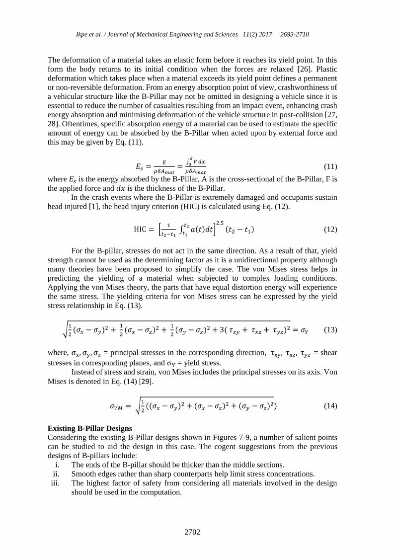
The deformation of a material takes an elastic form before it reaches its yield point. In this
form the body returns to its initial condition when the forces are relaxed [26]. Plastic
deformation which takes place when a material exceeds its yield point defines a permanent
or non-reversible deformation. From an energy absorption point of view, crashworthiness of
a vehicular structure like the B-Pillar may not be omitted in designing a vehicle since it is
essential to reduce the number of casualties resulting from an impact event, enhancing crash
energy absorption and minimising deformation of the vehicle structure in post-collision [27,
28]. Oftentimes, specific absorption energy of a material can be used to estimate the specific
amount of energy can be absorbed by the B-Pillar when acted upon by external force and
this may be given by Eq. (11).
𝐸𝑠 =𝐸
𝜌𝛿𝐴𝑚𝑎𝑡=
∫ 𝐹 𝑑𝑥𝛿
0
𝜌𝛿𝐴𝑚𝑎𝑡 (11)
where 𝐸𝑠 is the energy absorbed by the B-Pillar, A is the cross-sectional of the B-Pillar, F is
the applied force and 𝑑𝑥 is the thickness of the B-Pillar.
In the crash events where the B-Pillar is extremely damaged and occupants sustain
head injured [1], the head injury criterion (HIC) is calculated using Eq. (12).
HIC = [1
𝑡2−𝑡1 ∫ 𝑎(𝑡)𝑑𝑡
𝑡2
𝑡1]
2.5(𝑡2 − 𝑡1) (12)
For the B-pillar, stresses do not act in the same direction. As a result of that, yield
strength cannot be used as the determining factor as it is a unidirectional property although
many theories have been proposed to simplify the case. The von Mises stress helps in
predicting the yielding of a material when subjected to complex loading conditions.
Applying the von Mises theory, the parts that have equal distortion energy will experience
the same stress. The yielding criteria for von Mises stress can be expressed by the yield
stress relationship in Eq. (13).
√1
2(𝜎𝑥 − 𝜎𝑦)2 +
1
2(𝜎𝑥 − 𝜎𝑧)2 +
1
2(𝜎𝑦 − 𝜎𝑧)2 + 3( 𝜏𝑥𝑦 + 𝜏𝑥𝑧 + 𝜏𝑦𝑧)2 = 𝜎𝑌 (13)
where, σx, σy, σz = principal stresses in the corresponding direction, τxy, τxz, τyz = shear
stresses in corresponding planes, and σY = yield stress.
Instead of stress and strain, von Mises includes the principal stresses on its axis. Von
Mises is denoted in Eq. (14) [29].
𝜎𝑉𝑀 = √1
2((𝜎𝑥 − 𝜎𝑦)2 + (𝜎𝑥 − 𝜎𝑧)2 + (𝜎𝑦 − 𝜎𝑧)2) (14)
Existing B-Pillar Designs Considering the existing B-Pillar designs shown in Figures 7-9, a number of salient points
can be studied to aid the design in this case. The cogent suggestions from the previous
designs of B-pillars include:
i. The ends of the B-pillar should be thicker than the middle sections.
ii. Smooth edges rather than sharp counterparts help limit stress concentrations.
iii. The highest factor of safety from considering all materials involved in the design
should be used in the computation.

Design optimization of a B-pillar for crashworthiness of vehicle side impact
2703
Figure 7. Real Life example of Car B-Pillar [30].
Figure 8. Example of a B-pillar design [13].
Figure 9. Audi B-pillar reinforcements in Coventry University workshop.

Ikpe et al. / Journal of Mechanical Engineering and Sciences 11(2) 2017 2693-2710
2704
For safety purposes, the B-Pillar should help protect drivers from risks in the
occurrence of side impact scenarios. As such, safety regulations must be met. The FMVV
105 standard and EuroCAP regulations set out the criteria that a typical B-Pillar design must
meet. The designs in Figure 7-9 use reinforcements such that the B-Pillar has varying
thicknesses at various locations in the design. This was done to enhance the moment of
inertia. The design is sometimes influenced by material properties and manufacturing
processes. However, the cross-section of the structure has a role to play in both factors and
oftentimes becomes the maximised or minimised function in B-Pillar design. This is done
around the critical areas predetermined by the initial load case analysis.
RESULTS AND DISCUSSION
Table 3 represents the summary of the initial and final B-Pillar design analyses. Judging
from the results obtained for mass, displacement, and von Mises stress, there is a distinctive
difference in the values obtained from the original and final analyses, implying that the final
(optimised B-Pillar) B-Pillar analysis can perform optimally in severe conditions.
Table 3. Summary of the initial and final B-pillar analyses.
Description Initial Analysis Final Analysis (Optimisation)
Design
Name
B-Pillar
Max von
Mises stress
1646 MPa
Max von
Mises stress
673MPa
Load Case
140kN
Displacement
5.9mm
Displacement
2.39mm
Analysis
Static
Initial Mass
6kg
Final Mass
4.271kg
(a) (b)
Figure 10. Final design of the B-Pillar with reinforcement and load case.
The outer B-Pillar surface remained the same throughout the design process. The
reinforcement has similar physical properties to the outer surface of the B-pillar. The seam
weld was used in joining the reinforcements with the outer surface. As shown earlier in
Figures 6, the optimised B-Pillar design, however, had a mass of 4.271 kg with the
reinforcements making up about 1.716 kg of the total design compared to the original B-
Pillar which had a mass of 6 kg. The second moment of inertia of the final design was
1.929e-5 m4. In the first design, the use of spot welding made it difficult to produce the
design. Some of the designs that failed in the process are shown in Appendix 1. After
necessary adjustment, the design was done such that the factor of safety was within range,

Design optimization of a B-pillar for crashworthiness of vehicle side impact
2705
the structure remained within its elastic region throughout the test, and the maximum stress
was around 673 MPa. The final B-pillar design with reinforcement is shown in Figure 10
(a), while the load case on final B-pillar design with reinforcement is shown in Figure 10(b).
Appendix 1 represents some of the numerous difficult designs to be produced as a result of
the application of spot welding and may not have the required strength to resist the forces
acting on the B-pillar in crash scenarios. Appendix 2 shows the front view of the B-pillar
design while Appendix 3 shows the isometric view of the B-pillar design with a scale of 1:5
each.
(a) von Mises stress (b) Displacement
Figure 11. von Mises stress and maximum displacement of the final design.
The optimised design had four (4) reinforced layers replicating the original B-
Pillar. The four reinforcements also have different thicknesses. The thickness depends on
the nature of the stresses obtained from the initial analysis. Further modifications on the
design can be obtained from running an optimisation procedure for the B-Pillar on any
solver. As shown in Figure 11 (a), the maximum von Mises stress obtained for the
optimised B-Pillar design was 673 MPa, quite lower than the maximum von Mises stress
of 1646 MPa obtained for the original B-Pillar analysis. As shown in Figure 11(b), the
maximum displacement obtained from the optimised B-Pillar analysis was low (2.39 mm)
compared to displacement value (5.9mm) for the original B-Pillar. Applying a force of
140 kN, the B-Pillar produced resultant forces and moments along the x, y, and z
directions as follows; Fx = -3.013e-007 N, Fy = 1.400e+005 N, Fz = -1.555e-007 N, Mx
= -7.646e+004 Nxm, My = -1.285e-006 Nxm and Mz = -1.425e+003 Nxm. Ikpe et al.
[31] proposed four (4) B-Pillar conceptual designs and the selected design had a
maximum von Mises stress of 3.81e+003 MPa, the weight of 5.73 kg, and maximum
displacement of 13.8 mm which are comparably higher than the values obtained for
similar parameters in this study. Using virtual test to optimise a B-Pillar by changing the
B-Pillar material and thickness, Qiao and Shi [5] found out that increasing the material
thickness was not an ideal approach but changing the material from steel to aluminium

Ikpe et al. / Journal of Mechanical Engineering and Sciences 11(2) 2017 2693-2710
2706
alloy greatly improved the crashworthiness of the B-Pillar. However, studies conducted
by Parrish et al. [32] revealed that magnesium alloy can be optimised to improve
crashworthiness characteristics with over 50% weight reduction in the redesign part.
Contrarily, Lilehkoohi et al. [33] in their investigation proposed AISI1006 carbon steel
for B-Pillar crash impact test but this may compromise the lightweight requirement due
to its density which may contribute to fuel consumption rate of a given vehicle.
In all iterations, it was observed that the von Mises stress value was higher at the
fillets. Since the given B-pillar design was Class ‘A’ surface, no changes were made to
its geometry. However, modifying the filleted regions can possibly give better stress
dissipation characteristics to the B-pillar assembly. Using lightweight materials can
improve the vehicle fuel efficiency but could also compromise the strength of the B-pillar
depending on the mechanical properties of the material and this could be reanalysed
further.
CONCLUSIONS
Further developments can be carried out on the B-Pillar. However, this may require the
use of optimisation technique rather than taking more iteration. The optimisation
procedure will help ascertain points where reinforcements can be added as well as suggest
places on the B-Pillar where materials can be removed. The whole process of iterating
designs requires plenty of time. The optimisation technique will determine the load paths
and this helps define the amount of material that should be at different locations within
the design. The maximum stress on the B-Pillar was 673MPa and this was close to that
required for the 1.25 factor of safety. One paramount limitation in the FEA solver was
the ability to modify the meshes easily. This reduced the accuracy of the solutions
obtained as they are highly dependent on the mesh quality. A possible error in the solution
may also have resulted from accumulated approximations during the course of the
numerical computations.
ACKNOWLEDGEMENTS
The authors of this manuscript would like to express their gratitude to Coventry
University for providing the tools (used in achieving the objectives of this project-no.
M10MAE) and guidance in terms of tutorial classes.
REFERENCES
[1] Dakin GJ, Arbelaez RA, Nolan JM, Zuby DS, Lund AK. Insurance institute for
highway safety side impact crashworthiness evaluation program: Impact
configuration and rationale. 18th International Technical Conference on the
Enhanced Safety of Vehicles (CD-ROM). Washington: DC: National Highway
Traffic Safety Administration.; 2003.
[2] Bodin H, Berglund D. B-pillar for a vehicle. US 8292354 B2; 2015.
[3] SIMULIA. Prediction of b-pillar failure in automobile bodies. Retrieved from
http://www.3ds.Com/fileadmin/products/simulia/pdf/tech-briefs/auto-prediction-
of-b-pillar-failure-automobile-bodies-08.Pdf. 24 November, 2015.
[4] Borst D, Crisfield R, Remmers M, Verhoosel C. Nonlinear finite element analysis
of solids and structures: John Wiley & Sons; 2012.

Design optimization of a B-pillar for crashworthiness of vehicle side impact
2707
[5] Qiao WG, Shi WY. Simulation and optimization of b-pillar crashworthiness based
on virtual test. Applied Mechanics and Materials: Trans Tech Publ; 2014. p. 505-
6: 380-3.
[6] Lilehkoohi A, Faieza A, Sahari B, Nuraini A, Halali M. Crashworthiness
determination of side doors and b pillar of a vehicle subjected to pole side impact.
Applied Mechanics and Materials. 2014;663:552-6.
[7] Kamal M, Rahman MM. Finite element-based fatigue behaviour of springs in
automobile suspension. International Journal of Automotive and Mechanical
Engineering. 2014;10:1910-9.
[8] Ariffin AH, Solah MS, Azhar H, Isa M, Hafzi M, Rahman MK, et al. Development
of mobile deformable barrier for side impact crashworthiness evaluation in asean
new car assessment programme (ASEAN NCAP). In Applied Mechanics and
Materials. 2014;663:562-6.
[9] Ahmad Z, Nagel G, Thambiratnam D. Inclusion of tapered tubes in enhancing the
crash performance of automotive frontal structures. Key Engineering Materials:
Trans Tech Publ; 2013. p. 1-6.
[10] Naghipour M, Nemati M, Doostdar H. Experimental study and modeling of
reinforced concrete beams strengthened by post-tensioned external reinforcing
bars. International Journal of Engineering. 2010;23:127-44.
[11] Huetter J. 2016 honda hr-v is ultra-popular -and 27 percent ultra-high-strength
steel. Retrievd from http://www.Repairerdrivennews.Com/2015/06/24/2016-
honda-hr-v-is-ultra-popular-and-27-percent-ultra-high-strength-steel/.
[12] EURONCAP. Car to car side impact euro ncap - for safer car crash test safety
rating. Retrieved from http://www.Euroncap.Com/content-web-page/106f41f7-
d486-46bf-bfbc-80fb4c79f679/car-to-car-side-impact.Aspx.
[13] Carney D. The new crash test that will change your next car. Retried from
http://www.Popularmechanics.Com/cars/a8070/the-new-crash-test-that-will-
chang-your-next-car-11980742/. 14 July, 2015.
[14] Njuguna J. The application of energy-absorbing structures on side impact
protection systems. International Journal of Computer Applications in
Technology. 2011;40:280-7.
[15] Jawi ZM, Isa MHM, Mohamed N, Awang A, Osman MR. A systemic analysis of
the usage of safety items among malaysian private vehicle users. Journal of
Mechanical Engineering and Sciences. 2016;10:2262-74.
[16] Reddy S. Modeling and analysis of a composite b-pillar for side-impact protection
of occupants in a sedan: Wichita State Uniersity, USA.; 2003.
[17] Rahman N, Abdullah S, Abdullah M, Zamri W, Omar M, Sajuri Z. Energy
absorption capability and deformation of laminated panels for armoured vehicle
materials. International Journal of Automotive and Mechanical Engineering.
2016;13:3657-68.
[18] Analysis FRFE. In a. N. Gent, engineering with rubber: How to design rubber
components. Munich: Hanser Publishers; 2011.
[19] Reddy JN. An introduction to the finite element method: McGraw-Hill New York;
2005.
[20] Kamal M, Rahman MM. An integrated approach for fatigue life estimation based
on continuum mechanics theory and genetic algorithm. International Journal of
Automotive and Mechanical Engineering. 2015;11:2756-70.

Ikpe et al. / Journal of Mechanical Engineering and Sciences 11(2) 2017 2693-2710
2708
[21] Rahman MM, Ariffin AK, Rejab MRM, Kadirgama K, Noor MM. Multiaxial
fatigue behavior of cylinder head for a free piston linear engine. Journal of
Applied Sciences. 2009;9:2725-34.
[22] Blackwell W. Retrieved from
http://www.Colorado.Edu/engineering/cas/courses.D/ifem.D/. 4 March, 2013.
[23] Kazerouni S, Saidi A, Mohammadi M. Buckling analysis of thin functionally
graded rectangulare plates with two opposite edges simply supported.
International Journal of Engineering Transactions B: Applications. 2010;23:179-
92.
[24] NAFEMS. The importance of mesh convergence- Part 1 Engineering analysis and
simulation-FEA, finite element analysis, CFD, computational fluid dynamics and
simulation.
Retrieved from http://nafems.Org/join/resources/knowledgebase/001/.Htm. 6
September, 2015.
[25] Frederick A, Dominic J. Strength and stiffness of engineering systems. Springer,
New York Google Scholar; 2009.
[26] Hicks TG. Handbook of Civil Engineering Calculations; 2007.
[27] Ahmad Z, Othman M. Energy absorption performance of a rain forest vehicle
under frontal impact. Journal of Mechanical Engineering and Sciences.
2014;6:807-17.
[28] Elkady M, Elmarakbi A, MacIntyre J. Integration of vehicle dynamics control
systems with an extendable bumper for collision mitigation. International Journal
of Automotive and Mechanical Engineering. 2015;12:2893-913.
[29] Budynas RG, Nisbett JK. Shigley's mechanical engineering design: McGraw-Hill
New York; 2008.
[30] Lombardi M. Body b-pillar. Retrieved from
http://www.Primapower.Com/media/uploads/editorialtext/docs/85bec587ceed83
1feff1e11f1f82c456.Pdf. 15 July, 2008.
[31] Ikpe AE, Orhorhoro EK, Gobir A. Design and reinforcement of a b-pillar for
occupants safety in conventional vehicle applications. International Journal of
Mathematical, Engineering and Management Science. 2017;2:37-52.
[32] Parrish A, Rais-Rohani M, Najafi A. Crashworthiness optimization of vehicle
structures with magnesium alloy parts. International Journal of Crashworthiness.
2012;17:259-81.
[33] Lilehkoohi A, Faieza A, Sahari B, Nuraini A, Halali M. Effect of material on
crashworthiness for side doors and b pillar subjected to euro ncap side impact
crash test. Journal of Advanced Letters. 2013;19:359-62.

Design optimization of a B-pillar for crashworthiness of vehicle side impact
2709
APPENDICES
Appendix 1. One of the attempts achieved while trying to reduce the von-Mises stress
on the B-pillar.
Appendix 2. Front view of the B-pillar design

Ikpe et al. / Journal of Mechanical Engineering and Sciences 11(2) 2017 2693-2710
2710
Appendix 3. Isometric view of the B-pillar design