Design optimization analysis of an anti-backlash geared ...
15
Mech. Sci., 12, 305–319, 2021 https://doi.org/10.5194/ms-12-305-2021 © Author(s) 2021. This work is distributed under the Creative Commons Attribution 4.0 License. Design optimization analysis of an anti-backlash geared servo system using a mechanical resonance simulation and experiment Lianchao Zhang 1 , Hongbo Liao 1,2 , Dapeng Fan 1 , Shixun Fan 1 , and Jigui Zheng 3 1 College of Intelligence Science and Technology, National University of Defense Technology, Changsha, 410073, People’s Republic of China 2 Northwest Institute of Nuclear Technology, Xi’an, 710024, People’s Republic of China 3 Beijing Institute of Precise Mechatronics and Controls, Beijing, 100076, People’s Republic of China Correspondence: Lianchao Zhang ([email protected]) Received: 30 May 2020 – Revised: 8 December 2020 – Accepted: 31 January 2021 – Published: 17 March 2021 Abstract. In many mechatronic systems, gear transmission chains are often used to transmit motion and power between motors and loads, especially for light, small but large torque output systems. Gear transmission chains will inevitably bring backlash as well as elasticity of shafts and meshing teeth. All of these nonlinear factors will affect the performance of mechatronic systems. Anti-backlash gear systems can reduce the transmission error, but elasticity has to be considered too. The aim of this paper is to find the key parameters affecting the resonance and anti-resonance frequencies of anti-backlash gear systems and then to give the design optimization methods of improving performance, both from element parameters and mechanical designing. The anti-backlash geared servo system is modeled using a two-inertia approximate model; a method of computing the equivalent stiffness of anti-backlash gear train is proposed, which comprehensively considers the total backlash of trans- mission chain, gear mesh stiffness, gear shaft stiffness and torsional spring stiffness. With the s -domain block diagram model of the anti-backlash geared servo system, the influences of four main factors on the resonance and anti-resonance frequencies of system are analyzed by simulation according to the frequency response, and the simulation analysis results dependent on torsional spring stiffness of anti-backlash gear pair and load moment of inertia variation are verified by the experiment. The errors between simulation and experimental results are less than 10 Hz. With these simulation and experiment results, the design optimization methods of improving the resonance and anti-resonance frequencies such as designing the center distance adjusting mechanism to reduce the initial total backlash, increasing the stiffness of torsional spring and lightweight design of load are proposed in engineering applications. 1 Introduction As a primary method of mechanical transmission, gear trans- mission is widely used in the precision servo mechanism field, such as robot, seeker and inertially stabilized platforms, which have the requirements of fast response, high position- ing accuracy and good stability (Chung et al., 2010; Hilkert, 2008; Slamani and Bonev, 2013; Baek et al., 2003a). How- ever, the traditional gear transmission mechanisms have the disadvantages of backlash, friction and elasticity, which limit the performance of response, positioning accuracy and sta- bility, and they are seriously restricted in the application of high-precision servo systems. To solve these problems, researchers and engineers pro- posed several solutions, one of which is to choose the princi- ple of the transmission mechanism. Using the harmonic gear can eliminate backlash effectively, but friction and flexibil- ity of the transmission chain are increased (Vassileva et al., 2011; Masoumi and Alimohammadi, 2013), and using direct drive principle can omit the transmission chain. The motor and load are connected directly. Hence, the friction is re- duced, backlash is eliminated, and the mechanical stiffness Published by Copernicus Publications.
Transcript of Design optimization analysis of an anti-backlash geared ...

Mech. Sci., 12, 305–319, 2021https://doi.org/10.5194/ms-12-305-2021© Author(s) 2021. This work is distributed underthe Creative Commons Attribution 4.0 License.
Design optimization analysis of an anti-backlash gearedservo system using a mechanical resonance simulation
and experiment
Lianchao Zhang1, Hongbo Liao1,2, Dapeng Fan1, Shixun Fan1, and Jigui Zheng3
1College of Intelligence Science and Technology, National University of Defense Technology, Changsha,410073, People’s Republic of China
2Northwest Institute of Nuclear Technology, Xi’an, 710024, People’s Republic of China3Beijing Institute of Precise Mechatronics and Controls, Beijing, 100076, People’s Republic of China
Correspondence: Lianchao Zhang ([email protected])
Received: 30 May 2020 – Revised: 8 December 2020 – Accepted: 31 January 2021 – Published: 17 March 2021
Abstract. In many mechatronic systems, gear transmission chains are often used to transmit motion and powerbetween motors and loads, especially for light, small but large torque output systems. Gear transmission chainswill inevitably bring backlash as well as elasticity of shafts and meshing teeth. All of these nonlinear factorswill affect the performance of mechatronic systems. Anti-backlash gear systems can reduce the transmissionerror, but elasticity has to be considered too. The aim of this paper is to find the key parameters affecting theresonance and anti-resonance frequencies of anti-backlash gear systems and then to give the design optimizationmethods of improving performance, both from element parameters and mechanical designing. The anti-backlashgeared servo system is modeled using a two-inertia approximate model; a method of computing the equivalentstiffness of anti-backlash gear train is proposed, which comprehensively considers the total backlash of trans-mission chain, gear mesh stiffness, gear shaft stiffness and torsional spring stiffness. With the s-domain blockdiagram model of the anti-backlash geared servo system, the influences of four main factors on the resonance andanti-resonance frequencies of system are analyzed by simulation according to the frequency response, and thesimulation analysis results dependent on torsional spring stiffness of anti-backlash gear pair and load momentof inertia variation are verified by the experiment. The errors between simulation and experimental results areless than 10 Hz. With these simulation and experiment results, the design optimization methods of improving theresonance and anti-resonance frequencies such as designing the center distance adjusting mechanism to reducethe initial total backlash, increasing the stiffness of torsional spring and lightweight design of load are proposedin engineering applications.
1 Introduction
As a primary method of mechanical transmission, gear trans-mission is widely used in the precision servo mechanismfield, such as robot, seeker and inertially stabilized platforms,which have the requirements of fast response, high position-ing accuracy and good stability (Chung et al., 2010; Hilkert,2008; Slamani and Bonev, 2013; Baek et al., 2003a). How-ever, the traditional gear transmission mechanisms have thedisadvantages of backlash, friction and elasticity, which limitthe performance of response, positioning accuracy and sta-
bility, and they are seriously restricted in the application ofhigh-precision servo systems.
To solve these problems, researchers and engineers pro-posed several solutions, one of which is to choose the princi-ple of the transmission mechanism. Using the harmonic gearcan eliminate backlash effectively, but friction and flexibil-ity of the transmission chain are increased (Vassileva et al.,2011; Masoumi and Alimohammadi, 2013), and using directdrive principle can omit the transmission chain. The motorand load are connected directly. Hence, the friction is re-duced, backlash is eliminated, and the mechanical stiffness
Published by Copernicus Publications.

306 L. Zhang et al.: Optimization of an anti-backlash geared system using resonance analysis
is very high (Asada et al., 1989; Su et al., 2002). However,the direct drive is not suitable for small, light but large outputtorque systems.
The elasticity of transmission chain is also an importantproblem which influences the bandwidth of servo systems.There are several mechanical components that have elasticitywhich can influence the transmission error and performanceof the gear transmission chain: transmission shaft elastic-ity (Dwivedula and Pagilla, 2012), support bearing elasticity(Walha et al., 2009; Wang et al., 2011, 2016), gear meshingelasticity caused by gear tooth stiffness (Jia et al., 2003; Li etal., 2020) and even the gear meshing stiffness vary with time(Shi et al., 2020). All these factors make the transmissionchain not ideally rigid, but flexible, under specific dynamicconditions, the systems will generate undesirable vibration.Moreover, the elasticity and backlash will have combined in-fluence on the servo system.
Some researchers tried to solve these problems directlyfrom the control aspect without changing any mechanical de-sign. Kolnik and Agranovich (2012) estimated the equivalentbacklash and torsional torque disturbances using disturbanceobserver (DOB). The torque is then compensated in the innerfeedback loop, which decreased the vibrations caused by thebacklash and the transmission shaft elasticity, but this com-pensation algorithm is just simulated using a transmissionsystem model with a very small backlash. Yang et al. (2016)proposed a robust shaft torque compensator in a two-inertiaelastic system with backlash; this compensator can make theservo system behave like a rigid control system with singlemoment of inertia by adjusting the feedback coefficient, andthis control method can suppress mechanical resonance sig-nificantly.
Another method to solve the backlash problem is us-ing anti-backlash mechanisms. Different anti-backlash geartransmissions were designed to decrease the influence ofbacklash in some research. Most of them mainly focus onmechanism structure design, transmission precision analysisand application. Several anti-backlash mechanisms were in-vestigated; the advantages and disadvantages of these meth-ods were analyzed (Hale and Slocum, 1994). Shi and Yang(2000) enumerated several types of the anti-backlash geartrain mechanisms, and the preload of torsional spring of dou-ble gear mechanism was calculated. Allan and Levy (1980)deduced the formula of minimum preload torque in the de-sign of spring-loaded anti-backlash gear. Yang et al. (2013)deduced the dynamic model of anti-backlash gear consid-ering friction and time-varying mesh stiffness. These men-tioned studies provide theories for us about the calculation ofthe comprehensive equivalent stiffness of the anti-backlashgear train.
Some researchers modeled the multistage general spur-gear trains and analyzed the frequency response characteris-tics of them. Baek et al. (2003b) considered the dynamics ofa two-stage general spur-gear train as a two-inertia approx-imate model; the influences of motor input voltage and to-
tal backlash on the resonance and anti-resonance frequenciesof system were analyzed. Especially the contribution rate ofeach stage backlash to the resonance and anti-resonance fre-quencies were obtained. Zhou et al. (2009) built the model ofmultistage general spur-gear train based on two-inertia ap-proximate model, which contained the backlash, gear shaftstiffness and gear mesh stiffness. The influences of back-lash and reduction ratio on frequency response characteris-tics of system were analyzed. Based on the modeling methodof multistage general spur-gear train, some researchers stud-ied the model of multistage anti-backlash gear train. Kwonet al. (2004) built a two-inertia model of three-stage anti-backlash geared servo system. A normalized describing func-tion was used to describe the backlash; the formulas of res-onance and anti-resonance frequencies were deduced. How-ever, the model did not consider the torsional spring. The re-lation between the main gears and freewheel gears was notclear, and only the motor output torque influence on the fre-quency response characteristics of system was analyzed.
In the anti-backlash geared servo systems, the resonanceand anti-resonance frequencies of system may be close tothe servo bandwidth, which can limit the performance of re-sponse and stability of the servo system (Hale and Slocum,1994; Shim et al., 2008; Jesper, 2004). Acceleration feed-back loop and notch filter are used in some research to sup-press the mechanism resonance (Lee et al., 2012; Szabat andOrlowska-Kowalska, 2007; George and Gao, 2001; George,2004; Hoogendijk et al., 2014). However, If the notch fil-ter’s center frequency is different from the actual resonantfrequency, the closed-loop system could exhibit increased os-cillations or even become unstable (Bahn et al., 2016). Thecenter frequency of the notch filter must be the same as theresonance frequency accurately, which is difficult when theresonance frequency is approximately equal to the crossoverfrequency of the speed loop; the acceleration feedback alsoincreases the cost of system. Therefore, the problem needsto be solved by other methods. The best one is to make theresonance and anti-resonance frequencies of the system farfrom the bandwidth of the speed loop. The literature showsthat current research mainly focuses on the multistage gen-eral spur-gear servo system, and frequency response charac-teristic analyses are concentrating on the total backlash ofgear train, gear shaft stiffness, gear mesh stiffness and motorinput voltage. However, the literature about the anti-backlashgear train model is rare; the key factors affecting frequencyresponse characteristics are not completely clear.
In this paper, a multistage torsional spring-loaded anti-backlash gear transmission chain is designed to eliminatethe backlash and to achieve a large output torque from asmall input torque. Based on this transmission chain, this pa-per aims to find the key parameters affecting the resonanceand anti-resonance frequencies of anti-backlash gear systemsand to propose design optimization methods of improvingperformance, both from element parameters and mechanicaldesigning. The two-inertia model of torsional spring-loaded
Mech. Sci., 12, 305–319, 2021 https://doi.org/10.5194/ms-12-305-2021

L. Zhang et al.: Optimization of an anti-backlash geared system using resonance analysis 307
anti-backlash gear train will be built based on the modelof the general spur-gear train; a new method of computingequivalent stiffness of the anti-backlash gear train will beproposed, which considers the total backlash of transmis-sion chain, gear mesh stiffness, gear shaft stiffness and tor-sional spring stiffness comprehensively. Then the s-domainblock diagram model of the anti-backlash geared servo sys-tem will be built. With this model, the influences of differ-ent parameters of the four main factors on the resonance andanti-resonance frequencies of system are analyzed by simula-tion. The simulation results will be validated by experiments.The design optimization methods of improving the resonanceand anti-resonance frequencies are according to the simula-tion and experiment results.
The structure of this paper is as follows. The model of anti-backlash geared servo system is established, the proposedequivalent stiffness computation method of anti-backlashgear train is analyzed, the formulas of key parameters are de-duced, and the s-domain block diagram of the anti-backlashgeared servo system is given in Sect. 2. The influences of dif-ferent parameters of total backlash, torsional spring stiffness,load moment of inertia, gear mesh stiffness, and gear shaftstiffness variation on the resonance and anti-resonance fre-quencies of system are analyzed by simulation in Sect. 3.The simulation results of load moment of inertia and tor-sional spring stiffness variation are validated by experimentsin Sect. 4. Finally, conclusions are obtained in Sect. 5.
2 Modeling
2.1 System description
The anti-backlash geared servo system is composed of a DCmotor, four-stage anti-backlash gear train, load, sensors, mo-tor driver and motion controller, which is shown in Fig. 1.This mechanism is applied in a two-axis inertially stabilizedplatform; the gyroscope closed loop is designed to isolate thecarrier disturbances.
In Fig. 1, the anti-backlash gear train is mainly composedof driving gear (1), main gears (2, 3, 4, 5, 6, 7, 8), freewheelgears (2′, 3′, 4′, 5′, 6′, 7′, 8′), torsional spring and bearing.The driving gear is connected to the motor. Following themotor rotation, the main gears are fixed on the shafts, andthe freewheel gears are nested on the shafts, which rotatearound the shafts. One of the torsional spring butts is fixedon the last stage main gear (8). Another one is fixed on thelast stage freewheel gear (8′). A certain preload is appliedon the torsional spring to guarantee the main and freewheelgears contact with the positive or negative teeth surface ofthe driving gear, respectively, so as to eliminate the back-lash. In the anti-backlash geared servo system, the elastic-ity of transmission chain can not be neglected, which makesthe machine resonance close to the bandwidth of the gyro-scope closed loop. Therefore, the key factors affecting thefrequency response characteristics of system need to be ana-
Figure 1. Schematic of the anti-backlash geared servo system. V isa tachometer, P is a potentiometer as load position sensor, and G isa gyroscope.
Figure 2. Equivalent model of the anti-backlash geared servo sys-tem.
lyzed, which are helpful to the design, assembly and applica-tion of the anti-backlash gear train.
2.2 Model of the anti-backlash geared servo system
In the multistage anti-backlash gear train, the transmissioncomponents can be treated as a single, composite, equivalenttorsional spring that interconnects with the motor and load,which is shown in Fig. 2.
Where Jm is the equivalent moment of inertia on the mo-tor shaft, it mainly contains the moment of inertia of motorrotor, equivalent moment of inertia of each stage main andfreewheel gears and shafts (not containing the last stage); θmis the angular displacement of the motor; Tm is the outputtorque of the motor, its direction is the left arrow in the fig-ure; Tmf is the total equivalent friction torque; Tsm is the tor-sional torque applied on the motor by the transmission train,
https://doi.org/10.5194/ms-12-305-2021 Mech. Sci., 12, 305–319, 2021
308 L. Zhang et al.: Optimization of an anti-backlash geared system using resonance analysis
Tmf and Tsm direction is the arrow in the middle in the figure,which is the reverse direction to the Tm direction; Tl is thedriving torque of the last stage shaft on the load; its directionis the right arrow in the figure, the same direction with theTm direction; Jl is the equivalent moment of inertia of load;it mainly contains the moment of inertia of the last stage mainand freewheel gears, the shaft and the load; θl is the angulardisplacement of the load;Ka is the equivalent stiffness of theanti-backlash gear train.
The output torque of the motor is controlled. Namely, themotor driver is operated in the current closed-loop mode, andthe controller of current loop is a proportional plus integral(PI). The composite model of motor driver and motor can bewritten as
Ua = RaIa+LadIa
dt+Ea (1a)
Ea =Keθ̇m (1b)Tm =KtIa (1c)
Ua =KpKpwm(Ic− Ia)+KIKpwm
t∫0
(Ic− Ia) dt, (1d)
where Ua is the input voltage of the motor; Ra is the re-sistance of the motor armature; La is the inductance of themotor armature; Ia is the current of the motor; Ea is theback electromotive force (EMF); Ke is the back electromo-tive force coefficient; Kt is the torque coefficient; Kp is theproportional gain of the current loop controller; KI is the in-tegral gain of the current loop controller; Kpwm is the motordriver gain; Ic is the reference signal of the current loop.
In the spur-gear train, if the backlash is not considered, thetransmission torque can be calculated by
Tl =Ka
(θm/
(n∏i=1Ni
)− θl
)(2a)
Tsm = Tl/
(n∏i=1Ni
), (2b)
where Ni is the ratio of each stage gear train, Tl is the torquetransmitted to the load from the last stage transmission shaft,Ka is the comprehensive stiffness of transmission train, andn is the stages number of the gear train.
However, the backlash can not be neglected in the system.If the transmission angle error 1θ is small enough, the mo-tor and load does not contact in the backlash area. The trans-mission torque of gear train can be rewritten as (Nordin andGutman, 2002)
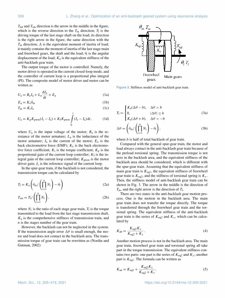
Figure 3. Stiffness model of anti-backlash gear train.
Tl =
Ka(1θ − b), 1θ > b
0, |1θ | ≤ b
Ka(1θ + b), 1θ <−b
(3a)
1θ =
(θm/
(n∏i=1Ni
)− θl
), (3b)
where b is half of total backlash of gear train.Compared with the general spur-gear train, the motor and
load always contact in the anti-backlash gear train because ofthe preload torsional spring. The transmission torque is notzero in the backlash area, and the equivalent stiffness of thebacklash area should be considered, which is different withthe spur-gear train. Assuming that the equivalent stiffness ofmain gear train is Keq1, the equivalent stiffness of freewheelgear train is Keq2, and the stiffness of torsional spring is Kx .Then, the stiffness model of anti-backlash gear train can beshown in Fig. 3. The arrow in the middle is the direction ofTm, and the right arrow is the direction of Tl.
There are two states in the anti-backlash gear motion pro-cess. One is the motion in the backlash area. The maingear train does not transfer the torque directly. The torqueis transferred through the freewheel gear train and the tor-sional spring. The equivalent stiffness of the anti-backlashgear train is the series of Keq2 and Kx , which can be calcu-lated by
Kab =Keq2Kx
Keq2+Kx. (4)
Another motion process is not in the backlash area. The maingear train, freewheel gear train and torsional spring all takepart in the torque transmission. The equivalent stiffness con-tains two parts: one part is the series ofKeq2 andKx ; anotherpart is Keq1. The formula can be written as
Kan =Keq1+Keq2Kx
Keq2+Kx. (5)
Mech. Sci., 12, 305–319, 2021 https://doi.org/10.5194/ms-12-305-2021
L. Zhang et al.: Optimization of an anti-backlash geared system using resonance analysis 309
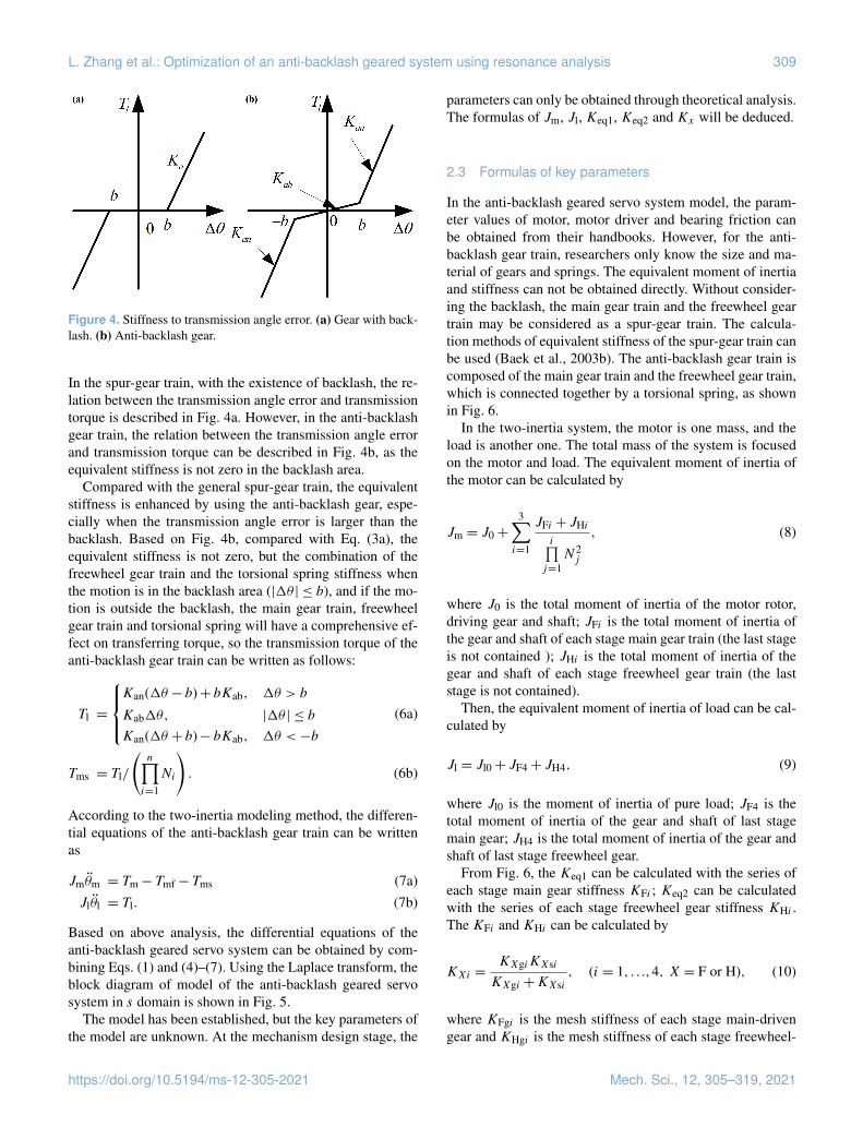
Figure 4. Stiffness to transmission angle error. (a) Gear with back-lash. (b) Anti-backlash gear.
In the spur-gear train, with the existence of backlash, the re-lation between the transmission angle error and transmissiontorque is described in Fig. 4a. However, in the anti-backlashgear train, the relation between the transmission angle errorand transmission torque can be described in Fig. 4b, as theequivalent stiffness is not zero in the backlash area.
Compared with the general spur-gear train, the equivalentstiffness is enhanced by using the anti-backlash gear, espe-cially when the transmission angle error is larger than thebacklash. Based on Fig. 4b, compared with Eq. (3a), theequivalent stiffness is not zero, but the combination of thefreewheel gear train and the torsional spring stiffness whenthe motion is in the backlash area (|1θ | ≤ b), and if the mo-tion is outside the backlash, the main gear train, freewheelgear train and torsional spring will have a comprehensive ef-fect on transferring torque, so the transmission torque of theanti-backlash gear train can be written as follows:
Tl =
Kan(1θ − b)+ bKab, 1θ > b
Kab1θ, |1θ | ≤ b
Kan(1θ + b)− bKab, 1θ <−b
(6a)
Tms = Tl/
(n∏i=1Ni
). (6b)
According to the two-inertia modeling method, the differen-tial equations of the anti-backlash gear train can be writtenas
Jmθ̈m = Tm− Tmf− Tms (7a)Jlθ̈l = Tl. (7b)
Based on above analysis, the differential equations of theanti-backlash geared servo system can be obtained by com-bining Eqs. (1) and (4)–(7). Using the Laplace transform, theblock diagram of model of the anti-backlash geared servosystem in s domain is shown in Fig. 5.
The model has been established, but the key parameters ofthe model are unknown. At the mechanism design stage, the
parameters can only be obtained through theoretical analysis.The formulas of Jm, Jl, Keq1, Keq2 and Kx will be deduced.
2.3 Formulas of key parameters
In the anti-backlash geared servo system model, the param-eter values of motor, motor driver and bearing friction canbe obtained from their handbooks. However, for the anti-backlash gear train, researchers only know the size and ma-terial of gears and springs. The equivalent moment of inertiaand stiffness can not be obtained directly. Without consider-ing the backlash, the main gear train and the freewheel geartrain may be considered as a spur-gear train. The calcula-tion methods of equivalent stiffness of the spur-gear train canbe used (Baek et al., 2003b). The anti-backlash gear train iscomposed of the main gear train and the freewheel gear train,which is connected together by a torsional spring, as shownin Fig. 6.
In the two-inertia system, the motor is one mass, and theload is another one. The total mass of the system is focusedon the motor and load. The equivalent moment of inertia ofthe motor can be calculated by
Jm = J0+
3∑i=1
JFi + JHii∏
j=1N2j
, (8)
where J0 is the total moment of inertia of the motor rotor,driving gear and shaft; JFi is the total moment of inertia ofthe gear and shaft of each stage main gear train (the last stageis not contained ); JHi is the total moment of inertia of thegear and shaft of each stage freewheel gear train (the laststage is not contained).
Then, the equivalent moment of inertia of load can be cal-culated by
Jl = Jl0+ JF4+ JH4, (9)
where Jl0 is the moment of inertia of pure load; JF4 is thetotal moment of inertia of the gear and shaft of last stagemain gear; JH4 is the total moment of inertia of the gear andshaft of last stage freewheel gear.
From Fig. 6, the Keq1 can be calculated with the series ofeach stage main gear stiffness KFi ; Keq2 can be calculatedwith the series of each stage freewheel gear stiffness KHi .The KFi and KHi can be calculated by
KXi =KXgiKXsi
KXgi +KXsi, (i = 1, . . .,4, X = F or H), (10)
where KFgi is the mesh stiffness of each stage main-drivengear and KHgi is the mesh stiffness of each stage freewheel-
https://doi.org/10.5194/ms-12-305-2021 Mech. Sci., 12, 305–319, 2021

310 L. Zhang et al.: Optimization of an anti-backlash geared system using resonance analysis
Figure 5. Block diagram of the anti-backlash geared servo system in s domain.
Figure 6. Schematic of the anti-backlash gear train.
driven gear. They can be calculated by (Zhou et al., 2009)
KXgi = 0.0136Ed2XgiWicos2λ (11)
(i = 1, . . .,4, X = F or H),
where E is Young’s modulus of the gears; dXgi is the pitchcircle diameter of each gear; Wi is the width of each gear; λis the pressure angle of the gears.KFsi is the stiffness of each stage main gear shaft, andKHsi
is the stiffness of each stage freewheel gear shaft. They canbe calculated by (Zhou et al., 2009)
KXsi =πGd4
Xsi32LXsi
, (i = 1, . . .,4, X = F or H), (12)
where G is the shear modulus of the gear shafts; dXsi is thediameter of each gear shaft; LXsi is the length of each gearshaft. Based on the relations between the input and outputtorque of anti-backlash gear train, formulas Keq1 and Keq2
can be written as
Keq1 =
(KF1KF2KF3KF4(N2N3N4)2
)(13)
/
(KF1KF2KF3(N2N3N4)2
+KF1KF2(N2N3)2
+KF1KF3(N2)2+KF2KF3
)Keq2 =
(KH1KH2KH3KH4(N2N3N4)2
)(14)
/
(KH1KH2KH3(N2N3N4)2
+KH1KH2(N2N3)2
+KH1KH3(N2)2+KH2KH3
).
From Fig. 6, the freewheel gear train is connected to the maingear train through a torsional spring. The torque is transferredby both the freewheel gear train and the torsional spring inthe backlash area, so the stiffness of torsional spring needs tobe considered in the model. The structure of torsional springis shown in Fig. 7, which is an arc spring, with a rectangularsection and the same material as the gears.
Assuming that a force P is applied perpendicular to thecenter line of the arc spring vertically, the deformation is δ,according to the principle of virtual work, the δ can be writtenas
δ =
π∫α
M(ϕ)M̄(ϕ)R dϕEI
, (15)
where α is half of the initial opening angle of arc spring infree state; R is the radius of the arc spring; I is the mo-ment of inertia of the spring’s rectangular section. M(ϕ)=
Mech. Sci., 12, 305–319, 2021 https://doi.org/10.5194/ms-12-305-2021

L. Zhang et al.: Optimization of an anti-backlash geared system using resonance analysis 311
Table 1. Parameters values of the anti-backlash geared servo system.
Variable name (unit) Value
Motor resistance Ra (�) 4.9Motor inductance La (mH) 0.148Torque sensitivity Kt (NmA−1) 0.02Back-EMF constant Ke (Vs rad−1) 0.02Proportional gain Kp 135.4Integral gain KI 90 890Motor driver gain Kpwm 2.4Gear ratio N1/N2/N3/N4 2/2.5/3.6/5Initial backlash b (◦) 0.15Pressure angle of gears λ (◦) 20Gears’ and torsional spring’s Young’s modulus E (GPa) 205Shear modulus of gears G (GPa) 80Pitch circle diameter of each stage-driven gear dXg1/dXg2/dXg3/dXg4 (mm) 20/25/36/60Width of each stage-driven gear W1/W2/W3/W4 (mm) 4.5/5.9/6.3/8.4Diameter of each stage gear shaft dXs1/dXs2/dXs3/dXs4 (mm) 2.5/4/6/12Length of each stage gear shaft LXs1/LXs2/LXs3/LXs4 (mm) 21.5/22/31/75Width of the rectangular section of arc torsional spring c (mm) 2.5Height of the rectangular section of arc torsional spring h (mm) 3.0Radius of the arc torsional spring R (mm) 25Half of the initial opening angle of arc spring in free state, α (◦) 20The total moment of inertia of the motor rotor, driving gear and shaft J0 (kgmm2) 1.3Moment of inertia of the second stage shaft and gears JF1+ JH1 (kgmm2) 0.56Moment of inertia of the third stage shaft and gears JF2+ JH2 (kgmm2) 1.6Moment of inertia of the fourth stage shaft and gears JF3+ JH3 (kgmm2) 7.4Moment of inertia of the fifth stage shaft and gears JF4+ JH4 (kgmm2) 21.7Moment of inertia of the pure load Jl0 (kgmm2) 945
Figure 7. Structure of the arc torsional spring.
PR(cosα− cosϕ), and M̄(ϕ)= R(cosα− cosϕ). Substitut-ing these equations into Eq. (15), δ can be rewritten as
δ =PR3
EI
[(π −α)(0.5+ cos2α)+ 0.75sin2α
]. (16)
If we let V = (π−α)(0.5+cos2α)+0.75sin2α, then Eq. (16)can be rewritten as
δ =PR3V
EI, (17)
where I can be calculated by
I =ch3
12, (18)
where c is the width of the arc spring’s rectangular section; his the height of the arc spring’s rectangular section.
Equation (17) can be rewritten as
P =EI
VR3 δ. (19)
When force P is applied on the spring, the variation value ofthe opening angle is 1α. If 1α is small enough, sin1α =1α = δ/R, then δ = R1α. Substituting this equation intoEq. (19), the stiffness of the torsional spring can be writtenas
Kx =T
1α=PR cosα1α
=EI cosαVR
, (20)
where T the torque generated by force P around the centerof the arc spring.
https://doi.org/10.5194/ms-12-305-2021 Mech. Sci., 12, 305–319, 2021

312 L. Zhang et al.: Optimization of an anti-backlash geared system using resonance analysis
Based on the above analysis, the values of key parametersof the system – Jm, Jl, Keq1, Keq2 and Kx – are obtainedthrough Eqs. (8), (9), (13), (14) and (20). Now, with theseparameters and the block diagram in Fig. 5, the influences ofkey parameters on the frequency response characteristics ofthe anti-backlash geared servo system will be simulated andanalyzed.
3 Simulation
The simulation model of the anti-backlash geared servo sys-tem is built in Fig. 5. The values of basic parameters in themodel are shown in Table 1, and parameter values of com-puted variables are shown in Table 2. As the input of sys-tem, the excitation signal is a chirp sinusoidal signal; the fre-quency ranges from 1 to 300 Hz; the response signal is theangular velocity of the motor, which is the output of sys-tem. The sampling time interval is 0.2 ms. The bode diagramof input/output can be obtained. The influences of backlash,torsional spring stiffness, load, gear mesh stiffness and gearshaft stiffness variation on the frequency response character-istics of system can be obtained.
3.1 The effect of backlash
In the anti-backlash geared servo system, if changing themagnitude of backlash only and other model parametersshown in Tables 1 and 2, the backlash ranges from 0.01 to0.5◦. The influence of backlash variation on the frequencyresponse characteristics of system is shown in Fig. 8. Thebacklash of the anti-backlash gear train is the total backlashbefore the torsional spring installation, which can be adjustedby the center distance between the driving and driven gear.When the torsional spring is fixed on the last stage main gearand freewheel gear, the space backlash of anti-backlash geartrain is very small but not completely eliminated.
The anti-resonance and resonance frequencies decreasewith the increase of backlash. When the backlash rangesfrom 0.01 to 0.5◦, the anti-resonance frequency ranges from170 to 60 Hz, and the resonance frequency ranges from 190to 70 Hz. The results show that the anti-resonance and reso-nance frequencies can be adjusted at a large range by chang-ing the magnitude of backlash. However, in the practical sys-tem, if there is no center distance adjusting mechanism, thetotal backlash is decided by the assembly technology. It isdifficult to control the magnitude of backlash in the assemblyprocess. Therefore, the method to improve the frequency re-sponse characteristics of system by adjusting the total back-lash is to design the center distance adjusting mechanism.
3.2 The effect of torsional spring stiffness
In the anti-backlash geared servo system, only changing thestiffness of the torsional spring, the influence of torsional
Figure 8. Influence of backlash variation on the frequency responsecharacteristics of system. (a) Bode diagram dependent on backlashvariation. (b) Anti-resonance and resonance frequencies dependenton backlash variation.
Mech. Sci., 12, 305–319, 2021 https://doi.org/10.5194/ms-12-305-2021
L. Zhang et al.: Optimization of an anti-backlash geared system using resonance analysis 313
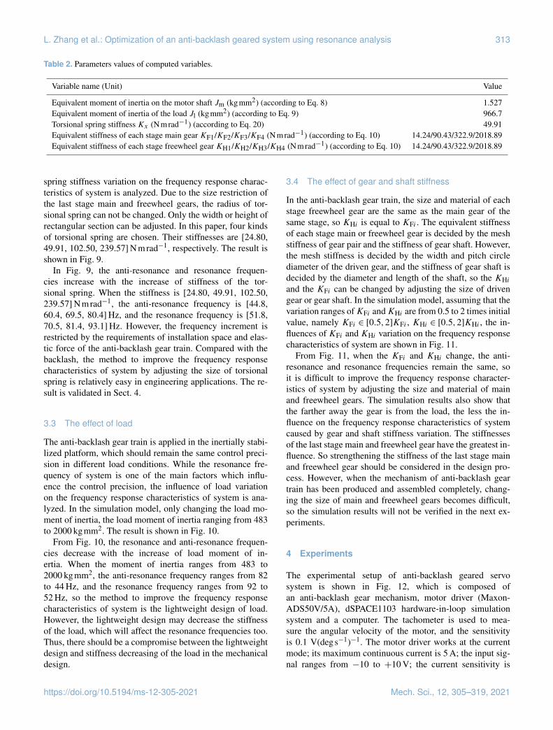
Table 2. Parameters values of computed variables.
Variable name (Unit) Value
Equivalent moment of inertia on the motor shaft Jm (kgmm2) (according to Eq. 8) 1.527Equivalent moment of inertia of the load Jl (kgmm2) (according to Eq. 9) 966.7Torsional spring stiffness Kx (Nmrad−1) (according to Eq. 20) 49.91Equivalent stiffness of each stage main gear KF1/KF2/KF3/KF4 (Nmrad−1) (according to Eq. 10) 14.24/90.43/322.9/2018.89Equivalent stiffness of each stage freewheel gear KH1/KH2/KH3/KH4 (Nmrad−1) (according to Eq. 10) 14.24/90.43/322.9/2018.89
spring stiffness variation on the frequency response charac-teristics of system is analyzed. Due to the size restriction ofthe last stage main and freewheel gears, the radius of tor-sional spring can not be changed. Only the width or height ofrectangular section can be adjusted. In this paper, four kindsof torsional spring are chosen. Their stiffnesses are [24.80,49.91, 102.50, 239.57] Nmrad−1, respectively. The result isshown in Fig. 9.
In Fig. 9, the anti-resonance and resonance frequen-cies increase with the increase of stiffness of the tor-sional spring. When the stiffness is [24.80, 49.91, 102.50,239.57] Nmrad−1, the anti-resonance frequency is [44.8,60.4, 69.5, 80.4] Hz, and the resonance frequency is [51.8,70.5, 81.4, 93.1] Hz. However, the frequency increment isrestricted by the requirements of installation space and elas-tic force of the anti-backlash gear train. Compared with thebacklash, the method to improve the frequency responsecharacteristics of system by adjusting the size of torsionalspring is relatively easy in engineering applications. The re-sult is validated in Sect. 4.
3.3 The effect of load
The anti-backlash gear train is applied in the inertially stabi-lized platform, which should remain the same control preci-sion in different load conditions. While the resonance fre-quency of system is one of the main factors which influ-ence the control precision, the influence of load variationon the frequency response characteristics of system is ana-lyzed. In the simulation model, only changing the load mo-ment of inertia, the load moment of inertia ranging from 483to 2000 kgmm2. The result is shown in Fig. 10.
From Fig. 10, the resonance and anti-resonance frequen-cies decrease with the increase of load moment of in-ertia. When the moment of inertia ranges from 483 to2000 kgmm2, the anti-resonance frequency ranges from 82to 44 Hz, and the resonance frequency ranges from 92 to52 Hz, so the method to improve the frequency responsecharacteristics of system is the lightweight design of load.However, the lightweight design may decrease the stiffnessof the load, which will affect the resonance frequencies too.Thus, there should be a compromise between the lightweightdesign and stiffness decreasing of the load in the mechanicaldesign.
3.4 The effect of gear and shaft stiffness
In the anti-backlash gear train, the size and material of eachstage freewheel gear are the same as the main gear of thesame stage, so KHi is equal to KFi . The equivalent stiffnessof each stage main or freewheel gear is decided by the meshstiffness of gear pair and the stiffness of gear shaft. However,the mesh stiffness is decided by the width and pitch circlediameter of the driven gear, and the stiffness of gear shaft isdecided by the diameter and length of the shaft, so the KHiand the KFi can be changed by adjusting the size of drivengear or gear shaft. In the simulation model, assuming that thevariation ranges ofKFi andKHi are from 0.5 to 2 times initialvalue, namely KFi ∈ [0.5,2]KFi , KHi ∈ [0.5,2]KHi , the in-fluences of KFi and KHi variation on the frequency responsecharacteristics of system are shown in Fig. 11.
From Fig. 11, when the KFi and KHi change, the anti-resonance and resonance frequencies remain the same, soit is difficult to improve the frequency response character-istics of system by adjusting the size and material of mainand freewheel gears. The simulation results also show thatthe farther away the gear is from the load, the less the in-fluence on the frequency response characteristics of systemcaused by gear and shaft stiffness variation. The stiffnessesof the last stage main and freewheel gear have the greatest in-fluence. So strengthening the stiffness of the last stage mainand freewheel gear should be considered in the design pro-cess. However, when the mechanism of anti-backlash geartrain has been produced and assembled completely, chang-ing the size of main and freewheel gears becomes difficult,so the simulation results will not be verified in the next ex-periments.
4 Experiments
The experimental setup of anti-backlash geared servosystem is shown in Fig. 12, which is composed ofan anti-backlash gear mechanism, motor driver (Maxon-ADS50V/5A), dSPACE1103 hardware-in-loop simulationsystem and a computer. The tachometer is used to mea-sure the angular velocity of the motor, and the sensitivityis 0.1 V(degs−1)−1. The motor driver works at the currentmode; its maximum continuous current is 5 A; the input sig-nal ranges from −10 to +10 V; the current sensitivity is
https://doi.org/10.5194/ms-12-305-2021 Mech. Sci., 12, 305–319, 2021

314 L. Zhang et al.: Optimization of an anti-backlash geared system using resonance analysis
Figure 9. Influence of torsional spring stiffness variation on thefrequency response characteristics of system. (a) Bode diagram de-pendent on torsional spring stiffness variation. (b) Anti-resonanceand resonance frequencies dependent on torsional spring stiffnessvariation.
0.8 VA−1. dSPACE1103 provides AD and DA interface; theresolution is 14 bit; the interface modules are embedded inMATLAB/Simulink; the voltage of tachometer can be sam-pled and motor driver control signal can be generated; thebode diagram of output/input can be plotted in MATLAB.The simulation results of Sects. 3.1 and 3.4 will not be veri-fied, because it is not easy to adjust the backlash, gear mesh
Figure 10. Influence of load variation on the frequency responsecharacteristics of system. (a) Bode diagram dependent on load vari-ation. (b) Anti-resonance and resonance frequencies dependent onload variation.
stiffness and gear shaft stiffness. The simulation results ofSects. 3.2 and 3.3 will be verified in this experimental setup.
The initial state of the experimental setup containing themagnitude of backlash is approximately 0.15◦; the stiffnessof torsional spring is 49.91 Nmrad−1; the moment of iner-tia of load is 966.7 kgmm2; the size and material of mainand freewheel gears are designed according to the specificproject. First, the frequency response characteristics of ex-perimental setup are tested in the initial state. The resonance
Mech. Sci., 12, 305–319, 2021 https://doi.org/10.5194/ms-12-305-2021

L. Zhang et al.: Optimization of an anti-backlash geared system using resonance analysis 315
Figure 11. Bode diagrams of anti-backlash geared servo system with the gears and shafts stiffness variation. (a) KF1 and KH1. (b) KF2 andKH2. (c) KF3 and KH3. (d) KF4 and KH4.
and anti-resonance frequencies are obtained from the bodediagram. Then, three kinds of torsional spring are used toreplace the initial one. They have different rectangular sec-tions; the calculated values of stiffness are [24.80, 102.50,239.57] Nmrad−1. The frequency response characteristics ofservo system with these torsional springs are tested, respec-tively. The results are shown in Fig. 13. Finally, the stiffnessof torsional spring remains 49.91 Nmrad−1. Only changingthe moment of inertia of load, three kinds of load are usedto replace the initial one. The moments of inertia values are
[483, 966.7, 2000] kgmm2. The frequency response charac-teristics of them are tested, respectively, and the results areshown in Fig. 14.
From Figs. 13 and 14, the resonance and anti-resonancefrequencies of system increase with the increase of torsionalspring stiffness and decrease with the increase of load mo-ment of inertia. Compared with the experiment results, themaximum error of simulation results is less than 10 Hz,which is shown in Table 3. These results show that the modelof anti-backlash geared servo system is reasonable; the sim-
https://doi.org/10.5194/ms-12-305-2021 Mech. Sci., 12, 305–319, 2021

316 L. Zhang et al.: Optimization of an anti-backlash geared system using resonance analysis
Figure 12. Experimental setup of the anti-backlash geared servo system: (1) dSPACE1103, (2) motor driver, (3) motor, (4) tachometer and(5) anti-backlash gear train, six-load.
Table 3. Comparative analysis between the simulation and experiment results.
Torsional spring stiffnessKx (Nmrad−1) Simulation Experiment
ARF(Hz) RF(Hz) ARF(Hz) RF(Hz)
24.8 44.8 51.8 43.7 55.449.91 60.4 70.5 62.3 78.9102.5 69.5 81.4 70.1 88.8
239.57 80.4 93.1 76.8 93.5
Load moment of inertiaJl (kgmm2) Simulation Experiment
ARF(Hz) RF(Hz) ARF(Hz) RF(Hz)
483 81.4 91.1 79.0 89.8966.7 59.4 72.3 62.3 78.92000 44.2 52.5 42.9 56.9
ulation results of Sects. 3.2 and 3.3 are correct, and the sim-ulation results of Sects. 3.1 and 3.4 are a credible prediction.The errors of simulation analysis are caused by the modelparameter difference compared with the experimental setupsystem. When the mechanism of anti-backlash gear train isassembled, the parameters of model can be obtained throughthe experiment identification, and then the experiment resultsmay stay more consistent with simulation results.
5 Conclusion
The total backlash, torsional spring stiffness and load mo-ment of inertia are the main factors that influence the fre-quency response characteristics of the anti-backlash gearedservo system. The resonance and anti-resonance frequenciesincrease with the decrease of the total backlash and the load
Mech. Sci., 12, 305–319, 2021 https://doi.org/10.5194/ms-12-305-2021

L. Zhang et al.: Optimization of an anti-backlash geared system using resonance analysis 317
Figure 13. Bode diagram of the experimental setup with differenttorsional spring stiffnesses.
moment of inertia and increase with the increase of the tor-sional spring stiffness.
The simulation results show that when the total backlashranges from 0.01 to 0.5◦, the anti-resonance frequency rangesfrom 170 to 60 Hz, and the resonance frequency rangesfrom 190 to 70 Hz; when the stiffness of torsional spring is[24.80, 49.91, 102.50, 239.57] Nmrad−1, the anti-resonancefrequency is [44.8, 60.4, 69.5, 80.4] Hz, and the resonancefrequency is [51.8, 70.5, 81.4, 93.1] Hz; when the load mo-ment of inertia ranges from 483 to 2000 kgmm2, the anti-resonance frequency ranges from 82 to 44 Hz, and the res-onance frequency ranges from 92 to 52 Hz; when the varia-tion ranges of gear mesh stiffness and gear shaft stiffness arefrom 0.5 to 2 times initial value, the anti-resonance and res-onance frequencies remain the same. The experiment resultsshow that the maximum error of simulation results is lessthan 10 Hz. The model of anti-backlash geared servo systemis reasonable. The simulation results of Sects. 3.2 and 3.3 arecorrect, and the simulation results of Sects. 3.1 and 3.4 are acredible prediction.
From the mechanical parameter point of view, increasingthe stiffness of torsional spring can improve the frequencyresponse characteristics of system. This target is easy to real-ize by changing the width or height parameters of rectangularsection of the torsional spring. Reducing the total backlashof anti-backlash gear train is another method of system im-provement. The magnitude of backlash is influenced by the
Figure 14. Bode diagram of the experimental setup with differentloads.
manufacture and assembly technology. From the mechanicaldesign aspect, designing the center distance adjusting mech-anism can decrease the initial total backlash, and the loadlightweight design can also improve the frequency responsecharacteristics of system, but the stiffness of the load shouldbe considered simultaneously. These measures will be ap-plied in our future work.
Data availability. All data generated or analyzed during this studyare included in this published article.
Author contributions. LZ and HL designed the methodology,created the model, simulated the model and designed the experi-mental setup of servo system. DF provided the ideas, financial sup-port and supervised the research activity planning and execution. SFdesigned the experimental software and collected the experimentaldata. JZ designed the mechanical structure of anti-backlash gearedsetup and the arc springs. LZ designed the experiments and carriedthem out. LZ and HL prepared the manuscript with contributionsfrom all co-authors.
Competing interests. The authors declare that they have no con-flict of interest.
https://doi.org/10.5194/ms-12-305-2021 Mech. Sci., 12, 305–319, 2021

318 L. Zhang et al.: Optimization of an anti-backlash geared system using resonance analysis
Acknowledgements. The authors would like to express theirthanks to the supporting agencies.
Financial support. This research has been supported by the Na-tional Key R&D Program of China (grant no. 2019YFB2004700)and the Preliminary Research Project of National University of De-fense Technology (grant no. ZN2019-7).
Review statement. This paper was edited by Dario Richiedei andreviewed by two anonymous referees.
References
Allan, P. M. and Levy, N. M.: The determination of min-imum pre-load torque for antibacklash gears in a posi-tional servomechanism, IEEE Trans. Ind. Electron., 27, 26–29,https://doi.org/10.1109/TIECI.1980.351657, 1980.
Asada, H., Youcef-Toumi, K., and Koren, Y.: Direct-Drive robots,theory and practice, J. Dyn. Syst. Meas. Control, 111, 119–120,https://doi.org/10.1115/1.3153012, 1989.
Baek, J. H., Kwak, Y. K., and Kim, S. H.: Backlash estima-tion of a seeker gimbal with two-stage gear reducers, J. Adv.Manuf. Technol., 21, 604–611, https://doi.org/10.1007/s00170-002-1378-z, 2003a.
Baek, J. H., Kwak, Y. K., and Kim, S. H.: Analysis on the influ-ence of backlash and motor input voltage in geared servo sys-tem, 11th IEEE Mediterr. Conf. Control and Automat., Rhodes,Greece, 18–20 June 2003, T1-010, 2003b.
Bahn, W., Kima, T. I., Li, S. H., and Cho, D. I.: Res-onant frequency estimation for adaptive notch filtersin industrial servo systems, Mechatronics, 41, 45–57,https://doi.org/10.1016/j.mechatronics.2016.11.004, 2016.
Chung, J. W., Park, I. W., and Oh, J. H.: On the design and develop-ment of a quadruped robot platform, Adv. Robot., 24, 277–298,https://doi.org/10.1163/016918609X12586214966992, 2010.
Dwivedula, R. V. and Pagilla, P. R.: Effect of Complianceand Backlash on the Output Speed of a Mechanical Trans-mission System, J. Dyn. Syst. Meas. Control, 134, 031010,https://doi.org/10.1115/1.4005493, 2012.
George, E. and Gao, Z. Q.: Cures for low-frequency mechanicalresonance in industrial servo systems, IEEE 36th IAS Annu.Meet.Chicago, USA, 30 September–4 October 2001, 252–258,https://doi.org/10.1109/IAS.2001.955419, 2001.
George, W. Y.: Compensating structural dynamics for Servo DrivenIndustrial Machines with acceleration feedback, IEEE 39th IASAnnu. Meet., Seattle, USA, 3–7 October 2004, 50p4, 1881–1890,https://doi.org/10.1109/IAS.2004.1348726, 2004.
Hale, L. C. and Slocum, A. H.: Design of anti-backlash transmis-sions for precision position control systems, Precis. Eng., 16,244–258, https://doi.org/10.1016/0141-6359(94)90001-9, 1994.
Hilkert, J. M.: Inertially stabilized platform tech-nology, IEEE Control Syst. Mag., 28, 26–46,https://doi.org/10.1109/MCS.2007.910256, 2008.
Hoogendijk, R., Heertjes, M. F., van de Molengraft, M. J.G., and Steinbuch, M.: Directional notch filters for mo-
tion control of flexible structures, Mechatronics, 24, 632–639,https://doi.org/10.1016/j.mechatronics.2014.01.011, 2014.
Jesper, B.: Transmission error in anti-backlash conical involute geartransmissions, a global–local FE approach, Finite Elem. Anal.Des., 41, 431–457, https://doi.org/10.1016/j.finel.2004.04.007,2004.
Jia, S. X., Howard, I., and Wang, J. D.: The Dynamic Model-ing of Multiple Pairs of Spur Gears in Mesh, Including Fric-tion and Geometrical Errors, Int. J. Rotating Mach., 9, 437–442,https://doi.org/10.1080/10236210390241592, 2003.
Kolnik, I. and Agranovich, G.: Backlash compensation for motionsystem with elastic transmission, 2012 IEEE 27th Conv. Elect.and Elect. Eng., Eilat, Israel, 14–17 November 2012, 1–5, IEEE,https://doi.org/10.1109/EEEI.2012.6377140, 2012.
Kwon, Y. S., Hwang, H. Y., Lee, H. R., and Kim, S. H.: Rate loopcontrol based on torque compensation in Anti-backlash gearedservo system. Proc. 2004 Am. Control Conf., Boston, USA, 30June–2 July 2004, ThP03.3, Piscataway, NJ, USA, IEEE, 3327–3332, https://doi.org/10.23919/ACC.2004.1384422, 2004.
Lee, D. H., Lee, J. H., and Ahn, J. W.: Mechanical vibration reduc-tion control of two-mass permanent magnet synchronous motorusing adaptive notch filter with fast Fourier transform analysis,IET Electr. Power Appl., 6, 455–461, https://doi.org/10.1049/iet-epa.2011.0322, 2012.
Li, Z. F., Zhu, C. C., Liu, H. J, and Gu, Z. L.: Mesh stiffnessand nonlinear dynamic response of a spur gear pair consider-ing tribo-dynamic effect, Mech. Mach. Theory, 153, 103989,https://doi.org/10.1016/j.mechmachtheory.2020.103989, 2020.
Masoumi, M. and Alimohammadi, H.: An investigation into the vi-bration of harmonic drive systems, Front. Mech. Eng., 8, 409–419, https://doi.org/10.1007/s11465-013-0275-5, 2013.
Nordin, M., and Gutman, P. O.: Controlling mechanical sys-tems with backlash-a survey, Automatica, 38, 1633–1649,https://doi.org/10.1016/S0005-1098(02)00047-X, 2002.
Shi, H. and Yang, X. H.: Spring’s elastic force com-putation for double gear, Radar ECM, 3, 45–50,https://doi.org/10.19341/j.cnki.issn.1009-0401.2000.03.009,2000 (in Chinese).
Shi, J. F, Gou, X. F., and Zhu, L. Y.: Calcula-tion of time-varying backlash for an involute spurgear pair, Mech. Mach. Theory, 152, 103956,https://doi.org/10.1016/j.mechmachtheory.2020.103956, 2020.
Shim, S. B., Park, Y. J., and Kim, K. U.: Reductionof PTO rattle noise of an agricultural tractor usingan anti-backlash gear, Biosyst. Eng., 100, 346–354,https://doi.org/10.1016/j.biosystemseng.2008.04.002, 2008.
Slamani, M. and Bonev, I. A.: Characterization and experimen-tal evaluation of gear transmission errors in an industrial robot,Ind. Rob., 40, 441–449, https://doi.org/10.1108/IR-07-2012-387,2013.
Su, Y. X., Duan, B. Y., and Zheng, C. H.: Mechatronics de-sign of stiffness enhancement for direct-drive motor sys-tem using ER variable damper, J. Robot. Syst., 19,419–425,https://doi.org/10.1002/rob.10050, 2002.
Szabat, K. and Orlowska-Kowalska, T.: Vibration suppression ina two-mass drive system using PT speed controller and addi-tional feedbacks comparative study, IEEE Trans. Ind. Electron.,54, 1193–1206, https://doi.org/10.1109/TIE.2007.892608, 2007.
Mech. Sci., 12, 305–319, 2021 https://doi.org/10.5194/ms-12-305-2021
L. Zhang et al.: Optimization of an anti-backlash geared system using resonance analysis 319
Vassileva, D., Kiyosawa, Y., and Suzuki, M.: SensorlessTorque control for a robot with harmonic drive re-ducers, Mech. Based Des. Struct. Mach., 39, 253–267,https://doi.org/10.1080/15397734.2011.550859, 2011.
Walha, L., Fakhfakh, T., and Haddar, M.: Nonlinear dynamics ofa two-stage gear system with mesh stiffness fluctuation, bearingflexibility and backlash, Mech. Mach. Theory, 44, 1058–1069,https://doi.org/10.1016/j.mechmachtheory.2008.05.008, 2009.
Wang, J., Qin, D., and Lim, T. C.: Influence of combined assem-bly error and bearing elasticity on spur gear tooth contact loaddistribution, Proc. Inst. Mech. Eng. C J. Mech. Eng. Sci., 225,1507–1521, https://doi.org/10.1177/0954406211399212, 2011.
Wang, J. H., Wang, J., and Lim, T. C.: Influence of assembly er-ror and bearing elasticity on the dynamics of spur gear pair,Proc. Inst. Mech. Eng. C J. Mech. Eng. Sci., 230, 1805–1818,https://doi.org/10.1177/0954406215584632, 2016.
Yang, M., Wang, C., Xu, D. G., Zheng, W. L., and Lang,X. Y.: Shaft Torque Limiting Control Using Shaft TorqueCompensator for Two-Inertia Elastic System With Back-lash, IEEE ASME Trans. Mechatron., 21, 2902–2911,https://doi.org/10.1109/TMECH.2016.2571304, 2016.
Yang, Z., Shang, J. Z., and Luo, Z. R.: Effect analysis of frictionand damping on anti-backlash gear based on dynamics modelwith time-varying mesh stiffness, J. Cent. South Univ., 20, 3461–3470, https://doi.org/10.1007/s11771-013-1870-7, 2013.
Zhou, J. Z., Duan, B. Y., and Huang, J.: Modeling and effectson open-loop frequency for servo system with backlash, Chin.Mech. Eng., 20, 1722–1725, 2009 (in Chinese).
https://doi.org/10.5194/ms-12-305-2021 Mech. Sci., 12, 305–319, 2021