


DESIGN OF UNDERGROUND ELEMENTS FOR THE RAW WATER INTAKE ... · design of underground elements for...
59
DESIGN OF UNDERGROUND ELEMENTS FOR THE RAW WATER INTAKE FACILITIES CITY OF AUSTIN WATER TREATMENT PLANT NO. 4 Gregg Sherry – Brierley Associates, LLC Shelby Eckols - AECOM William Stauber – City of Austin, TX
Transcript of DESIGN OF UNDERGROUND ELEMENTS FOR THE RAW WATER INTAKE ... · design of underground elements for...

DESIGN OF UNDERGROUND ELEMENTS FOR THE RAW WATER INTAKE
FACILITIES CITY OF AUSTIN WATER TREATMENT PLANT
NO. 4
Gregg Sherry – Brierley Associates, LLC Shelby Eckols - AECOM
William Stauber – City of Austin, TX

Project Background
Planning began in 1980’s Original design 1984 to 1986 60 MGD Treatment Plant Three separate intakes (550, 605 & 640 MSL) Tunnel - 11,000 ft , 10 ft dia Pump station at Water Treatment Plant
Bid in 1986 then paced on hold

Project Background
City of Austin retains Carollo in 2002 to design current WTP # 4 project AECOM lead designer for Raw water Intake
Facilities Brierley Associates lead designer for underground
facilities
Project Location

Hydraulic Profile – Raw Water Facilities
Tunnel & Intake– 300 MGD
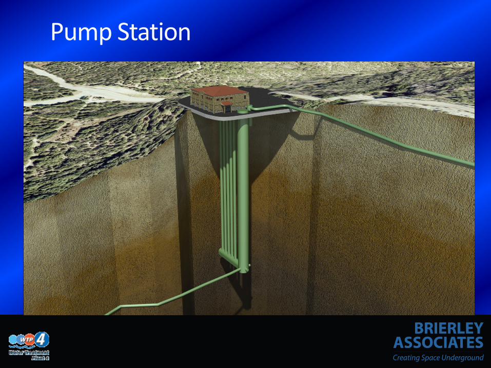
Pump Station - 50 MGD
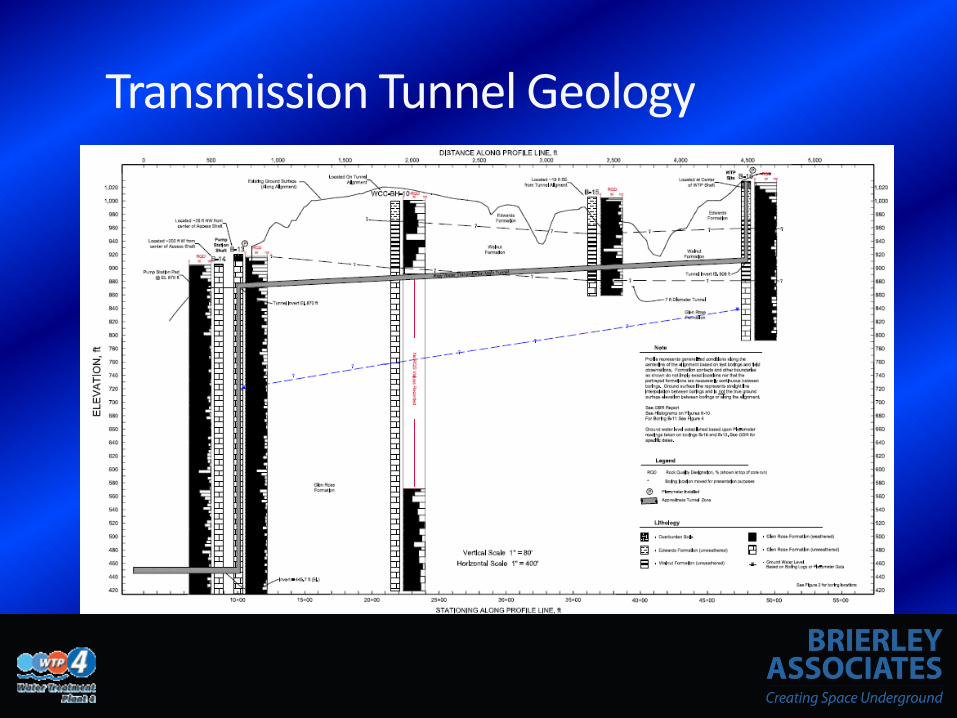
Transmission Tunnel - 150 MGD

Geotechnical investigations “Geotechnical Report, Raw Water Intake
Facilities, Water Treatment Plant No. 4, Austin, Texas”, Revision One, Volumes 1 & 2, prepared by Woodward-Clyde Consultants for Lake Travis Consultants, May, 1986.
“Geotechnical Data Report, City of Austin, Water
Treatment Plant No. 4, Raw Water Facilities and Tunnels, Austin, Texas,” prepared by Fugro Consultants, Inc., for TCB, February 2010.

Geology
Transition between Walnut and Glen Rose
Walnut Formation
Glen Rose Formation

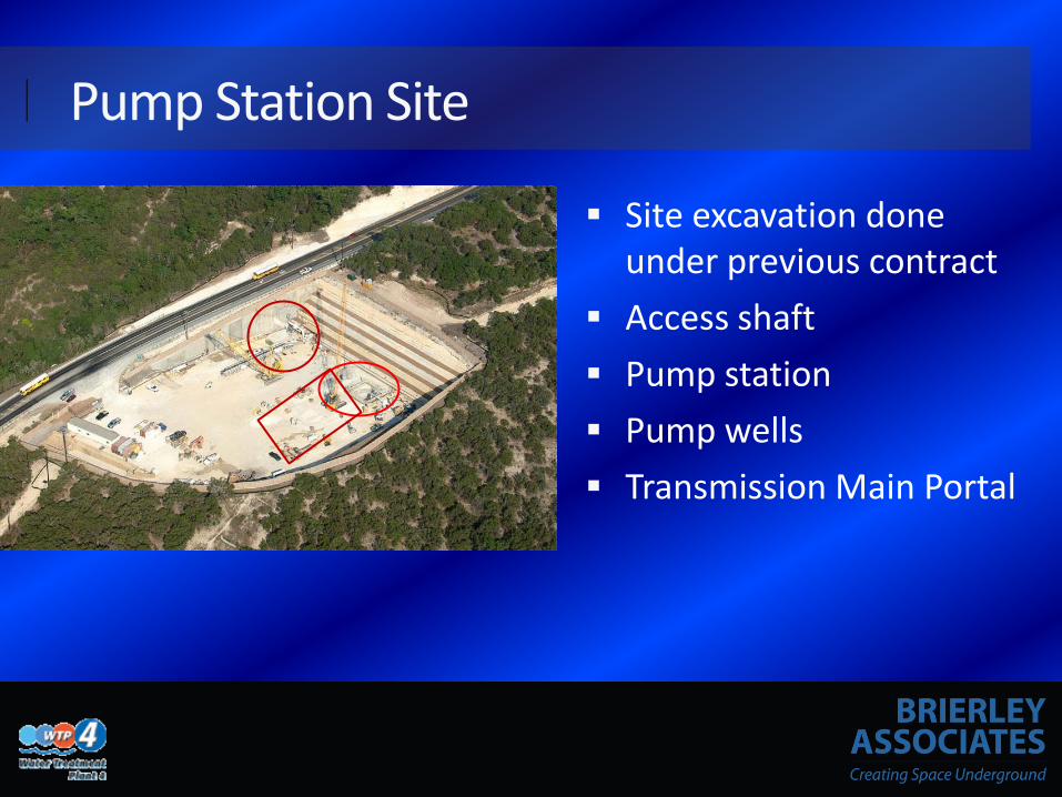
Pump Station Site
Site Excavation Performed on Previous Contract
Pump Station Site
Site excavation done under previous contract
Access shaft Pump station Pump wells Transmission Main Portal

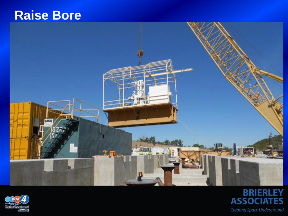
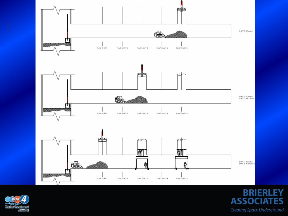
Raise Bore • Robbins 7-SP Drilling
Machine
• 250hp DC Motor
• Breakout Torque of 252,000 Ft-lbs.
• Hydraulic Reaming Thrust of 800,000 Lbs.

Access Shaft
Located at pump station site 25.5 ft dia. Elev. 870 to 445 msl (425 ft) Suction cavity – 12.5 by 12.5 ft
horseshoe. Pump suction wells – 60 dia. inch steel Future tunnel connection – 9 ft by 9 ft
horseshoe excavation Intake tunnel connection

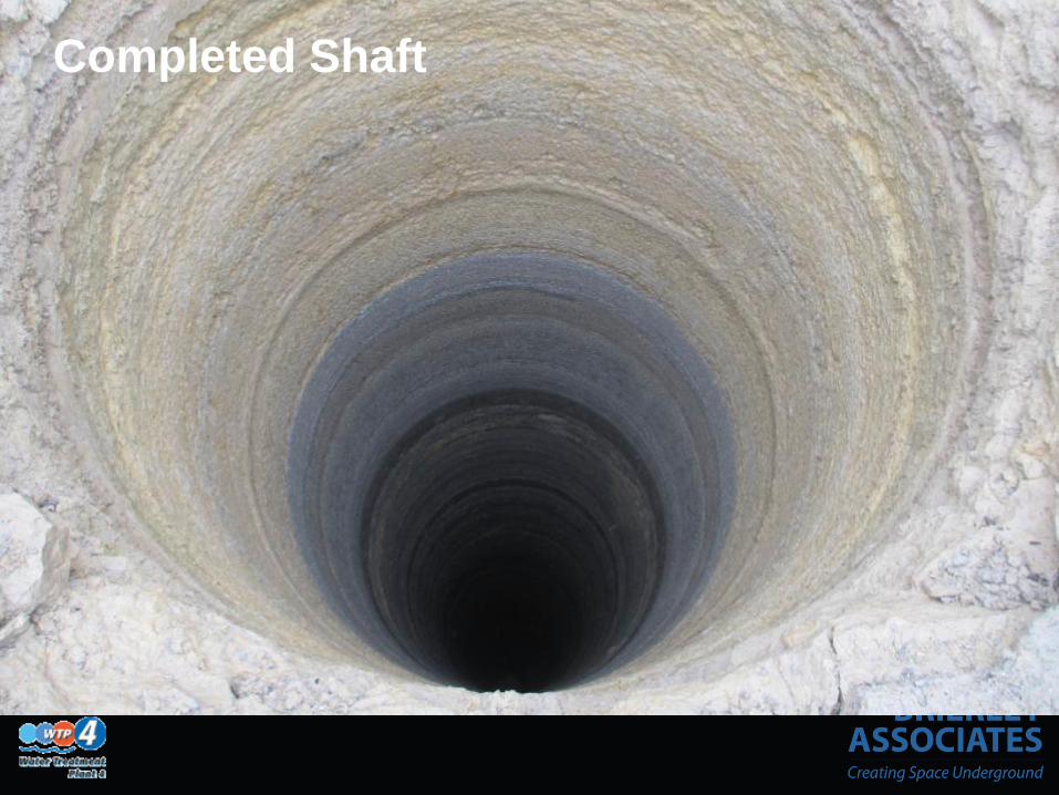
Access Shaft Construction
Confined Construction site Roadheader - 28.5 ft
excavated Cast-in-Place Lining - change
order (shotcrete & bolts originally)

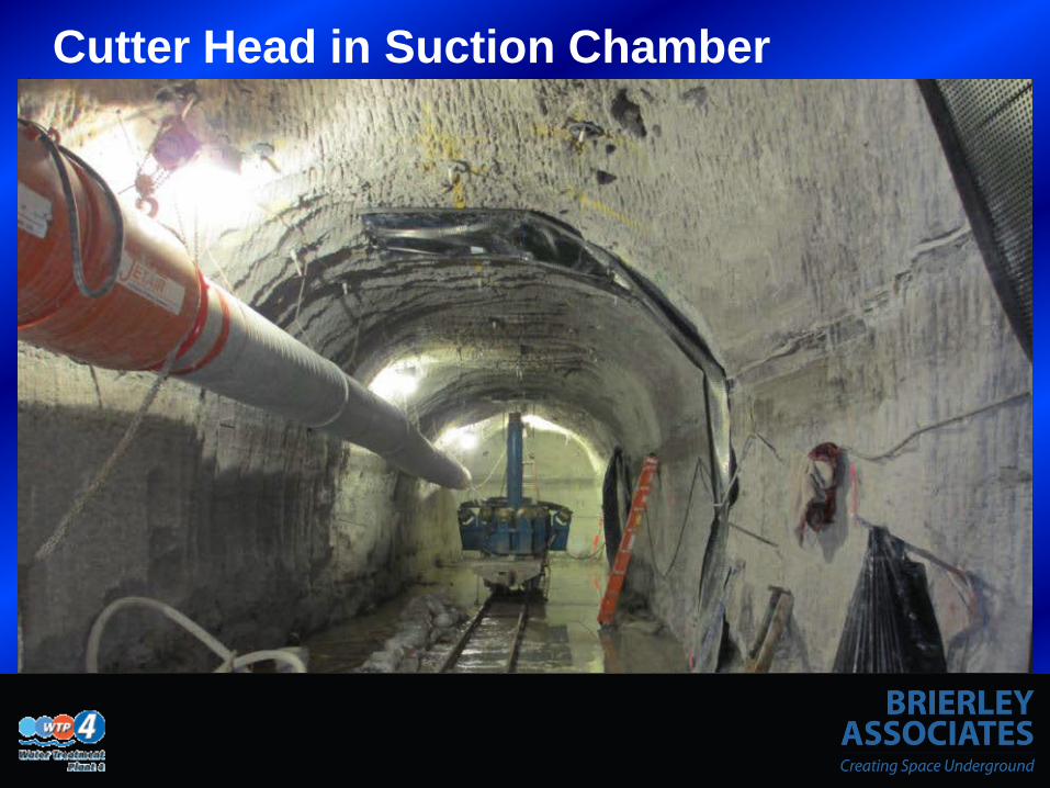
Suction Cavity
12.5 by 12.5 horseshoe excavation by Roadheader Concrete lining Suction well shaft connections

Future tunnel connection 9 ft x 9 ft horseshoe
excavation by Roadheader Steel lined Bulkhead for future
connection

Intake tunnel
Access Shaft to Intake Riser - 4386 ft Probe holes Initial support two bolts typical Weak ground - shotcrete, 4 bolts and mesh 9 ft diameter Cast-in-place concrete lining

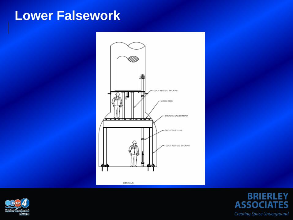
Connection to Intake shaft Shaft done before tunnel
excavation is within 60 ft Mandatory probing and
grouting Excavation proceeds to
shaft riser pipe Constructed a steel tee
connection. Construct a reinforced
concrete transition section Begin unreinforced
concrete lining

Intake Marine construction in
approximately 150 ft of water
Three intakes at 652, 607 and 568 msl
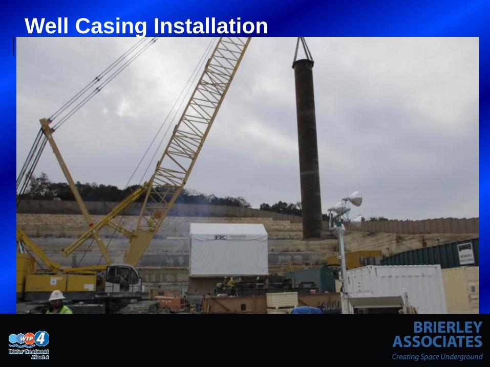
Riser shaft, 9 ft diameter steel pipe, grouted annulus
Caisson foundations (subject to value engineering)

Transmission Main Tunnel
Portal at Pump Station Site 3873 ft long, 7 ft diameter Initial support two bolts typical Weak ground - shotcrete, 4 bolts and mesh 7 ft dia. Steel lining backfilled with cellular grout Blind bore shaft with 7 ft dia. riser at Treatment Plan Site

Transmission Main Tunnel
Roadheader excavation Portal in South wall of Pump Station Site

Construction
Construction Management At Risk – MWH Subcontractor for Underground and Marine
work – Hill Country Constructors (Obayashi & Manson)
Began in Spring 2011 Finished Summer 2014