Design of structures for earthquake resistance Design of structures for earthquake resistance...
14
1
Transcript of Design of structures for earthquake resistance Design of structures for earthquake resistance...
1
2
Design of structures for earthquake resistance
According to Eurocode 8: Design of structures for earthquake resistance - Part 1:
General rules, seismic actions and rules for buildings
ANNEX to
1. Guidelines for calculating and constructing walls in the IZODOM 2000 POLSKA SYSTEM
2. Guidelines for calculating and constructing ceilings in the IZODOM 2000 POLSKA SYSTEM
Authors:
prof. dr hab. ing. Maria Kamińska
ing. dipl. Ewelina Kołodziejczyk
October2012
Łódź, Poland
Izodom 2000 Polska Spółka z o.o.
98-220 Zduńska Wola, ul. Ceramiczna 2a
tel. 043 823 23 68, fax. 043 823 41 88
e-mail: [email protected]
www.izodom.pl
3
Contenu
General Information ............................................................................................................................... 4
I. Conditions for the structure layout design .......................................................................................... 4
II. Requirements with regard to materials ............................................................................................. 5
III. Requirements for walls ..................................................................................................................... 5
IV. Requirements for ceilings ................................................................................................................. 7
V. Requirements for tie beams and lintels ........................................................................................... 10
VI. Requirements for foundations ........................................................................................................ 11
Table W1 ............................................................................................................................................... 12
Table W2 ............................................................................................................................................... 13
Related standards
[C1] PN-EN 1990:2004 Eurocode 0: Basis of structural design
[C2] PN-EN 1991-1-1:2004 Eurocode 1: Actions on structures - Part 1-1 : General actions -
Densities, self-weight, imposed loads for buildings
[C3] PN-EN 1992-1-1:2008 Eurocode 2: Design of concrete structures - Part 1-1: General rules and
rules for buildings
[C4] PN-EN 1992-1-2:2008 Eurocode 2: Design of concrete structures - Part 1-2: General rules –
Structural fire design
[C5] EN 1998-1:2004 Eurocode 8: Design of structures for earthquake resistance - Part 1:
General rules, seismic actions and rules for buildings
4
General Information
In seismic areas the risk of seismic load should be taken into consideration already at the stage of
developing the concept for a building, allowing one to design a structural system which, at an
acceptable cost, meets basic requirements as contained in 2.1 PN-EN 1998-1-1.
In developing a building’s structural concept one should keep in mind the following:
− simplicity of the structural design;
− the uniformity, symmetry and hyperstatics (stiffening) of the whole system;
− two-directional strength and rigidity;
− torsional strength and rigidity;
− the work of ceilings as a skirt;
− appropriate foundations.
The IZODOM system makes it easy to meet all the above conditions. The walls and ceilings
of reinforced concrete form a rigid three-dimensional spatial arrangement, capable of transferring
seismic loads.
Buildings made of concrete are designed in accordance with PN-EN 1992-1-1:2004. The following
rules should be seen as complementary to the general rules contained in the standard PN-EN 1992-
1-1:2004 and documents [1] and [2].
I. Conditions for the structure layout design
Shaping the structure of the building one must take into account lateral rigidity and weight distribution.
The design should be approximately symmetrical in respect of the two orthogonal axes of the
coordinates system.
The layout design should be compact; the outline of the storeys should form a convex polygon. This
condition may be considered met even in the event of a withdrawal of the elevation line (e.g., concave
corners or recesses), if these indentations do not affect the rigidity of the floor plan or the area of any
of them (calculated to the contracted convex line limiting the contour of the building) and does not
exceed 5% of the storey’s surface area.
The slenderness of the building in plan λ = Lmax/Lmin should not exceed the value of 4 where Lmax and
Lmin are respectively a larger and smaller dimension of the building in plan, measured along the
perpendicular axes.
In each level of the building, in an analysis in both x and y directions, the value of structural eccentricity
eo and torsional radius r must satisfy two conditions, that for an analysis in the plane y may be defined
as:
eox ≤ 0.30 rx
rx ≥ ls
where:
- eox is the distance between the centre of rigidity and the centre of gravity, measured along
direction x, normal for the analysed direction y;
- rx is the square root of the quotient of torsional rigidity and transverse rigidity in direction
y (torsional radius);
5
- ls is the radius of rotation of the ceiling mass as projected (the square root of the quotient of the
polar moment of inertia of the ceiling mass as projected with respect to the centre of gravity of
the floor mass, and the weight of the ceilings).
In single-storey buildings, the centre of rigidity can be defined as the centre of transverse rigidity of all
the elements involved in the transfer of seismic loads. However, the torsional radius r is defined as the
square root of the ratio of global torsional rigidity relative to the centre of transverse rigidity to the
global transverse rigidity in one direction, taking into account all seismic load bearing elements in
a given direction.
Definitions of the centre of rigidity and torsional radius can only be approximated in multi-storey
buildings. These simplified values, serving to classify the regularity of the construction’s layouts and
an approximate analysis of their behaviour in torsion, can be defined when meeting two conditions:
a) all systems transversely bracing the structure, such as cores, walls or frames run without
interruption from the foundations to the top of the building;
b) individual bracing elements have a similar form of deformation under a transverse load. This
condition may be considered met in the case of framework and wall systems. In general, this condition is
not met by mixed systems.
In case of frames and slender walls, dominated by flexural deformations, the position of the centre of
rigidity and torsional radius of all storeys can be calculated as for the moments of inertia of the
transverse cross sections of vertical elements. If in addition to flexural deformation there is a significant
degree of deformation by shearing, these values can be determined by introducing the equivalent
moment of inertia of the cross-section.
II. Requirements with regard to materials
It is permitted to use Class B or C ribbed steel in accordance with the standard EN 1992-1-1:2004
[C3], Table C.1 and C.2N. This applies to vertical and horizontal longitudinal rods, as well as loops and
stirrups.
Reinforcement in the form of bonded reinforcement meshes can also be used where the conditions
described above are met.
In all structural elements class C20/25 to C40/50 concrete should be used.
III. Requirements for walls
All walls should be designed as reinforced concrete walls.
The vertical reinforcement required should be taken into account in calculating the load-bearing
strength of walls due to bending and slenderness. For this one can use the nomographs quoted in [1],
developed for walls with various transverse cross-sections, degrees of longitudinal reinforcement and
slenderness, with axial force loads and a bending moment.
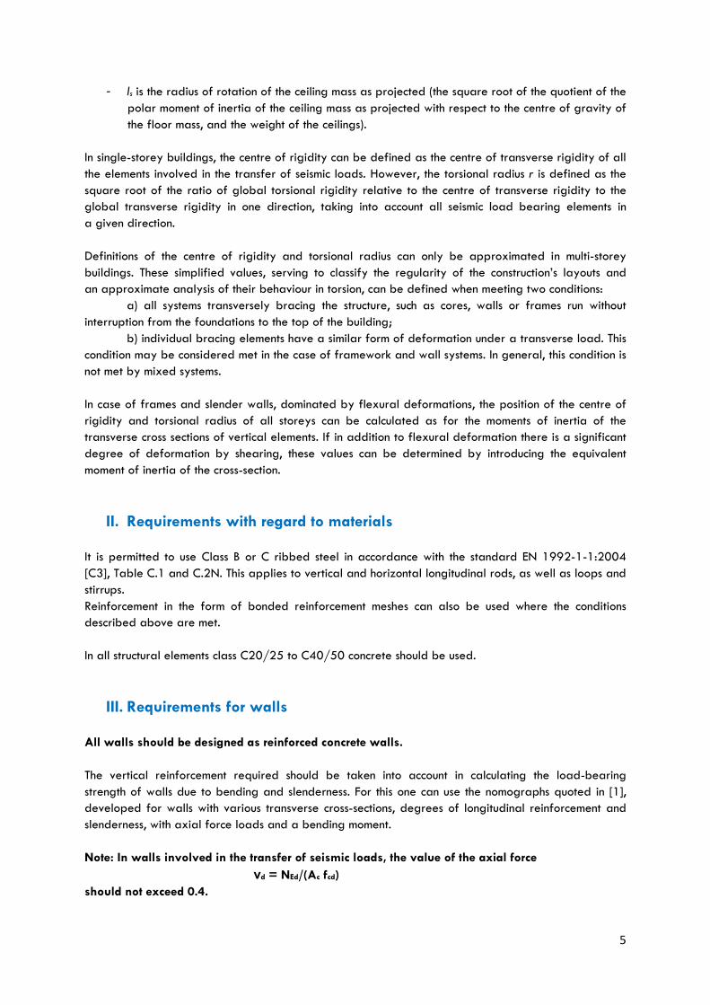
Note: In walls involved in the transfer of seismic loads, the value of the axial force
νd = NEd/(Ac fcd)
should not exceed 0.4.
6
Vertical reinforcement should be connected at both wall surfaces by means of horizontal rods with
a minimum diameter of #8 mm, arranged in each layer of hollow blocks (every 250mm). The two
subsurface reinforcement meshes thus created should be joined using # 8mm diameter fasteners, using
a minimum of 4 to every 1m2 of wall surface. In the corners of walls and at the edges of apertures in
walls, horizontal rods should be shaped in the form of open stirrups in the shape of the letter "U" (see
Fig. K1 and K4 [1]).
With the assumption of a partial anchoring of ceilings in walls, wall reinforcement in the ceiling support
area is to be used according to Fig. K9 [1].
Single channels may be made in the wall, but only around a single wall core and provided continuity
of the horizontal reinforcement is maintained (Fig. K12 [1]). At the edges of apertures, one should place
in the extreme wall cores adjoining them at least two #10mm rods, connected to each other by means
of # 8mm stirrups in each layer of blocks.
Adequate susceptibility to curvature should be ensured in critical areas of walls.
Strengthening (constraint) should be introduced in the vertical at the height of the critical area hcr and
in the horizontal cross-section at length lc.
The height of the critical area hcr, calculated from the base of the wall, can be estimated as:
hcr = max [lw; hw/6]
but
hcr ≤ 2lw
hcr ≤ hs for n ≤ 6 of the storey
where
- lw is the length of the wall;
- hs is the clear height of the storey, where the base of the wall may be taken as the level of the
foundation or the basement storey, as long as this has a rigid floor and perimeter walls;
- hw is the height of the beam.
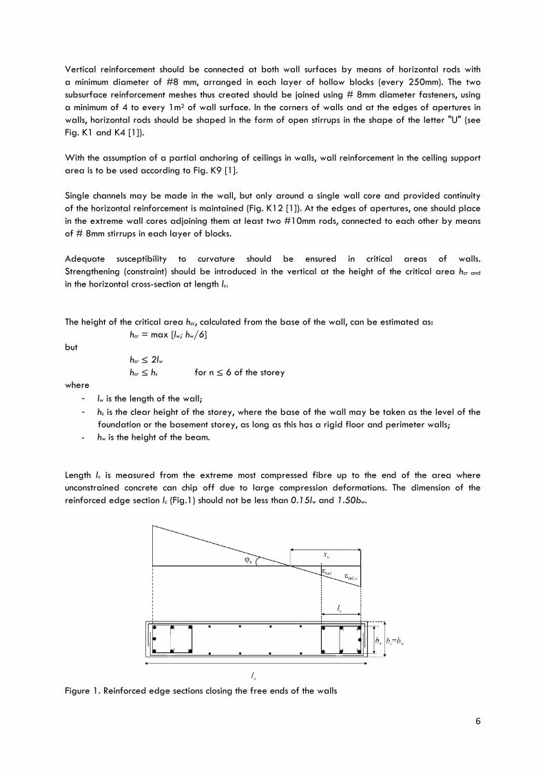
Length lc is measured from the extreme most compressed fibre up to the end of the area where
unconstrained concrete can chip off due to large compression deformations. The dimension of the
reinforced edge section lc (Fig.1) should not be less than 0.15lw and 1.50bw.
Figure 1. Reinforced edge sections closing the free ends of the walls
7
(top: deformation and curvature limit, bottom: cross-section of the wall) [EN 1998-1 [C5])
The degree of longitudinal reinforcement of the cross-section of the edge sections should not be less
than 0.005.
The reinforcement required and permissible axial force are given in Table 1
Table 1 Reinforcement required and the permissible axial force in the edge area of the wall’s cross-section
Nominal wall thickness
bw [m]
Minimum As
mm2/m
Minimum length lc
as 1.5 bw
mm
The axial force should not exceed: [kN/m]
C20/25 C30/37 C40/50
0.15 750 225 746 1120 1493
0.20 1000 300 1013 1520 2026
0.40 2000 600 2080 3120 4160
Horizontal and vertical reinforcement (tie beams) should be introduced continuously through all the
walls, connections with perpendicular walls and around apertures in the wall. Reinforcement should at
least satisfy the conditions contained in standard PN-EN 1992-1-1 [C3], section 9.10 Tying systems.
Closed stirrups should be used in these areas. Each of the longitudinal rods should be caught up by the
corner of the stirrup or by using additional connection clips (Fig. 1).
The spacing between stirrups s (in millimetres) should not exceed:
s = min {b0/2; 175; 8dbL}
where
- b0 is the smallest dimension of the concrete core, calculated to the central line of the stirrups,
- dbL is the smallest diameter of the longitudinal rods.
The distance between successive longitudinal rods held in place by the stirrups or additional connectors
should not exceed 200 mm, in accordance with the requirements [C3].
IV. Requirements for ceilings
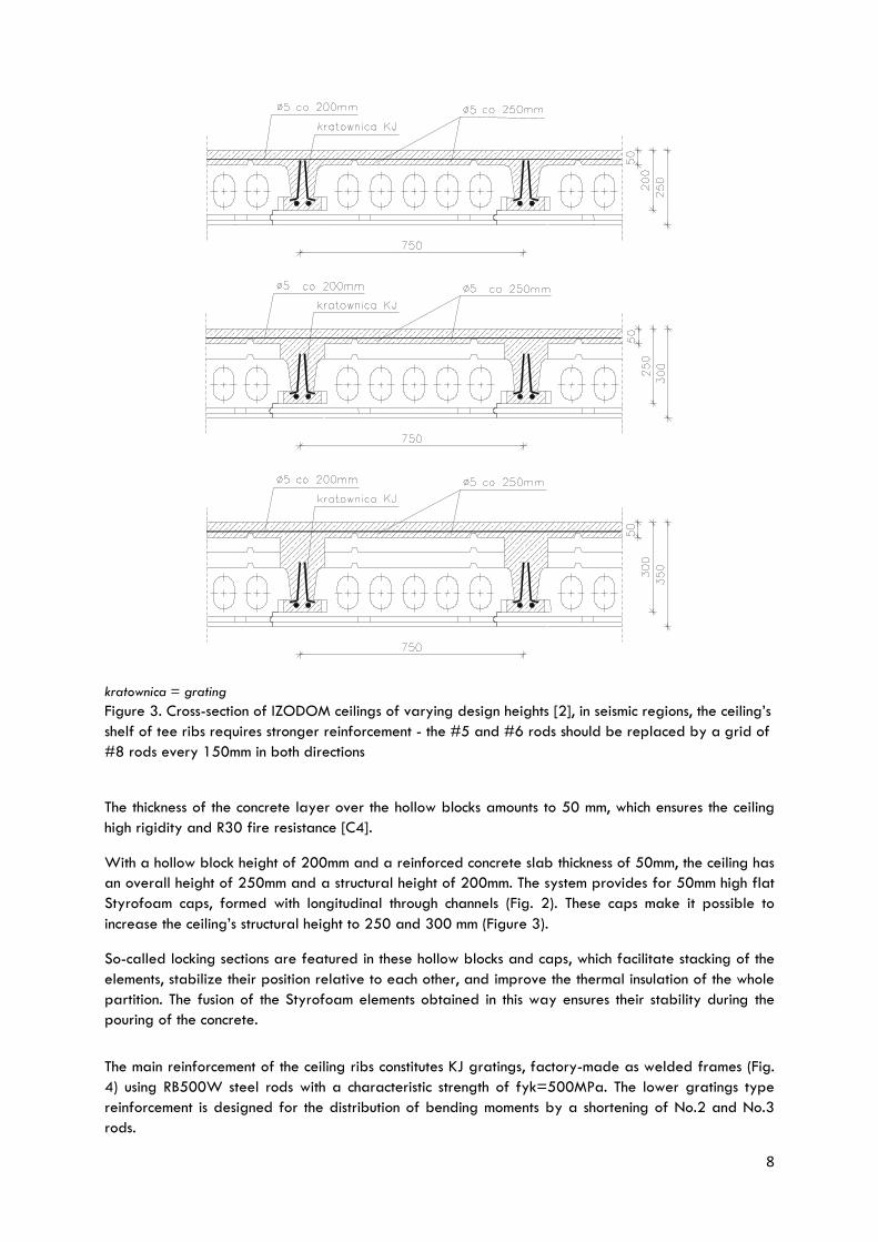
Ceilings in the IZODOM 2000 POLSKA system have been designed as monolithic, densely-ribbed units.
Ceilings are filled with Styrofoam hollow blocks (Fig. 2), designed for rib spacing equal to 0.75 m
Figure 2. Ceiling type hollow block and cap in the IZODOM 2000 POLSKA system [2]
Thanks to this configuration of hollow blocks, very good thermal insulation of the ceiling is obtained. This
is important when building ceilings above an unheated basement or beneath a periodically unused attic
– in such a case the ceiling does not need an extra layer of insulation.
8
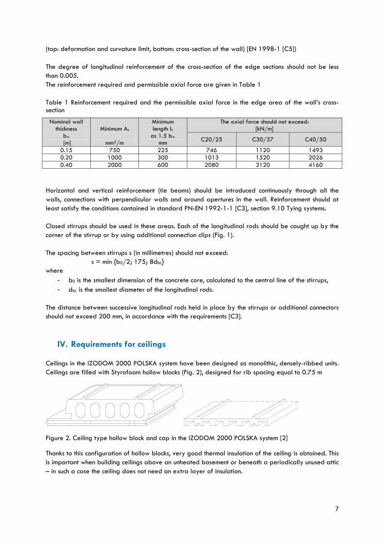
kratownica = grating
Figure 3. Cross-section of IZODOM ceilings of varying design heights [2], in seismic regions, the ceiling’s
shelf of tee ribs requires stronger reinforcement - the #5 and #6 rods should be replaced by a grid of
#8 rods every 150mm in both directions
The thickness of the concrete layer over the hollow blocks amounts to 50 mm, which ensures the ceiling
high rigidity and R30 fire resistance [C4].
With a hollow block height of 200mm and a reinforced concrete slab thickness of 50mm, the ceiling has
an overall height of 250mm and a structural height of 200mm. The system provides for 50mm high flat
Styrofoam caps, formed with longitudinal through channels (Fig. 2). These caps make it possible to
increase the ceiling’s structural height to 250 and 300 mm (Figure 3).
So-called locking sections are featured in these hollow blocks and caps, which facilitate stacking of the
elements, stabilize their position relative to each other, and improve the thermal insulation of the whole
partition. The fusion of the Styrofoam elements obtained in this way ensures their stability during the
pouring of the concrete.
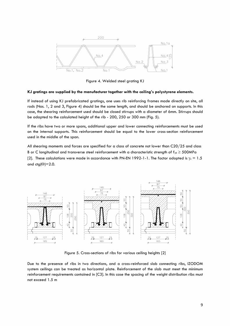
The main reinforcement of the ceiling ribs constitutes KJ gratings, factory-made as welded frames (Fig.
4) using RB500W steel rods with a characteristic strength of fyk=500MPa. The lower gratings type
reinforcement is designed for the distribution of bending moments by a shortening of No.2 and No.3
rods.
9
Figure 4. Welded steel grating KJ
KJ gratings are supplied by the manufacturer together with the ceiling’s polystyrene elements.
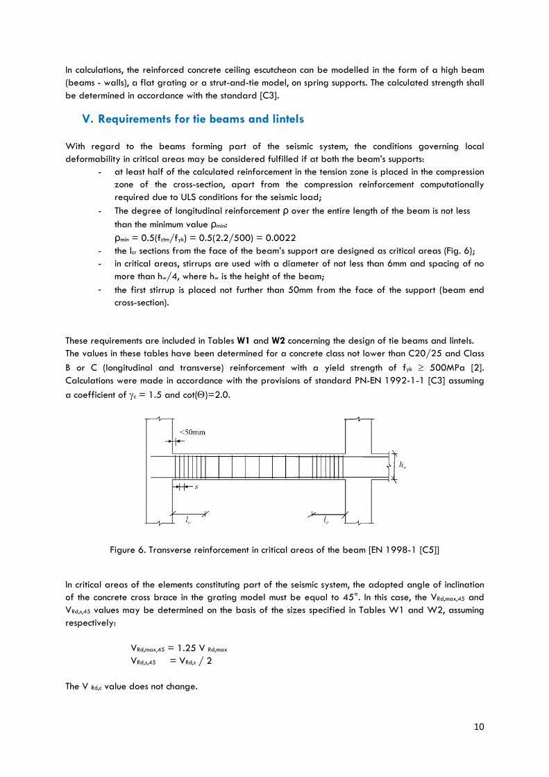
If instead of using KJ prefabricated gratings, one uses rib reinforcing frames made directly on site, all
rods (Nos. 1, 2 and 3, Figure 4) should be the same length, and should be anchored on supports. In this
case, the shearing reinforcement used should be closed stirrups with a diameter of 6mm. Stirrups should
be adapted to the calculated height of the rib - 200, 250 or 300 mm (Fig. 5).
If the ribs have two or more spans, additional upper and lower connecting reinforcements must be used
on the internal supports. This reinforcement should be equal to the lower cross-section reinforcement
used in the middle of the span.
All shearing moments and forces are specified for a class of concrete not lower than C20/25 and class
B or C longitudinal and transverse steel reinforcement with a characteristic strength of fyk 500MPa
[2]. These calculations were made in accordance with PN-EN 1992-1-1. The factor adopted is c = 1.5
and ctg()=2.0.
Figure 5. Cross-sections of ribs for various ceiling heights [2]
Due to the presence of ribs in two directions, and a cross-reinforced slab connecting ribs, IZODOM
system ceilings can be treated as horizontal plate. Reinforcement of the slab must meet the minimum
reinforcement requirements contained in [C3]. In this case the spacing of the weight distribution ribs must
not exceed 1.5 m
10
In calculations, the reinforced concrete ceiling escutcheon can be modelled in the form of a high beam
(beams - walls), a flat grating or a strut-and-tie model, on spring supports. The calculated strength shall
be determined in accordance with the standard [C3].
V. Requirements for tie beams and lintels
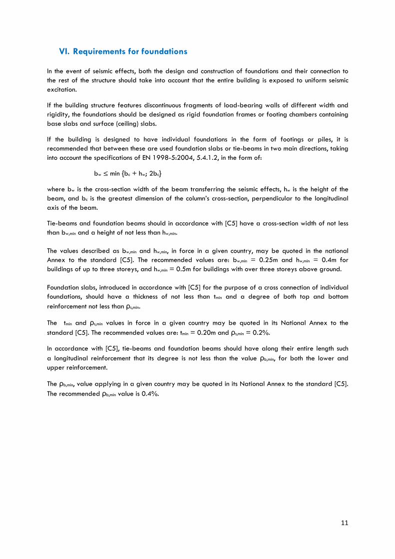
With regard to the beams forming part of the seismic system, the conditions governing local
deformability in critical areas may be considered fulfilled if at both the beam’s supports:
- at least half of the calculated reinforcement in the tension zone is placed in the compression
zone of the cross-section, apart from the compression reinforcement computationally
required due to ULS conditions for the seismic load;
- The degree of longitudinal reinforcement ρ over the entire length of the beam is not less
than the minimum value ρmin:
ρmin = 0.5(fctm/fyk) = 0.5(2.2/500) = 0.0022
- the lcr sections from the face of the beam’s support are designed as critical areas (Fig. 6);
- in critical areas, stirrups are used with a diameter of not less than 6mm and spacing of no
more than hw/4, where hw is the height of the beam;
- the first stirrup is placed not further than 50mm from the face of the support (beam end
cross-section).
These requirements are included in Tables W1 and W2 concerning the design of tie beams and lintels.
The values in these tables have been determined for a concrete class not lower than C20/25 and Class
B or C (longitudinal and transverse) reinforcement with a yield strength of fyk 500MPa [2].
Calculations were made in accordance with the provisions of standard PN-EN 1992-1-1 [C3] assuming
a coefficient of c = 1.5 and cot()=2.0.
Figure 6. Transverse reinforcement in critical areas of the beam [EN 1998-1 [C5]]
In critical areas of the elements constituting part of the seismic system, the adopted angle of inclination
of the concrete cross brace in the grating model must be equal to 45°. In this case, the VRd,max,45 and
VRd,s,45 values may be determined on the basis of the sizes specified in Tables W1 and W2, assuming
respectively:
VRd,max,45 = 1.25 V Rd,max
VRd,s,45 = VRd,s / 2
The V Rd,c value does not change.
11
VI. Requirements for foundations
In the event of seismic effects, both the design and construction of foundations and their connection to
the rest of the structure should take into account that the entire building is exposed to uniform seismic
excitation.
If the building structure features discontinuous fragments of load-bearing walls of different width and
rigidity, the foundations should be designed as rigid foundation frames or footing chambers containing
base slabs and surface (ceiling) slabs.
If the building is designed to have individual foundations in the form of footings or piles, it is
recommended that between these are used foundation slabs or tie-beams in two main directions, taking
into account the specifications of EN 1998-5:2004, 5.4.1.2, in the form of:
bw ≤ min {bc + hw; 2bc}
where bw is the cross-section width of the beam transferring the seismic effects, hw is the height of the
beam, and bc is the greatest dimension of the column’s cross-section, perpendicular to the longitudinal
axis of the beam.
Tie-beams and foundation beams should in accordance with [C5] have a cross-section width of not less
than bw,min and a height of not less than hw,min.
The values described as bw,min and hw,min, in force in a given country, may be quoted in the national
Annex to the standard [C5]. The recommended values are: bw,min = 0.25m and hw,min = 0.4m for
buildings of up to three storeys, and hw,min = 0.5m for buildings with over three storeys above ground.
Foundation slabs, introduced in accordance with [C5] for the purpose of a cross connection of individual
foundations, should have a thickness of not less than tmin and a degree of both top and bottom
reinforcement not less than ρs,min.
The tmin and ρs,min values in force in a given country may be quoted in its National Annex to the
standard [C5]. The recommended values are: tmin = 0.20m and ρs,min = 0.2%.
In accordance with [C5], tie-beams and foundation beams should have along their entire length such
a longitudinal reinforcement that its degree is not less than the value ρb,min, for both the lower and
upper reinforcement.
The ρb,min, value applying in a given country may be quoted in its National Annex to the standard [C5].
The recommended ρb,min value is 0.4%.
12
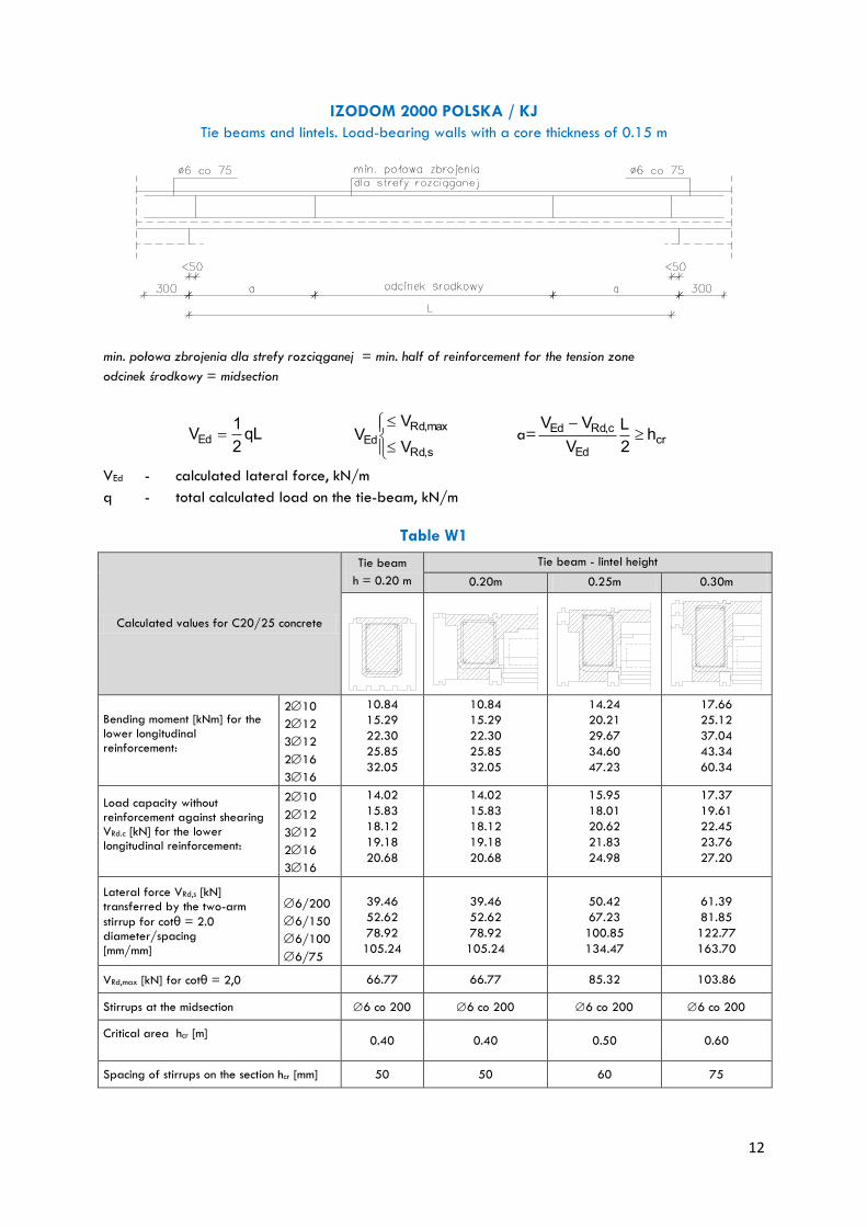
IZODOM 2000 POLSKA / KJ
Tie beams and lintels. Load-bearing walls with a core thickness of 0.15 m
min. połowa zbrojenia dla strefy rozciąganej = min. half of reinforcement for the tension zone
odcinek środkowy = midsection
qL2
1VEd
s,Rd
max,Rd
EdV
VV a= cr
Ed
c,RdEd h2
L
V
VV
VEd - calculated lateral force, kN/m
q - total calculated load on the tie-beam, kN/m
Table W1
Calculated values for C20/25 concrete
Tie beam
h = 0.20 m
Tie beam - lintel height
0.20m 0.25m 0.30m
Bending moment [kNm] for the lower longitudinal reinforcement:
210
212
312
216
316
10.84
15.29
22.30
25.85
32.05
10.84
15.29
22.30
25.85
32.05
14.24
20.21
29.67
34.60
47.23
17.66
25.12
37.04
43.34
60.34
Load capacity without reinforcement against shearing VRd.c [kN] for the lower longitudinal reinforcement:
210
212
312
216
316
14.02
15.83
18.12
19.18
20.68
14.02
15.83
18.12
19.18
20.68
15.95
18.01
20.62
21.83
24.98
17.37
19.61
22.45
23.76
27.20
Lateral force VRd,s [kN] transferred by the two-arm
stirrup for cotθ = 2.0 diameter/spacing [mm/mm]
6/200
6/150
6/100
6/75
39.46
52.62
78.92
105.24
39.46
52.62
78.92
105.24
50.42
67.23
100.85
134.47
61.39
81.85
122.77
163.70
VRd,max [kN] for cotθ = 2,0 66.77 66.77 85.32 103.86
Stirrups at the midsection 6 co 200 6 co 200 6 co 200 6 co 200
Critical area hcr [m]
0.40 0.40 0.50 0.60
Spacing of stirrups on the section hcr [mm] 50 50 60 75
13
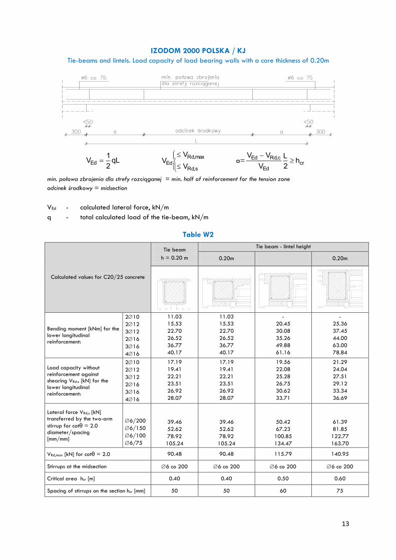
IZODOM 2000 POLSKA / KJ
Tie-beams and lintels. Load capacity of load bearing walls with a core thickness of 0.20m
qL2
1VEd
s,Rd
max,Rd
EdV
VV a= cr
Ed
c,RdEd h2
L
V
VV
min. połowa zbrojenia dla strefy rozciąganej = min. half of reinforcement for the tension zone
odcinek środkowy = midsection
VEd - calculated lateral force, kN/m
q - total calculated load of the tie-beam, kN/m
Table W2
Calculated values for C20/25 concrete
Tie beam
h = 0.20 m
Tie beam - lintel height
0.20m
0.20m
Bending moment [kNm] for the lower longitudinal reinforcement:
210
212
312
216
316
416
11.03
15.53
22.70
26.52
36.77
40.17
11.03
15.53
22.70
26.52
36.77
40.17
-
20.45
30.08
35.26
49.88
61.16
-
25.36
37.45
44.00
63.00
78.84
Load capacity without reinforcement against shearing VRd.c [kN] for the lower longitudinal reinforcement:
210
212
312
216
316
416
17.19
19.41
22.21
23.51
26.92
28.07
17.19
19.41
22.21
23.51
26.92
28.07
19.56
22.08
25.28
26.75
30.62
33.71
21.29
24.04
27.51
29.12
33.34
36.69
Lateral force VRd,s [kN] transferred by the two-arm
stirrup for cotθ = 2.0 diameter/spacing [mm/mm]
6/200
6/150
6/100
6/75
39.46
52.62
78.92
105.24
39.46
52.62
78.92
105.24
50.42
67.23
100.85
134.47
61.39
81.85
122.77
163.70
VRd,max [kN] for cotθ = 2.0 90.48 90.48 115.79 140.95
Stirrups at the midsection 6 co 200 6 co 200 6 co 200 6 co 200
Critical area hcr [m] 0.40 0.40 0.50 0.60
Spacing of stirrups on the section hcr [mm] 50 50 60 75

14