Design of Steel Structures Prof. Damodar Maity Department...
28
Design of Steel Structures Prof. Damodar Maity Department of Civil Engineering Indian Institute of Technology, Guwahati Module - 6 Flexural Members Lecture - 4 Design of laterally unsupported beams Hello, today I am going to focus my lecture on design aspects of laterally unsupported beam. In last lecture we have focused basically on laterally supported beams. Before going to find the difference between laterally unsupported and laterally supported beams first let us see what are the components in a beam member exist. Basically there is 3 components exist: one is compression flange, another is tension flange and then web. Web depth is comparatively high compared to its thickness that is why; there is a tendency of buckling of the web. Now, when the transverse load is coming into picture on the section, if we see the buckling of the section at a particular point we will see that it is buckling due to compression and due to tension. Means, because of the development of bending movement in 1 side it is developing tension bending stress in tension, in other side it is developing on bending stress in compression. So, when bending stress due to compression is happening there it works like a column member;, so the section along the depth of depth its work as a column right. So, when it is working as a column, so there is a chance of buckling. Therefore, the permissible stress will not become 165 which we have considered in case of laterally supported beam. Here permissible stress will become less; permissible stress in bending sigma bc which we considered in case of laterally supported beam as 165 will not be work here; here that value will be less. So, how it will be calculated and how the sigma bc value depends on other parameters that we will see and then we will design accordingly.
Transcript of Design of Steel Structures Prof. Damodar Maity Department...

Design of Steel Structures
Prof. Damodar Maity
Department of Civil Engineering
Indian Institute of Technology, Guwahati
Module - 6
Flexural Members
Lecture - 4
Design of laterally unsupported beams
Hello, today I am going to focus my lecture on design aspects of laterally unsupported
beam. In last lecture we have focused basically on laterally supported beams. Before
going to find the difference between laterally unsupported and laterally supported beams
first let us see what are the components in a beam member exist. Basically there is 3
components exist: one is compression flange, another is tension flange and then web.
Web depth is comparatively high compared to its thickness that is why; there is a
tendency of buckling of the web. Now, when the transverse load is coming into picture
on the section, if we see the buckling of the section at a particular point we will see that
it is buckling due to compression and due to tension. Means, because of the development
of bending movement in 1 side it is developing tension bending stress in tension, in other
side it is developing on bending stress in compression.
So, when bending stress due to compression is happening there it works like a column
member;, so the section along the depth of depth its work as a column right. So, when it
is working as a column, so there is a chance of buckling. Therefore, the permissible
stress will not become 165 which we have considered in case of laterally supported
beam.
Here permissible stress will become less; permissible stress in bending sigma bc which
we considered in case of laterally supported beam as 165 will not be work here; here that
value will be less. So, how it will be calculated and how the sigma bc value depends on
other parameters that we will see and then we will design accordingly.

(Refer Slide Time: 03:33)
As we know 3 components are there: 1 is Compression flange, Tension flange and Web
these 3 components there. Because if we see say suppose I section now, there will 3
component right, so if this is a tension flange and this is compression flange. Now, you
see that this thickness is too less compared to the depth of the web, if this is d and if this
is thickness of the flange. So, there will be chances of buckling if we do not make
support right. So, we have to calculate the allowable compressive stress due to bending
in a different way right.
(Refer Slide Time: 04:40)
Now, if you see how lateral buckling effects if we see say, suppose there is a beam in
flange if we see. And if suppose say I section is provided like this, then what will
happen. So, because of load it will act locally as a compressive member and this will
buckle say maybe like this it will buckle right. So, this will buckle like this, this is the
center line right this is the original position and.
So, this is before buckling and this is the buckling beam means, after loading right. Now,
if we see the cross section we will see that this is the I section before buckling, this is
before and after buckling say this will become something like this right. So, this is after
this is the plane of the beam right. So, what we are seeing that because of the
concentrated load this will try to buckle this portion should try to buckle.
So, in plane we will see like this right, so we have to find out the chances of buckling
how much it may happen means, what are the parameters depends on buckling and how
we can restrict. And because of buckling what will be the possible stresses; allowable
stresses that we have to find out then only we can go for design. And design will be
almost similar way, as what we have done in case of design of supported laterally
supported beam.
(Refer Slide Time: 07:09)
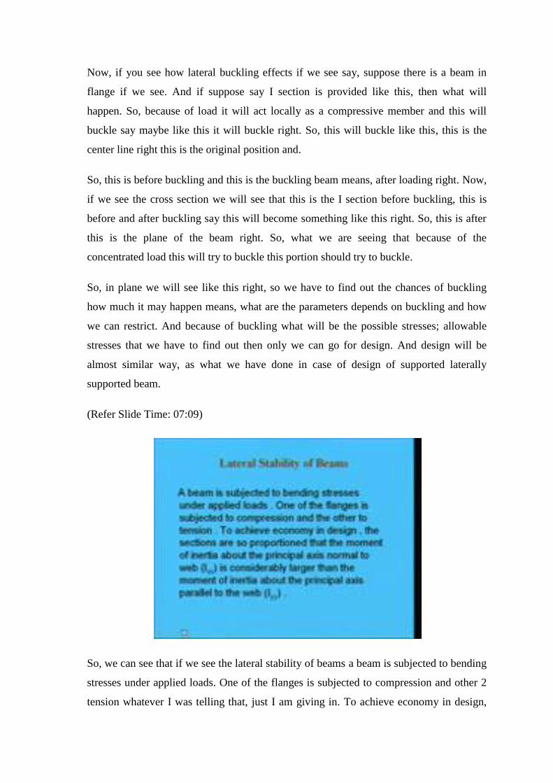
So, we can see that if we see the lateral stability of beams a beam is subjected to bending
stresses under applied loads. One of the flanges is subjected to compression and other 2
tension whatever I was telling that, just I am giving in. To achieve economy in design,

the sections are so proportioned that the moment of inertia about the principal axis
normal to web Ixx is considerably larger than the moment of inertia about the principal
axis parallel to the web.
That means, generally to make economic we make like this, because the bucking means
when the section is there. So, if buckle in this way right about this axis that is why we
will try to make this and to make this larger and to make this lesser this width become
less and depth of this web become as high as possible. And therefore, the chances of
buckling occurs.
(Refer Slide Time: 08:25)
You see such a section is weak in bending resistance in the plane normal to the web,
therefore, the compression flange of the beam tends to buckle. This buckling increases
with increase in the ratio of moment of inertia about the xx axis to that of yy axis. If the
compression flange of a beam can be restrained against lateral buckling by any means,
the allowable bending stress can be utilized to their value. So, 1 option to increase the
bending stress in compression is, to provide some lateral support in the web, so that
lateral buckling can be restricted. So, this is one way to increase the moment carrying
capacity of the flexural member by providing lateral support.
(Refer Slide Time: 09:26)
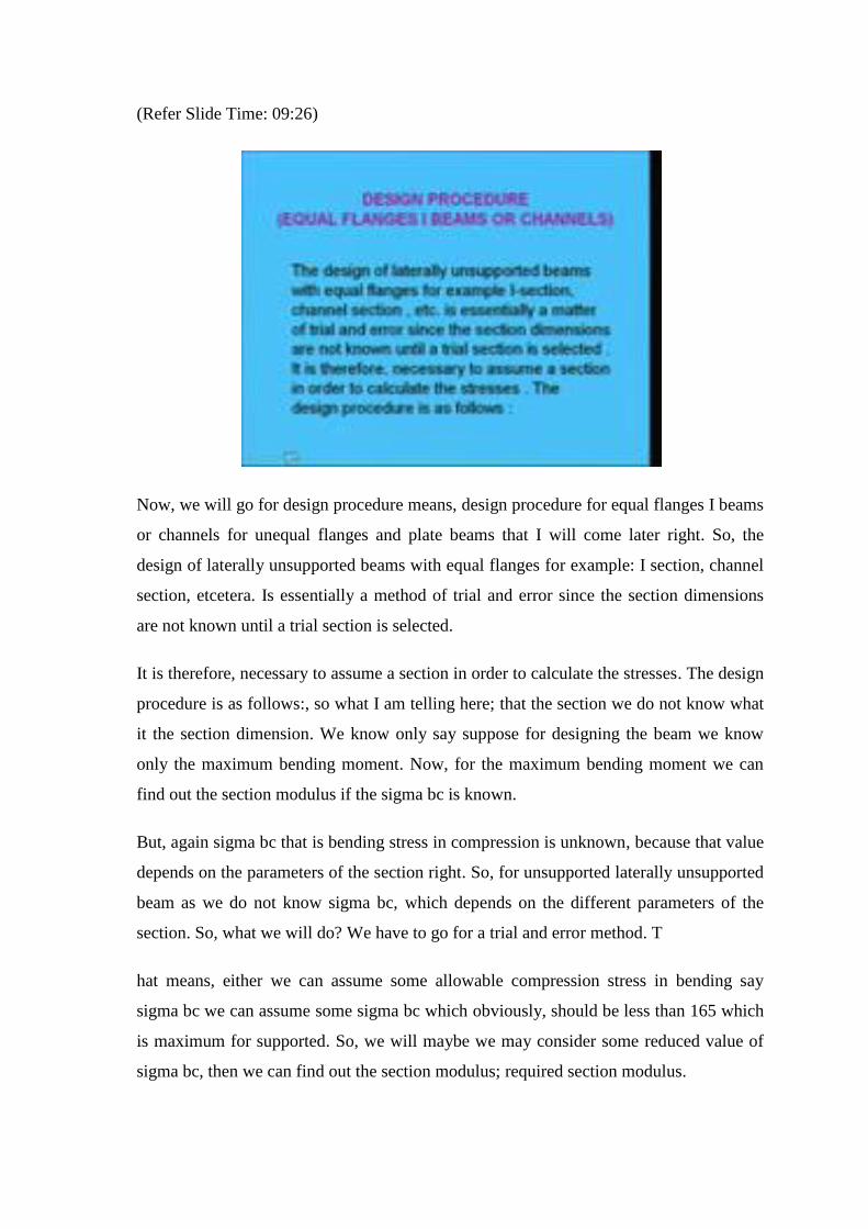
Now, we will go for design procedure means, design procedure for equal flanges I beams
or channels for unequal flanges and plate beams that I will come later right. So, the
design of laterally unsupported beams with equal flanges for example: I section, channel
section, etcetera. Is essentially a method of trial and error since the section dimensions
are not known until a trial section is selected.
It is therefore, necessary to assume a section in order to calculate the stresses. The design
procedure is as follows:, so what I am telling here; that the section we do not know what
it the section dimension. We know only say suppose for designing the beam we know
only the maximum bending moment. Now, for the maximum bending moment we can
find out the section modulus if the sigma bc is known.
But, again sigma bc that is bending stress in compression is unknown, because that value
depends on the parameters of the section right. So, for unsupported laterally unsupported
beam as we do not know sigma bc, which depends on the different parameters of the
section. So, what we will do? We have to go for a trial and error method. T
hat means, either we can assume some allowable compression stress in bending say
sigma bc we can assume some sigma bc which obviously, should be less than 165 which
is maximum for supported. So, we will maybe we may consider some reduced value of
sigma bc, then we can find out the section modulus; required section modulus.
Then, according to that required section modulus what we will do we will find out the
appropriate section. And, then for that particular section which we have chosen what will
be the actual sigma bc permissible stress in compression what will be, so that we will
find out. After finding out that 1, we can check whether the moment resistance capacity
of the selected section is ok or not; that means, is more than the applied moment or not.
So, in this way we can design an appropriate section. So, what we are seen here? That it
is a trial and error method by trial and error we have to choose a suitable section. Maybe
sometimes we may choose a very conservative section means, over conservative we can
make in that case again we have to reduce to make it economic. And sometimes we may
choose little lesser than the actual 1, so in that case we have to increase that 1.
There is 2 way to start with: 1 is that reduce the sigma bc value from 165 assume the
sigma bc value say maybe 50 percent less than that right. Otherwise 50 percent or say 20
percent it depends on the experience of the engineers and what type of sections we are
going to consider it depends on that. Otherwise, let assume sigma bc as 165 then let us
find out the required section modulus. Then, maybe 30 to 50 percent we can increase the
section modulus to choose the choose a suitable section from the IS handbook. So, in this
way also can be done; there is 2 method finally, it will come same.
(Refer Slide Time: 13:37)
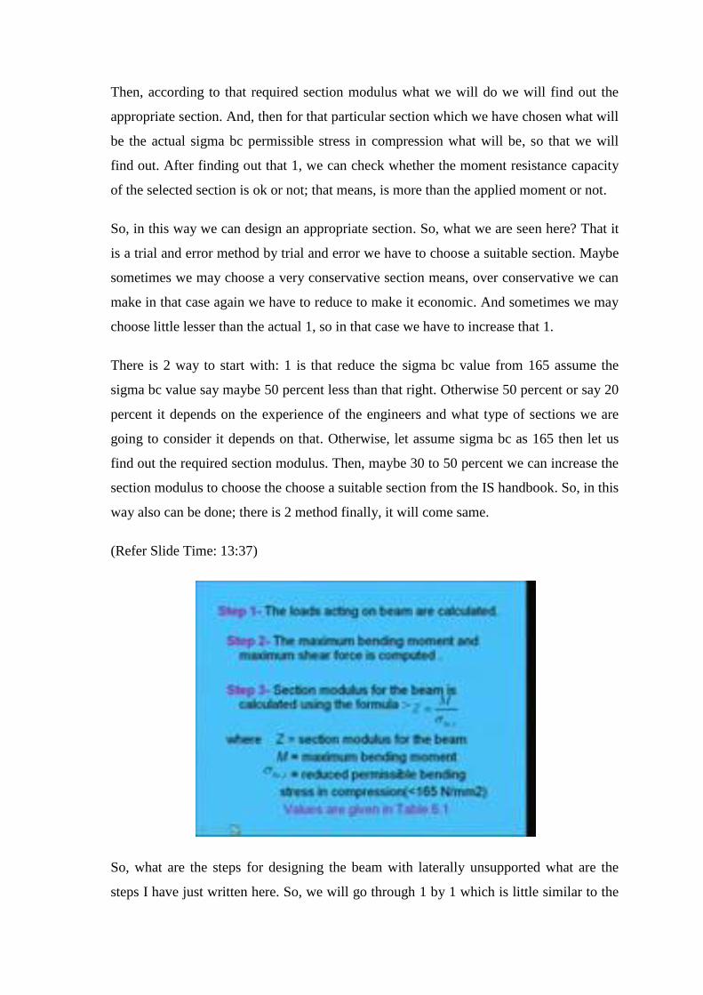
So, what are the steps for designing the beam with laterally unsupported what are the
steps I have just written here. So, we will go through 1 by 1 which is little similar to the
design of supported beams laterally supported beams. Only here difference will be that
as we have to go for trial and error, so little difference will be there. And how to find out
sigma bc which is not required to find out in case of laterally supported beam as it is 0.66
fy in case of fy 250 it is 165.
So, we can directly consider that 1 but in this case we have to calculate the value
properly. So, in first step what we will do first as we know that loads acting on beam has
to calculate. What are the loads are acting? That has to be calculated. Remember we have
to see if it is imposed load then that dead load or; that means, the self weight of the beam
has to be also considered.
In this case as we do not know the section, so some appropriate self weight we can
assume, then on that basis we can choose the section. Then, again we have to check
whether the actual section is capable of taking that much load or not, in that way we have
to do. In step 2 we will find out the maximum bending moment and maximum shear
force right.
So, because we have to design on the basis of maximum bending moment and maximum
shear force, so we will calculate those things. In step 3 what we will do we will find out
section modulus for the beam using the formula that Z is equal to M by sigma bc or
sigma bt. Now, as we know sigma bc will be what that reduced permissible bending
stress in compression, which will be less than 165 right.
So, from here first what we will do that we will assume some approximate sigma bc,
then we can find out Z. Then, we can find out the section after that for that particular
section we can find out what is the actual sigma bc; which is given in table 6.1. In table
6.1 several tables are there 6.1A to 6.1F for different condition is given I am coming.
(Refer Slide Time: 16:21)
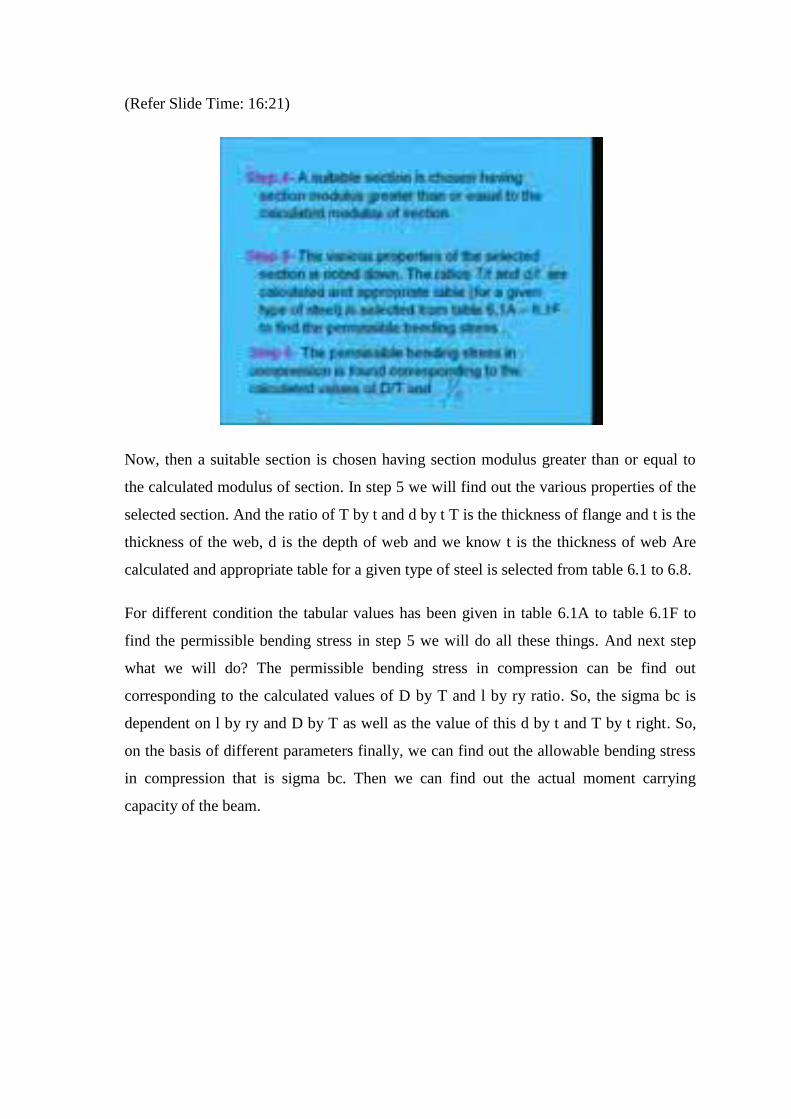
Now, then a suitable section is chosen having section modulus greater than or equal to
the calculated modulus of section. In step 5 we will find out the various properties of the
selected section. And the ratio of T by t and d by t T is the thickness of flange and t is the
thickness of the web, d is the depth of web and we know t is the thickness of web Are
calculated and appropriate table for a given type of steel is selected from table 6.1 to 6.8.
For different condition the tabular values has been given in table 6.1A to table 6.1F to
find the permissible bending stress in step 5 we will do all these things. And next step
what we will do? The permissible bending stress in compression can be find out
corresponding to the calculated values of D by T and l by ry ratio. So, the sigma bc is
dependent on l by ry and D by T as well as the value of this d by t and T by t right. So,
on the basis of different parameters finally, we can find out the allowable bending stress
in compression that is sigma bc. Then we can find out the actual moment carrying
capacity of the beam.

(Refer Slide Time: 18:12)
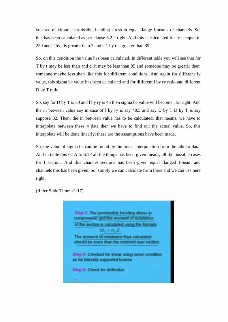
So, step 7 what we will do that the permissible bending stress in compression and the
moment of resistance of the section is calculated using formula: MR is equal to sigma bc
into Z, where the moment of resistance is calculated it should be more than the moment
over the section. So, in this way we can find out the moment of resistance which is sigma
bc into Z, where Z is the section modulus.
(Refer Slide Time: 18:46)
Now, as I told sigma bc can be find out from 6.1 that is this 1. You see here 1 just sample
table I have shown which has been taken from IS 8984. This is table 6.1 A it is written
you see maximum permissible bending stress in equal flange I-beams or channels. So,
this has been calculated as per clause 6.2.2 right. And this is calculated for fy is equal to
250 and T by t is greater than 2 and d 1 by t is greater than 85.
So, on this condition the value has been calculated. In different table you will see that for
T by t may be less than and d 1t may be less than 85 and someone may be greater than,
someone maybe less than like this for different conditions. And again for different fy
value, this sigma bc value has been calculated and for different l by ry ratio and different
D by T ratio.
So, say for D by T is 30 and l by ry is 45 then sigma bc value will become 155 right. And
the in between value say in case of l by ry is say 40.5 and say D by T D by T is say
suppose 32. Then, the in between value has to be calculated; that means, we have to
interpolate between these 4 data then we have to find out the actual value. So, this
interpolate will be done linearly; these are the assumptions have been made.
So, the value of sigma bc can be found by the linear interpolation from the tabular data.
And in table this 6.1A to 6.1F all the things has been given means, all the possible cases
for I section. And this channel sections has been given equal flanged I-beam and
channels this has been given. So, simply we can calculate from there and we can use here
right.
(Refer Slide Time: 21:17)
Next step is step 8, so once we find out a suitable section from bending moment point of
view, then we can go for checking of shear. How do we make checks here? As we have
done in case of earlier; that means, we will find out what is the maximum shear then we
can find out average shear stress; what is developing and the allowable shear stress,
whether it is less than that or not we have to check and accordingly we have to act right.
So, check for shear using same condition as for laterally supported beams and check for
deflection that is also same case. Deflection we know, that has to be less than span by
325 as per the Codal provision So, for a particular end condition and loading condition
we can find out what it the deflection is coming and from the Codal provision we can
find out what is the maximum allowable deflections span by 325.
So, if the developed deflection is less than the allowable deflection then this is means,
the selected section is otherwise, we have to change the selected section. Now, we will
go through 1 worked out example; the example is will be basis on the design steps
whatever we have discussed earlier right.
(Refer Slide Time: 25:56)
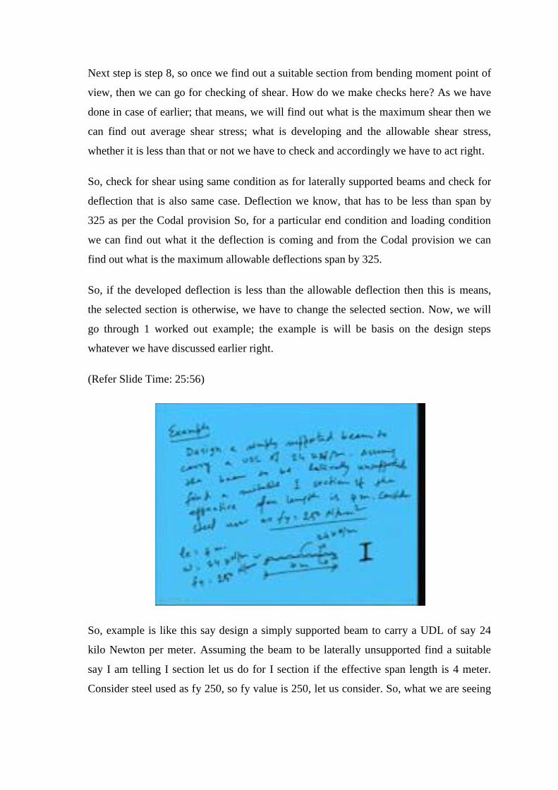
So, example is like this say design a simply supported beam to carry a UDL of say 24
kilo Newton per meter. Assuming the beam to be laterally unsupported find a suitable
say I am telling I section let us do for I section if the effective span length is 4 meter.
Consider steel used as fy 250, so fy value is 250, let us consider. So, what we are seeing
that is simply supported beam having a UDL load is 24 kilo Newton per meter and
having 4 meter length.
So, le is equal to 4 meter w is equal to 24 kilo Newton per meter fy is equal 250 Newton
per millimeter square. So, if I make like this means the cross section it is already told this
would be I section right. So, what we will do? This is the question that we are going to
use I section first of all we have a UDL load of 24 kilo Newton per meter and a length of
4 meter effective length. So, in first step what we will do, what are the total load.
(Refer Slide Time: 29:26)
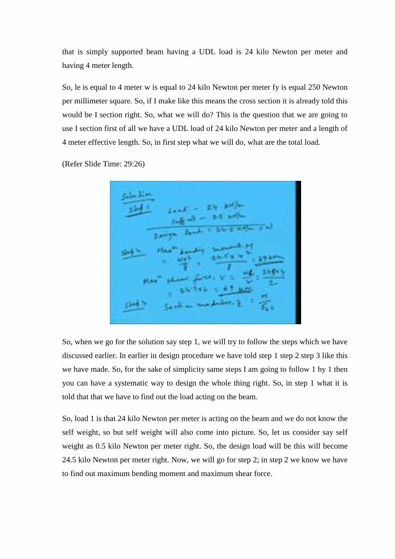
So, when we go for the solution say step 1, we will try to follow the steps which we have
discussed earlier. In earlier in design procedure we have told step 1 step 2 step 3 like this
we have made. So, for the sake of simplicity same steps I am going to follow 1 by 1 then
you can have a systematic way to design the whole thing right. So, in step 1 what it is
told that that we have to find out the load acting on the beam.
So, load 1 is that 24 kilo Newton per meter is acting on the beam and we do not know the
self weight, so but self weight will also come into picture. So, let us consider say self
weight as 0.5 kilo Newton per meter right. So, the design load will be this will become
24.5 kilo Newton per meter right. Now, we will go for step 2; in step 2 we know we have
to find out maximum bending moment and maximum shear force.
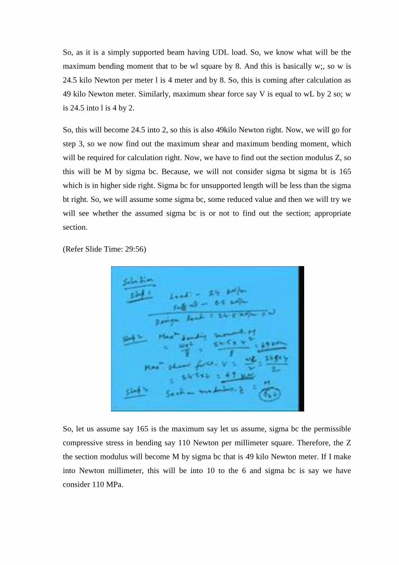
So, as it is a simply supported beam having UDL load. So, we know what will be the
maximum bending moment that to be wl square by 8. And this is basically w;, so w is
24.5 kilo Newton per meter l is 4 meter and by 8. So, this is coming after calculation as
49 kilo Newton meter. Similarly, maximum shear force say V is equal to wL by 2 so; w
is 24.5 into l is 4 by 2.
So, this will become 24.5 into 2, so this is also 49kilo Newton right. Now, we will go for
step 3, so we now find out the maximum shear and maximum bending moment, which
will be required for calculation right. Now, we have to find out the section modulus Z, so
this will be M by sigma bc. Because, we will not consider sigma bt sigma bt is 165
which is in higher side right. Sigma bc for unsupported length will be less than the sigma
bt right. So, we will assume some sigma bc, some reduced value and then we will try we
will see whether the assumed sigma bc is or not to find out the section; appropriate
section.
(Refer Slide Time: 29:56)
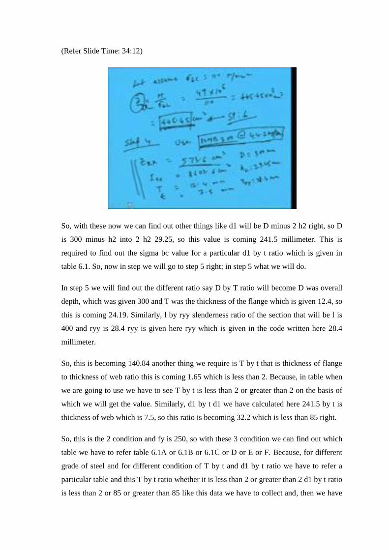
So, let us assume say 165 is the maximum say let us assume, sigma bc the permissible
compressive stress in bending say 110 Newton per millimeter square. Therefore, the Z
the section modulus will become M by sigma bc that is 49 kilo Newton meter. If I make
into Newton millimeter, this will be into 10 to the 6 and sigma bc is say we have
consider 110 MPa.

So, after calculating we will get this as 445.45 into 10 cube millimeter cube or we can
write 445.45 centimeter cube. I am converting into centimeter cube, because in IS code
in SP: 16 SP: 6 it is given the section modulus is given in centimeter that is why I am
convert into centimeter cube right.
Now, so with this value we have to find out an appropriate section. So, in step 4 we will
find out the appropriate section right. So, if we go though the handbook SP: 6 say first
we have told that we are going to use I section. So, in I section we will see what is
nearby 445 centimeter cube and we have to see that the section, whichever we are going
to consider is little higher than this 445.45. So, accordingly we will try to find out.
So, from that we have seen that we can use say ISMB 300 at 44.2 kg per centimeter kg
per meter right. So, we are going to choose this section ISMB 300 at 44.2 kg per meter
right, so in this way we can choose. Now, the moment we are choosing the section we
can find out the required properties; required properties means, 1 is zxx. Because, this is
basically z means zxx right. zxx is 573.6 centimeter cube; that means, you see required z
was 445 and we are providing little high that is 573.6 centimeter cube.
Next, Ixx will be required for calculation that is 8603.6 centimeter cube. Now, thickness
of the flange of the I section is 12.4 millimeter. Similarly, thickness of the web of the
section is 7.5 millimeter right. Again overall depth we know as ISMB 300, so overall
depth will be 300 millimeter. And h2 will become 29.25 which is given in the tabular
form in the code SP: 6. Then, ryy radius of gyration above weaker direction that is 28.4
millimeter right. So, these are the required value which will be necessary for calculating
the sigma bc value and for other purposes right.
(Refer Slide Time: 34:12)
So, with these now we can find out other things like d1 will be D minus 2 h2 right, so D
is 300 minus h2 into 2 h2 29.25, so this value is coming 241.5 millimeter. This is
required to find out the sigma bc value for a particular d1 by t ratio which is given in
table 6.1. So, now in step we will go to step 5 right; in step 5 what we will do.
In step 5 we will find out the different ratio say D by T ratio will become D was overall
depth, which was given 300 and T was the thickness of the flange which is given 12.4, so
this is coming 24.19. Similarly, l by ryy slenderness ratio of the section that will be l is
400 and ryy is 28.4 ryy is given here ryy which is given in the code written here 28.4
millimeter.
So, this is becoming 140.84 another thing we require is T by t that is thickness of flange
to thickness of web ratio this is coming 1.65 which is less than 2. Because, in table when
we are going to use we have to see T by t is less than 2 or greater than 2 on the basis of
which we will get the value. Similarly, d1 by t d1 we have calculated here 241.5 by t is
thickness of web which is 7.5, so this ratio is becoming 32.2 which is less than 85 right.
So, this is the 2 condition and fy is 250, so with these 3 condition we can find out which
table we have to refer table 6.1A or 6.1B or 6.1C or D or E or F. Because, for different
grade of steel and for different condition of T by t and d1 by t ratio we have to refer a
particular table and this T by t ratio whether it is less than 2 or greater than 2 d1 by t ratio
is less than 2 or 85 or greater than 85 like this data we have to collect and, then we have
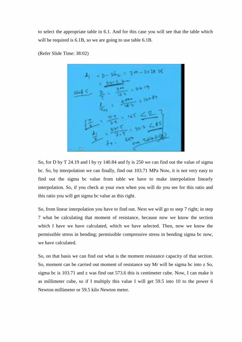
to select the appropriate table in 6.1. And for this case you will see that the table which
will be required is 6.1B, so we are going to use table 6.1B.
(Refer Slide Time: 38:02)
So, for D by T 24.19 and l by ry 140.84 and fy is 250 we can find out the value of sigma
bc. So, by interpolation we can finally, find out 103.71 MPa Now, it is not very easy to
find out the sigma bc value from table we have to make interpolation linearly
interpolation. So, if you check at your own when you will do you see for this ratio and
this ratio you will get sigma bc value as this right.
So, from linear interpolation you have to find out. Next we will go to step 7 right; in step
7 what be calculating that moment of resistance, because now we know the section
which I have we have calculated, which we have selected. Then, now we know the
permissible stress in bending; permissible compressive stress in bending sigma bc now,
we have calculated.
So, on that basis we can find out what is the moment resistance capacity of that section.
So, moment can be carried out moment of resistance say Mr will be sigma bc into z So,
sigma bc is 103.71 and z was find out 573.6 this is centimeter cube. Now, I can make it
as millimeter cube, so if I multiply this value I will get 59.5 into 10 to the power 6
Newton millimeter or 59.5 kilo Newton meter.

So, Mr the moment of resistance we are going to get as 59.5 kilo Newton meter. So, this
much moment can be carried by the selected section. Now, we have to see what is the
actual moment is coming, because now we cannot assume that moment we have
calculated earlier 49 right.
(Refer Slide Time: 40:48)
We have calculated on the basis of that load is 24 and self weight is 0.5 we have
assumed. Now, for that particular section we know the self weight, so now we will
calculate the actual 1. That what is the actual self weight? And, then what will be actual
total load and actual moment developing right. So, here actual load will be on beam that
will be 1 is 24 kilo Newton per meter.
(Refer Slide Time: 41:45)
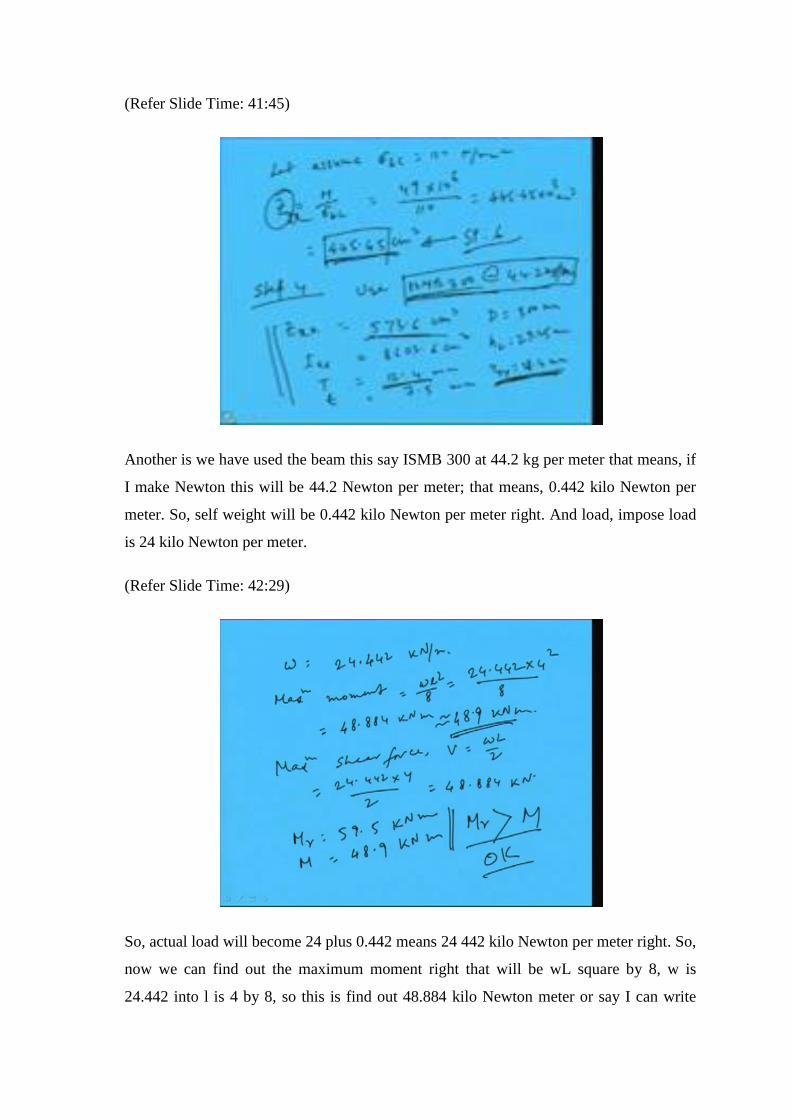
Another is we have used the beam this say ISMB 300 at 44.2 kg per meter that means, if
I make Newton this will be 44.2 Newton per meter; that means, 0.442 kilo Newton per
meter. So, self weight will be 0.442 kilo Newton per meter right. And load, impose load
is 24 kilo Newton per meter.
(Refer Slide Time: 42:29)
So, actual load will become 24 plus 0.442 means 24 442 kilo Newton per meter right. So,
now we can find out the maximum moment right that will be wL square by 8, w is
24.442 into l is 4 by 8, so this is find out 48.884 kilo Newton meter or say I can write

48.9 kilo Newton meter. And maximum shear force on the basis we have to design,
which is actual wL by 2, so this will become 24.442 into 4 by 2 that is 48.884 kilo
Newton.
So, what we are seeing here? That moment of resistance is coming here we got 59.5 kilo
Newton meter. And moment develop is 48.9 kilo Newton meter right that means,
moment of resistance is greater than the developed moment. So, the design is say; that
means, from moment point of view the section is ok right. So, I think you have
understood how to find out the appropriate section.
Now, you must have understood that if I do not put the trial sigma bc as 110 say suppose,
I am putting say 130 or 140 then definitely we may have to go for a design. Because, it
may not come properly right, because if we put more value section modulus will be less
and in that case if section modulus is less, then the we can find out the lesser section and
then the sigma bc value will become very less.
So, maybe if the sigma bc value whatever we calculating means, whatever coming for a
particular section is less than the assumed 1 then section will going to fail, so we have to
redesign right. So, it is basically a trial and error process through which we can make.
Now, if we can develop software on this, then easily we can find out a economic section.
Because, there we do not need to do all this manual things right just by computer, just by
fraction of a second it can find out the appropriate section.
How? What we will do? We will start with a trial section and we will go on checking
that at what Z section it is coming for 50 not more than that or not less than that. So, by
iteration by giving some number of iteration we will means computer will search, which
section is going fit for that particular load; which section is giving most economic
section for that particular load and boundary conditions. So, those things can be find out
if 1 can write a program properly for the design purpose of the beam right. I will show
some software which has been developed by my students in conjugative classes.
(Refer Slide Time: 46:48)
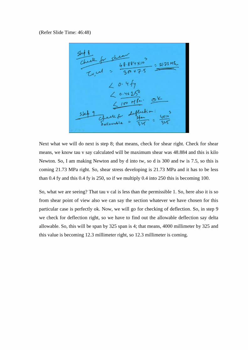
Next what we will do next is step 8; that means, check for shear right. Check for shear
means, we know tau v say calculated will be maximum shear was 48.884 and this is kilo
Newton. So, I am making Newton and by d into tw, so d is 300 and tw is 7.5, so this is
coming 21.73 MPa right. So, shear stress developing is 21.73 MPa and it has to be less
than 0.4 fy and this 0.4 fy is 250, so if we multiply 0.4 into 250 this is becoming 100.
So, what we are seeing? That tau v cal is less than the permissible 1. So, here also it is so
from shear point of view also we can say the section whatever we have chosen for this
particular case is perfectly ok. Now, we will go for checking of deflection. So, in step 9
we check for deflection right, so we have to find out the allowable deflection say delta
allowable. So, this will be span by 325 span is 4; that means, 4000 millimeter by 325 and
this value is becoming 12.3 millimeter right, so 12.3 millimeter is coming.

(Refer Slide Time: 49:14)
So, delta allowable is becoming 12.3 millimeter. Now, what is the developed deflection
means, delta calculated that will be for this particular boundary conditions this will be 5
by 384 into wl to the 4 by EI right. Because, this is a simply supported with UDL, so for
this the coefficient is 5 by 384 as for the Codal provision we know or theoretically we
can find also right.
So, if we put the values we can find out all details say w was we calculated 24.442 into l
is 4 meter; that means, 4000 millimeter wl to the 4 by EI; E is 2 into 10 to the power 5
and I is given in the code means we have calculated already means, we have extracted
here from the table I.

(Refer Slide Time: 50:30)
This is 8603.6 centimeter cube, so those things we will provide here right. So, 8603.6
this is centimeter it was centimeter to the 4. So, we are making millimeter to make in
centimeter. So, if we calculate we are going to get 4.735 millimeter this is less than delta
allowable which is 12.33 millimeter; that means, from deflection point of view this is ok.
So, the deflection due to the load is coming 4.735 millimeter and allowable deflection for
this particular case is given 12.3 millimeter. So, from this we can say that this is perfectly
ok. So, I hope now it is clear that how to design a beam with unsupported condition; that
means, laterally unsupported beam how to design is clear of course, it is equal flange.
Now, for unequal flanges how to design now let us discus.
(Refer Slide Time: 51:57)
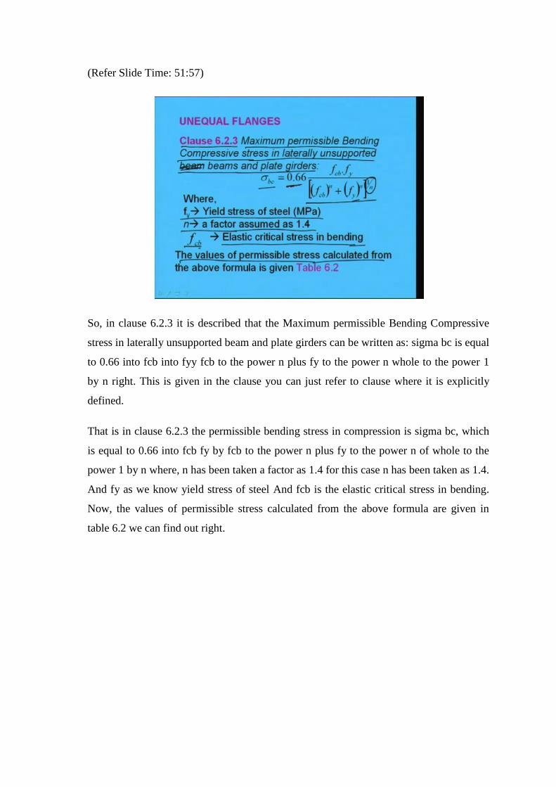
So, in clause 6.2.3 it is described that the Maximum permissible Bending Compressive
stress in laterally unsupported beam and plate girders can be written as: sigma bc is equal
to 0.66 into fcb into fyy fcb to the power n plus fy to the power n whole to the power 1
by n right. This is given in the clause you can just refer to clause where it is explicitly
defined.
That is in clause 6.2.3 the permissible bending stress in compression is sigma bc, which
is equal to 0.66 into fcb fy by fcb to the power n plus fy to the power n of whole to the
power 1 by n where, n has been taken a factor as 1.4 for this case n has been taken as 1.4.
And fy as we know yield stress of steel And fcb is the elastic critical stress in bending.
Now, the values of permissible stress calculated from the above formula are given in
table 6.2 we can find out right.
(Refer Slide Time: 53:31)
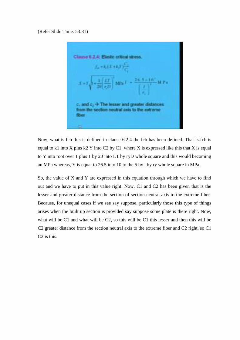
Now, what is fcb this is defined in clause 6.2.4 the fcb has been defined. That is fcb is
equal to k1 into X plus k2 Y into C2 by C1, where X is expressed like this that X is equal
to Y into root over 1 plus 1 by 20 into LT by ryD whole square and this would becoming
an MPa whereas, Y is equal to 26.5 into 10 to the 5 by l by ry whole square in MPa.
So, the value of X and Y are expressed in this equation through which we have to find
out and we have to put in this value right. Now, C1 and C2 has been given that is the
lesser and greater distance from the section of section neutral axis to the extreme fiber.
Because, for unequal cases if we see say suppose, particularly those this type of things
arises when the built up section is provided say suppose some plate is there right. Now,
what will be C1 and what will be C2, so this will be C1 this lesser and then this will be
C2 greater distance from the section neutral axis to the extreme fiber and C2 right, so C1
C2 is this.

(Refer Slide Time: 55:20)
Next k1, because here some factors are given this k1 k2, so what is k1? Is a coefficient to
allow for reduction in thickness or breadth of flange between points of effective lateral
restraint, which depends upon a ratio psi, whose value against k1 has been given in table
6.3. So, the values of k1 is given in table 6.3 which depends on value of psi. What is psi?
Psi is the ratio of the total area of the flanges at the point of least bending moment to the
corresponding area at the point of greatest bending moment between such points of
restraint right. So, all these things in fact is given in the code from which we have taken
code means this IS: 800 1984. Then, k2 is a coefficient to allow for the inequality of
flanges and depends on omega which is given in table in 6.4 of IS: 800. So, it will again
depends on omega which is given in IS: 800 in table 6.4.
(Refer Slide Time: 56:48)
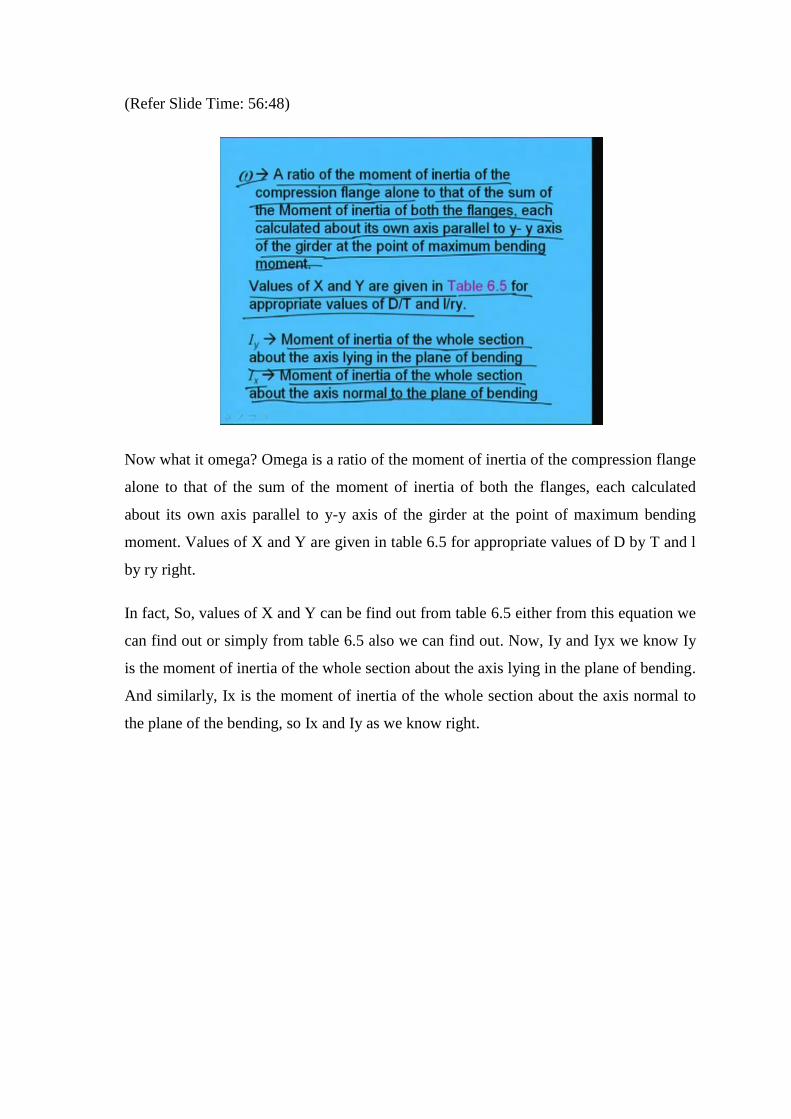
Now what it omega? Omega is a ratio of the moment of inertia of the compression flange
alone to that of the sum of the moment of inertia of both the flanges, each calculated
about its own axis parallel to y-y axis of the girder at the point of maximum bending
moment. Values of X and Y are given in table 6.5 for appropriate values of D by T and l
by ry right.
In fact, So, values of X and Y can be find out from table 6.5 either from this equation we
can find out or simply from table 6.5 also we can find out. Now, Iy and Iyx we know Iy
is the moment of inertia of the whole section about the axis lying in the plane of bending.
And similarly, Ix is the moment of inertia of the whole section about the axis normal to
the plane of the bending, so Ix and Iy as we know right.

(Refer Slide Time: 57:51)
Now, as was telling you that in table it is given like in table 6.3 values of k1 for beams
with curtailed flanges has been given. So, for different psi you can find out values of k1
and similarly, for different omega you can find out the values of k2. So, values of k2 for
beams with unequal flanges. So, from this we can find out values of k1 and k1 from table
6.3 and 6.4.
(Refer Slide Time: 58:28)
And in table 6.5 directly we can find out value of X and Y with the values of D by T and
l by ry. Otherwise, those you are going to develop the software develop the programming
they have to use the equations, because we cannot use the table. Table is used best way is
to use the equation from which we will get directly, whatever in the code in tabular form
is given can be found out directly from the equations.
And if we are going to use through programming we do not have to do anything. So,
complication of the calculation can be avoided, which has to do manually can be avoided
through that computer programming right. And as earlier we are doing in manually, so
code has helped us, code has reduced our work through giving the data in terms of
tabular form, which has been extracted from the equation those complicated equations.
So, in this way we can find out the sigma bc value that is sigma bc is nothing but the
allowable bending stress in compression. In case of unequal flanges we can find out the
permissible stress in bending in compression. And then other processes are exactly same
whatever we have done in case of equal flanges. So, in next class we will discuss about
the unequal flanges then we will see how to solve a problem right. And today as time is
short, so now I like to conclude today’s lecture.
Thank you very much.