Design of Solar/Electric Powered Hybrid Vehicle (SEPHV ... · PDF fileDesign of Solar/Electric...
13
Design of Solar/Electric Powered Hybrid Vehicle (SEPHV) System with Charge Pattern Optimization for Energy Cost T.Balamurugan #1 , Dr.S.Manoharan *2 # Research Scholar, Department of Electrical and Electronics Engineering, Karpagam University, Coimbatore, Tamilnadu, India 1 [email protected] * Professor and Head, Department of Electronics and Instrumentation Engineering, Karpagam College of Engineering, Coimbatore, Tamilnadu, India. 2 [email protected] Abstract— This paper proposes a Solar Electric Powered Hybrid Vehicle (SEPHV) system which solves the major problems of fuel and pollution. An electric vehicle usually uses a battery which has been charged by external electrical power supply. All recent electric vehicles present a drive on AC power supplied motor. An inverter set is required to be connected with the battery through which AC power is converted to DC power. During this conversion many losses take place and also the maintenance cost of the AC System is very high. The proposed topology has the most feasible solar/electric power generation system mounted on the vehicle to charge the battery during all durations. With a view of providing ignited us to develop this “Solar/Electric Powered Hybrid Vehicle” [SEPHV].This multi charging vehicle can charge itself from both solar and electric power. The vehicle is altered out of a Maruti Omni vehicle by replacing its engine with a 1.2HP, 24V Permanent Magnet DC [PMDC] Motor. The Supply to the motor is obtained from a battery set of 12V, 150AH. The household electric supply of 230V is reduced with a step-down transformer to 48V and then it is converted to the DC with a rectifying unit to charge the battery. Two solar panels each with a rating of 230watts are attached to the top of the Vehicle to grab the solar energy and is controlled with a help of charge controller. The SEPHV can be driven by 1.2 HP PMDC motor consisting of two 230 watts PV panel in the voltage rating of 24 V. The power which is absorbed by the PV panel is stored into the four 150 AH 12 V batteries. When there is no presence of sun, electric power supply act as an auxiliary energy source. For controlling speed of the motor, a switch is designed with four tapping, provided with different values of resistance at each tapping. It acts as a speed control switch for Solar/Electric Powered Hybrid Vehicle. This type of technique is to reduce the running cost and increasing the running efficiency of the vehicle. The performance of the SEPHV was found to be satisfactory for the load of four people with the average speed of 45km/hr. The integrated system consisting of Solar module, Charge Controller, Batteries, Boost Converter, Step-down Transformer, Diode Rectifier and PMDC motor which are required for the vehicle. Experimental results are presented to confirm the theoretical analysis. Keyword- Solar module, Batteries, PMDC motor, Charge Controller, Step-down Transformer Diode Rectifier. I. INTRODUCTION The fossil fuel such as petrol and diesel are very expensive way to be extracted and used. The use of fossil fuel based vehicles is one of the major reasons that has accelerated the extraction of these non-renewable resources in an unsustainable way. Further, transportation of these fuel to rural areas itself has become a problem. The major problem is green house effect caused due to this burning of fossil fuel where large amount of CO 2 will be emitted which causes lots of problem. Solar vehicles depend on PV cells to convert sunlight into electricity to drive the PMDC motors. Unlike solar thermal energy which converts solar energy to heat, PV cells directly convert sunlight into electricity. According to recent surveys the fossil fuels are depleting at a fast rate where in and around 50 years the whole fossil fuel in the world must be completely depleted. Therefore it is the need of the time to make a new exploration of natural resources of energy and power among the natural resources available sunlight is the most promising one. Sunlight is considered to be a source of energy which is implemented in various day to day applications. The Solar/Electric Powered Hybrid Vehicle (SEPHV) contains the solar panel, Permanent Magnet DC (PMDC) motor, charge controller, batteries, solenoid control, step down transformer, additional brushes and diode rectifier unit. Diode Rectifier can be used to charge the batteries in normal AC supply during sunless conditions. A zero emission solar/electric vehicle is powered by Photovoltaic/Electric Supply energy by means of solar panels and AC supply with storage of electric energy in batteries [1].The PV array has a particular T.Balamurugan et.al / International Journal of Engineering and Technology (IJET) ISSN : 0975-4024 Vol 5 No 6 Dec 2013-Jan 2014 4543
Transcript of Design of Solar/Electric Powered Hybrid Vehicle (SEPHV ... · PDF fileDesign of Solar/Electric...
Design of Solar/Electric Powered Hybrid Vehicle (SEPHV) System with Charge Pattern
Optimization for Energy Cost T.Balamurugan #1, Dr.S.Manoharan *2
# Research Scholar, Department of Electrical and Electronics Engineering, Karpagam University, Coimbatore, Tamilnadu, India
1 [email protected] * Professor and Head, Department of Electronics and Instrumentation Engineering, Karpagam College of
Engineering, Coimbatore, Tamilnadu, India. 2 [email protected]
Abstract— This paper proposes a Solar Electric Powered Hybrid Vehicle (SEPHV) system which solves the major problems of fuel and pollution. An electric vehicle usually uses a battery which has been charged by external electrical power supply. All recent electric vehicles present a drive on AC power supplied motor. An inverter set is required to be connected with the battery through which AC power is converted to DC power. During this conversion many losses take place and also the maintenance cost of the AC System is very high. The proposed topology has the most feasible solar/electric power generation system mounted on the vehicle to charge the battery during all durations. With a view of providing ignited us to develop this “Solar/Electric Powered Hybrid Vehicle” [SEPHV].This multi charging vehicle can charge itself from both solar and electric power. The vehicle is altered out of a Maruti Omni vehicle by replacing its engine with a 1.2HP, 24V Permanent Magnet DC [PMDC] Motor. The Supply to the motor is obtained from a battery set of 12V, 150AH. The household electric supply of 230V is reduced with a step-down transformer to 48V and then it is converted to the DC with a rectifying unit to charge the battery. Two solar panels each with a rating of 230watts are attached to the top of the Vehicle to grab the solar energy and is controlled with a help of charge controller. The SEPHV can be driven by 1.2 HP PMDC motor consisting of two 230 watts PV panel in the voltage rating of 24 V. The power which is absorbed by the PV panel is stored into the four 150 AH 12 V batteries. When there is no presence of sun, electric power supply act as an auxiliary energy source. For controlling speed of the motor, a switch is designed with four tapping, provided with different values of resistance at each tapping. It acts as a speed control switch for Solar/Electric Powered Hybrid Vehicle. This type of technique is to reduce the running cost and increasing the running efficiency of the vehicle. The performance of the SEPHV was found to be satisfactory for the load of four people with the average speed of 45km/hr. The integrated system consisting of Solar module, Charge Controller, Batteries, Boost Converter, Step-down Transformer, Diode Rectifier and PMDC motor which are required for the vehicle. Experimental results are presented to confirm the theoretical analysis.
Keyword- Solar module, Batteries, PMDC motor, Charge Controller, Step-down Transformer Diode Rectifier.
I. INTRODUCTION The fossil fuel such as petrol and diesel are very expensive way to be extracted and used. The use of
fossil fuel based vehicles is one of the major reasons that has accelerated the extraction of these non-renewable resources in an unsustainable way. Further, transportation of these fuel to rural areas itself has become a problem. The major problem is green house effect caused due to this burning of fossil fuel where large amount of CO2 will be emitted which causes lots of problem. Solar vehicles depend on PV cells to convert sunlight into electricity to drive the PMDC motors. Unlike solar thermal energy which converts solar energy to heat, PV cells directly convert sunlight into electricity. According to recent surveys the fossil fuels are depleting at a fast rate where in and around 50 years the whole fossil fuel in the world must be completely depleted. Therefore it is the need of the time to make a new exploration of natural resources of energy and power among the natural resources available sunlight is the most promising one. Sunlight is considered to be a source of energy which is implemented in various day to day applications.
The Solar/Electric Powered Hybrid Vehicle (SEPHV) contains the solar panel, Permanent Magnet DC (PMDC) motor, charge controller, batteries, solenoid control, step down transformer, additional brushes and diode rectifier unit. Diode Rectifier can be used to charge the batteries in normal AC supply during sunless conditions. A zero emission solar/electric vehicle is powered by Photovoltaic/Electric Supply energy by means of solar panels and AC supply with storage of electric energy in batteries [1].The PV array has a particular
T.Balamurugan et.al / International Journal of Engineering and Technology (IJET)
ISSN : 0975-4024 Vol 5 No 6 Dec 2013-Jan 2014 4543
operating point that can supply the maximum power to the load which is generally called Maximum Power Point (MPP). The maximum power point has a non linear locus where it varies according to the solar irradiance and the cell temperature. To boost the efficiency of the PV system, the MPP has to be tracked and followed by regulating the PV panel to operate at MPP operating voltage point, thus optimizing the production of the electricity [2]. One of the most important points is the construction of the vehicle is that, it is closely related to the chassis design, with the purpose of achieving a structural optimized work. So, in order to make the vehicle move under low power consumption and the redesign of chassis has to be done. The design was conceived from point of view of a high efficiency, light weight and stable transport with reduced costs and zero emission in its operation and in the obtaining of the energy [3].Solar Energy is being used to produce electricity with the help of these technology our aim to make solar energy powered Vehicle in our paper. Main disadvantages of solar energy is such that it is not a constant source of power and the amount of solar energy available keeps on varying throughout the day and at night time it is completely unavailable. So to power our vehicle during the absence of solar energy we designed as alternative method of obtaining power to run the vehicle from the Electric supply.
Solar/Electric Powered Hybrid Vehicle (SEPHV) can charge itself from both solar and electric power. The vehicle is altered out of a ‘Maruti Omni’ by replacing its engine with a 1.2HP, 24V Permanent Magnet DC [PMDC] motor. The electric supply to the motor is obtained from a battery set of 12v, 150AH. Two solar panels each with a rating of 230Watts are attached to the top of the vehicle to grab the solar energy and then it is controlled with the help of charge controller. This is used as a main source of energy to charge the battery. The household electric supply of 230V is reduced with a step down transformer to 24V and then it is converted it to DC with a rectifying unit to charge the battery. This is used as a backup source or auxiliary of energy to charge the battery. The Vehicle can be controlled and can matchup a speed of 45km/hr. The PV/Electric Powered Hybrid Vehicle [SEPHV] is thus a boom to the present world by providing us with fuel free mode of transport.
The paper is organized as follows. The system configuration and overview are discussed in section II. The PMDC Motor and characteristics are discussed in section III. Section IV discusses the overall design procedure of Solar/Electric Powered Hybrid Vehicle [SEPHV]. Section V gives the overall hardware implementation of proposed Solar/Electric Powered Hybrid Vehicle [SEPHV]. Section VI concludes the paper.
II. SYSTEM CONFIGURATION AND OVERVIEW
Fig.1. Overall View of the SEPHV
The Fig.1. represents an overall view of the Solar/Electric Powered Hybrid Vehicle (SEPHV) sun is the main source of energy for the vehicle and electric power supply is the auxiliary source of energy for the vehicle.
In this paper the configuration of the Solar/Electric Powered Hybrid Vehicle (SEPHV) system are composed by solar panels, charge controller, battery bank, PMDC motor, step down transformer, battery charging unit and altered ‘Maruti Omni’ vehicle. Hybrid vehicle carries the energy from the both the solar and normal ac supply. The output power from the solar panel is varied depending up on the light irradiation on the atmosphere conditions. Discrete power from the solar panel is connected to the charge controller circuit and fed to the battery bank circuit. At the same time the continuous power from the ac supply is connected to the step-down transformer (230V/48V) and battery charging unit to battery bank. The electric energy thus formed is being fed to the battery bank. The Vehicle combines the use of electric energy from the three different sources [4]:
T.Balamurugan et.al / International Journal of Engineering and Technology (IJET)
ISSN : 0975-4024 Vol 5 No 6 Dec 2013-Jan 2014 4544
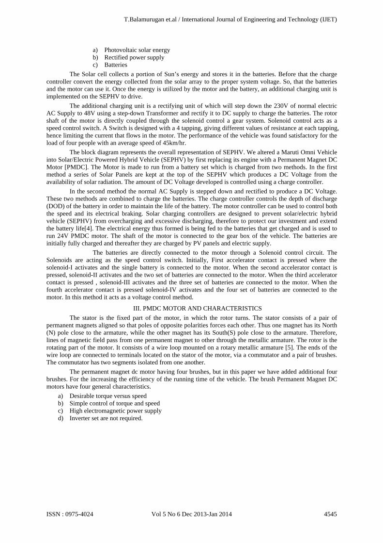
a) Photovoltaic solar energy b) Rectified power supply c) Batteries
The Solar cell collects a portion of Sun’s energy and stores it in the batteries. Before that the charge controller convert the energy collected from the solar array to the proper system voltage. So, that the batteries and the motor can use it. Once the energy is utilized by the motor and the battery, an additional charging unit is implemented on the SEPHV to drive.
The additional charging unit is a rectifying unit of which will step down the 230V of normal electric AC Supply to 48V using a step-down Transformer and rectify it to DC supply to charge the batteries. The rotor shaft of the motor is directly coupled through the solenoid control a gear system. Solenoid control acts as a speed control switch. A Switch is designed with a 4 tapping, giving different values of resistance at each tapping, hence limiting the current that flows in the motor. The performance of the vehicle was found satisfactory for the load of four people with an average speed of 45km/hr.
The block diagram represents the overall representation of SEPHV. We altered a Maruti Omni Vehicle into Solar/Electric Powered Hybrid Vehicle (SEPHV) by first replacing its engine with a Permanent Magnet DC Motor [PMDC]. The Motor is made to run from a battery set which is charged from two methods. In the first method a series of Solar Panels are kept at the top of the SEPHV which produces a DC Voltage from the availability of solar radiation. The amount of DC Voltage developed is controlled using a charge controller.
In the second method the normal AC Supply is stepped down and rectified to produce a DC Voltage. These two methods are combined to charge the batteries. The charge controller controls the depth of discharge (DOD) of the battery in order to maintain the life of the battery. The motor controller can be used to control both the speed and its electrical braking. Solar charging controllers are designed to prevent solar/electric hybrid vehicle (SEPHV) from overcharging and excessive discharging, therefore to protect our investment and extend the battery life[4]. The electrical energy thus formed is being fed to the batteries that get charged and is used to run 24V PMDC motor. The shaft of the motor is connected to the gear box of the vehicle. The batteries are initially fully charged and thereafter they are charged by PV panels and electric supply.
The batteries are directly connected to the motor through a Solenoid control circuit. The Solenoids are acting as the speed control switch. Initially, First accelerator contact is pressed where the solenoid-I activates and the single battery is connected to the motor. When the second accelerator contact is pressed, solenoid-II activates and the two set of batteries are connected to the motor. When the third accelerator contact is pressed , solenoid-III activates and the three set of batteries are connected to the motor. When the fourth accelerator contact is pressed solenoid-IV activates and the four set of batteries are connected to the motor. In this method it acts as a voltage control method.
III. PMDC MOTOR AND CHARACTERISTICS The stator is the fixed part of the motor, in which the rotor turns. The stator consists of a pair of permanent magnets aligned so that poles of opposite polarities forces each other. Thus one magnet has its North (N) pole close to the armature, while the other magnet has its South(S) pole close to the armature. Therefore, lines of magnetic field pass from one permanent magnet to other through the metallic armature. The rotor is the rotating part of the motor. It consists of a wire loop mounted on a rotary metallic armature [5]. The ends of the wire loop are connected to terminals located on the stator of the motor, via a commutator and a pair of brushes. The commutator has two segments isolated from one another. The permanent magnet dc motor having four brushes, but in this paper we have added additional four brushes. For the increasing the efficiency of the running time of the vehicle. The brush Permanent Magnet DC motors have four general characteristics.
a) Desirable torque versus speed b) Simple control of torque and speed c) High electromagnetic power supply d) Inverter set are not required.
T.Balamurugan et.al / International Journal of Engineering and Technology (IJET)
ISSN : 0975-4024 Vol 5 No 6 Dec 2013-Jan 2014 4545
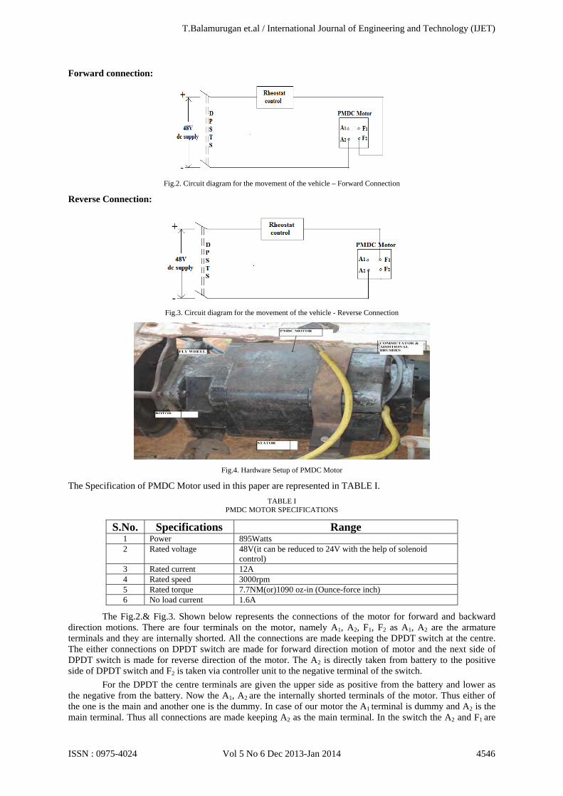
Forward connection:
Fig.2. Circuit diagram for the movement of the vehicle – Forward Connection
Reverse Connection:
Fig.3. Circuit diagram for the movement of the vehicle - Reverse Connection
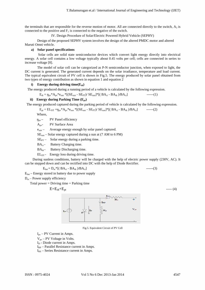
Fig.4. Hardware Setup of PMDC Motor
The Specification of PMDC Motor used in this paper are represented in TABLE I. TABLE I
PMDC MOTOR SPECIFICATIONS
S.No. Specifications Range 1 Power 895Watts 2 Rated voltage 48V(it can be reduced to 24V with the help of solenoid
control) 3 Rated current 12A 4 Rated speed 3000rpm 5 Rated torque 7.7NM(or)1090 oz-in (Ounce-force inch) 6 No load current 1.6A
The Fig.2.& Fig.3. Shown below represents the connections of the motor for forward and backward direction motions. There are four terminals on the motor, namely A1, A2, F1, F2 as A1, A2 are the armature terminals and they are internally shorted. All the connections are made keeping the DPDT switch at the centre. The either connections on DPDT switch are made for forward direction motion of motor and the next side of DPDT switch is made for reverse direction of the motor. The A2 is directly taken from battery to the positive side of DPDT switch and F2 is taken via controller unit to the negative terminal of the switch. For the DPDT the centre terminals are given the upper side as positive from the battery and lower as the negative from the battery. Now the A1, A2 are the internally shorted terminals of the motor. Thus either of the one is the main and another one is the dummy. In case of our motor the A1 terminal is dummy and A2 is the main terminal. Thus all connections are made keeping A2 as the main terminal. In the switch the A2 and F1 are
T.Balamurugan et.al / International Journal of Engineering and Technology (IJET)
ISSN : 0975-4024 Vol 5 No 6 Dec 2013-Jan 2014 4546
the terminals that are responsible for the reverse motion of motor. All are connected directly to the switch, A2 is connected to the positive and F1 is connected to the negative of the switch.
IV. Design Procedure of Solar/Electric Powered Hybrid Vehicle (SEPHV) Design of the proposed SEPHV system involves the design of the altered PMDC motor and altered Maruti Omni vehicle.
a) Solar panel specifications
Solar cells are solid state semiconductor devices which convert light energy directly into electrical energy. A solar cell contains a low voltage typically about 0.45 volts per cell; cells are connected in series to increase voltage [8].
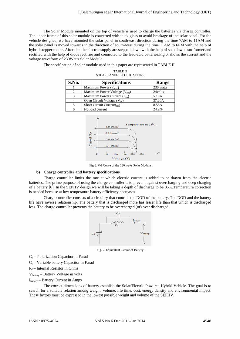
The model of solar cell can be categorized as P-N semiconductor junction, when exposed to light, the DC current is generated. The generated current depends on the solar irradiance, temperature and load current. The typical equivalent circuit of PV cell is shown in Fig.5. The energy produced by solar panel obtained from two types of energy contribution as shown in equation 1 and equation 2
i) Energy during driving time(Edt)
The energy produced during a running period of a vehicle is calculated by the following expression. Edt = ŋpv*Apv*esun *[(SEsun - SEPT)/ SEsun]*[( BAct - BAdt )/BAct] ------(1) ii) Energy during Parking Time (Ept) The energy produced captured during the parking period of vehicle is calculated by the following expression. Ept = ELDT +ŋpv*Apv*esun *[(SEsun - SEPT)/ SEsun]*[( BAct - BAdt )/BAct] ------(2) Where, ŋpv – PV Panel efficiency Apv- PV Surface Area esun – Average energy enough by solar panel captured. SEsun – Solar energy captured during a sun at (7 AM to 6 PM) SEPT – Solar energy during a parking time. BAct - Battery Charging time.
BAdt - Battery Discharging time. ELDT - Energy loss during driving time.
During sunless conditions, battery will be charged with the help of electric power supply (230V, AC). It can be stepped down and can be rectified into DC with the help of Diode Rectifier. Ebat = Ŋac*[( BAct - BAdt )/BAct] ------(3) Ebat – Energy stored in battery due to power supply Ŋac – Power supply efficiency Total power = Driving time + Parking time E=Edt+Ept ----- (4)
Fig.5. Equivalent Circuit of PV Cell
Ipv – PV Current in Amps. Vpv – PV Voltage in Volts. ID - Diode current in Amps. IRP – Parallel Resistance current in Amps. IRS – Series Resistance current in Amps.
T.Balamurugan et.al / International Journal of Engineering and Technology (IJET)
ISSN : 0975-4024 Vol 5 No 6 Dec 2013-Jan 2014 4547
The Solar Module mounted on the top of vehicle is used to charge the batteries via charge controller. The upper frame of this solar module is converted with thick glass to avoid breakage of the solar panel. For the vehicle designed, we have mounted the solar panel in south-east direction during the time 7AM to 11AM and the solar panel is moved towards in the direction of south-west during the time 11AM to 6PM with the help of hybrid stepper motor. After that the electric supply are stepped down with the help of step down transformer and rectified with the help of diode rectifier and connected to the lead-acid batteries.Fig.6. shows the current and the voltage waveform of 230Watts Solar Module.
The specification of solar module used in this paper are represented in TABLE II TABLE II
SOLAR PANEL SPECIFICATIONS
S.No. Specifications Range 1 Maximum Power (Pmax) 230 watts 2 Maximum Power Voltage (Vpm) 24volts 3 Maximum Power Current (Ipm) 5.10A 4 Open Circuit Voltage (Voc) 37.20A 5 Short Circuit Current(Isc) 8.55A 6 No load current 24.2%
Fig.6. V-I Curve of the 230 watts Solar Module
b) Charge controller and battery specifications
Charge controller limits the rate at which electric current is added to or drawn from the electric batteries. The prime purpose of using the charge controller is to prevent against overcharging and deep charging of a battery [6]. In the SEPHV design we will be taking a depth of discharge to be 85%.Temperature correction is needed because at low temperature battery efficiency decreases.
Charge controller consists of a circuitry that controls the DOD of the battery. The DOD and the battery life have inverse relationship. The battery that is discharged more has lesser life than that which is discharged less. The charge controller prevents the battery to be overcharged (or) over discharged.
Fig. 7. Equivalent Circuit of Battery
CP – Polarization Capacitor in Farad Cb – Variable battery Capacitor in Farad RI – Internal Resistor in Ohms Vbattery – Battery Voltage in volts Ibattery – Battery Current in Amps
The correct dimensions of battery establish the Solar/Electric Powered Hybrid Vehicle. The goal is to search for a suitable relation among weight, volume, life time, cost, energy density and environmental impact. These factors must be expressed in the lowest possible weight and volume of the SEPHV.
T.Balamurugan et.al / International Journal of Engineering and Technology (IJET)
ISSN : 0975-4024 Vol 5 No 6 Dec 2013-Jan 2014 4548
For the 24V/150AH battery bank, 24V/12A solar charge controller is an ideal choice. Charge controller is connected between the solar modules and the batteries. In Fig.7. represents equivalent circuit of battery model. It includes the internal Resistor and Polarization capacitor (Cp) [12]. The specifications of batteries used in this paper are represented in TABLE III.
TABLE III BATTERY SPECIFICATIONS
Voltage 12V Maximum Current 6A No. of Cells 6 Cells Ampere Hours 150AH
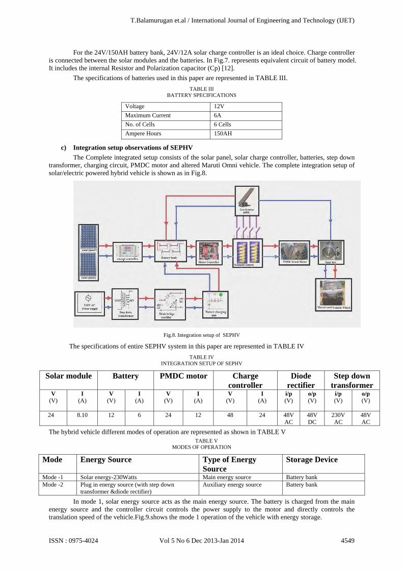
c) Integration setup observations of SEPHV
The Complete integrated setup consists of the solar panel, solar charge controller, batteries, step down transformer, charging circuit, PMDC motor and altered Maruti Omni vehicle. The complete integration setup of solar/electric powered hybrid vehicle is shown as in Fig.8.
Fig.8. Integration setup of SEPHV
The specifications of entire SEPHV system in this paper are represented in TABLE IV TABLE IV
INTEGRATION SETUP OF SEPHV
Solar module Battery PMDC motor Charge controller
Diode rectifier
Step down transformer
V (V)
I (A)
V (V)
I (A)
V (V)
I (A)
V (V)
I (A)
i/p (V)
o/p (V)
i/p (V)
o/p (V)
24
8.10 12 6 24 12 48 24 48V AC
48V DC
230V AC
48V AC
The hybrid vehicle different modes of operation are represented as shown in TABLE V TABLE V
MODES OF OPERATION
Mode Energy Source Type of Energy Source
Storage Device
Mode -1 Solar energy-230Watts Main energy source Battery bank Mode -2 Plug in energy source (with step down
transformer &diode rectifier) Auxiliary energy source Battery bank
In mode 1, solar energy source acts as the main energy source. The battery is charged from the main energy source and the controller circuit controls the power supply to the motor and directly controls the translation speed of the vehicle.Fig.9.shows the mode 1 operation of the vehicle with energy storage.
T.Balamurugan et.al / International Journal of Engineering and Technology (IJET)
ISSN : 0975-4024 Vol 5 No 6 Dec 2013-Jan 2014 4549
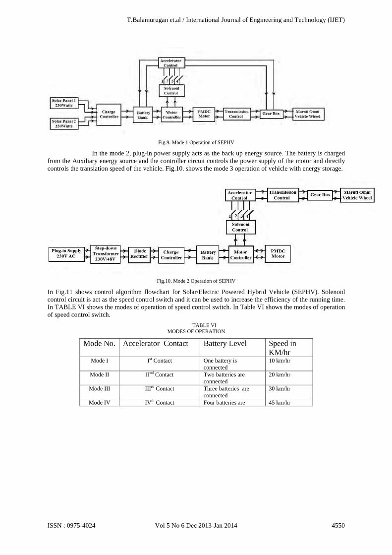
Fig.9. Mode 1 Operation of SEPHV
In the mode 2, plug-in power supply acts as the back up energy source. The battery is charged from the Auxiliary energy source and the controller circuit controls the power supply of the motor and directly controls the translation speed of the vehicle. Fig.10. shows the mode 3 operation of vehicle with energy storage.
Fig.10. Mode 2 Operation of SEPHV
In Fig.11 shows control algorithm flowchart for Solar/Electric Powered Hybrid Vehicle (SEPHV). Solenoid control circuit is act as the speed control switch and it can be used to increase the efficiency of the running time. In TABLE VI shows the modes of operation of speed control switch. In Table VI shows the modes of operation of speed control switch.
TABLE VI MODES OF OPERATION
Mode No. Accelerator Contact Battery Level Speed in KM/hr
Mode I Ist Contact One battery is connected
10 km/hr
Mode II IInd Contact Two batteries are connected
20 km/hr
Mode III IIIrd Contact Three batteries are connected
30 km/hr
Mode IV IVth Contact Four batteries are 45 km/hr
T.Balamurugan et.al / International Journal of Engineering and Technology (IJET)
ISSN : 0975-4024 Vol 5 No 6 Dec 2013-Jan 2014 4550
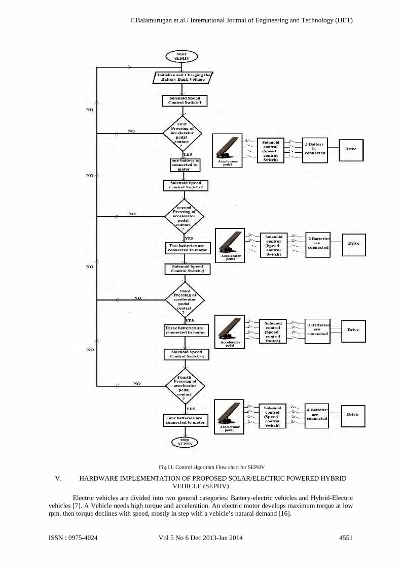
Fig.11. Control algorithm Flow chart for SEPHV
V. HARDWARE IMPLEMENTATION OF PROPOSED SOLAR/ELECTRIC POWERED HYBRID VEHICLE (SEPHV)
Electric vehicles are divided into two general categories: Battery-electric vehicles and Hybrid-Electric vehicles [7]. A Vehicle needs high torque and acceleration. An electric motor develops maximum torque at low rpm, then torque declines with speed, mostly in step with a vehicle’s natural demand [16].
T.Balamurugan et.al / International Journal of Engineering and Technology (IJET)
ISSN : 0975-4024 Vol 5 No 6 Dec 2013-Jan 2014 4551
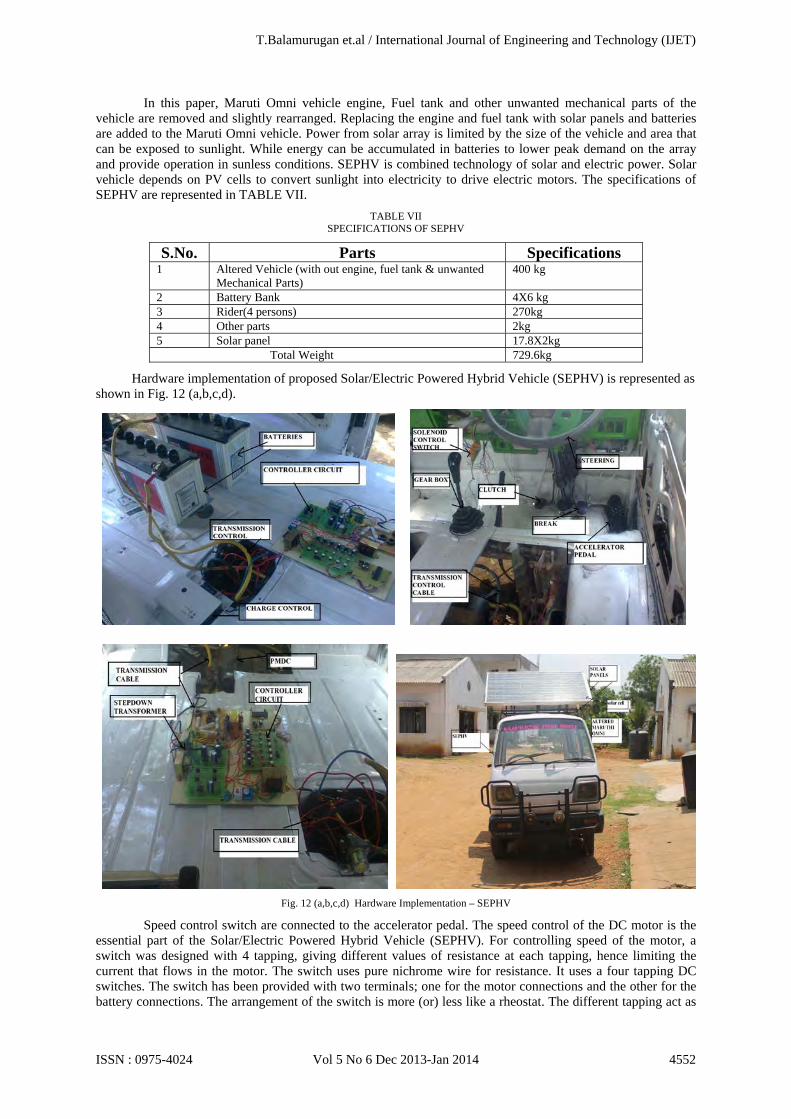
In this paper, Maruti Omni vehicle engine, Fuel tank and other unwanted mechanical parts of the vehicle are removed and slightly rearranged. Replacing the engine and fuel tank with solar panels and batteries are added to the Maruti Omni vehicle. Power from solar array is limited by the size of the vehicle and area that can be exposed to sunlight. While energy can be accumulated in batteries to lower peak demand on the array and provide operation in sunless conditions. SEPHV is combined technology of solar and electric power. Solar vehicle depends on PV cells to convert sunlight into electricity to drive electric motors. The specifications of SEPHV are represented in TABLE VII.
TABLE VII SPECIFICATIONS OF SEPHV
S.No. Parts Specifications 1 Altered Vehicle (with out engine, fuel tank & unwanted
Mechanical Parts) 400 kg
2 Battery Bank 4X6 kg 3 Rider(4 persons) 270kg 4 Other parts 2kg 5 Solar panel 17.8X2kg Total Weight 729.6kg
Hardware implementation of proposed Solar/Electric Powered Hybrid Vehicle (SEPHV) is represented as shown in Fig. 12 (a,b,c,d).
Fig. 12 (a,b,c,d) Hardware Implementation – SEPHV
Speed control switch are connected to the accelerator pedal. The speed control of the DC motor is the essential part of the Solar/Electric Powered Hybrid Vehicle (SEPHV). For controlling speed of the motor, a switch was designed with 4 tapping, giving different values of resistance at each tapping, hence limiting the current that flows in the motor. The switch uses pure nichrome wire for resistance. It uses a four tapping DC switches. The switch has been provided with two terminals; one for the motor connections and the other for the battery connections. The arrangement of the switch is more (or) less like a rheostat. The different tapping act as
T.Balamurugan et.al / International Journal of Engineering and Technology (IJET)
ISSN : 0975-4024 Vol 5 No 6 Dec 2013-Jan 2014 4552
resistance points. With each increase in tapping valve, the valve of resistance decrease, thus at the last tapping the motor will run at the highest speed as the limiting resistance will be minimum whereas the high torque condition of the motor will arise when the minimum tapping will be used. Since the limiting resistance will be maximum.
Fig. 13. Comparison between the energy Consumption in Fuel Vehicle Over SEPHV
Fig. 14. Comparison between the Emission of Maruti Omni Over SEPHV
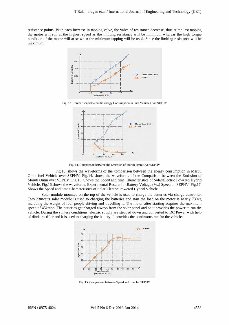
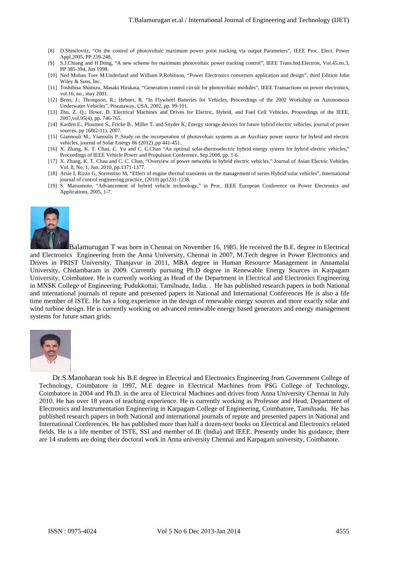
Fig.13. shows the waveforms of the comparison between the energy consumption in Maruti Omni fuel Vehicle over SEPHV. Fig.14. shows the waveforms of the Comparison between the Emission of Maruti Omni over SEPHV. Fig.15. Shows the Speed and time Characteristics of Solar/Electric Powered Hybrid Vehicle. Fig.16.shows the waveforms Experimental Results for Battery Voltage (Vs.) Speed on SEPHV. Fig.17. Shows the Speed and time Characteristics of Solar/Electric Powered Hybrid Vehicle.
Solar module mounted on the top of the vehicle is used to charge the batteries via charge controller. Two 230watts solar module is used to charging the batteries and start the load on the motor is nearly 730kg including the weight of four people driving and travelling it. The motor after starting acquires the maximum speed of 45kmph. The batteries get charged always from the solar panel and so it provides the power to run the vehicle. During the sunless conditions, electric supply are stepped down and converted to DC Power with help of diode rectifier and it is used to charging the battery. It provides the continuous run for the vehicle.
Fig. 15. Comparison between Speed and time for SEPHV
T.Balamurugan et.al / International Journal of Engineering and Technology (IJET)
ISSN : 0975-4024 Vol 5 No 6 Dec 2013-Jan 2014 4553
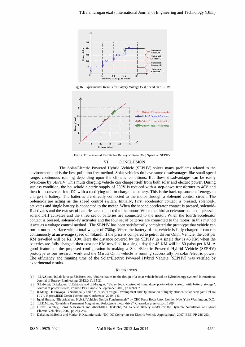
Fig.16. Experimental Results for Battery Voltage (Vs) Speed on SEPHV.
Fig.17. Experimental Results for Battery Voltage (Vs.) Speed on SEPHV.
VI. CONCLUSION The Solar/Electric Powered Hybrid Vehicle (SEPHV) solves many problems related to the
environment and is the best pollution free method. Solar vehicles do have some disadvantages like small speed range, continuous running depending upon the climatic conditions. But these disadvantages can be easily overcome by SEPHV. This multi charging vehicle can charge itself from both solar and electric power. During sunless condition, the household electric supply of 230V is reduced with a step-down transformer to 48V and then it is converted it to DC with a rectifying unit to charge the battery. This is the back-up source of energy to charge the battery. The batteries are directly connected to the motor through a Solenoid control circuit. The Solenoids are acting as the speed control switch. Initially, First accelerator contact is pressed, solenoid-I activates and single battery is connected to the motor. When the second accelerator contact is pressed, solenoid-II activates and the two set of batteries are connected to the motor. When the third accelerator contact is pressed, solenoid-III activates and the three set of batteries are connected to the motor. When the fourth accelerator contact is pressed, solenoid-IV activates and the four set of batteries are connected to the motor. In this method it acts as a voltage control method. The SEPHV has been satisfactorily completed the prototype that vehicle can run in normal surface with a total weight of 730kg. When the battery of the vehicle is fully charged it can run continuously at an average speed of 45km/h. If the price is compared to petrol driven Omni Vehicle, the cost per KM travelled will be Rs. 3.90. Here the distance covered by the SEPHV in a single day is 45 KM when the batteries are fully charged, then cost per KM travelled in a single day for 45 KM will be 50 paisa per KM. A good feature of the proposed configuration is making a Solar/Electric Powered Hybrid Vehicle (SEPHV) prototype as our research work and the Maruti Omni vehicle is running successfully on solar /electric power. The efficiency and running time of the Solar/Electric Powered Hybrid Vehicle [SEPHV] was verified by experimental results.
REFERENCES [1] M.A.Spina, R.J.de la vega,S.R.Rossi etc, “Source issues on the design of a solar vehicle based on hybrid energy system” International
Journal of Energy Engineering, 2012,2(1): 15-21 [2] S.Lalouni, D.Rekioua, T.Rekioua and E.Matagne, “Fuzzy logic control of standalone photovoltaic system with battery storage”,
Journal of power system, volume 193, Issue 2, 5 September 2009, pp 899-907. [3] R.Mangu, K.Prayaga, B.Nadimpally and S.Nicaise, “Design, Development and Optimization of highly efficient solar cars: gato Del sol
I-IV”, in proc.IEEE Green Technology Conference, 2010, 1-6. [4] Iqbal Husain, “Electrical and Hybrid Vehicles Design Fundamentals” by CRC Press Boca Raton London New York Washington, D.C. [5] T.J.E.Miller, “Brushless Permanent Magnet and Reluctance motor drive”, Clarendon press oxford 1989. [6] Oliver Trembly, Louis A.Dessaint and Abdel-Illah Dekkiche, “A Generic Battery model for the Dynamic Simulation of Hybrid
Electric Vehicles”, 2007, pp.284-289. [7] Dakshina M.Bellur and Marian K.Kazimierczuk, “DC-DC Converters for Electric Vehicle Applications”, 2007 IEEE, PP 286-293.
T.Balamurugan et.al / International Journal of Engineering and Technology (IJET)
ISSN : 0975-4024 Vol 5 No 6 Dec 2013-Jan 2014 4554
[8] D.Shmilovitz, “On the control of photovoltaic maximum power point tracking via output Parameters”, IEEE Proc. Elect. Power Appl.2005, PP 239-248.
[9] S.J.Chiang and H.Dong, “A new scheme for maximum photovoltaic power tracking control”, IEEE Trans.Ind.Electron, Vol.45.no.3, PP 385-394, Jun 1998.
[10] Ned Mohan Tore M.Underland and William P.Robinson, “Power Electronics converters application and design”, third Edition John Wiley & Sons, Inc.
[11] Toshihisa Shimizu, Masaki Hirakata, “Generation control circuit for photovoltaic modules”, IEEE Transactions on power electronics, vol.16, no., may 2001.
[12] Beno, J.; Thompson, R.; Hebner, R. “In Flywheel Batteries for Vehicles, Proceedings of the 2002 Workshop on Autonomous Underwater Vehicles”, Piscataway, USA, 2002, pp. 99-101.
[13] Zhu, Z. Q.; Howe, D. Electrical Machines and Drives for Electric, Hybrid, and Fuel Cell Vehicles, Proceedings of the IEEE, 2007,vol.95(4), pp. 746-765.
[14] Karden E., Ploumen S., Fricke B., Miller T. and Snyder K; Energy storage devices for future hybrid electric vehicles, journal of power sources, pp 168(2-11), 2007.
[15] Giannouli M., Yianoulis P.;Study on the incorporation of photovoltaic systems as an Auxiliary power source for hybrid and electric vehicles, journal of Solar Energy 86 (2012) ,pp 441-451.
[16] X. Zhang, K. T. Chau, C. Yu and C. C.Chan “An optimal solar-thermoelectric hybrid energy system for hybrid electric vehicles,” Proceedings of IEEE Vehicle Power and Propulsion Conference, Sep.2008, pp. 1-6.
[17] X. Zhang, K. T. Chau and C. C. Chan, “Overview of power networks in hybrid electric vehicles,” Journal of Asian Electric Vehicles, Vol. 8, No. 1, Jun. 2010, pp.1371-1377.
[18] Arsie I, Rizzo G, Sorrentino M, “Effect of engine thermal transients on the management of series Hybrid solar vehicles”, International journal of control engineering practice, (2010) pp1231-1238.
[19] S. Matsumoto, “Advancement of hybrid vehicle technology,” in Proc. IEEE European Conference on Power Electronics and Applications, 2005, 1-7.
Balamurugan T was born in Chennai on November 16, 1985. He received the B.E. degree in Electrical and Electronics Engineering from the Anna University, Chennai in 2007, M.Tech degree in Power Electronics and Drives in PRIST University, Thanjavur in 2011, MBA degree in Human Resource Management in Annamalai University, Chidambaram in 2009. Currently pursuing Ph.D degree in Renewable Energy Sources in Karpagam University, Coimbatore. He is currently working as Head of the Department in Electrical and Electronics Engineering in MNSK College of Engineering, Pudukkottai, Tamilnadu, India. . He has published research papers in both National and international journals of repute and presented papers in National and International Conferences He is also a life time member of ISTE. He has a long experience in the design of renewable energy sources and more exactly solar and wind turbine design. He is currently working on advanced renewable energy based generators and energy management systems for future smart grids.
Dr.S.Manoharan took his B.E degree in Electrical and Electronics Engineering from Government College of
Technology, Coimbatore in 1997, M.E degree in Electrical Machines from PSG College of Technology, Coimbatore in 2004 and Ph.D. in the area of Electrical Machines and drives from Anna University Chennai in July 2010. He has over 18 years of teaching experience. He is currently working as Professor and Head, Department of Electronics and Instrumentation Engineering in Karpagam College of Engineering, Coimbatore, Tamilnadu. He has published research papers in both National and international journals of repute and presented papers in National and International Conferences. He has published more than half a dozen-text books on Electrical and Electronics related fields. He is a life member of ISTE, SSI and member of IE (India) and IEEE. Presently under his guidance, there are 14 students are doing their doctoral work in Anna university Chennai and Karpagam university, Coimbatore.
T.Balamurugan et.al / International Journal of Engineering and Technology (IJET)
ISSN : 0975-4024 Vol 5 No 6 Dec 2013-Jan 2014 4555