DESIGN OF SLOTTED RECTANGULAR PATCH ARRAY ANTENNA … · ... 4x1 antenna arrays are designed in...
7
International Research Journal of Engineering and Technology (IRJET) e-ISSN: 2395 -0056 Volume: 03 Issue: 04 | Apr-2016 www.irjet.net p-ISSN: 2395-0072 © 2016, IRJET ISO 9001:2008 Certified Journal Page 114 DESIGN OF SLOTTED RECTANGULAR PATCH ARRAY ANTENNA FOR BIOMEDICAL APPLICATIONS P.Hamsagayathri 1 , P.Sampath 2 , M.Gunavathi 3 , D.Kavitha 4 1, 3, 4 P.G Student, Department of Electronics and Communication Engineering, Bannari Amman Institute of Technology, Sathyamangalam, Erode, Tamilnadu. 2 Professor, Department of Electronics and Communication Engineering, Bannari Amman Institute of Technology, Sathyamangalam, Erode, Tamilnadu ---------------------------------------------------------------------***--------------------------------------------------------------------- Abstract— Breast cancer is one of most common life- threatening diseases among world’s women. Early detection of Breast cancer aids in fast and effective treatment to save life. Mammography, which is currently the most popular method of breast screening, has some limitations. Microstrip antennas are used as alternative in growing medical application. The primary objective of the project is to design a simple and cost effective conformal Micro strip Patch Antenna with dimensions of 37 mm X 28 mm using FR4 substrate for operating frequency 2.45 GHz. For enhancing the bandwidth, directivity and gain, 4x1 antenna arrays are designed in linear with corporate feeding networks. Experimental results of proposed antenna are simulated and discussed using the ADS simulation software. The proposed antenna has a bandwidth of 65 MHz covering the frequency range 2.41-2.49 GHz, the return loss below -26 dB and antenna gain of 2.45 dB. The flexible patch antenna holds good efficiency of 87.1%. This paper proposes design patch antenna can be applied for early Breast tumor detection in women. Keywords—Dielectric constant, return loss,Gain, Bandwidth, Patch antenna, Mammography. 1. INTRODUCTION Over the last few years, a significant growth of research involving the use of microwaves to image the human body and many researches are ongoing to the use of microwaves for breast cancer diagnosis. Breast cancer is one of the most life-threatening tumors among the female population. Early diagnosis of cancer is a key factor in providing long- term survival of breast cancer patients. The X-ray mammography is commonly used diagnostic technique for breast tumors detection in Women. However, ionization effects cause health hazard, while breast compression induce considerable discomfort in patients. Tumors located close to the chest wall or underarm result in false negatives. As per World Health Organization (WHO), Mammography has 20% False-negative and 12% False- positive rate. The limitations of X-ray mammography have motivated to develop the microstrip patch antenna as alternate tool for breast cancer detection. This technology leverages the contrast between the dielectric properties of benign and malignant tissues at microwave frequencies to identify the presence and location of significant scatters. The microwave breast imaging technique works on the principle where the signal is scattered by an object when the object is illuminated under an electromagnetic signal. The scattering parameters of the signal depend on various factors like signal strength, material properties of the object and so on. For a given signal source and the environment, the scattered signals depend on the electrical properties of the object, especially dielectric and conductivity. Thistechnique is used to detect the tumor in the breast using microwave signals. The breast tumors have very distinct electrical properties with higher dielectric permittivity and higher conductivity, which allows them to detect by analyzing the scattered signals. Breast tumor cells scatter more signal than the normal breast tissues, which can be received by a separate antenna. The scattering properties of the transmitting antenna changes due to the scattered signals and it can be analyzed and utilized for the tumor detection. 2. LITERATURE SURVEY Prior to design the flexible patch antenna for Breast cancer detection, it is important to understand the existing methodologies and its issues. Mahalakshmi et al (2012) explains the need and working principle of microwave imaging technique. Current methodologies to detect breast cancer are X-ray mammography, ultrasound, tomography and MRI. All these methods have some negative and undesired side effects. Also, these methods are not preferred for younger women because of ionized radiation. So, microwave imaging techniques are used for early diagnosis of Breast cancer detection. Microwave imaging has many advantages such as low cost, less weight, more safety and easier availability. The microwave imaging techniques are designed based on the dielectric contrast between the tumor tissues and the healthy ones. The Sanpanich et al (2011) proposes the electrical properties like conductivity, permittivity or dielectric
-
Upload
phungthien -
Category
Documents
-
view
237 -
download
5
Transcript of DESIGN OF SLOTTED RECTANGULAR PATCH ARRAY ANTENNA … · ... 4x1 antenna arrays are designed in...
International Research Journal of Engineering and Technology (IRJET) e-ISSN: 2395 -0056
Volume: 03 Issue: 04 | Apr-2016 www.irjet.net p-ISSN: 2395-0072
© 2016, IRJET ISO 9001:2008 Certified Journal Page 114
DESIGN OF SLOTTED RECTANGULAR PATCH ARRAY ANTENNA FOR
BIOMEDICAL APPLICATIONS
P.Hamsagayathri1, P.Sampath2, M.Gunavathi3, D.Kavitha4
1, 3, 4 P.G Student, Department of Electronics and Communication Engineering, Bannari Amman Institute of
Technology, Sathyamangalam, Erode, Tamilnadu.
2Professor, Department of Electronics and Communication Engineering, Bannari Amman Institute of Technology, Sathyamangalam, Erode, Tamilnadu
---------------------------------------------------------------------***---------------------------------------------------------------------
Abstract— Breast cancer is one of most common life-threatening diseases among world’s women. Early detection of Breast cancer aids in fast and effective treatment to save life. Mammography, which is currently the most popular method of breast screening, has some limitations. Microstrip antennas are used as alternative in growing medical application. The primary objective of the project is to design a simple and cost effective conformal Micro strip Patch Antenna with dimensions of 37 mm X 28 mm using FR4 substrate for operating frequency 2.45 GHz. For enhancing the bandwidth, directivity and gain, 4x1 antenna arrays are designed in linear with corporate feeding networks. Experimental results of proposed antenna are simulated and discussed using the ADS simulation software. The proposed antenna has a bandwidth of 65 MHz covering the frequency range 2.41-2.49 GHz, the return loss below -26 dB and antenna gain of 2.45 dB. The flexible patch antenna holds good efficiency of 87.1%. This paper proposes design patch antenna can be applied for early Breast tumor detection in women. Keywords—Dielectric constant, return loss,Gain, Bandwidth, Patch antenna, Mammography.
1. INTRODUCTION
Over the last few years, a significant growth of research involving the use of microwaves to image the human body and many researches are ongoing to the use of microwaves for breast cancer diagnosis. Breast cancer is one of the most life-threatening tumors among the female population. Early diagnosis of cancer is a key factor in providing long-term survival of breast cancer patients. The X-ray mammography is commonly used diagnostic technique for breast tumors detection in Women. However, ionization effects cause health hazard, while breast compression induce considerable discomfort in patients. Tumors located close to the chest wall or underarm result in false negatives. As per World Health Organization (WHO), Mammography has 20% False-negative and 12% False-positive rate. The limitations of X-ray mammography have motivated to develop the microstrip patch antenna as alternate tool for breast cancer detection.
This technology leverages the contrast between the dielectric properties of benign and malignant tissues at microwave frequencies to identify the presence and
location of significant scatters. The microwave breast imaging technique works on the principle where the signal is scattered by an object when the object is illuminated under an electromagnetic signal. The scattering parameters of the signal depend on various factors like signal strength, material properties of the object and so on. For a given signal source and the environment, the scattered signals depend on the electrical properties of the object, especially dielectric and conductivity. Thistechnique is used to detect the tumor in the breast using microwave signals. The breast tumors have very distinct electrical properties with higher dielectric permittivity and higher conductivity, which allows them to detect by analyzing the scattered signals. Breast tumor cells scatter more signal than the normal breast tissues, which can be received by a separate antenna. The scattering properties of the transmitting antenna changes due to the scattered signals and it can be analyzed and utilized for the tumor detection.
2. LITERATURE SURVEY
Prior to design the flexible patch antenna for Breast cancer detection, it is important to understand the existing methodologies and its issues.
Mahalakshmi et al (2012) explains the need and working principle of microwave imaging technique. Current methodologies to detect breast cancer are X-ray mammography, ultrasound, tomography and MRI. All these methods have some negative and undesired side effects. Also, these methods are not preferred for younger women because of ionized radiation. So, microwave imaging techniques are used for early diagnosis of Breast cancer detection. Microwave imaging has many advantages such as low cost, less weight, more safety and easier availability. The microwave imaging techniques are designed based on the dielectric contrast between the tumor tissues and the healthy ones.
The Sanpanich et al (2011) proposes the electrical properties like conductivity, permittivity or dielectric

International Research Journal of Engineering and Technology (IRJET) e-ISSN: 2395 -0056
Volume: 03 Issue: 04 | Apr-2016 www.irjet.net p-ISSN: 2395-0072
© 2016, IRJET ISO 9001:2008 Certified Journal Page 115
parameters are used to pathological identify between normal breast cell and malignant tumor tissue with dielectric contrast distribution maps.
S. m. Latif, et al (2014) focuses the design of antenna on fixed substrate. Planar printed monopole antennas have been recently considered for breast cancer imaging due to their simple structure, broad bandwidth, small size, and ease of fabrication. However these antennas are not flexible but bulky. To date, different flexible antennas have been designed for different parts of the body by taking into account the effects of biological tissues for the Industrial Scientific and Medical (ISM) and Med-Radio bands.
H. Bahrami et al (2015) suggests two different antenna design like planar m0onopole (single-polarization) and spiral (dual-polarization) antennas which is light weight to be placed on the breast comfortably. The proposed antenna has minimum reflection coefficient below -10 dB and operate in a frequency range of 2–4 GHz.
3. MICROSTRIP PATCH ANTENNA
The basic structure of a Microstrip Patch antenna comprises of a metallic radiating patch element on the grounded dielectric substrate. The conducting patch of microstrip antenna can be of any geometrical form among which rectangular and circular are the most common.
The Rectangular Microstrip Patch antennas are used as simple and for the extensive and used in many demanding applications. The Rectangular Microstrip Patch antenna with slots and ground plane structure has been proposed. The Microstrip Rectangular patch antenna with microstrip line feed is designed for center frequency of 2.45 GHz for Biomedical application has been presented here and electrical parameters like S11 response, directivity, gain, radiation efficiency are investigated.
Figure-1:Microstrip Patch antenna
Advantages and Disadvantages
The main advantages of patch antenna are given below:
• Light weight and less volume • Minimum fabrication cost • Dual and triple frequency band operations are
possible. Microstrip patch antennas have number of disadvantages as compared to other conventional antennas. The major disadvantages are
• Bandwidth is narrow.
• Efficiency is low.
• Less Gain
4. MICROSTRIP PATCH ARRAY ANTENNA
Antenna arrays are used to enhance various antenna parameters like bandwidth, directivity, gain, beam width and efficiency. There are a variety of methods to feed the signal into Micro strip patch antennas. The main categories are
Contacting: Radio frequency signal is directly fed to the patch element using metallic feed line.
Non-Contacting: The EM field coupling is used to transfer RF power between the micro strip line and antenna patch element.
5. ANTENNA FEEDING NETWORKS
Micro strip line feed
In this case a metallic strip (feed line), which has smaller width as compared to the patch is directly connected to the Micro strip patch. The advantage of this type of feeding technique is that, the feed line can be etched on the same substrate plane and it provides a planar structure.
Micro strip Pin Feed
In this case the coaxial connector is used to feed the RF power to the patch element. The coaxial connector consists of an inner conductor and an outer conductor. The inner conductor is drilled through the substrate plate and is soldered to the metallic patch element. The outer conductor is connected to the metallic ground plane. The advantage of this feeding technique is that the feed can be placed at any desired location.

International Research Journal of Engineering and Technology (IRJET) e-ISSN: 2395 -0056
Volume: 03 Issue: 04 | Apr-2016 www.irjet.net p-ISSN: 2395-0072
© 2016, IRJET ISO 9001:2008 Certified Journal Page 116
Micro strip Series Feed
In this technique the individual patch elements are connected in series using a transmission line from which the desired proportion of RF energy is coupled into the individual element propagated along the line. Here the input power is feed at the first element. Quarter wavelength transformer method is used in this method.
Corporate Feed
A corporate feed is most widely used feeding techniques to fabricate the antenna arrays. In this case the incident power is equally splitting and distributing to the individual antenna elements. The corporate feeding technique can provide power splits of 2k (where k= 2; 4; 8; 16…..).
Figure-2: Corporate Feed Networks
6. RECTANGULAR PATCH ANTENNA DESIGN
The design procedure of rectangular Microstrip patch antenna has three essential parameters. They are:
Frequencyofoperation (fr)
The resonant frequency of the antenna must be chosen appropriately. The antenna designed should be useful for biomedical systems. The resonant frequency selected for proposed antenna design is 2.45 GHz.
Dielectric constant of the substrate (εr)
The dielectric constant of substrate ( ) material plays
an vital role in the patch antenna design. A substrate with a high dielectric constant reduces the size of theantenna but it alsoaffects theantennaperformance.So,thereisatrade-offbetweendimensionandperformanceof patch antenna where the increase in dimension of substrate decreases the antenna performance.
Step1: Heightofdielectric substrate(h)
Microstrippatchantenna to beused inbiomedical systems,antennashouldnot bebulky.
(5.1)
Where
= Relative Permittivity
= Resonant Frequency
Step 2:CalculationofEffective DielectricCoefficient (εr)
The effective dielectric constantcanbecalculated as
(5.2)
Where
= Relative Permittivity
= Height of the substrate
= Width of the substrate
Step 3:CalculationofEffective Length(Leff)
Theeffectivelengthis
(5.3)
Where
= Effective dielectric constant
Step 4:CalculationofLengthExtension(L)
(5.4)
Step 5:CalculationofactualLengthof Patch (L)
Theactuallengthofradiatingpatchisobtained by
(5.5)
Where
= Effective Length

International Research Journal of Engineering and Technology (IRJET) e-ISSN: 2395 -0056
Volume: 03 Issue: 04 | Apr-2016 www.irjet.net p-ISSN: 2395-0072
© 2016, IRJET ISO 9001:2008 Certified Journal Page 117
= Length Extension
Figure-:3 Patch Design Layout
Figure-4: Rectangular Patch Design
Figure-5: Corporate Feed network
Parameter Specification
Operating Frequency 2.45 GHz
Length of the patch 15 mm
Width of the patch 15 mm
Substrate Height 1.6 mm
Patch Thickness 0.7 mil
Flexible Substrate FR4
Dielectric constant of substrate 4.6
Loss Tangent 0.001
Table 1: Design specification of Patch antenna
6. SIMULATION RESULTS AND DISCUSSION
The proposed antenna is simulated through the simulation tool ADS to evaluate its performance. Various changes have been made to width, length of patch for flexible dielectric substrate with different thickness.
By varying probe feed length, feed position, ground plane, width of the slot and length of the slot, the s-parameter variation is studied. The gain and bandwidth is enhanced for the Rectangular shaped microstrip patch with minimized return loss.
Figure- 6: S11 Response using ADS
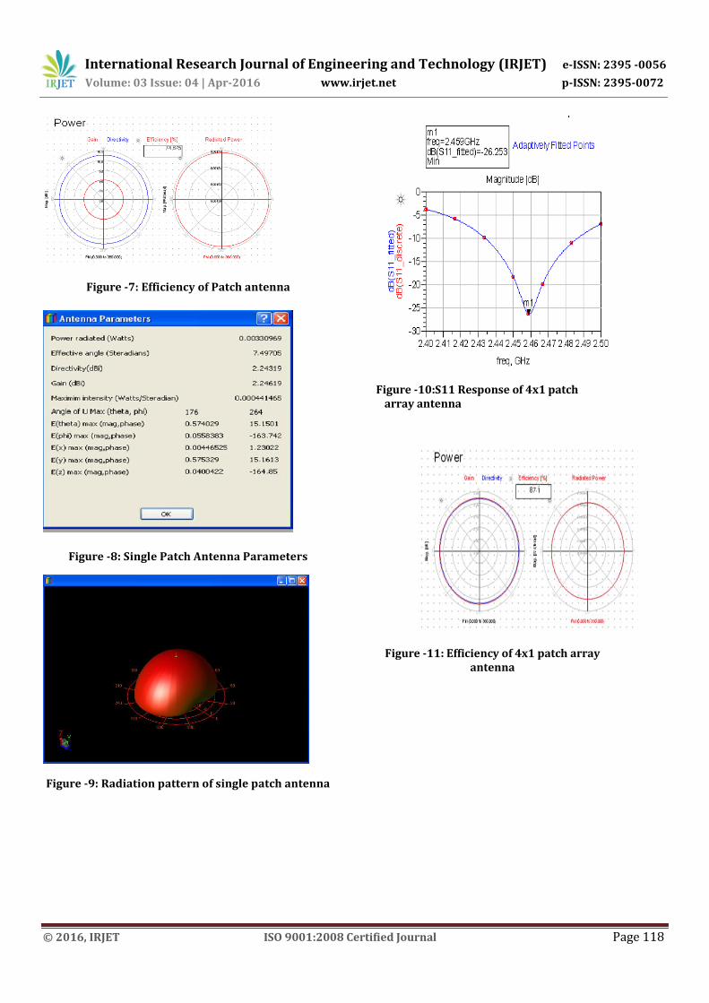
Figure 6 and Figure 10 shows the S11 parameters (return loss) for the proposed antenna. The designed antenna resonates at 2.453GHz. The bandwidth of the simulated patch antenna is 30 MHz and resonant frequency is 2.453GHz (2.439 GHz – 2.467 GHz). Figure 7 displays the efficiency and radiated power of the patch antenna.
International Research Journal of Engineering and Technology (IRJET) e-ISSN: 2395 -0056
Volume: 03 Issue: 04 | Apr-2016 www.irjet.net p-ISSN: 2395-0072
© 2016, IRJET ISO 9001:2008 Certified Journal Page 118
Figure -7: Efficiency of Patch antenna
Figure -8: Single Patch Antenna Parameters
Figure -9: Radiation pattern of single patch antenna
Figure -10:S11 Response of 4x1 patch array antenna
Figure -11: Efficiency of 4x1 patch array antenna

International Research Journal of Engineering and Technology (IRJET) e-ISSN: 2395 -0056
Volume: 03 Issue: 04 | Apr-2016 www.irjet.net p-ISSN: 2395-0072
© 2016, IRJET ISO 9001:2008 Certified Journal Page 119
Figure- 12: Antenna Parameters of 4x1 patch array antenna
Figure -13: Radiation pattern of 4x1 patch array antenna
Table-2: Comparative study of simulated results
Parameters Single Patch
4x1 patch array antenna
Operating Frequency
2.45 GHz 2.45 GHz
Return loss -12 dB -26 dB
Gain 2.24 dBi 9.06 dBi
Directivity 2.24 dBi 10.34 dBi
Efficiency 74% 87%
Bandwidth 30 MHz 65 MHz
7. CONCLUSION
In this paper, single patch and four patches with corporate feed microstrip antenna characteristics are investigated using ADS software. From the analysis, it is observed that the four patch microstrip antenna with corporate feeding is more efficient which gives higher gain and best return loss at the desired frequency range centered at 2.45 GHz. That is as the number of patches increases the performance of the antenna and it can be used for breast cancer detection.
ACKNOWLEDGMENT
I would like to thank authors, mentioned in the references which are citied below for their valuable research works which helped me to gain knowledge. And also I thank my mentors for their precious guidance.
REFERENCES
[1] Constantine A. Balanis “Antenna Theory – Analysis and Design” in Wiley India Edition.
[2] RabiaÇalışkan et al , “A Microstrip Patch Antenna Design for Breast Cancer Detection” - World Conference on Technology, Innovation and Entrepreneurship - Science direct @2015
[3] Younis M. Abbosh, “Breast cancer diagnosis using microwave and hybrid imaging methods” - International Journal of Computer Science & Engineering Survey (IJCSES) Vol.5, No.3, June 2014
[4] N. Mahalakshmi and Vijay Jeyakumar,“Design and Development of Single Layer Microstrip Patch Antenna for Breast Cancer Detection” - Bonfring International Journal of Research in Communication Engineering, Vol. 2, Special Issue 1, July 2014
[5] Pankaj Kumar Singh et al, “Deign & Simulation of Microstrip Antenna for Cancer Diagnosis” in International Journal of Scientific & Engineering Research, Volume 4, Issue 11, November-2013
[6] T.-H. Kim and J.-K. Pack,“Measurement of electrical characteristics of female breast tissues for the development of the breast cancer detector” - Progress In Electromagnetics Research C, Vol. 30, 189{199, 2012
[7] A. Sanpanich et al, “Basic investigation of breast cancer detection in early stage using Microwave Radiation: Finite Element Analysis Approach” in Biomedical Engineering International Conference (BMEiCON-2011),
[8] S. Adnan et al, “Microstrip Antenna for Microwave Imaging Application” - Progress In Electromagnetics Research Symposium

International Research Journal of Engineering and Technology (IRJET) e-ISSN: 2395 -0056
Volume: 03 Issue: 04 | Apr-2016 www.irjet.net p-ISSN: 2395-0072
© 2016, IRJET ISO 9001:2008 Certified Journal Page 120
Proceedings, Marrakesh, Morocco, Mar. 20{23, 2011
[9] Liting Wang et al, “Design of Ultra-Wideband MIMO antenna for breast tumor detection” in International Journal of Antennas and Propagation , 2014.
[10] H. Bahrami et al ,“Flexible 16 Antenna Array for Microwave Breast Cancer Detection” in IEEE Transactions on biomedical engineering, VOL. 62, NO. 10, October 2015.
[11] Liting Wang et al, “Design of Ultra-Wideband MIMO antenna for breast tumor detection” in International Journal of Antennas and Propagation , 2014.
[12] “Emerging Technologies in Breast Cancer Detection” by Andrew P. Smith in www.nic.nih.gov (National cancer institute)