Eye Alignment Clinic / Children's Eye Centre Eye Screening Packages

Design of see-through near-eye display for presbyopia YISHI WU, CHAO PING CHEN,* LEI ZHOU, YANG LI, BING YU, AND HUAYI JIN Smart Display Lab, Department of Electronic Engineering, Shanghai Jiao Tong University, Shanghai, China *[email protected]
Abstract: We propose a compact design of see-through near-eye display that is dedicated to presbyopia. Our solution is characterized by a plano-convex waveguide, which is essentially an integration of a corrective lens and two volume holograms. Its design rules are set forth in detail, followed by the results and discussion regarding the diffraction efficiency, field of view, modulation transfer function, distortion, and simulated imaging. © 2017 Optical Society of America
OCIS codes: (080.2740) Geometric optical design; (090.2820) Heads-up displays; (120.2040) Displays.
References and links 1. Goldman Sachs Global Investment Research, “Virtual & augmented reality: understanding the race for the next
computing platform,” http://www.goldmansachs.com/our-thinking/pages/virtual-and-augmented-reality-report.html.
2. K. Kiyokawa, Y. Kurata, and H. Ohno, “An optical see-through display for mutual occlusion with a real-time stereovision system,” Comput. Graph. 25(5), 765–779 (2001).
3. S. Liu, H. Hua, and D. Cheng, “A novel prototype for an optical see-through head-mounted display with addressable focus cues,” IEEE Trans. Vis. Comput. Graph. 16(3), 381–393 (2010).
4. H.-S. Chen, Y.-J. Wang, P.-J. Chen, and Y.-H. Lin, “Electrically adjustable location of a projected image in augmented reality via a liquid-crystal lens,” Opt. Express 23(22), 28154–28162 (2015).
5. Y. Amitai, S. Reinhorn, and A. A. Friesem, “Visor-display design based on planar holographic optics,” Appl. Opt. 34(8), 1352–1356 (1995).
6. Y. Amitai, “Extremely compact high-performance HMDs based on substrate-guided optical element,” in SID Symposium (2004), pp. 310–313.
7. H. Mukawa, K. Akutsu, I. Matsumura, S. Nakano, T. Yoshida, M. Kuwahara, and K. Aiki, “A full-color eyewear display using planar waveguides with reflection volume holograms,” J. Soc. Inf. Disp. 17(3), 185–193 (2009).
8. D. Cheng, Y. Wang, C. Xu, W. Song, and G. Jin, “Design of an ultra-thin near-eye display with geometrical waveguide and freeform optics,” Opt. Express 22(17), 20705–20719 (2014).
9. N. Zhang, J. Liu, J. Han, X. Li, F. Yang, X. Wang, B. Hu, and Y. Wang, “Improved holographic waveguide display system,” Appl. Opt. 54(12), 3645–3649 (2015).
10. A. Maimone, D. Lanman, K. Rathinavel, K. Keller, D. Luebke, and H. Fuchs, “Pinlight displays: wide field of view augmented reality eyeglasses using defocused point light sources,” ACM Trans. Graph. 33(4), 89 (2014).
11. M. Sugawara, M. Suzuki, and N. Miyauchi, “Retinal imaging laser eyewear with focus-free and augmented reality,” SID Display Week (2016), pp. 164–167.
12. C. P. Chen, Z. Zhang, and X. Yang, “A head-mounted smart display device for augmented reality,” CN Patent 201610075988.7 (2016).
13. L. Zhou, C. P. Chen, Y. Wu, K. Wang, and Z. Zhang, “See-through near-eye displays for visual impairment,” The 23rd International Display Workshops in conjunction with Asia Display (2016), pp. 1114–1115.
14. L. Zhou, C. P. Chen, Y. Wu, Z. Zhang, K. Wang, B. Yu, and Y. Li, “See-through near-eye displays enabling vision correction,” Opt. Express 25(3), 2130–2142 (2017).
15. H. E. Milton, P. B. Morgan, J. H. Clamp, and H. F. Gleeson, “Electronic liquid crystal contact lenses for the correction of presbyopia,” Opt. Express 22(7), 8035–8040 (2014).
16. R. E. Fischer, B. Tadic-Galeb, and P. R. Yoder, Optical System Design 2nd Edition (McGraw-Hill Education, 2008).
17. F. L. Pedrotti, L. M. Pedrotti, and L. S. Pedrotti, Introduction to Optics 3rd Edition (Addison-Wesley, 2006). 18. Wikipedia, “Presbyopia,” https://en.wikipedia.org/wiki/Presbyopia. 19. J. W. Goodman, Introduction to Fourier Optics 3rd Edition (Roberts & Company Publishers, 2004). 20. Y. Xiong, Z. He, C. P. Chen, X. Li, A. Li, Z. Ye, J. Lu, G. He, and Y. Su, “Coherent backlight system for flat-
panel holographic 3D display,” Opt. Commun. 296, 41–46 (2013). 21. C. P. Chen, Y. Su, and C. G. Jhun, “Recent advances in holographic recording media for dynamic holographic
display,” J. Opt. Photonics 1(1), 1–8 (2014).
Vol. 25, No. 8 | 17 Apr 2017 | OPTICS EXPRESS 8937
#287255 https://doi.org/10.1364/OE.25.008937 Journal © 2017 Received 21 Feb 2017; revised 29 Mar 2017; accepted 30 Mar 2017; published 6 Apr 2017
22. Z. He, C. P. Chen, H. Gao, Q. Shi, S. Liu, X. Li, Y. Xiong, J. Lu, G. He, and Y. Su, “Dynamics of peristrophic multiplexing in holographic polymer-dispersed liquid crystal,” Liq. Cryst. 41(5), 673–684 (2014).
23. R. Bräuer and O. Bryngdahl, “Electromagnetic diffraction analysis of two-dimensional gratings,” Opt. Commun. 100(1–4), 1–5 (1993).
24. E. Noponen and J. Turunen, “Eigenmode method for electromagnetic synthesis of diffractive elements with three-dimensional profiles,” J. Opt. Soc. Am. A 11(9), 2494–2502 (1994).
25. L. Li, “New formulation of the Fourier modal method for crossed surface-relief gratings,” J. Opt. Soc. Am. A 14(10), 2758–2767 (1997).
26. C. P. Chen, Y. Li, Y. Su, G. He, J. Lu, and L. Qian, “Transmissive interferometric display with single-layer Fabry-Pérot filter,” J. Disp. Technol. 11(9), 715–719 (2015).
1. Introduction According to a 58-page report released in January 2016 by Goldman Sachs [1], augmented reality (AR) is predicted as a disruptive technology that will impact on a number of industries, ranging from gaming to military. See-through near-eye display (NED), among other things, is one of the key components of AR, as it serves as an interface connecting both real and virtual worlds. Generally, see-through NED can be categorized into three main families―combiner-based [2–4], waveguide-based [5–9], and retinal-projection-based [10,11]. Combiner-based NEDs usually adopt beam splitters [3] or semi-reflective mirrors [2], through which real and virtual images could overlay with each other. Due to the size of beam splitters and semi-reflective mirrors, such NEDs―if designed with a large field of view (FOV)―are often bulky and heavy. Waveguide-based NEDs can be designed with a compact form factor by using planar waveguides [6,7]. However, once the light enters into a waveguide, the maximum angle, at which it could leave, will be confined by the total internal reflection. For this reason, FOVs of those NEDs largely hinge on the types of elements for out-coupling. Retinal-projection-based NEDs can project images directly onto the retina. For example, pinlight display [10], co-developed by University of North Carolina at Chapel Hill and Nvidia, achieved 110° FOV on a very simple structure that merely comprises a plastic substrate with multiple point light sources and a transparent liquid crystal display. But there is an intrinsic problem associated with this retinal-projection-based NED in that the image formed on the retina is subject to the change of eye’s focus.
Unlike other mobile devices, e.g. smartphones, NED is also a wearable device that is close to the eyes. Therefore, optics aside, ergonomics needs to be taken into account as well. One of the ergonomic issues is how to save the visually impaired users from the trouble of wearing extra eyeglasses or contact lens. As an earlier attempt, we introduced a combiner-based NED that enables the vision correction for myopia [12–14]. After being aware of an astonishing fact that for people aged over 50, the chance of having presbyopia is literally 100% [15], we are motivated to find a solution for old people and presbyopia. In this paper, a compact design of see-through NED, highlighted by a plano-convex waveguide and volume holograms, is proposed. In what follows, its structure, design rules and simulation results are to be elaborated.
2. Design principle 2.1 Proposed structure
Figure 1 is the schematic drawing of the proposed monocular see-through NED, which mainly consists of two components, i.e. a pico projector and a plano-convex waveguide. Mounted inside the pico projector are a microdisplay and a 4-element projection lens. On the lower surface of the plano-convex waveguide, there is a volume hologram being attached alongside the pico projector. This volume hologram is capable of coupling the light from the pico projector into the waveguide. On the upper surface of the plano-convex waveguide, there is another volume hologram that is to couple the light out of the waveguide. To avoid being confused with these two volume holograms, the former is referred to as the in-coupling volume hologram or IVH for short, whereas the latter as the out-coupling volume hologram
Vol. 25, No. 8 | 17 Apr 2017 | OPTICS EXPRESS 8938
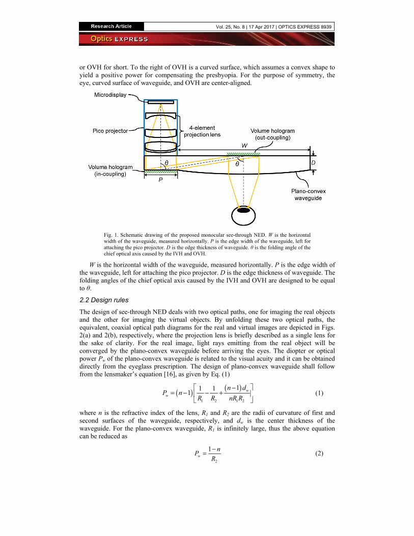
or OVH for short. To the right of OVH is a curved surface, which assumes a convex shape to yield a positive power for compensating the presbyopia. For the purpose of symmetry, the eye, curved surface of waveguide, and OVH are center-aligned.
Fig. 1. Schematic drawing of the proposed monocular see-through NED. W is the horizontal width of the waveguide, measured horizontally. P is the edge width of the waveguide, left for attaching the pico projector. D is the edge thickness of waveguide. θ is the folding angle of the chief optical axis caused by the IVH and OVH.
W is the horizontal width of the waveguide, measured horizontally. P is the edge width of the waveguide, left for attaching the pico projector. D is the edge thickness of waveguide. The folding angles of the chief optical axis caused by the IVH and OVH are designed to be equal to θ.
2.2 Design rules
The design of see-through NED deals with two optical paths, one for imaging the real objects and the other for imaging the virtual objects. By unfolding these two optical paths, the equivalent, coaxial optical path diagrams for the real and virtual images are depicted in Figs. 2(a) and 2(b), respectively, where the projection lens is briefly described as a single lens for the sake of clarity. For the real image, light rays emitting from the real object will be converged by the plano-convex waveguide before arriving the eyes. The diopter or optical power Pw of the plano-convex waveguide is related to the visual acuity and it can be obtained directly from the eyeglass prescription. The design of plano-convex waveguide shall follow from the lensmaker’s equation [16], as given by Eq. (1)
( ) ( )1 2 1 2
11 11 w
w
n dP n
R R nR R
− = − − +
(1)
where n is the refractive index of the lens, R1 and R2 are the radii of curvature of first and second surfaces of the waveguide, respectively, and dw is the center thickness of the waveguide. For the plano-convex waveguide, R1 is infinitely large, thus the above equation can be reduced as
2
1w
nP
R
−= (2)
Vol. 25, No. 8 | 17 Apr 2017 | OPTICS EXPRESS 8939

Fig. 2. Unfolded optical path diagrams for the (a) real and (b) virtual images. The projection lens and plano-convex waveguide are regarded as a convex lens and a plano-convex lens respectively to simplify the light path modeling.
For the virtual image, light rays emitting from the microdisplay are at first converged by the projection lens, forming an intermediate magnified virtual image S′. Then, through the coupling of IVH, light rays enter into the waveguide. When reaching the OVH, light rays are reflected toward the eye. Upon leaving the waveguide, light rays will form a final magnified virtual image S″. s1 is the distance between the microdisplay and projection lens, s′ the distance between the image S′ and projection lens, and Pp is the diopter of projection lens. They could be correlated via the thin-lens equation [17]
1
1 1
' pPs s
+ = (3)
Similarly, we could also have
2
1 1
' " wPs s s
+ =+
(4)
where s′′ is the distance between the image S″ and waveguide, and s2 the distance between the projection lens and waveguide. Combining Eqs. (3) and (4), s′′ can be derived as
Vol. 25, No. 8 | 17 Apr 2017 | OPTICS EXPRESS 8940
1 2 1 2
1 2 1 1 2
"1
p
w w p p w
s s s s Ps
s P s P s P s s P P
− − +=
− − − + + (5)
The lateral magnification M―defined as the ratio of lateral size of S″ to lateral size of microdisplay―is expressed as
( ) 1 2 1 1 21 2
' " 1
1' w w p p w
s sM
s P s P s P s s P Ps s s= =
− − − + ++ (6)
2.3 Field of view
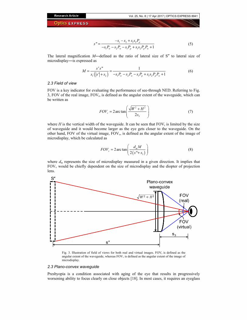
FOV is a key indicator for evaluating the performance of see-through NED. Referring to Fig. 3, FOV of the real image, FOVr, is defined as the angular extent of the waveguide, which can be written as
2 2
3
2arc tan2r
W HFOV
s
+ =
(7)
where H is the vertical width of the waveguide. It can be seen that FOVr is limited by the size of waveguide and it would become larger as the eye gets closer to the waveguide. On the other hand, FOV of the virtual image, FOVv, is defined as the angular extent of the image of microdisplay, which be calculated as
( )3
2arc tan2 "
mv
d MFOV
s s
= +
(8)
where dm represents the size of microdisplay measured in a given direction. It implies that FOVv would be chiefly dependent on the size of microdisplay and the diopter of projection lens.
Fig. 3. Illustration of field of views for both real and virtual images. FOVr is defined as the angular extent of the waveguide, whereas FOVv is defined as the angular extent of the image of microdisplay.
2.3 Plano-convex waveguide
Presbyopia is a condition associated with aging of the eye that results in progressively worsening ability to focus clearly on close objects [18]. In most cases, it requires an eyeglass
Vol. 25, No. 8 | 17 Apr 2017 | OPTICS EXPRESS 8941
with a positive diopter between 1 and 2 [15]. Consider a case that the user has only 2 diopters of presbyopia. The material of lens is chosen as the polycarbonate. Following the above design rules, a plano-convex waveguide can be designed with the parameters listed in Table 1.
Table 1. Design parameters for the plano-convex waveguide
Object Parameter Value
Polycarbonate n@532 nm 1.5917
plano-convex waveguide
diopter + 2 m−1
W 4.4 cm
P 1.1 cm
D 2 mm
R1 ∞ m
R2 −0.2959 m
2.4 Projection lens
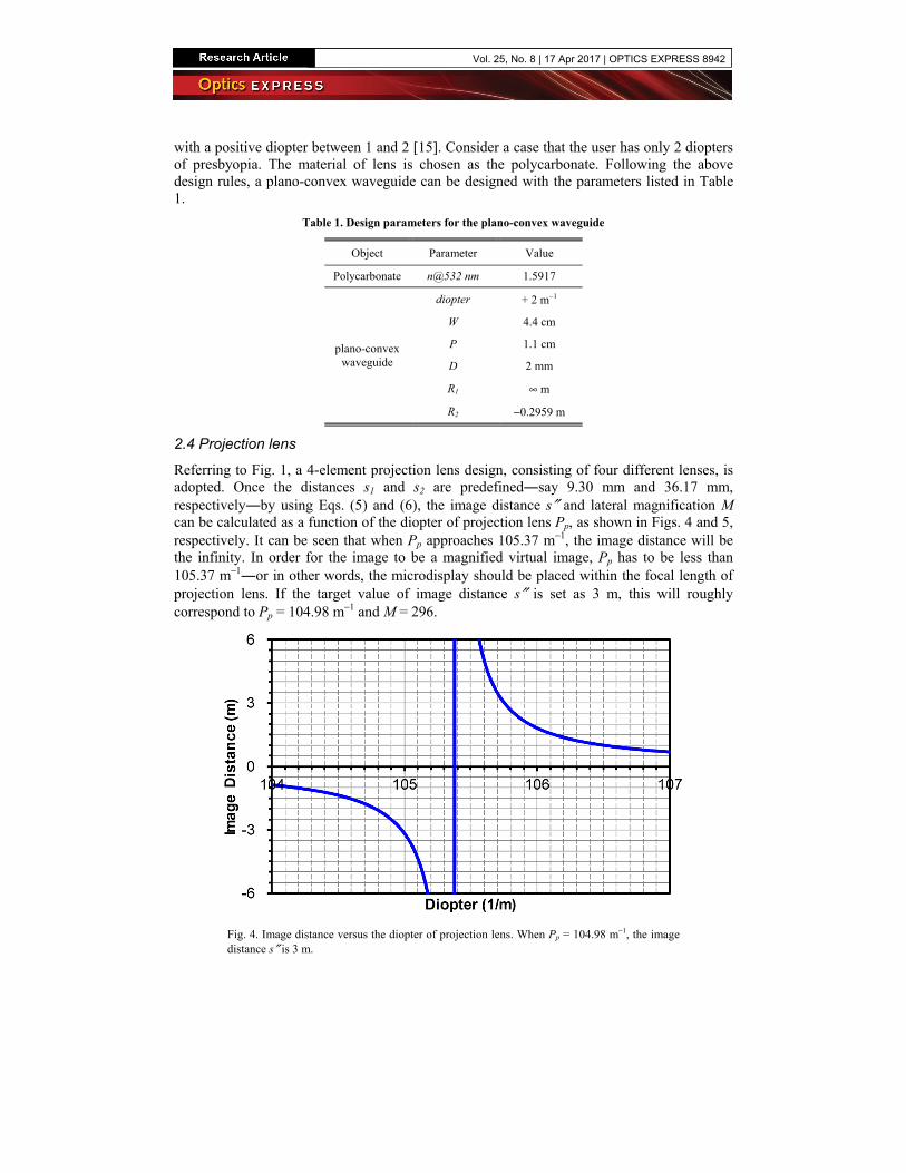
Referring to Fig. 1, a 4-element projection lens design, consisting of four different lenses, is adopted. Once the distances s1 and s2 are predefined―say 9.30 mm and 36.17 mm, respectively―by using Eqs. (5) and (6), the image distance s″ and lateral magnification M can be calculated as a function of the diopter of projection lens Pp, as shown in Figs. 4 and 5, respectively. It can be seen that when Pp approaches 105.37 m−1, the image distance will be the infinity. In order for the image to be a magnified virtual image, Pp has to be less than 105.37 m−1―or in other words, the microdisplay should be placed within the focal length of projection lens. If the target value of image distance s″ is set as 3 m, this will roughly correspond to Pp = 104.98 m−1 and M = 296.
Fig. 4. Image distance versus the diopter of projection lens. When Pp = 104.98 m−1, the image distance s″ is 3 m.
Vol. 25, No. 8 | 17 Apr 2017 | OPTICS EXPRESS 8942

Fig. 5. Lateral magnification versus the diopter of projection lens. When Pp = 104.98 m−1, the lateral magnification M is 296.
2.5 Volume hologram
Volume hologram, also known as thick hologram, is a hologram or grating whose thickness is way larger than the vacuum wavelength of the light used during reconstruction [19]. It can be either phase-type or amplitude-type, depending on the recording materials. The common materials used for recording the phase-type hologram are the holographic polymer-dispersed liquid crystal [20] and photopolymer [21]. Being operated under Bragg’s condition for certain wavelengths and incident angles, a phase-type volume hologram could have a diffraction efficiency (DE) as high as 100% [19]. The design of volume hologram shall follow from the Bragg’s law [19], which is expressed as
sin2B
mλθ =Λ
(9)
where θB denotes the Bragg angle, m is a positive integer, λ is the incident wavelength in the free space, and Λ is the period of hologram. For our NED, the advantage of using volume holograms for folding or relaying the light is that the waveguide can be made as thin as possible, thereby reducing the weight and the room it needs to be disposed. Plus, compared to other types of grating, e.g. blazed grating [17], different volume holograms can be easily stacked or multiplexed, which is necessary for broadening the spectral and angular bandwidth [22]. More importantly, by bypassing the total internal reflection via directly relaying the light from IVH to OVH, the limitation of the total internal reflection can be lifted.
3. Results and discussion 3.1 Simulation settings
Our simulation is implemented with the softwares Code V (Synopsys) and VirtualLab Fusion (Wyrowski Photonics). The former, based on the ray tracing [16], is capable of analyzing the imaging properties, including modulation transfer function (MTF), distortion, and imaging simulation. The latter, based on the Fourier modal method [23–25], is used to calculate the DE of volume holograms. The design wavelength is 532 nm.
The numbering of surfaces is labelled in Fig. 6. A 0.47″ (11.94 mm) microdisplay with an aspect ratio of 16:9 is employed. The object represents the microdisplay. Surfaces 1 to 7 comprise the 4-element projection lens. Surfaces 8 to 9 comprise the waveguide. According to the design rules mentioned above, we could create an initial structure by presetting the parameters for each element. Then, an optimization, whose error function type is set as transverse ray aberration [16], is carried out by constraining the effective focal length of the
Vol. 25, No. 8 | 17 Apr 2017 | OPTICS EXPRESS 8943
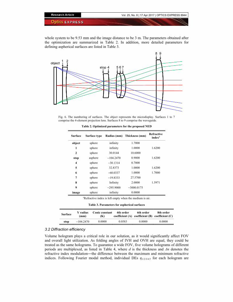
whole system to be 9.53 mm and the image distance to be 3 m. The parameters obtained after the optimization are summarized in Table 2. In addition, more detailed parameters for defining aspherical surfaces are listed in Table 3.
Fig. 6. The numbering of surfaces. The object represents the microdisplay. Surfaces 1 to 7 comprise the 4-element projection lens. Surfaces 8 to 9 comprise the waveguide.
Table 2. Optimized parameters for the proposed NED
Surface Surface type Radius (mm) Thickness (mm)Refractive
indexa
object sphere infinity 1.7000
1 sphere infinity 1.0000 1.6200
2 sphere 30.0144 10.6000
stop asphere −104.2470 0.9000 1.6200
4 sphere −30.1314 0.7000
5 sphere 32.8373 1.0000 1.6200
6 sphere −60.0337 1.0000 1.7000
7 sphere −19.8333 27.5700
8 sphere Infinity 2.0000 1.5971
9 sphere −295.9000 −3000.0175
image sphere infinity 0.0000
aRefractive index is left empty when the medium is air.
Table 3. Parameters for aspherical surfaces
Surface Y radius
(mm) Conic constant
(K) 4th order
coefficient (A)6th order
coefficient (B)8th order
coefficient (C)
stop −104.2470 0.0000 0.0583 0.0000 0.0000
3.2 Diffraction efficiency
Volume hologram plays a critical role in our solution, as it would significantly affect FOV and overall light utilization. As folding angles of IVH and OVH are equal, they could be treated as the same holograms. To guarantee a wide FOV, five volume holograms of different periods are multiplexed, as listed in Table 4, where d is the thickness and Δn denotes the refractive index modulation―the difference between the maximum and minimum refractive indices. Following Fourier modal method, individual DEs η1/2/3/4/5 for each hologram are
Vol. 25, No. 8 | 17 Apr 2017 | OPTICS EXPRESS 8944
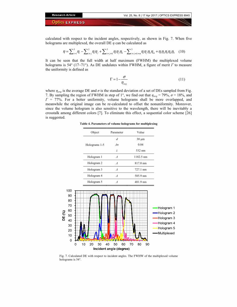
calculated with respect to the incident angles, respectively, as shown in Fig. 7. When five holograms are multiplexed, the overall DE η can be calculated as
5 5 5 5
1 2 3 4 51 i i j i j k i j k mi i j i j k i j k mη η ηη ηη η ηη η η η η η η η
= ≠ ≠ ≠ ≠ ≠ ≠= − + − + (10)
It can be seen that the full width at half maximum (FWHM) the multiplexed volume holograms is 54° (17~71°). As DE undulates within FWHM, a figure of merit Γ to measure the uniformity is defined as
1avg
ση
Γ = − (11)
where ηavg is the average DE and σ is the standard deviation of a set of DEs sampled from Fig. 7. By sampling the region of FWHM in step of 1°, we find out that ηavg = 79%, σ = 18%, and Γ = 77%. For a better uniformity, volume holograms shall be more overlapped, and meanwhile the original image can be re-calculated to offset the nonuniformity. Moreover, since the volume hologram is also sensitive to the wavelength, there will be inevitably a crosstalk among different colors [7]. To eliminate this effect, a sequential color scheme [26] is suggested.
Table 4. Parameters of volume holograms for multiplexing
Object Parameter Value
Holograms 1-5
d 30 μm
Δn 0.04
λ 532 nm
Hologram 1 Λ 1182.5 nm
Hologram 2 Λ 817.0 nm
Hologram 3 Λ 727.1 nm
Hologram 4 Λ 585.9 nm
Hologram 5 Λ 481.9 nm
Fig. 7. Calculated DE with respect to incident angles. The FWHW of the multiplexed volume holograms is 54°.
Vol. 25, No. 8 | 17 Apr 2017 | OPTICS EXPRESS 8945
3.3 Field of view
Table 5 lists the parameters necessary for evaluating FOV, in which H stands for the vertical dimension of the waveguide, and s′′ and s3 are chosen as 3 m and 1.0 cm, respectively. In fact, both s′′ and s3 can be adjustable. Using Eqs. (7) and (8), FOVr and FOVv are calculated as 137° and 61°, both measured diagonally. Incidentally, in order for FOV not to be potentially blocked by the pico projector, it is recommended to place the pico projector at the upper forehead.
Table 5. Parameters for calculating FOV
Object Parameter Value
FOVr
W 4.4 cm
H 2.5 cm
s3 1.0 cm
FOVv
dm (diagonal) 0.47 inch
s′′ 3 m
M 296
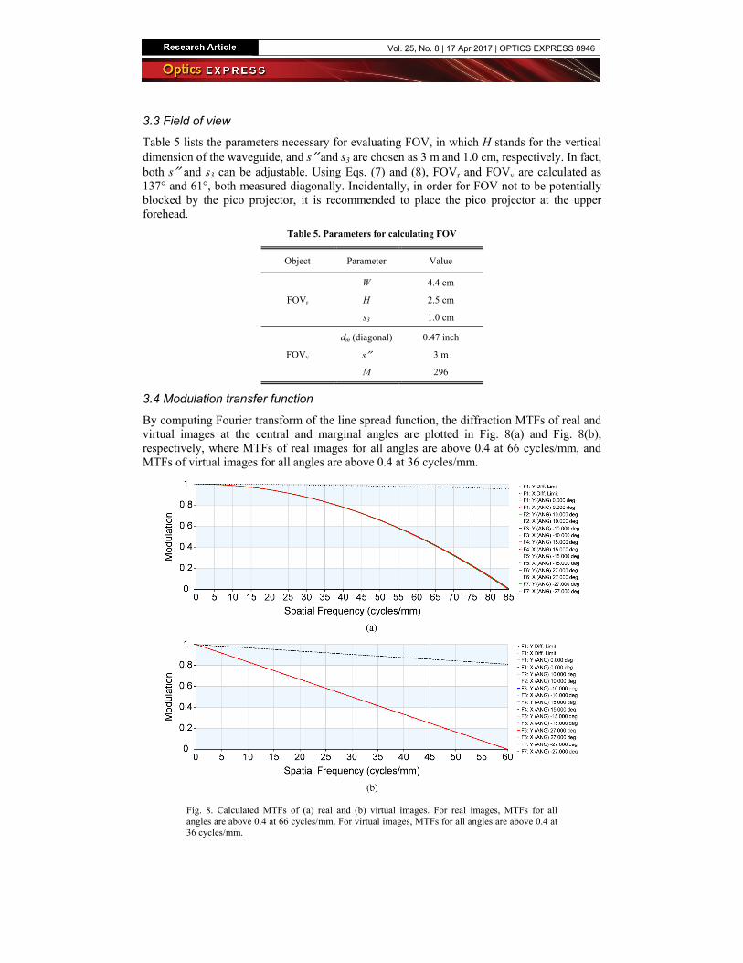
3.4 Modulation transfer function
By computing Fourier transform of the line spread function, the diffraction MTFs of real and virtual images at the central and marginal angles are plotted in Fig. 8(a) and Fig. 8(b), respectively, where MTFs of real images for all angles are above 0.4 at 66 cycles/mm, and MTFs of virtual images for all angles are above 0.4 at 36 cycles/mm.
Fig. 8. Calculated MTFs of (a) real and (b) virtual images. For real images, MTFs for all angles are above 0.4 at 66 cycles/mm. For virtual images, MTFs for all angles are above 0.4 at 36 cycles/mm.
Vol. 25, No. 8 | 17 Apr 2017 | OPTICS EXPRESS 8946
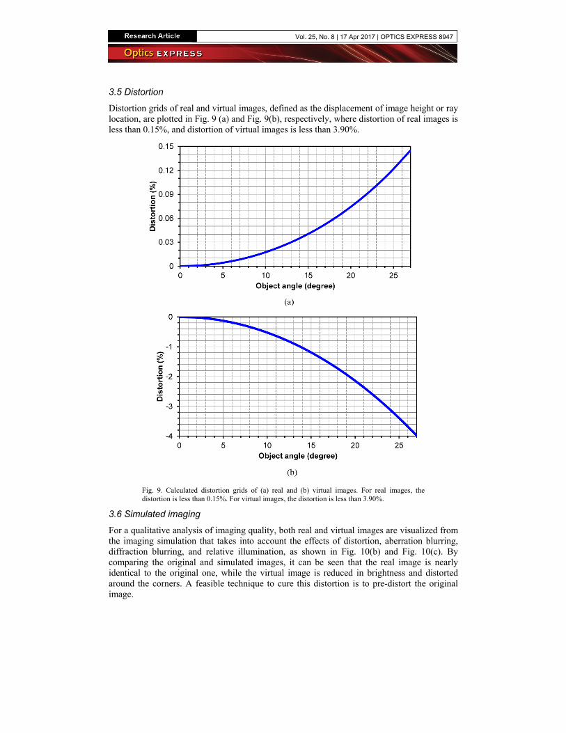
3.5 Distortion
Distortion grids of real and virtual images, defined as the displacement of image height or ray location, are plotted in Fig. 9 (a) and Fig. 9(b), respectively, where distortion of real images is less than 0.15%, and distortion of virtual images is less than 3.90%.
Fig. 9. Calculated distortion grids of (a) real and (b) virtual images. For real images, the distortion is less than 0.15%. For virtual images, the distortion is less than 3.90%.
3.6 Simulated imaging
For a qualitative analysis of imaging quality, both real and virtual images are visualized from the imaging simulation that takes into account the effects of distortion, aberration blurring, diffraction blurring, and relative illumination, as shown in Fig. 10(b) and Fig. 10(c). By comparing the original and simulated images, it can be seen that the real image is nearly identical to the original one, while the virtual image is reduced in brightness and distorted around the corners. A feasible technique to cure this distortion is to pre-distort the original image.
Vol. 25, No. 8 | 17 Apr 2017 | OPTICS EXPRESS 8947
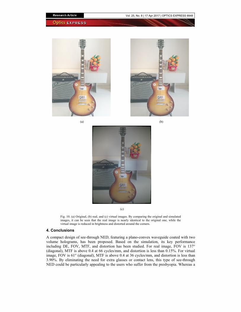
Fig. 10. (a) Original, (b) real, and (c) virtual images. By comparing the original and simulated images, it can be seen that the real image is nearly identical to the original one, while the virtual image is reduced in brightness and distorted around the corners.
4. Conclusions A compact design of see-through NED, featuring a plano-convex waveguide coated with two volume holograms, has been proposed. Based on the simulation, its key performance including DE, FOV, MTF, and distortion has been studied. For real image, FOV is 137° (diagonal), MTF is above 0.4 at 66 cycles/mm, and distortion is less than 0.15%. For virtual image, FOV is 61° (diagonal), MTF is above 0.4 at 36 cycles/mm, and distortion is less than 3.90%. By eliminating the need for extra glasses or contact lens, this type of see-through NED could be particularly appealing to the users who suffer from the presbyopia. Whereas a
Vol. 25, No. 8 | 17 Apr 2017 | OPTICS EXPRESS 8948

monocular structure is exemplified in this paper, binocular solution can be realized as well by adding another waveguide to the left of the current one.
Funding Ministry of Science and Technology of the People’s Republic of China (MOST) (2013CB328804, 2015AA017001); Shanghai Rockers Inc. (15H100000157).
Acknowledgments Special thanks to Dr. Stefan Steiner (LightTrans) for the technical support in using VirtualLab Fusion.
Vol. 25, No. 8 | 17 Apr 2017 | OPTICS EXPRESS 8949