Design Of Reinforced Concrete Structures ii Two-Way...
16
Design Of Reinforced Concrete Structures ii Two-Way Slabs 1 1. Inroduction When the ratio (L/S) is less than 2.0, slab is called two-way slab, as shown in the Figure below. Bending will take place in the two directions in a dish-like form. Accordingly, main reinforcement is required in the two directions.
Transcript of Design Of Reinforced Concrete Structures ii Two-Way...
Design Of Reinforced Concrete Structures ii
Two-Way Slabs
1
1. Inroduction
When the ratio (L/S) is less than 2.0, slab is called two-way slab, as shown in the Figure
below. Bending will take place in the two directions in a dish-like form.
Accordingly, main reinforcement is required in the two directions.
Design Of Reinforced Concrete Structures ii
Two-Way Slabs
2
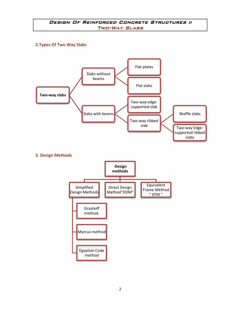
2.Types Of Two Way Slabs
3. Design Methods
Two-way slabs
Slabs without beams
Flat plates
Flat slabs
Slabs with beams
Two-way edge-supported slab
Two-way ribbed slab
Waffle slabs
Two-way Edge-supported ribbed
slabs
Design methods
Simplified Design Methods
Grashoff method.
Marcus method
Egyptian Code method
Direct Design Method"DDM"
Equivalent Frame Method
" EFM "
Design Of Reinforced Concrete Structures ii
Two-Way Slabs
3
4. Direct Design Method "D.D.M"
Before Discussion Of this Method, we have to study some concepts:
1. Limitations:
1. Three or more spans in each direction.
2. Variation in successive spans 33% (
.
3. LL 2 DL
4. Column offset 10% in each direction.
5. L/B 2.
6. For slabs on beams, for one panel
.
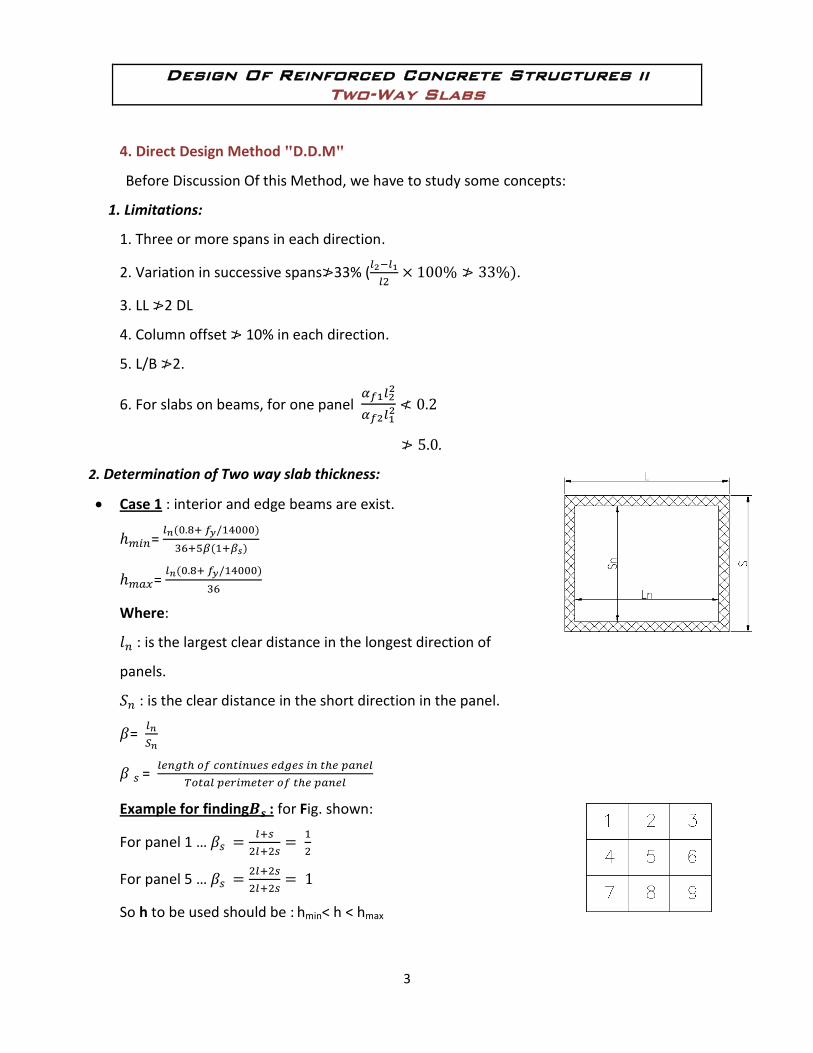
2. Determination of Two way slab thickness:
Case 1 : interior and edge beams are exist.
=
=
Where:
: is the largest clear distance in the longest direction of
panels.
: is the clear distance in the short direction in the panel.
=
=
Example for finding : for Fig. shown:
For panel 1 …
For panel 5 …
So h to be used should be : hmin< h < hmax
Design Of Reinforced Concrete Structures ii
Two-Way Slabs
4
Case 2: interior beams are not existing, thickness can be found according to Table 5,
page 11.
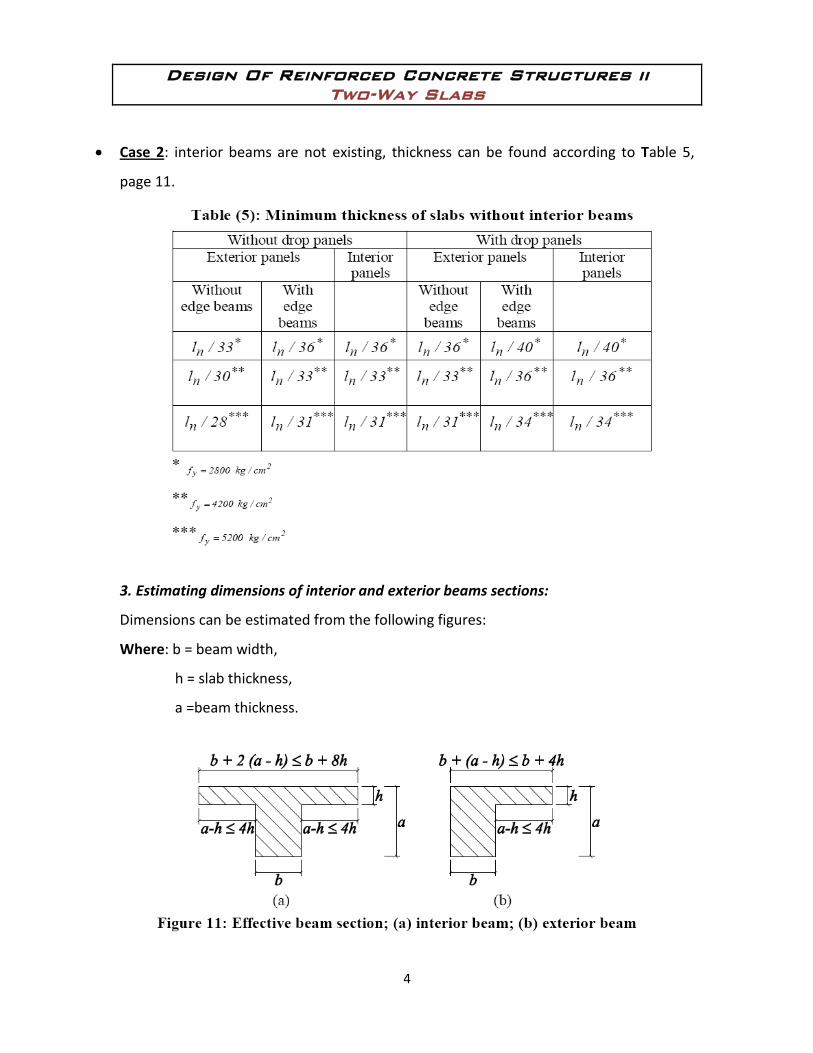
3. Estimating dimensions of interior and exterior beams sections:
Dimensions can be estimated from the following figures:
Where: b = beam width,
h = slab thickness,
a =beam thickness.
Design Of Reinforced Concrete Structures ii
Two-Way Slabs
5
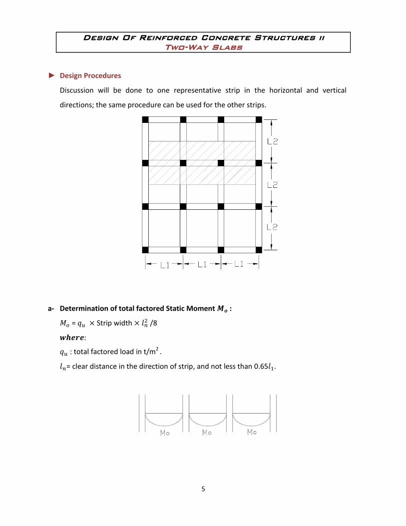
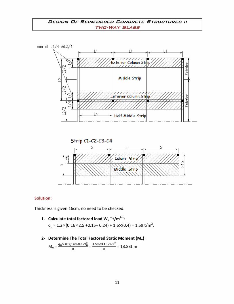
► Design Procedures
Discussion will be done to one representative strip in the horizontal and vertical
directions; the same procedure can be used for the other strips.
a- Determination of total factored Static Moment :
= Strip width /8
: total factored load in t/m2 .
= clear distance in the direction of strip, and not less than 0.65 .

Design Of Reinforced Concrete Structures ii
Two-Way Slabs
6
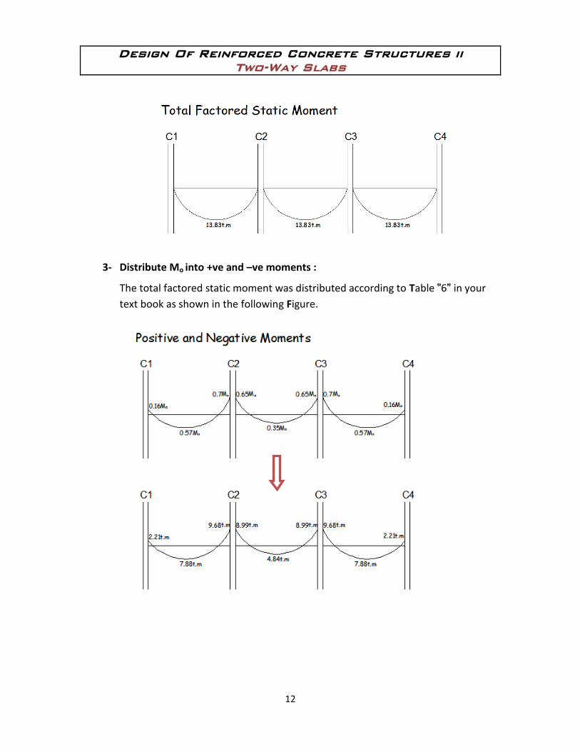
b- Distribution of the total factored static moment to negative and positive moments:
I. For interior Spans:
According to the code, the moments can be distributed according to factores shown in
the Fig.:
II. For Edge Spans :
Static Mom. Mo can be distributed, according to factors given in the Table 6, page 40.
Design Of Reinforced Concrete Structures ii
Two-Way Slabs
7
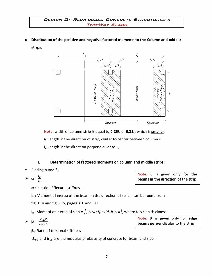
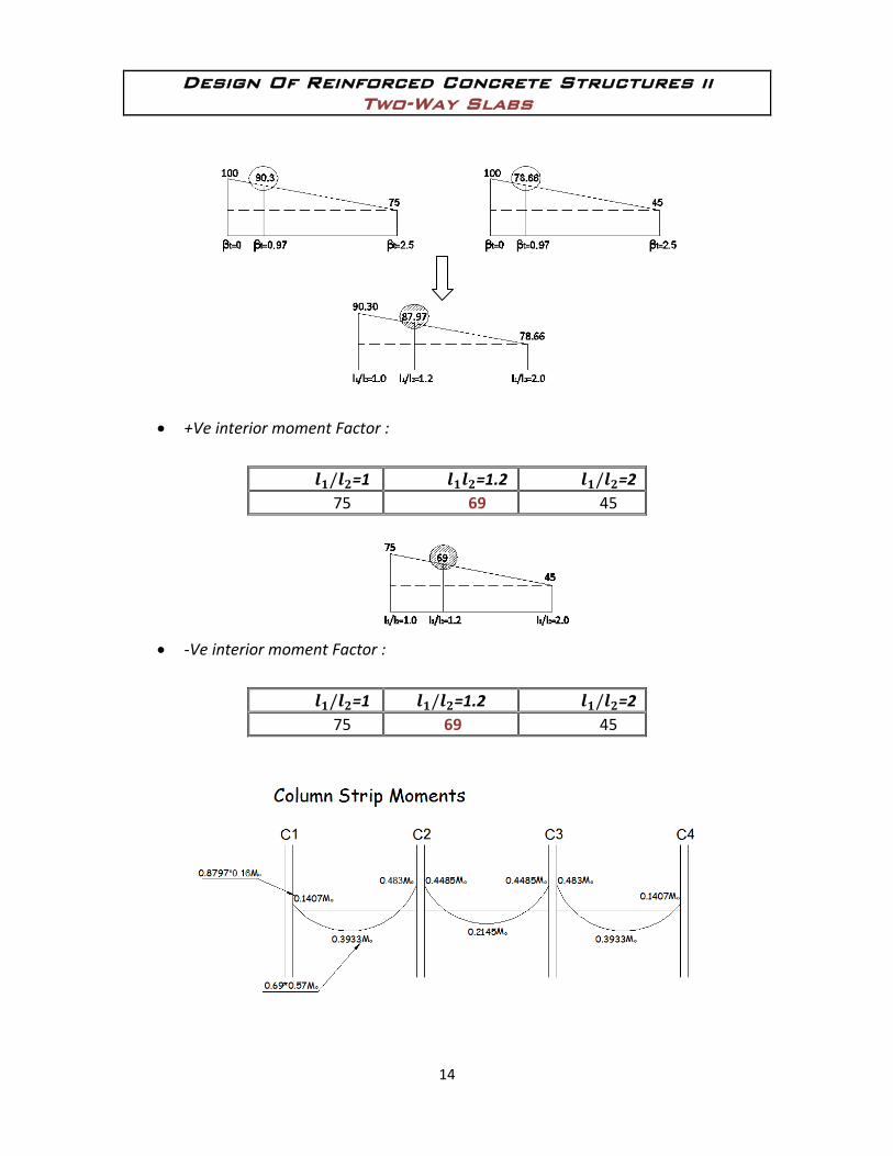
c- Distribution of the positive and negative factored moments to the Column and middle
strips:
Note: width of column strip is equal to 0.25l1 or 0.25l2 which is smaller.
l1: length in the direction of strip, center to center between columns.
l2: length in the direction perpendicular to l1.
I. Determination of factored moments on column and middle strips:
Finding α and βt:
α =
α : is ratio of flexural stiffness .
Ib : Moment of inertia of the beam in the direction of strip… can be found from
fig.8.14 and fig.8.15, pages 310 and 311.
Is : Moment of inertia of slab =
, where is slab thickness.
βt =
,
βt: Ratio of torsional stiffness
and are the modulus of elastisity of concrete for beam and slab.
Note: βt is given only for edge beams perpendicular to the strip
Note: α is given only for the beams in the direction of the strip
Design Of Reinforced Concrete Structures ii
Two-Way Slabs
8
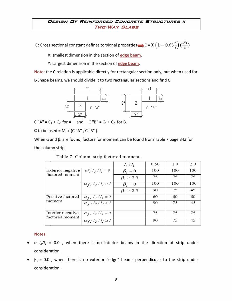
C: Cross sectional constant defines torsional properties C =
X: smallest dimension in the section of edge beam.
Y: Largest dimension in the section of edge beam.
Note: the C relation is applicable directly for rectangular section only, but when used for
L-Shape beams, we should divide it to two rectangular sections and find C.
C "A" = C1 + C2 for A and C "B" = C1 + C2 for B.
C to be used = Max (C "A" , C "B" ).
When α and βt are found, factors for moment can be found from Table 7 page 343 for
the column strip.
Notes:
α l2/l1 = 0.0 , when there is no interior beams in the direction of strip under
consideration.
βt = 0.0 , when there is no exterior “edge” beams perpendicular to the strip under
consideration.
Design Of Reinforced Concrete Structures ii
Two-Way Slabs
9
After finding the moments on the column strip, Moments on the middle strip is the
remain.
II. For the moment on the beam “ if exist ” :
If: α l2/l1 ≥ 1 … The beam moment is 85% of the moment of the column strip.
α l2/l1 = 0 … there is no beam .. mom. = 0
0 < α l2/l1 < 1 … Interpolation have to be done between 0 and 85% to find percentage
of moment on the beam from that of the column strip.
** The Mom. on the remain part of column strip = Tot. Mom. on the column strip –
Mom. on the beam.
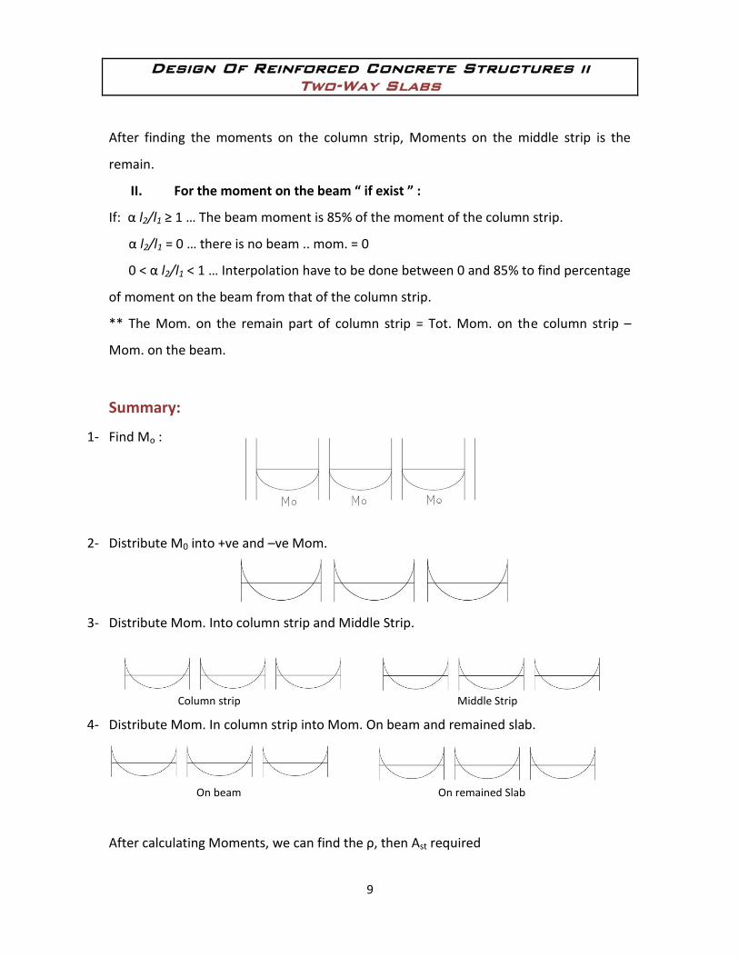
Summary:
1- Find Mo :
2- Distribute M0 into +ve and –ve Mom.
3- Distribute Mom. Into column strip and Middle Strip.
Column strip Middle Strip
4- Distribute Mom. In column strip into Mom. On beam and remained slab.
On beam On remained Slab
After calculating Moments, we can find the ρ, then Ast required
Design Of Reinforced Concrete Structures ii
Two-Way Slabs
10
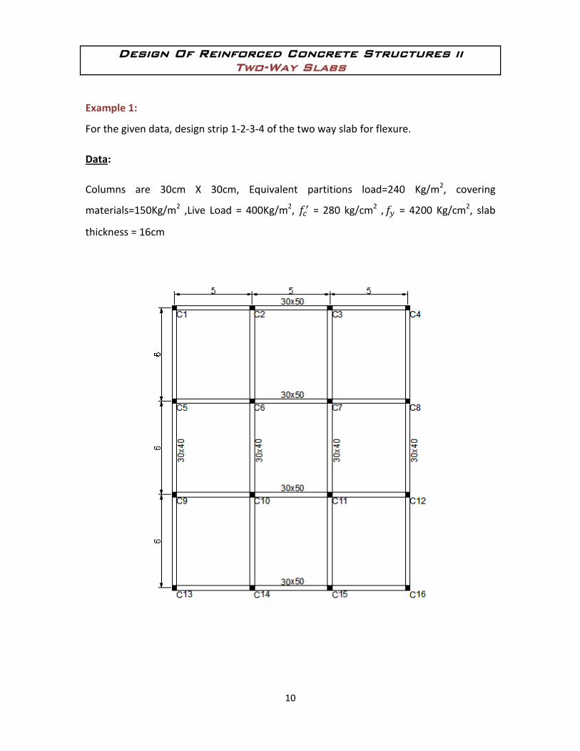
Example 1:
For the given data, design strip 1-2-3-4 of the two way slab for flexure.
Data:
Columns are 30cm X 30cm, Equivalent partitions load=240 Kg/m2, covering
materials=150Kg/m2 ,Live Load = 400Kg/m2, = 280 kg/cm2 = 4200 Kg/cm2, slab
thickness = 16cm
Design Of Reinforced Concrete Structures ii
Two-Way Slabs
11
Solution:
Thickness is given 16cm, no need to be checked.
1- Calculate total factored load Wu "t/m2":
qu = 1.2 (0.16 2.5 +0.15+ 0.24) + 1.6 (0.4) = 1.59 t/m2.
2- Determine The Total Factored Static Moment (Mo) :
Mo =
=
= 13.83t.m
Design Of Reinforced Concrete Structures ii
Two-Way Slabs
12
3- Distribute Mo into +ve and –ve moments :
The total factored static moment was distributed according to Table "6" in your
text book as shown in the following Figure.
Design Of Reinforced Concrete Structures ii
Two-Way Slabs
13
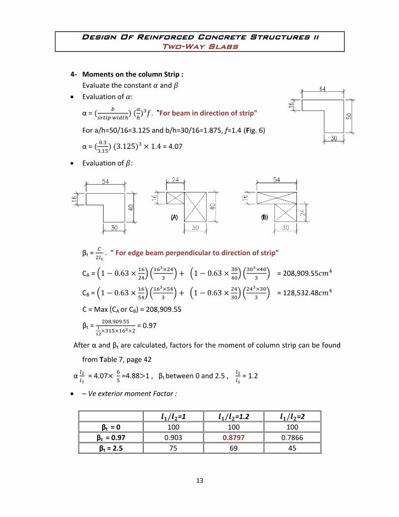
4- Moments on the column Strip :
Evaluate the constant and
Evaluation of :
α =
. "For beam in direction of strip"
For a/h=50/16=3.125 and b/h=30/16=1.875, f=1.4 (Fig. 6)
α =
= 4.07
Evaluation of :
βt =
. " For edge beam perpendicular to direction of strip"
CA =
= 208,909.55
CB =
= 128,532.48
C = Max (CA or CB) = 208,909.55
βt =
= 0.97
After α and βt are calculated, factors for the moment of column strip can be found
from Table 7, page 42
α
= 4.07
=4.88 1 , βt between 0 and 2.5 ,
= 1.2
– Ve exterior moment Factor :
=1 =1.2 =2
βt = 0 100 100 100
βt = 0.97 0.903 0.8797 0.7866
βt = 2.5 75 69 45
Design Of Reinforced Concrete Structures ii
Two-Way Slabs
14
+Ve interior moment Factor :
=1 =1.2 =2
75 69 45
-Ve interior moment Factor :
=1 =1.2 =2
75 69 45
Design Of Reinforced Concrete Structures ii
Two-Way Slabs
15
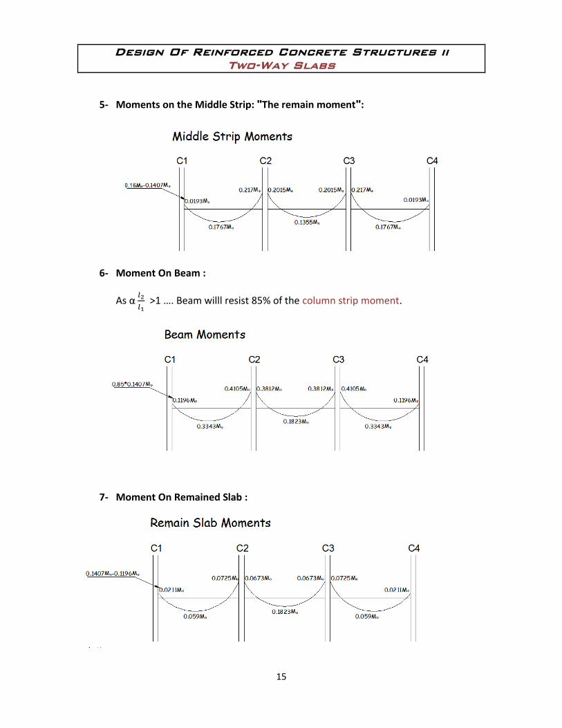
5- Moments on the Middle Strip: "The remain moment":
6- Moment On Beam :
As α
>1 …. Beam willl resist 85% of the column strip moment.
7- Moment On Remained Slab :
Design Of Reinforced Concrete Structures ii
Two-Way Slabs
16
Wish you all the best
Engr. Nour Al Hindi
.
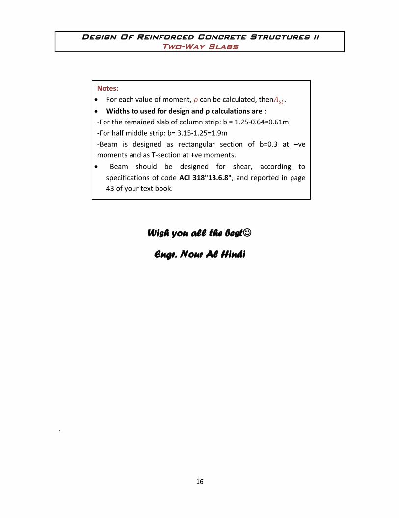
Notes:
For each value of moment, can be calculated, then .
Widths to used for design and ρ calculations are :
-For the remained slab of column strip: b = 1.25-0.64=0.61m
-For half middle strip: b= 3.15-1.25=1.9m
-Beam is designed as rectangular section of b=0.3 at –ve
moments and as T-section at +ve moments.
Beam should be designed for shear, according to
specifications of code ACI 318"13.6.8", and reported in page
43 of your text book.