Design of Reinforced Concrete Civil Structures to Mitigate ... · PDF fileDesign of Reinforced...
43
Design of Reinforced Concrete Civil Structures to Mitigate Against Stray Current Corrosion within a Rail Corridor Colin Morrow, Senior Bridge Engineer Small Bridges Conference Surfers Paradise 28/11/2017
Transcript of Design of Reinforced Concrete Civil Structures to Mitigate ... · PDF fileDesign of Reinforced...
Design of Reinforced Concrete Civil
Structures to Mitigate Against Stray Current
Corrosion within a Rail Corridor
Colin Morrow, Senior Bridge Engineer
Small Bridges Conference
Surfers Paradise
28/11/2017
Introduction
• How Do Stray Currents Occur in a Rail Environment?
• How do Stray Currents Lead to Corrosion?
• Which Structures are affected by Electrolysis Corrosion?
• Guidance & Design Standards
• Electrolysis Corrosion Mitigation Measures
• Testing
• Conclusions and Recommendations
How Do Stray Currents Occur
in a Rail Environment?
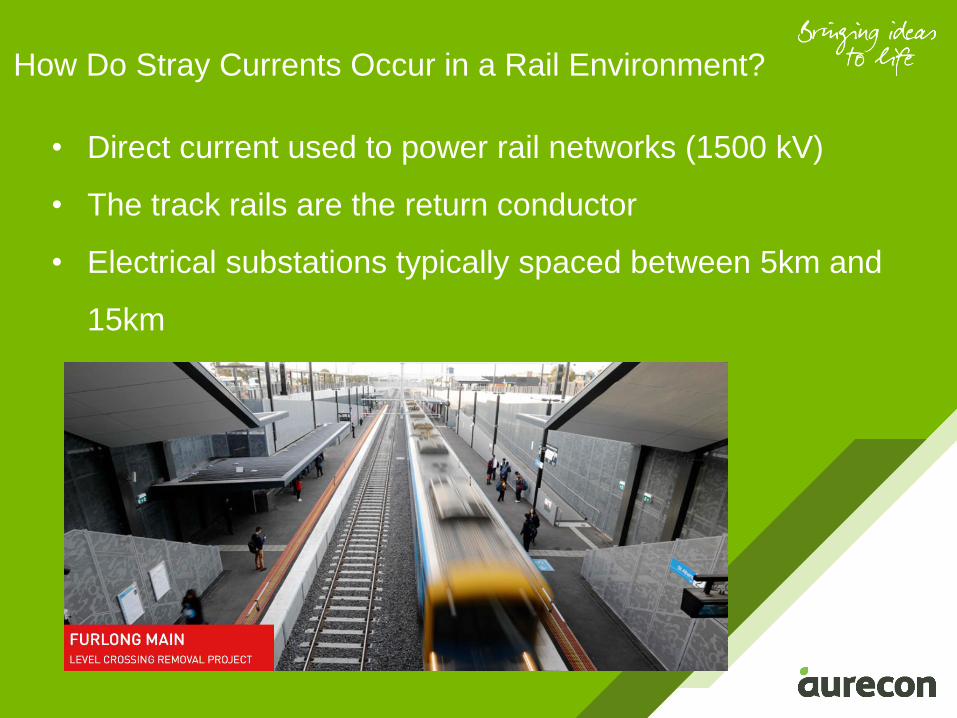
• Direct current used to power rail networks (1500 kV)
• The track rails are the return conductor
• Electrical substations typically spaced between 5km and
15km
How Do Stray Currents Occur in a Rail Environment?

How Do Stray Currents Occur in a Rail Environment?
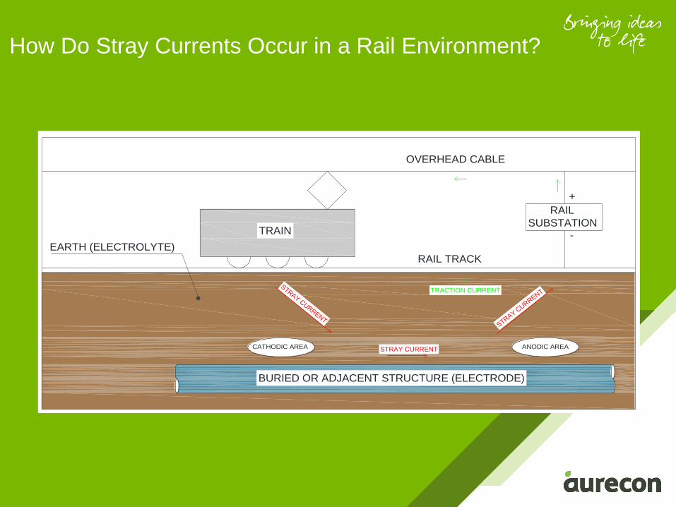
RAIL TRACK
OVERHEAD CABLE
RAIL
SUBSTATION
+
-
TRACTION CURRENT
BURIED OR ADJACENT STRUCTURE (ELECTRODE)
EARTH (ELECTROLYTE)
STRAY CURRENT
CATHODIC AREA
STRAY CURRENT
ANODIC AREA
TRAIN
STRAY CURRENT
How Do Stray Currents Occur in a Rail Environment?
• IDEALLY: Current flows directly to the substation back
though the rails
• REALITY: Not all current travels directly to substation
• Portion of current travels along alternative path through
earth and conductive structural elements
= STRAY CURRENT
• Difficult to analyse magnitude of stray current and flow
paths
How Do Stray Currents Occur in a Rail Environment?
RAIL TRACK
OVERHEAD CABLE
RAIL
SUBSTATION
+
-
TRACTION CURRENT
BURIED OR ADJACENT STRUCTURE (ELECTRODE)
EARTH (ELECTROLYTE)
STRAY CURRENT
CATHODIC AREA
STRAY CURRENT
ANODIC AREA
TRAIN
STRAY CURRENT
How Do Stray Currents
Lead to Corrosion?
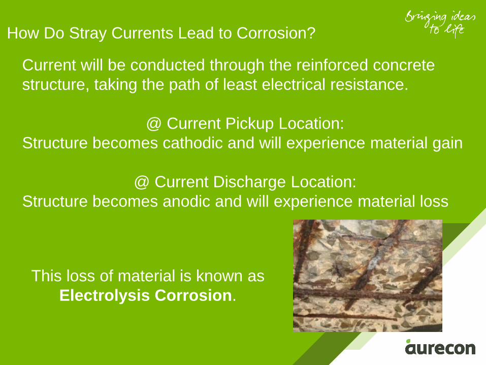
Current will be conducted through the reinforced concrete
structure, taking the path of least electrical resistance.
@ Current Pickup Location:
Structure becomes cathodic and will experience material gain
@ Current Discharge Location:
Structure becomes anodic and will experience material loss
How Do Stray Currents Lead to Corrosion?
This loss of material is known as
Electrolysis Corrosion.
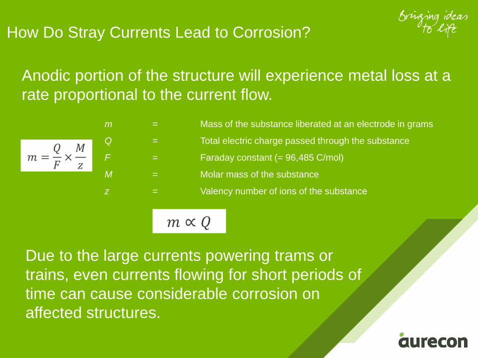
Anodic portion of the structure will experience metal loss at a
rate proportional to the current flow.
How Do Stray Currents Lead to Corrosion?
𝑚 =𝑄
𝐹×𝑀
𝑧
𝑚 ∝ 𝑄
Due to the large currents powering trams or
trains, even currents flowing for short periods of
time can cause considerable corrosion on
affected structures.
m = Mass of the substance liberated at an electrode in grams
Q = Total electric charge passed through the substance
F = Faraday constant (= 96,485 C/mol)
M = Molar mass of the substance
z = Valency number of ions of the substance
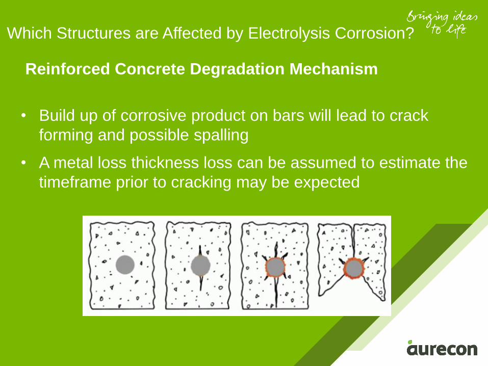
Reinforced Concrete Degradation Mechanism
• Build up of corrosive product on bars will lead to crack
forming and possible spalling
• A metal loss thickness loss can be assumed to estimate the
timeframe prior to cracking may be expected
Which Structures are Affected by Electrolysis Corrosion?
Which structures are affected
by Electrolysis Corrosion?
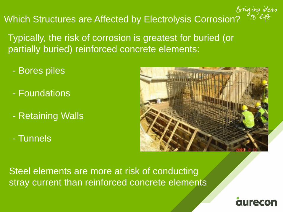
Typically, the risk of corrosion is greatest for buried (or
partially buried) reinforced concrete elements:
Which Structures are Affected by Electrolysis Corrosion?
Steel elements are more at risk of conducting
stray current than reinforced concrete elements
• - Bores piles
• - Foundations
• - Retaining Walls
• - Tunnels
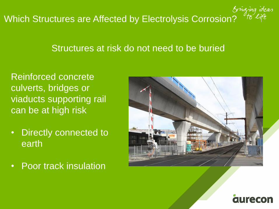
Structures at risk do not need to be buried
Which Structures are Affected by Electrolysis Corrosion?
Reinforced concrete
culverts, bridges or
viaducts supporting rail
can be at high risk
• Directly connected to
earth
• Poor track insulation

Guidance & Design
Standards
Guidance & Design Standards
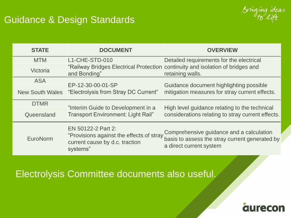
STATE DOCUMENT OVERVIEW
MTM L1-CHE-STD-010
“Railway Bridges Electrical Protection
and Bonding”
Detailed requirements for the electrical
continuity and isolation of bridges and
retaining walls.Victoria
ASAEP-12-30-00-01-SP
“Electrolysis from Stray DC Current”
Guidance document highlighting possible
mitigation measures for stray current effects.New South Wales
DTMR“Interim Guide to Development in a
Transport Environment: Light Rail”
High level guidance relating to the technical
considerations relating to stray current effects.Queensland
EuroNorm
EN 50122-2 Part 2:
“Provisions against the effects of stray
current cause by d.c. traction
systems”
Comprehensive guidance and a calculation
basis to assess the stray current generated by
a direct current system
Electrolysis Committee documents also useful.
Electrolysis Corrosion
Mitigation Measures
1. Provision of Electrical Segregation
2. Provision of Electrical Continuity
3. Isolation of Structural Elements from Stray Current
4. Isolation of Rail Tracks from Earth
5. Use of Drainage Bonds
Electrolysis Corrosion Mitigation Measures
Provision of Electrical Segregation
- risk of electrolysis corrosion occurring
increases with the extent of the
electrically continuous section of a
structure
- Reducing the size or length of a
continuous element or segregating the
element into smaller elements will
reduce the risk or impact of stray current
corrosion.
Electrolysis Corrosion Mitigation Measures
Provision of Electrical Continuity
The reinforcement within a
reinforced concrete element subject
to stray currents should be made
continuous, in order to:
Provision of Electrical Continuity
• provide larger steel mass
from which the current will
leave the structure
• minimise effects of bar to
bar corrosion
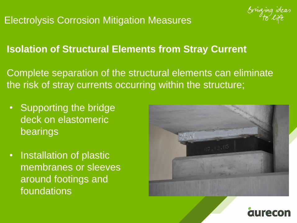
Isolation of Structural Elements from Stray Current
Complete separation of the structural elements can eliminate
the risk of stray currents occurring within the structure;
Electrolysis Corrosion Mitigation Measures
• Supporting the bridge
deck on elastomeric
bearings
• Installation of plastic
membranes or sleeves
around footings and
foundations
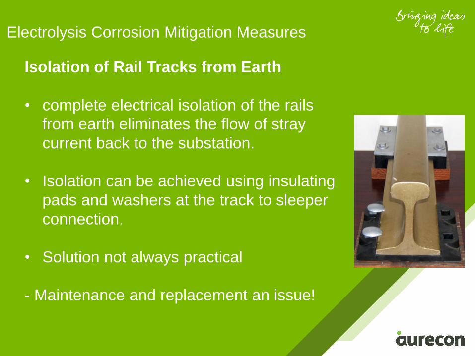
Isolation of Rail Tracks from Earth
• complete electrical isolation of the rails
from earth eliminates the flow of stray
current back to the substation.
• Isolation can be achieved using insulating
pads and washers at the track to sleeper
connection.
• Solution not always practical
- Maintenance and replacement an issue!
Electrolysis Corrosion Mitigation Measures
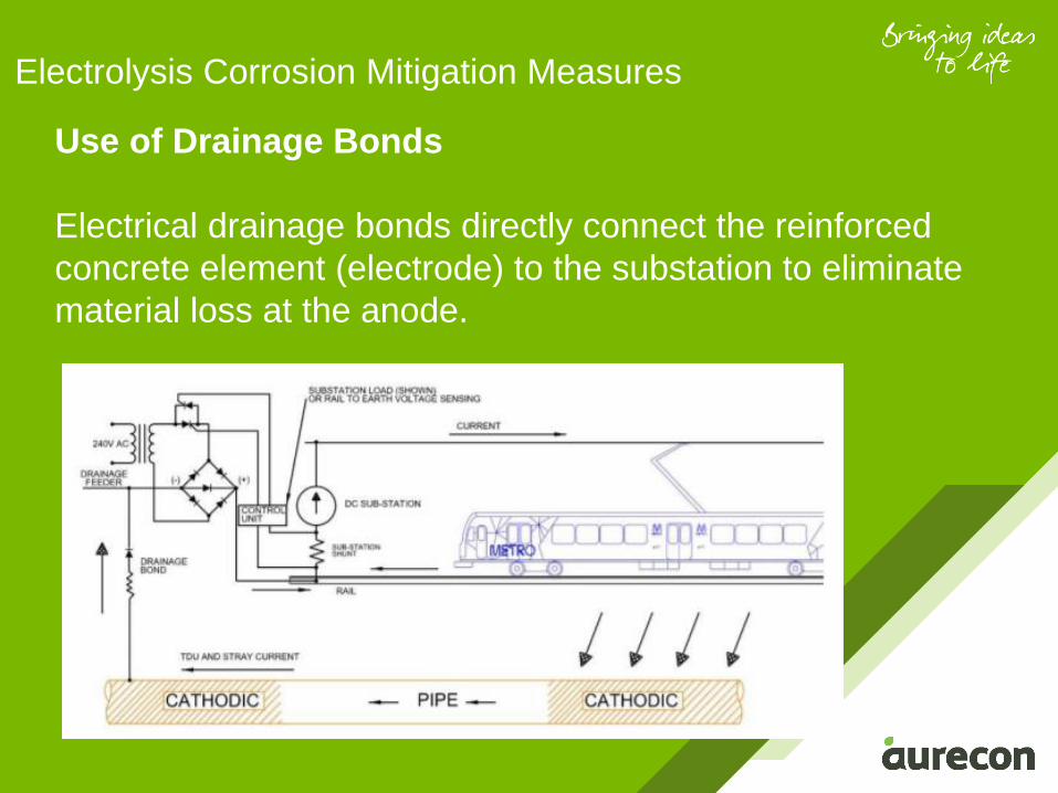
Use of Drainage Bonds
Electrical drainage bonds directly connect the reinforced
concrete element (electrode) to the substation to eliminate
material loss at the anode.
Electrolysis Corrosion Mitigation Measures
Provision of Electrical
Segregation
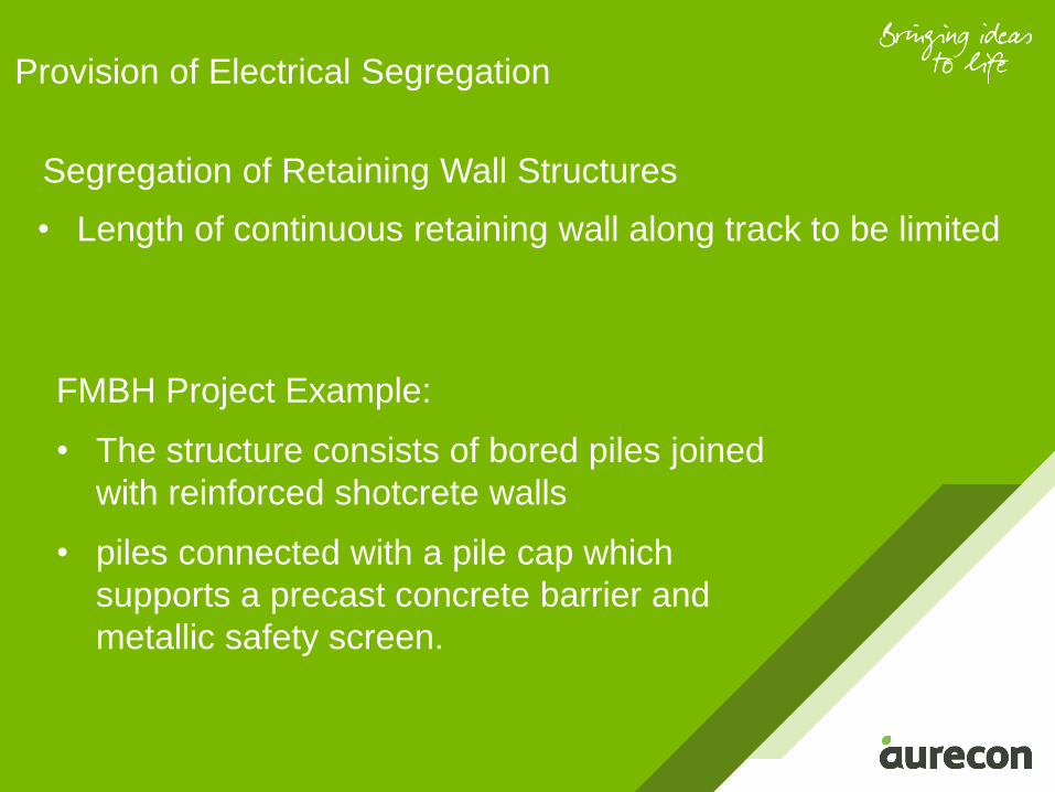
Segregation of Retaining Wall Structures
Provision of Electrical Segregation
FMBH Project Example:
• The structure consists of bored piles joined
with reinforced shotcrete walls
• piles connected with a pile cap which
supports a precast concrete barrier and
metallic safety screen.
• Length of continuous retaining wall along track to be limited
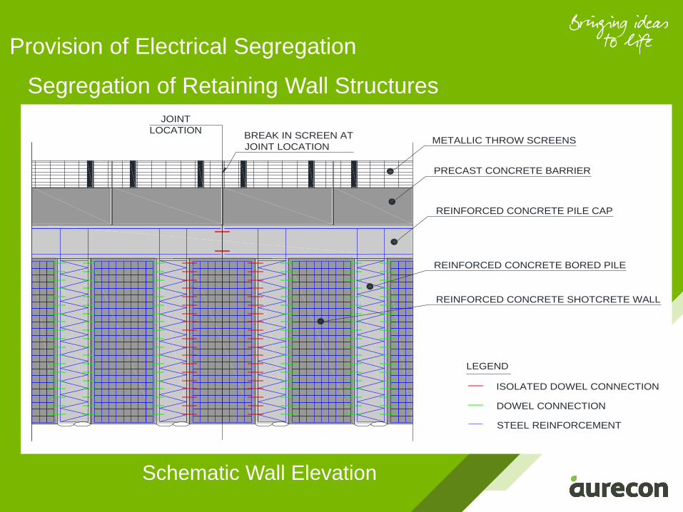
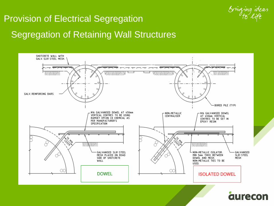
Provision of Electrical Segregation
Segregation of Retaining Wall Structures
JOINT
LOCATION
REINFORCED CONCRETE PILE CAP
PRECAST CONCRETE BARRIER
METALLIC THROW SCREENSBREAK IN SCREEN AT
JOINT LOCATION
REINFORCED CONCRETE BORED PILE
REINFORCED CONCRETE SHOTCRETE WALL
LEGEND
ISOLATED DOWEL CONNECTION
DOWEL CONNECTION
STEEL REINFORCEMENT
Schematic Wall Elevation
Provision of Electrical Segregation
Segregation of Retaining Wall Structures
Provision of Electrical Segregation
FMBH Project
• Main Road bridge structure with span of 20m and width of
75m
• Superstructure consisted of prestressed beams and was
integral at the abutment
• structure electrically split at deck step location with no
continuity of concrete or steel
Segregation of Bridge Structures
• Continuous bridge lengths along rail tracks to be limited
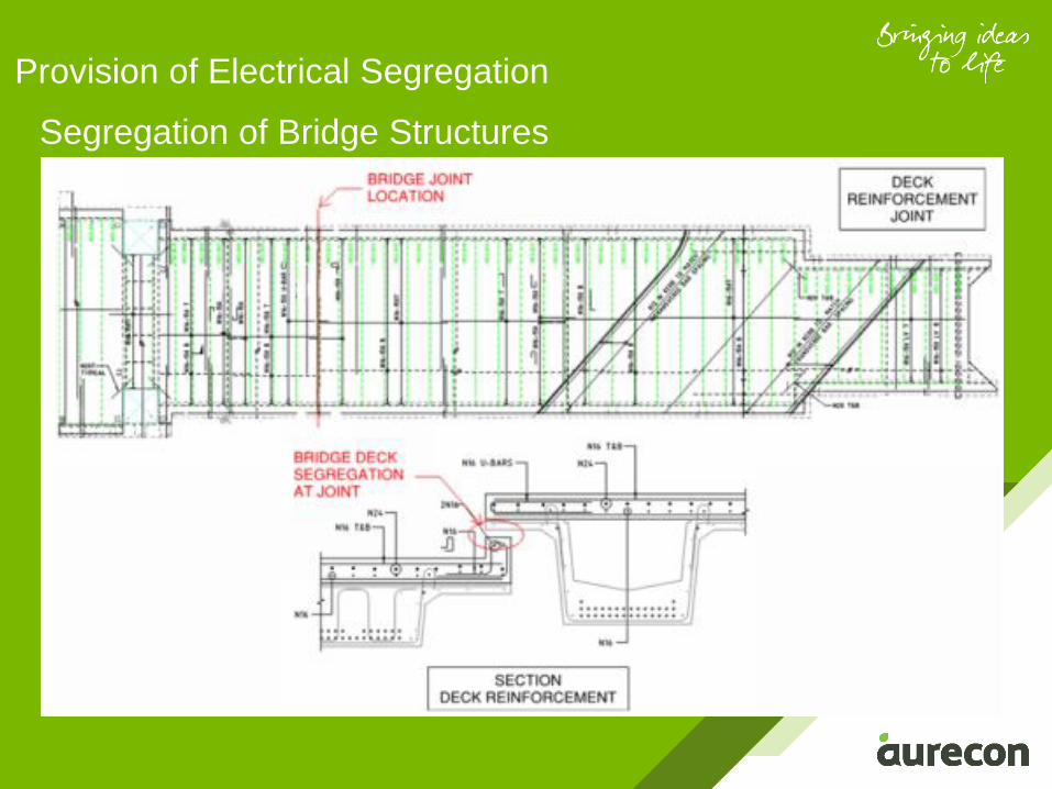
Segregation of Bridge Structures
Provision of Electrical Segregation
Provision of Electrical Segregation
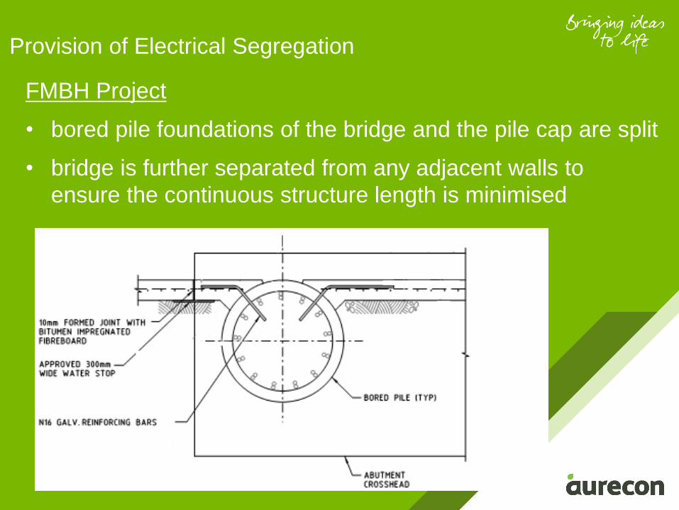
FMBH Project
• bored pile foundations of the bridge and the pile cap are split
• bridge is further separated from any adjacent walls to
ensure the continuous structure length is minimised
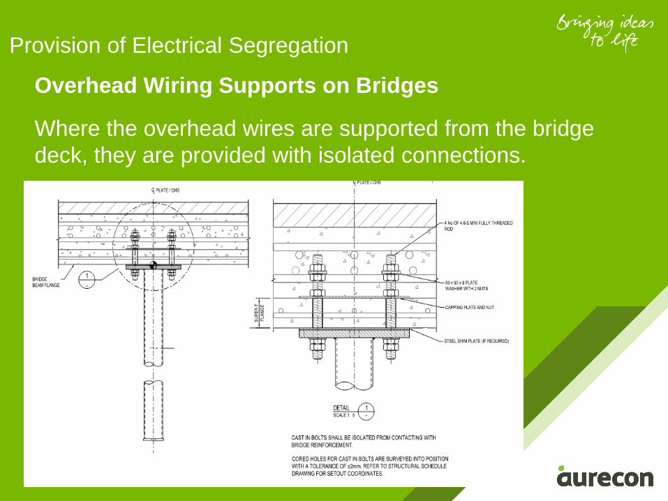
Overhead Wiring Supports on Bridges
Where the overhead wires are supported from the bridge
deck, they are provided with isolated connections.
Provision of Electrical Segregation
Provision of
Electrical Continuity
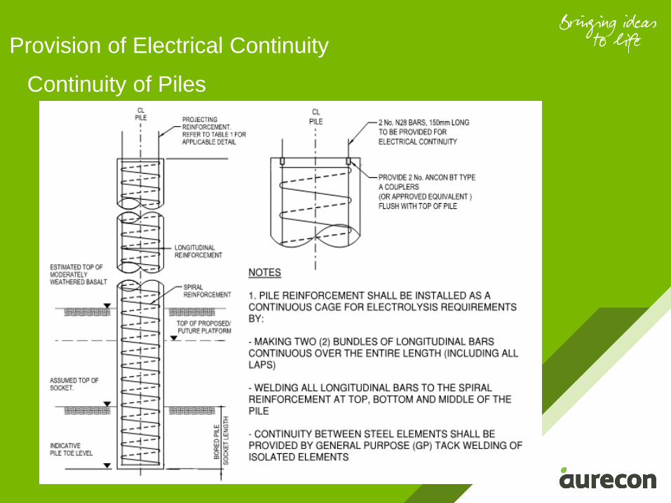
Provision of Electrical Continuity
Continuity of Piles
Provision of Electrical Continuity
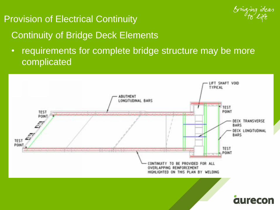
Continuity of Bridge Deck Elements
• requirements for complete bridge structure may be more
complicated
Provision of Electrical Continuity
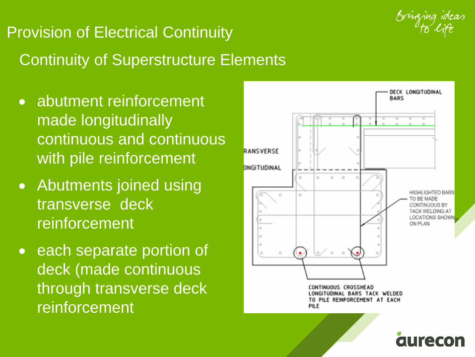
Continuity of Superstructure Elements
• abutment reinforcement
made longitudinally
continuous and continuous
with pile reinforcement
• Abutments joined using
transverse deck
reinforcement
• each separate portion of
deck (made continuous
through transverse deck
reinforcement
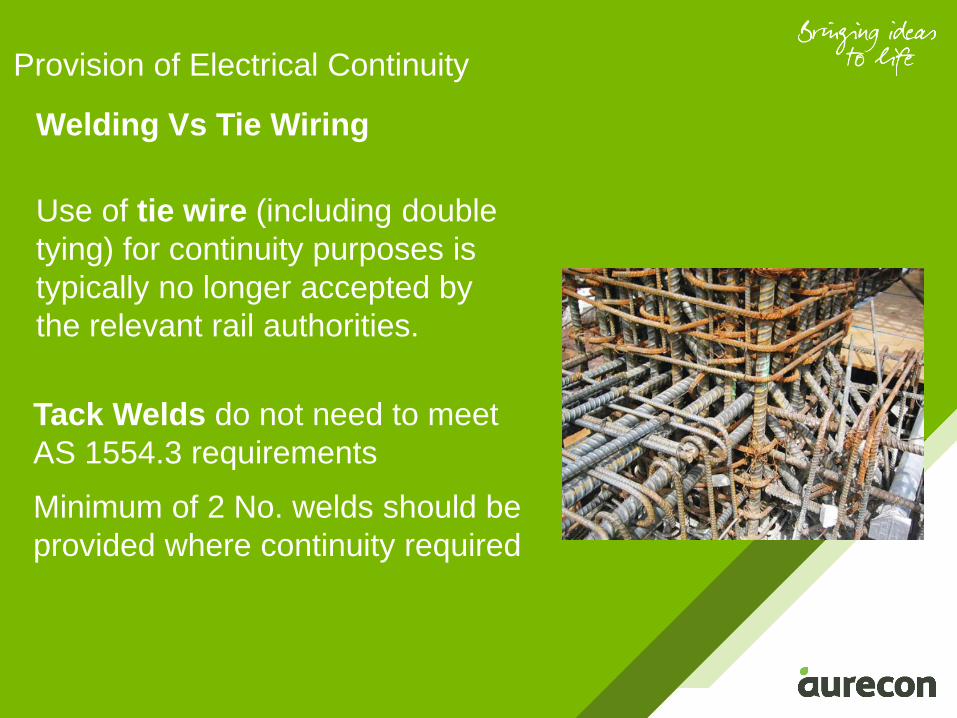
Welding Vs Tie Wiring
Provision of Electrical Continuity
Use of tie wire (including double
tying) for continuity purposes is
typically no longer accepted by
the relevant rail authorities.
Tack Welds do not need to meet
AS 1554.3 requirements
Minimum of 2 No. welds should be
provided where continuity required

Testing
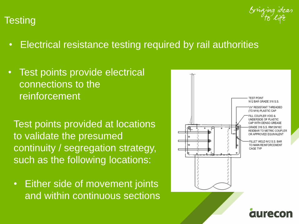
Testing
• Electrical resistance testing required by rail authorities
Test points provided at locations
to validate the presumed
continuity / segregation strategy,
such as the following locations:
• Either side of movement joints
and within continuous sections
• Test points provide electrical
connections to the
reinforcement
Testing
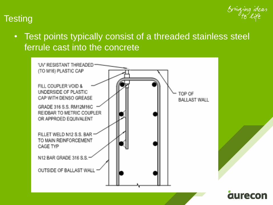
• Test points typically consist of a threaded stainless steel
ferrule cast into the concrete
Conclusion and
Recommendations
• The consideration of stray currents vital to ensuring that
the structure can achieve its design life with minimal
maintenance requirements.
• several potential mitigation measures available to
designers and asset owners
• The chosen measures must be agreed by all parties as
early as possible
Conclusion
• Seek professional advice from material technology experts
in the field
• Stray current strategy must be aligned with the earthing
and bonding strategy
• The mitigation measures must be clearly documented to
facilitate the review and approval of the measures and to
provide clear instruction to the Construction Team.
• Typical treatment measures and details should be
developed by local authorities and asset owners.
Recommendations

Follow us on
www.twitter.com/Aurecon
Join us on
www.facebook.com/Aurecon
Watch us on
www.youtube.com/user/AureconGroup
Follow us on
www.instagram.com/Aurecon
Follow us on
www.linkedin.com/company/Aurecon
Follow us on
www.slideshare.net/Aurecon
Thank You