Design of reinforced concrete beams with steel fibers in ...
14
© 2018 IBRACON Volume 11, Number 5 (October 2018) p. 997 – 1024 • ISSN 1983-4195 http://dx.doi.org/10.1590/S1983-41952018000500006 Design of reinforced concrete beams with steel fibers in the ultimate limit state Verificação de vigas de concreto armado reforçadas com fibras de aço no estado limite último a Universidade de São Paulo, Escola Politécnica, São Paulo, SP, Brasil; b Universidade Estadual de Campinas, Faculdade de Engenharia Civil, Arquitetura e Urbanismo, Campinas, SP, Brasil Received: 29 Jun 2017 • Accepted: 10 Jul 2018 • Available Online: This is an open-access article distributed under the terms of the Creative Commons Attribution License T. E. T. BUTTIGNOL a [email protected] J. F. FERNANDES a julianaff[email protected] T. N. BITTENCOURT a [email protected] J. L. A. O. SOUSA b [email protected] Abstract Resumo This paper carries out a design analysis of reinforced concrete beams with steel fibers following the fib Model Code 2010 (MC 2010) procedures. The values obtained from the design calculations are compared with the experimental results of reinforced concrete beams with 20kg/m 3 and 60 kg/m 3 of steel fibers submitted to four-point bending tests. In the first part, the procedures for the classification and characterization of the mate- rial are explained. The experimental results of three-point bending tests performed on notched steel fiber reinforced concrete (FRC) beams follow- ing EN 14651 procedures are described. Moreover, the characterization of the FRC beams according to MC 2010, are carried out. In the second part, the flexural design of reinforced concrete beams with steel fibers, according to MC 2010, is carried out. A sectional analysis is performed in order to obtain the moment-curvature and the force-vertical displacement curves. The theoretical values are compared with the experimental results. Besides, a linear statistic analysis by means of the Rule of Mixture is carried out in order to analyze the variation of the flexural capacity of the reinforced beams with different amounts of steel fibers. The results demonstrated that the design rules described in the MC 2010 are on the safe side. The flexural resistance of concretes with different amounts of fiber incorporation can be determined by the Rule of Mixture, which has shown a high correlation factor (R 2 ) with the experimental values. Keywords: fiber reinforced concrete, design procedures, mechanical behavior, constitutive law, rule of mixture. Este artigo faz uma verificação de vigas de concreto armado reforçadas com fibras de aço (CARF) seguindo as recomendações do fib Model Code 2010 (MC 2010). Os modelos de cálculo são comparados com os resultados experimentais de vigas de concreto armado reforçadas com 20 kg/m 3 e 60 kg/m 3 de fibras de aço, submetidas a ensaios de flexão em quatro pontos. Na primeira parte é descrito o procedimento para a classificação e ca- racterização do material. São apresentados os resultados dos ensaios à flexão em três pontos de vigas entalhadas de concreto reforçado com fibras de acordo com as prescrições da EN 14651. Além disso, é realizada a caracterização das vigas de CRF seguindo as recomendações do MC 2010. Na segunda parte é realizada a verificação à flexão das vigas de CARF seguindo os procedimentos de cálculo recomendados pelo MC 2010. É feita uma análise seccional pelo método das lamelas para a obtenção das curvas momento-curvatura e força-deslocamento vertical. Os resultados são comparados com os valores experimentais. Além disso, é realizada uma análise estatística linear a partir da Regra da Mistura (Rule of Mixture) para verificar a variação da resistência à flexão das vigas em função da quantidade de fibras incorporadas no concreto. Os resultados demonstraram que os procedimentos de cálculo descritos no MC 2010 estão a favor da segurança. A determinação da resistência à flexão de concretos com diferentes teores de fibras pode ser obtida a partir da Regra da Mistura, que mostrou um alto grau de correlação R 2 em relação aos valores experimentais. Palavras-chave: concreto reforçado com fibras; análise estrutural, comportamento mecânico, leis constitutivas, regra da mistura.
Transcript of Design of reinforced concrete beams with steel fibers in ...

© 2018 IBRACON
Volume 11, Number 5 (October 2018) p. 997 – 1024 • ISSN 1983-4195http://dx.doi.org/10.1590/S1983-41952018000500006
Design of reinforced concrete beams with steel fibers in the ultimate limit state
Verificação de vigas de concreto armado reforçadas com fibras de aço no estado limite último
a Universidade de São Paulo, Escola Politécnica, São Paulo, SP, Brasil;b Universidade Estadual de Campinas, Faculdade de Engenharia Civil, Arquitetura e Urbanismo, Campinas, SP, Brasil
Received: 29 Jun 2017 • Accepted: 10 Jul 2018 • Available Online:
This is an open-access article distributed under the terms of the Creative Commons Attribution License
T. E. T. BUTTIGNOL a
J. F. FERNANDES a
T. N. BITTENCOURT a
J. L. A. O. SOUSA b
Abstract
Resumo
This paper carries out a design analysis of reinforced concrete beams with steel fibers following the fib Model Code 2010 (MC 2010) procedures. The values obtained from the design calculations are compared with the experimental results of reinforced concrete beams with 20kg/m3 and 60 kg/m3 of steel fibers submitted to four-point bending tests. In the first part, the procedures for the classification and characterization of the mate-rial are explained. The experimental results of three-point bending tests performed on notched steel fiber reinforced concrete (FRC) beams follow-ing EN 14651 procedures are described. Moreover, the characterization of the FRC beams according to MC 2010, are carried out. In the second part, the flexural design of reinforced concrete beams with steel fibers, according to MC 2010, is carried out. A sectional analysis is performed in order to obtain the moment-curvature and the force-vertical displacement curves. The theoretical values are compared with the experimental results. Besides, a linear statistic analysis by means of the Rule of Mixture is carried out in order to analyze the variation of the flexural capacity of the reinforced beams with different amounts of steel fibers. The results demonstrated that the design rules described in the MC 2010 are on the safe side. The flexural resistance of concretes with different amounts of fiber incorporation can be determined by the Rule of Mixture, which has shown a high correlation factor (R2) with the experimental values.
Keywords: fiber reinforced concrete, design procedures, mechanical behavior, constitutive law, rule of mixture.
Este artigo faz uma verificação de vigas de concreto armado reforçadas com fibras de aço (CARF) seguindo as recomendações do fib Model Code 2010 (MC 2010). Os modelos de cálculo são comparados com os resultados experimentais de vigas de concreto armado reforçadas com 20 kg/m3 e 60 kg/m3 de fibras de aço, submetidas a ensaios de flexão em quatro pontos. Na primeira parte é descrito o procedimento para a classificação e ca-racterização do material. São apresentados os resultados dos ensaios à flexão em três pontos de vigas entalhadas de concreto reforçado com fibras de acordo com as prescrições da EN 14651. Além disso, é realizada a caracterização das vigas de CRF seguindo as recomendações do MC 2010. Na segunda parte é realizada a verificação à flexão das vigas de CARF seguindo os procedimentos de cálculo recomendados pelo MC 2010. É feita uma análise seccional pelo método das lamelas para a obtenção das curvas momento-curvatura e força-deslocamento vertical. Os resultados são comparados com os valores experimentais. Além disso, é realizada uma análise estatística linear a partir da Regra da Mistura (Rule of Mixture) para verificar a variação da resistência à flexão das vigas em função da quantidade de fibras incorporadas no concreto. Os resultados demonstraram que os procedimentos de cálculo descritos no MC 2010 estão a favor da segurança. A determinação da resistência à flexão de concretos com diferentes teores de fibras pode ser obtida a partir da Regra da Mistura, que mostrou um alto grau de correlação R2 em relação aos valores experimentais.
Palavras-chave: concreto reforçado com fibras; análise estrutural, comportamento mecânico, leis constitutivas, regra da mistura.

998 IBRACON Structures and Materials Journal • 2018 • vol. 11 • nº 5
Design of reinforced concrete beams with steel fibers in the ultimate limit state
1. Introduction
In the last decades, important developments in the research of fiber reinforced cementitious materials occurred. The fibers ran-domly distributed in the bulk concrete allowed an improvement of the material behaviour at the post-cracking regime, contributing to the reduction and control of crack formation and propagation. Also, an increase in the ductility is observed due to fiber bridging effect and the progressive bond loss and slippage of the fibers (pull out effect), which is responsible for maintaining the cohesion of the concrete cracked sections.The type of fiber (metallic, synthetic, micro or microfiber, straight or hooked-end), volume and distribution are the main factors affecting the material response, characterized by a softening (progressive residual strength loss with crack localization and progressive col-lapse) or hardening behaviour (multicracking stage with strength increase followed by crack localization and failure).The crack opening control guarantees an improvement in the structural durability and concrete strength, reducing concrete per-meability and the ingress of aggressive agents (ions of chloride and sulphates), responsible for steel bars corrosion and concrete degradation. Due to the increase in ductility, fiber reinforced con-crete (FRC) has a higher energy absorption capacity (toughness) compared to conventional concrete, improving the structural per-formance due to static (tensile, torsion, shear) and dynamic (seis-mic, vibrations, cyclic) loads. The incorporation of fibers contributes to the heterogeneity of the material (scattering of the results and standard deviation). Tensile and bending tests (LOGFREN et al [1]; LARANJEIRA et al [2]; SOETENS et al [3]; TEIXEIRA BUTTIGNOL et al [4]) revealed high values of the coefficient of variance of FRC materials, which is mainly caused by fibers randomly distribution and alignment n the bulk matrix. There is also a reduction in the workability of the concrete mixture, directly related to the fibers volume. The devel-opment of self-compacting concrete solved part of the problem of FRC workability containing high dosages of fibers (> 2%). More-over, new casting techniques allowed better control of fibers ori-entation, reducing the variability and increasing the experimental tests predictability.FRC has been largely utilized in rigid pavements and tunnels (pri-mary and secondary layers) for crack control due to shrinkage, thermal and permanent deformations, contributing to improve the structural durability. For structural utilization, substituting partially or totally (in specific cases) the longitudinal steel bars (flexural ca-pacity) and stirrups (shear and torsion), FRC has some disadvan-tages, mainly related to the cost of the materials and the lack of de-sign recommendations in developing countries. On the one hand, the development of new fibers (carbon, steel, polymeric, glass) and the increase in the material utilization is contributing to reduce the cost of production and increase its competitiveness. On the other hand, design codes and recommendations were published in the last years, contributing to the safety design. The design models had evolved to an empirical approach to a more rational and physi-cal method based on probabilistic models.A new paradigm was introduced with the new fib Model Code 2010 [5] (MC 2010), which has introduced two chapters about FRC de-sign aspects, including recommendations for material classification,
characterization, and simplified constitutive models, together with design rules for flexural, shear and torsion. MC 2010 has been the basis for the development of FRC design specifications in national codes. For example, in Brazil, design recommendations for FRC structural applications, based on MC 2010 principles, was produced by IBRACON / ABECE Technical Committee - CT-303 [6].
2. Research significance
The increasing utilization of FRC for structural purposes is related to the attainment of better structural performance, higher durability, and simplification of the construction process (reduction of conven-tional reinforcement). Reliable design models with accurate capac-ity to predict the structural behaviour are needed to allow the utili-zation of the material by designers. Due to the material variability as a result of its heterogeneity, a proper analysis of the mechanical properties, including experimental tests for the classification, char-acterization, and definition of the tensile constitutive law, is essen-tial before its implementation in construction.The structural design procedure is based on simplified models that are described in national and international design procedures and numerical models developed in finite elements (FE) or based on cross-sectional analyses. In large structures (bridges, tall build-ings, offshore constructions, etc.), it is also necessary an experi-mental investigation using reduced scale models in the laboratory to verify and certify the reliability of the assumed design rules.The lack of design specifications is a hindrance to the progress of FRC applications for structural purposes. This paper is aimed to contribute to improving the knowledge of FRC design specifications using verification in the Ultimate Limit State (ULS) of reinforced con-crete (RC) beams with steel fibers incorporation tested in bending. This is relevant, specifically in the case of Brazil, due to the recent publication of the IBRACON / ABECE [6] recommendations for the utilization of non-conventional materials for concrete structures. In the first part of the paper, the experimental tests are described. The tests consist of three-point bending (3PB) tests in FRC notched beams according to EN 14651 [7]. The experimental data were used for the classification and characterization of the material following MC 2010 guidelines. The results of four-point bending (4PB) tests on reinforced concrete (RC) beams with steel fibers incorporation are also presented. The tests are part of a large experimental cam-paign developed in the Technological Hall at the Polytechnic School of the University of Sao Paulo in the frame of scientific cooperation with Furnas Hydropower company. In the second part, the verifica-tions in thet ULS of RC beams with steel fibers incorporation are carried out using MC 2010 design rules. A comparison between the experimental results and sectional analysis is performed. The effi-ciency of the rule of mixture to predict the flexural capacity of RC beams with different volumes of fibers is also investigated.
3. Mechanical characterization
The main objective of the characterization of the material is to determine the residual tensile characteristic curve that is directly related to the material response (softening or hardening). Uniaxial tensile tests are not often adopted due to the inherent complexi-ties of the test procedure. For example, a special apparatus is

999IBRACON Structures and Materials Journal • 2018 • vol. 11 • nº 5
T. E. T. BUTTIGNOL | J. F. FERNANDES | T. N. BITTENCOURT | J. L. A. O. SOUSA
necessary to fix the specimen-ends. Moreover, a perfect alignment of the specimen must be guaranteed to avoid eccentricities and additional forces in the form of bending moment. Also, the test re-sult is affected by the boundary conditions (fixed-end or rotating-end), as stated by VAN MIER [8]. The Brazilian test does not give any information about FRC behav-iour at the post-cracking regime. The test is suitable to obtain the ten-sile strength of concrete materials. As a result, FRC characterization is generally performed using indirect tests such as three-point (EN 14651 [7]) and four-point (UNI 11039 [9]) bending tests with notched prismatic specimens. The problem of the flexural tests for tensile char-acterization is the inevitability to perform an inverse analysis to ob-tain the residual tensile response in terms of nominal stress vs. crack opening displacement. Simplified numerical methods were proposed by different authors, for example, QIAN and LI [10]; MOBASHER et al. [11]; SOUSA and GETTU [12]; AMIN et al. [13]. The design routine of SOUSA and GETTU (2006) model was in-corporated in an algorithm based on Java plataform. The program named fitFG includes a user-friendly graphic interface (SANTOS et al. [14]). The algorithm determines the constitutive relation in ten-sion of FRC materials using inverse analysis using experimental results of 3PB tests. The experimental data (input) can be included in terms of force versus displacement (P-∆) or force versus crack-mouth opening (P-CMOD). The software allows the user to choose three different tensile models: Hordjik (exponential) for plain con-crete and bilinear or trilinear models for both plain and fiber rein-forced concrete.The problem of the inverse analysis is that it is necessary complex mathematical formulations with iterative procedures, demanding computational models. The simplified constitutive model described in MC 2010 has the great advantage that it avoids the calculation of complex computational models. In this case, the solution can be obtained directly by the results of the classification of the material, as is described in section 3.2.FRC characterization is important to determine the mechanical properties and to guarantee the reliability of the design procedure. Due to the high heterogeneity of the material, a high spread of the experimental values is found, leading to a higher standard deviation and lower characteristic strength values compared to
conventional concrete. According to LARANJEIRA et al. [2], a coef-ficient of variation (CV) higher than 20% is normally found in FRC bending tests. CARMONA et al. [15] found values of CV, at the post-cracking phase, up to 30% in Barcelona tests. Experimental results of 3PB tests carried out by SOETENS et al. [3] resulted in a variable CV of fR1 (SLS, CMOD=0.5 mm) and fR3 (ULS, CMOD=2.5 mm) within the range of 10% and 33%.Due to FRC heterogeneity, it is recommended that the experimental tests are carried out using specimens prepared (mixture, casting, and curing) as close as possible of the real construction conditions. This will allow more realistic and reliable analysis of the effect of fibers orientation and distribution on the material response.
3.1 Three-point bending tests
FRC characterization was carried out using 3PB tests using notched beams and following EN 14651 [7] procedure, as is shown in Figure 1. The tests were developed in the Technological Hall at the University of Sao Paulo, using a universal hydraulic press Instron 8802 with deformation control and strength capacity of 250 kN. The crack mouth-opening was measured with a clip-gauge.Overall, twelve tests on prismatic beams with 150 mm x 150 mm x 550 mm, reinforced with two different steel fiber volumes (20 kg/m3 and 60 kg/m3), were performed. Concrete mix design is shown in Table 1.
Figure 1Three-point bending test (EN 14651 [7]) with measures in mm
Table 1Concrete mix design
Material Quantity (Kg/m3)Cement 404Gravel
(2.36 – 12.7 mm) 864
Quartz sand 569Artificial sand 410
Water 182Superplasticizer 2.45Hyperplasticizer 4.55
Total mass 2436

1000 IBRACON Structures and Materials Journal • 2018 • vol. 11 • nº 5
Design of reinforced concrete beams with steel fibers in the ultimate limit state
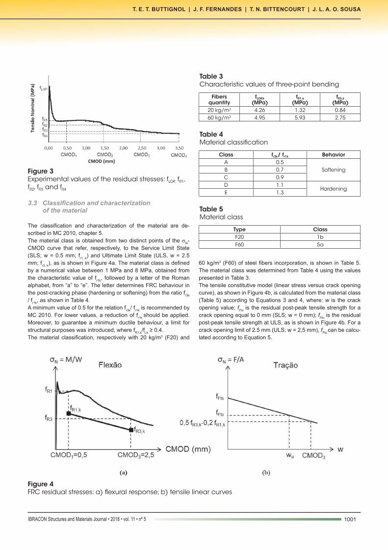
The tests results, in terms of nominal stress (σN = M ⁄ W) versus crack-mouth opening (CMOD), are shown in Figure 2.The values of the residual tensile stresses for different crack open-ings, obtained from the experimental tests (Figure 2), are shown in Table 2. The designation of the stresses fLOP, fR1, fR2, fR3, and fR4 are summarized in Figure 3.From the results, one can notice the high scattering of the values, especially the residual stresses, which shows increasing CV val-ues for higher crack openings. The CV values are in agreement with the ones found by LARANJEIRA et al. [2].
3.2 Characteristic values
The characteristic values (Table 3) were calculated according to EUROCODE 1 [16], from the values presented in Table 2, as de-
scribed in Equation 1, where: Xm is the mean stress; Vx is the coef-ficient of variation.The coefficient of variation is calculated according to Equation 2, where: σx is the standard deviation; Km is a parameter de-pendent on the number of specimens tested and the previously knowledge of Vx. In this case, the coefficient of variation is not previously known, since there is no available information about the material.
(1)
(2)
The characteristic values of the 3PB tests (fLOP,k, fR1,k, fR3,k), obtained from Table 2, are shown in Table 3.
Figure 2Experimental results from three-point bending tests a) specimens with 20 kg/m3 of fibers; b) specimens with 60 kg/m3 of fibers
Table 2Three-point bending test results (MPa) and coefficient of variation (CV)
Cf (kg/m3)
Residual strength
Specime Mean(Xm)
CV (%)1 2 3 4 5 6
20
fLOP 4.63 6.51 6.88 6.98 6.62 5.70 6.22 14.47fR1 2.36 1.63 2.60 1.91 1.97 1.99 2.08 16.67fR2 1.66 1.61 2.16 1.64 1.97 1.76 1.80 12.17fR3 1.14 0.99 1.35 1.27 1.09 1.02 1.14 12.27fR4 0.93 0.77 1.00 0.90 0.89 0.64 0.86 15.07
60
fLOP 5.80 9.45 7.87 7.05 8.81 7.63 7.77 16.61fR1 8.87 15.75 15.76 10.26 15.19 10.78 12.77 24.56fR2 7.91 16.30 12.68 9.79 14.76 9.42 11.81 27.99fR3 7.48 15.30 9.35 8.30 13.75 7.26 10.24 33.53fR4 6.27 13.43 7.30 7.32 12.73 5.74 8.80 38.37
1001IBRACON Structures and Materials Journal • 2018 • vol. 11 • nº 5
T. E. T. BUTTIGNOL | J. F. FERNANDES | T. N. BITTENCOURT | J. L. A. O. SOUSA
3.3 Classification and characterization of the material
The classification and characterization of the material are de-scribed in MC 2010, chapter 5.The material class is obtained from two distinct points of the σN-CMOD curve that refer, respectively, to the Service Limit State (SLS; w = 0.5 mm; fr1, k) and Ultimate Limit State (ULS, w = 2.5 mm; fr3, k), as is shown in Figure 4a. The material class is defined by a numerical value between 1 MPa and 8 MPa, obtained from the characteristic value of fr1k, followed by a letter of the Roman alphabet, from “a” to “e”. The letter determines FRC behaviour in the post-cracking phase (hardening or softening) from the ratio fr3k / fr1k, as shown in Table 4.A minimum value of 0.5 for the relation fr3k/ fr1k is recommended by MC 2010. For lower values, a reduction of fr1k should be applied. Moreover, to guarantee a minimum ductile behaviour, a limit for structural purposes was introduced, where fR1,k/fLk ≥ 0.4.The material classification, respectively with 20 kg/m3 (F20) and
60 kg/m3 (F60) of steel fibers incorporation, is shown in Table 5. The material class was determined from Table 4 using the values presented in Table 3.The tensile constitutive model (linear stress versus crack opening curve), as shown in Figure 4b, is calculated from the material class (Table 5) according to Equations 3 and 4, where: w is the crack opening value; fFts is the residual post-peak tensile strength for a crack opening equal to 0 mm (SLS; w = 0 mm); fFtu is the residual post-peak tensile strength at ULS, as is shown in Figure 4b. For a crack opening limit of 2.5 mm (ULS; w = 2,5 mm), fFtu can be calcu-lated according to Equation 5.
Figure 3Experimental values of the residual stresses: fLOP, fR1, fR2, fR3 and fR4
Table 3Characteristic values of three-point bending
Fibers quantity
fLOP,k
(MPa)fR1,k
(MPa)fR3,k
(MPa)20 kg/m3 4.26 1.32 0.8460 kg/m3 4.95 5.93 2.75
Figure 4FRC residual stresses: a) flexural response; b) tensile linear curves
Table 4Material classification
Class fr3k/ fr1k BehaviorA 0.5
SofteningB 0.7C 0.9D 1.1
HardeningE 1.3
Table 5Material class
Type ClassF20 1bF60 5a

1002 IBRACON Structures and Materials Journal • 2018 • vol. 11 • nº 5
Design of reinforced concrete beams with steel fibers in the ultimate limit state
(3)
(4)
(5)
The residual stresses in bending (fr1,k ; fr3,k) and in tension (fFTS ; fFtu), obtained from the material class, are shown in Table 6.
4. Experimental tests
4.1 Experimental procedure
The RC prismatic beams (unnotched, structural) were subjected to four-point bending tests according to the test setup shown in Figure 5. The beams were reinforced with steel fibers (20 kg/m3 and 60 kg/m3) with a length of 2.2 m and a cross section of 125 mm x 250 mm.The top (negative) longitudinal reinforcement comprises two steel bars of 6.3 mm diameter, and the bottom (positive) re-inforcement consists of two rebars of 16 mm. The transverse reinforcement has stirrups of 8.0 mm diameter spaced every
8 cm in the section between the supports and the points of the application of load. In the central section (between the two points of the application of the load), two stirrups with a spacing of 20 cm were placed. Figure 6 shows the details of the reinforcement.The tests were performed utilizing a servo-hydraulic press from Brasválvula with a load cell capacity of 1000 kN.The displacements were measured using two LVDTs with a stroke of 100 mm from HBM. The test apparatus were fixed in the mid-dle of the span of the beam with metallic supports (“Yokes”), as is shown in Figure 7.
4.2 Experimental results
The experimental results of the RC beams with and without fibers, in terms of force (F) versus vertical displacement (δ), are shown in Figure 8.The comparison of the results demonstrates that fiber incorpora-tion led to an increase in the bearing capacity of approximately 15%. Moreover, a small gain in ductility with an increase in the vertical displacement was noticed.In all cases, there was a ductile failure due to concrete crushing in the compressive zone and steel bars yielding in the tensile zone.
Table 6Residual stresses in bending and tension (in MPa)
Beam F20 F60Class 1b 5a
Bendingfr1,k 1 5fr3,k 0.7 2.5
TensionfFTS 0.45 2.25fFtu 0.15 0.25
Figure 5Experimental test setup (in cm)
Figure 6Reinforcement details of the beams

1003IBRACON Structures and Materials Journal • 2018 • vol. 11 • nº 5
T. E. T. BUTTIGNOL | J. F. FERNANDES | T. N. BITTENCOURT | J. L. A. O. SOUSA
5. Flexural design
The flexural design of the beams in ULS is carried out following MC 2010 procedures. A sectional analysis is performed, and the results are compared with the experimental values. For both analy-ses, the constitutive models (Figure 4) obtained from the material characterization were adopted.
5.1 Design hypotheses
The hypotheses herein assumed for FRC design are the same as those used for reinforced concrete: plane sections remain plane after deformation (Bernoulli’s Law), small displacements, the perfect bond between concrete and steel, idealized constitutive models for con-crete and steel. The most important difference is that in the RC beam
design, concrete tensile stresses are neglected, while in FRC beams, concrete is assumed as a homogeneous material and the contribution of the fibers in the post-cracking phase is considered in the design.In section 7.7.3.1, MC 2010 describes the three main failure modes in the ULS: a) achievement concrete maximum deformation in compression (εcu); b) achievement of steel maximum elongation (εsu); c) achievement of FRC maximum deformation in tension (εFu).Concrete strain variation in the cross section and the stress state at SLS and ELU are shown in Figure 9. From Figure 9b one can observe the tensile zone and the softening / hardening effect due to concrete cracking and the stress transfer to the rebars and fi-bers. In the ULS (Figure 9c), the fibers are responsible for concrete load resistance in tension, where a simplified rectangular diagram is assumed, and the resisting stress is equal to fFtud (fFtud = fFtuk/γf, where γf = 1,5).
Figure 7Experimental test procedure
Figure 8Experimental test results
Figure 9Cross-sectional equilibrium (MC 2010): a) linear variation of the deformation; b) allowed stresses in SLS; c) allowed stresses in ULS

1004 IBRACON Structures and Materials Journal • 2018 • vol. 11 • nº 5
Design of reinforced concrete beams with steel fibers in the ultimate limit state
It is necessary to transform the tensile characteristic curve σN-w in σN-ε for the design calculation. In this case, MC 2010 adopts the concept of characteristic length (BAZANT and CEDOLIN [17]; BARROS et al. [18]; HORDIJK [19]; HILLERBORG et al. [20]) that correlates the crack opening with the deformation (lcs = w ⁄ ε). The characteristic length is equal to the mean crack spacing (srm) in the multicracking phase, ob-tained from experimental tests. In the lack of experimental parameters, the value of lcs can be defined theoretically by the lower value calculated for the mean crack spacing (srm) and the distance between the neutral axis and the extreme fiber subjected to tension (y = h - x), as is shown in Figure 10. For FRC members without reinforcement, when adopting the sectional analysis model assuming the concept of plane section, lcs can be defined as equal to the height of the beam (lcs = h).The neutral axis (x) is determined according to Equation 6 using an elastic analysis of the cracked section, respecting the limits of the crack opening and spacing and neglecting concrete tensile residual strength. For the cracked section, it is assumed that the steel bars are yielding (σs = fy).
(6)
The maximum distance between cracks (ls, max) is defined as the length of the section, from the cracked section, where the bond strength between concrete and steel is developed (the region where occurs the slippage between concrete and the steel bars). MC 2010 describes an equation to determine the ls, max in RC elements rein-
forced with fibers, as is shown in Equation 7, where: k = empirical parameter to consider the effect of concrete cover, taken equal to 1,0; c = concrete cover; τbm = 1.8.fctm = mean bond strength; ρs,ef = As/Ac,ef = steel bar effective ratio; Фs = steel bar diameter; fFtsm = fFtsk / 0.7.
(7)
The mean crack opening is calculated according to Equation 8.
(8)
In the case analysed, the characteristic length (lcs) was assumed as the lower value between the mean crack spacing (srm) and the distance from the neutral axis to the extreme fiber in tension (y). The parameters used to calculate srm are presented in Table 7, while in Table 8 it is shown the values of lcs.The maximum crack opening (wu = lcs
.εFu) was obtained according to MC 2010 from the characteristic value and by setting the ultimate de-formation at 2% (εFu = 2%), respecting the crack limit of w ≤ 2.5 mm. The values of the maximum crack opening are shown in Table 9.
Figure 10Cross-sectional equilibrium to determine the characteristic length (lcs) of RC beams reinforced with fibers (MC 2010)
Table 7Parameters for the calculation of the crack distance (EC-2, 2003)
Beam k τbm
(MPa) fctm fFtsm (MPa)
ρs,eff
F20 1.0 8.49 4.72 0.64 0.045F60 1.0 8.49 4.72 3.21 0.045
Table 8Values of the characteristic length
Table 9Maximum crack opening (wu)
Beam lcs = min{srm,y} srm (cm) y (cm)F20 9.35 9.35 21.20F60 5.34 5.34 21.20
Beam wu (mm)F20 1.87F60 1.07

1005IBRACON Structures and Materials Journal • 2018 • vol. 11 • nº 5
T. E. T. BUTTIGNOL | J. F. FERNANDES | T. N. BITTENCOURT | J. L. A. O. SOUSA
5.2 Ultimate limit state design
RC beams submitted to simple bending can show an abrupt failure due to concrete crushing without steel yielding (εcu = 0,35%; εs < 0.2%) or a ductile collapse due to steel bars yielding and failure (εcu < 0,35%; εs = 1.0%) or steel bars yielding followed by concrete crushing (εcu = 0,35%; 0,2% < εs < 1.0%).The equilibrium equations for flexural design in the ULS, consider-ing simple bending and RC beams reinforced with fibers, is shown in Equation 9. The maximum design value of the bending moment (Mud) is shown in Equation 10, where: zc = lever arm of the resul-tant concrete compressive force; zf = lever arm of the resultant concrete tensile force. The resultant concrete compressive force (Rcd) is shown in Equation 11, where h = equivalence between the parabola-rectangle and rectangular diagrams; γc = concrete fac-tor of safety; fck = concrete compressive characteristic strength; b = beam width. The resultant tensile force in the reinforcement (Rsd) is shown in Equation 12, where: As = positive reinforcement area. The resultant concrete residual tensile force due to fibers effect (Rfd) is shown in Equation 13, where: fFt,k = FRC residual tensile char-acteristic force in the ULS; γF = concrete factor of safety in tension equal to 1,5; h = beam height. A positive sign is assumed for com-pressive forces and negative for tensile forces. It was considered a factor of safety for concrete γc = 1.5 and for steel bars γs = 1,15, as recommended by MC 2010. Brazilian design code NBR 6118:2014 [21] establish a factor of safety for concrete equal to 1.4.
(9)
(10)
(11)
(12)
(13)
The contribution of the negative reinforcement to the bending mo-ment capacity is neglected and the steel bars maximum deforma-tion limit of 1% is respected, as shown in Figure 11a. Two different concrete tensile stress diagrams were analysed: trapezoidal model (Figure 11b), considering the stresses in the SLS (fFts, w = 0) and ULS (fFtu, wu); rectangular model (Figure 11c), considering the stresses in the ULS (fFtu, wu). as proposed by MC 2010. The maximum crack opening value (wu) and the residual stresses in the SLS and ULS are shown in Table 10.The maximum bending moment, assuming (εcu < 0.35%; εs = 1.0%), is calculated according to Equation 10. In this case, the neutral axis height is obtained from Equation 14, where: fFt,d = fFt,k / γc =
design residual strength. In contrast, for (εcu = 0.35%; 0.2% < εs
< 1.0%), the compatibility equation should be included to find the solution, since the deformation of concrete bottom fiber (εFu) is not previously known.
(14)
The results of RC beams with without fibers and with fiber contents of 20 kg/m3 and 60 kg/m3, are shown in Table 11.From the results, one can notice an increase of the stiffness
Figure 11Cross-sectional equilibrium in the ULS
Table 10Values of the linear residual tensile constitutive law
Beam wu (mm) fFts,k fFtu,k
F20 1.87 0.45 0.23F60 1.07 2.25 1.39

1006 IBRACON Structures and Materials Journal • 2018 • vol. 11 • nº 5
Design of reinforced concrete beams with steel fibers in the ultimate limit state
(an increase of the neutral axis height) and the beam bearing capac-ity due to fibers incorporation. The increase in stiffness is due to the crack opening restraint promoted by fibers bridging (pull-out effect) in the cracked sections. As the amount of fibers is increased, the neutral axis moves downwards. The positive effect of the fibers in the concrete tensile zone leads to an increase in the bending moment resistance.The structural safety is related to an adequate ultimate bearing capac-ity to avoid collapse. The partial safety factors of the materials and ac-tions have the purpose of guaranteeing the reliability of the structure in relation to the uncertainties of the external forces, the simplified models assumed in design and the prediction made for the structural behaviour. The safety factors recommended by MC 2010 were es-tablished from a reliability index of 3.8 (β = 0.38), considering a return period of 50 years for structures with mechanisms of redundancy and ductile failure. The partial safety factor in the ULS for permanent loads with unfavourable effects is equal to 1.35 (γf = 1.35).The two models investigated (trapezoidal and rectangular) led to similar results. The global safety factor calculated was within the recommended value of the MC 2010 (γf = 1.35), except for the F60 beam verified with the trapezoidal model (FS = 1.33). As a result, it is recommended to adopt the simplified rectangular model which is on the safety side.
5.3 Seccional analysis
The sectional analysis, as is shown in Figure 12, is an iterative
computational procedure for the determination of the bending be-haviour (moment-curvature relationship) from the analysis of the stresses acting on the cross-section of the structural element. At each step (an increase of the curvature) the convergence is achieved through variations of the neutral axis height to determine the resistant bending moment. The analysis is performed by defin-ing the geometric properties of the cross-section and the mechani-cal properties of the materials. The main advantages of the model are the simplicity and effectiveness to verify beam elements with stresses acting in a preferential direction (plane stress state).In the case analysed, it was considered a cross-section with 125 mm x 250 mm. The constitutive laws for concrete (NBR 6118:2014 [21]) and steel bars are shown in Figure 13. It was assumed a fac-tor of safety of 1.5 (γc = 1.5) for concrete and 1.15 (γs = 1.15) for steel, as recommended by the MC 2010.In tension, it is considered for concrete a linear-elastic behaviour (Eci = σ/ε) up to the design tensile strength (fctm,d = fctm / γc = 3.15 MPa), where Eci = 21.5.103.(fcm/10)1/3 = 43,985 MPa. After cracking, it is assumed a residual linear curve in terms of nominal stress versus crack opening (σN-w) as is shown in Figure 4. The σN-w curve was transformed in σN-ε using the concept of the characteristic length (HILLERBORG et al [20]), where the deformation is equal to: ε = w / lcs. Two analyses were performed, one assuming the values of the characteristic length described in Table 8 and another considering lcs = h = 250 mm. The objective is to verify the structural behavior of
Table 11Design values of RC beams with (F20 and F60) and without (RC) steel fibers incorporation
Beam x (cm) Mud (kN.m) Fd (kN) Fexp (kN) FS
Model 1 (trapeizodal residual stress)RC 3.82 34.85 116.17 157 1.35F20 4.02 36.00 120.00 169 1.41F60 4.83 40.55 135.17 180 1.33
Model 2 (rectangular residual stress)RC 3.82 34.85 116.17 157 1.35F20 3.92 35.38 117.93 169 1.43F60 4.45 38.14 127.13 180 1.42
Figure 12Sectional analysis: a) cross-section (lamellas); b) moment-curvature diagram

1007IBRACON Structures and Materials Journal • 2018 • vol. 11 • nº 5
T. E. T. BUTTIGNOL | J. F. FERNANDES | T. N. BITTENCOURT | J. L. A. O. SOUSA
the beams as a function of the characteristic length. The results of the analyses in terms of moment –curvature are shown in Figure 14.The results have demonstrated an increase of the maximum bend-ing moment due to the increase of the fibers amount, as one can observe in Figure 14a. The increase of the value of lcs led to a re-duction of the resisting bending moment, as is shown in Figure 14b. The increase of the characteristic length reduced the value of the maximum allowed deformation of the beam (εmax = wu / lcs), reducing the bearing capacity. In practice, the increase of the char-acteristic length means more spaced cracks, which represents a reduction of the structural redundancy (lower redistribution capac-ity). This can be observed by the variation of the maximum bending moment of the beams shown n Figure 14b.
The results of the analyses of the beams with and without fibers, in terms of force (Fd) versus displacement (∆), is shown in Figure 15.The vertical displacement was calculated according to Equation 15, where: l = span of the beam; Ecs = secant modulus of elasticity; Ic = moment of inertia of the gross section. For the cracked sec-tion, it was assumed an equivalent moment of inertia obtained from the numerical integration of the cross-section (Figure 12a). More-over, it was considered the homogenization of the cross-section (Ac,eq = αE ∙ As; αE = Es ⁄ Ec ), as described in Equation 16, where: Aci = concrete cross-section; ygk = neutral axis of the concrete-section; Asi = area of the reinforcement; ygsi = neutral axis of the reinforcement. The neutral axis of the cross-section after homoge-nization (x1) is described in Equation 17. In this case, the concrete
Figure 13Constitutive laws: a) concrete in compression (NBR 6118 [21]); b) steel bars
Figure 14Moment-curvature diagram: a) F20 with lcs = 9,35 cm and F60 with lcs = 5,34 cm: b) comparison of the results with different values of lcs

1008 IBRACON Structures and Materials Journal • 2018 • vol. 11 • nº 5
Design of reinforced concrete beams with steel fibers in the ultimate limit state
cracked area is considered equal to: .
(15)
(16)
(17)
A comparison of the maximum values obtained in the experimental and numerical analyses are shown in Table 12.The simplified model had a good agreement with the experimental results. In this case, the global safety factor was lower than the one obtained in the design verification described in subsection 5.2. This is because the sectional analysis included the contribution of the tensile stresses of the uncracked concrete, which was neglected in the design model.
6. Rule of mixture
The rule of mixture is a mathematical modelling approximation by the mean value, which can be used to predict the behaviour of composite materials with fibers randomly distributed in a principal direction. In this case, the mathematical model is used to deter-mine the upper bound limit of the flexural strength of RC beams reinforced with fibers.The hypotheses herein assumed are:n fibers uniformly distributed in the matrix; n perfect bond between the fibers and the matrix;n forces applied parallel or perpendicular to the fibers;
n linear-elastic behaviour of the materials (concrete and fibers).The upper bound limit of the nominal strength (σbf) is calculated according to Equation 18, where: A and B = empirical constants; σbf0 = flexural strength of the RC beam; Vf = fibers volume; lf = fiber length; df = fiber diameter.
(18)
The value of the constants A and B are shown in Table 13. They were determined based on the best approximation with the experi-mental results. The values of the flexural strength (σN) from both the experimental tests and Equation 18 are shown in Figure 16. From the results, it is possible to notice a high correlation between the two values, with a coefficient of determination R2 ≈ 1.0. As a result, in this case, the Rule of Mixture can be adopted to estimate the value of the resistant capacity of RC beams with different quantities of fibers. The effectiveness of the Rule of Mixture for both high-strength (HSC) and ultra-high performance (UHPC) concrete beams with fibers addition was investigated and attested by NAAMAN [22] and KANG et al. [23].The empirical constants A and B have to be determined by experi-mental tests when there is no information about the mechanical properties of the material. The main advantage of this method is that it guarantees for the designer more liberty to specify concrete with different amounts of fibers from previous knowledge of the material properties, without
Figure 15Comparison of the results: a) RC – no fibers; b) F20 – 20 kg/m3 of steel fibers, c) F60 – 60 kg/m3 of steel fibers
Table 12Maximum load values from numerical and experimental results
RC F20 F60Fexp (kN) 157 169 180Fd (kN) 123.36 125.72 135.53(FS)d 1.27 1.34 1.33
Table 13Parameters for the calculation of the flexural strength by the Rule of Mixture
F20 F60σbf0 36.17 36.17A 1.05 1.05B 0.66 0.66
Vf (%) 0.26 0.77lf (mm) 35 35df (mm) 0.55 0.55

1009IBRACON Structures and Materials Journal • 2018 • vol. 11 • nº 5
T. E. T. BUTTIGNOL | J. F. FERNANDES | T. N. BITTENCOURT | J. L. A. O. SOUSA
the necessity to perform new tests in the laboratory to determine the mechanical properties and the classification of the material. It is also possible to estimate the flexural strength of an existing con-crete (structure in use) with different fibers content once previous information from experimental tests is available.The analysis of the evolution of the mechanical properties of steel fiber reinforced concrete over ten years (TEIXEIRA BUTTIGNOL et al. [4]) has shown that the increase in the post-peak tensile strength of FRC in the ULS is negligible. The increase of concrete tensile strength occurs due to the enhancement of the proper-ties of the cement matrix (cement hydration and calcium silicate hydrates bond strengthening) which does not affect the proper-ties of the fiber-matrix interface. Thus, it is not possible to con-sider for the design a possible long-term tensile strength increase of FRC materials.
7. Conclusions
In this paper, an analysis of the flexural behaviour of RC beams reinforced with steel fibers was carried out. The classification and characterization of the material were performed according to MC 2010 design recommendations. The tensile characteristic curves, obtained from experimental tests, were used to verify the resistant capacity of the beams in the ELU following MC 2010 procedures. Moreover, a sectional analysis was carried out, and the effective-ness of the Rule of Mixture to predict the flexural strength of FRC with different fiber contents was investigated. The main conclu-sions are described below.The verification of the beams in the ULS, according to MC 2010 recommendations, was on the safe side. The safety factor calcu-lated was within the recommended value of the MC 2010, except for the case of the beam F60 calculated considering the trapezoi-dal model (FS = 1.33). The sectional analysis has demonstrated a good approximation with the experimental results. The global safety factor was lower than the one obtained in the design verification due to the contri-
bution of the concrete tensile strength of the uncracked section. For a more rigorous analysis, one can adopt models based on finite elements to take into account the boundary conditions and the value of the characteristic length as described in DI PRISCO et al. [24].A relevant issue in the design of RC beams reinforced with fibers is the determination of the value of the characteristic length, a pa-rameter that correlates the crack opening with the deformation. In order to guarantee the correct interpretation of the structural be-haviour of the beam, one must take into account the cracking pat-tern in the sectional analysis. In the design of RC beams reinforced with fibers, this is done by considering the average crack spacing to determine the characteristic length, as described in DI PRISCO et al. [25]. The mean crack spacing (srm) can be determined from laboratory tests or from the equation recommended by MC 2010. In the case analysed, the results demonstrated a good approxi-mation, indicating that MC 2010 procedure can be adopted in the absence of information about the behaviour (crack pattern) of the material investigated.The Rule of Mixture, in the investigated case, demonstrated a high degree of correlation with the experimental values, indicat-ing the possibility of its utilization for the determination of the flex-ural strength of RC beams with different amounts of fibers. This can allow more freedom to the designer to specify concretes with different fiber contents from the previous knowledge of the mate-rial properties, without the necessity to perform new experimental tests to determine the mechanical properties of the material.
8. Acknowledgentns
The first author would like to acknowledge CNPq (Conselho Nacio-nal de Pesquisa Tecnológicas) for the financial support through a post-doctoral scholarship [152765/2016-6]. A special acknowledg-ment to Furnas Centrais Elétricas for the financial support through the scientific project “CONCRETO FIBROSO DE ALTA PERFOR-MANCE EM ESTRUTURAS DE USINAS HIDRELÉTRICAS: MODELAGEM, EXPERIMENTAÇÃO E RECOMENDAÇÕES PARA PROJETO.”
9. References
[1] LÖFGREN, I.; STANG, H. AND OLESEN, J. F. Fracture properties of FRC determined through inverse analysis of wedge splitting and three-Point bending tests. Journal of Advanced Concrete Technology, vol. 3, no. 3, pp. 423-434, 2005.
[2] LARANJEIRA, F; GRUNEWALD, S.; WALRAVEN, J; BLOM, C; MOLINS, C and AGUADO, A. Characterization of the ori-entation profile of steel fiber reinforced concrete. Materials and Structures, nº 44, pp. 1093–1111, 2011.
[3] SOETENS, T. and MATTHYS, S.: Different methods to mod-el the post-cracking behavior of hooked-end steel fibre rein-forced concrete. Construction and Building Materials, nº 73, p. 458–471, 2014.
[4] TEIXEIRA BUTTIGNOL, T. E; COLOMBO, M and DI PRIS-CO, M. Long-term aging effects on tensile characterization of steel fibre reinforced concrete. Structural Concrete, 2016.
Figure 16Flexural strength: experimental (σN) versus calculated (σbf) values

1010 IBRACON Structures and Materials Journal • 2018 • vol. 11 • nº 5
Design of reinforced concrete beams with steel fibers in the ultimate limit state
[5] FIB – International Federation for Structural Concrete. Fib Model Code for Concrete Structures 2010. Berlin: Verlag Ernst & Sohn, 2013.
[6] PRÁTICA RECOMENDADA IBRACON/ABECE - Projeto de Estruturas de Concreto Reforçado com Fibras. CT 303 – Co-mitê Técnico IBRACON/ABECE sobre Uso de Materiais não Convencionais para Estruturas de Concreto, Fibras e Con-creto Reforçado com Fibras, 2016.
[7] EN 14651:2005. Test method for metallic fibre concrete - Measuring the flexural tensile strength (limit of proportionality (LOP), residual). European Committee for Standardization.
[8] VAN MIER, J. G. M.: “Mode I behavior of concrete influence of the rotational stiffness outside the crack zone”. Rilem pro-ceedings 6: Analysis of concrete structures by fracture me-chanics, 1991, pp. 16-25.
[9] UNI 11039: “Concrete Renforced with Steel Fibres. Part II: Test Method for the Determination of First Cracking Strength and Ductility Indexes”. 2003.
[10] QIAN, S. and LI, V. C.: “Simplified Inverse Method for De-termining the Tensile Strain Capacity of Strain Hardening Cementitious Composites”. Journal of Advanced Concrete Technology, vol. 5, nº 4, pp. 235-246, 2007.
[11] MOBASHER, B.; BAKHSHI, M and BARSBY, C.: “Back cal-culation of residual tensile strength of regular and high per-formance fiber reinforced concrete from flexural tests”. Con-struction and Building Materials, nº 70, pp. 243–253, 2014.
[12] SOUSA, J. L. A. O. and RAVINDRA, G.: “Determining the Tensile Stress-Crack Opening Curve of Concrete by Inverse Analysis”. Journal of Engineering Mechanics, nº 132, pp. 141-148, 2006.
[13] AMIN, A; FOSTER, S. J. and MUTTONI, A. Derivation of the σ-w relationship for SFRC from prism bending tests. Struc-tural Concrete, pp. 93-105, 2015.
[14] SANTOS, F. G. and SOUSA, J. L. A. O. . “Determination of parameters of a viscous-cohesive fracture model by inverse analysis”. Revista IBRACON de Estruturas e Materiais, v. 8, p.669-706, 2015.
[15] CARMONA, S; AGUADO, A and MOLINS, C. Characteriza-tion of the properties of steel fiber reinforced concrete by means of the generalized Barcelona test. Construction and Building Materials, nº 48, pp. 592–600, 2013.
[16] EN 1990. Eurocode: Basis of Structural Design, 2002.[17] BAZANT, Z. P. and CEDOLIN, L. Stability of Structures: Elas-
tic, Inelastic, Fracture and Damage Theories.” Oxford Uni-versity Press, New York, 2nd. edition, 2003.
[18] BARROS, J. A. O., et al. Post-cracking behaviour of Steel fibre reinforced concrete.” Materials and Structures, no. 38, pp. 47–56, 2005.
[19] HORDIJK, D. A.: Local Approach to Fatigue of Concrete.” PhD thesis, Delft University of Technology, 1991.
[20] HILLERBORG, A.; MODEER, M. and PETERSON, P. E.: Analysis of crack formation and crack growth by means of fracture mechanics and finite elements. Cement and Con-crete Research, no. 6, pp. 773–782, 1976.
[21] ASSOCIAÇÃO BRASILEIRA DE NORMAS TÉCNICAS. NBR 6118: Projeto de estruturas de concreto. 2014.
[22] NAAMAN A. E. “A statistical theory of strength for fiber
reinforced concrete”. PhD Thesis, Massachusetts Institute of Technology; 1972.
[23] KANG, S-T; LEE, Y.; PARK, Y-D; KIM, J-K. Tensile fracture properties of an Ultra High Performance Fiber Reinforced Concrete (UHPFRC) with steel fiber. Composite Structures, nº 92, pp. 61-71, 2010.
[24] DI PRISCO, M.; COLOMBO; M. and COLOMBO, I. The role of the structural characteristic length. 9th International Con-ference on Fracture Mechanics of Concrete and Concrete Structures, 2016.
[25] DI PRISCO, M.; COLOMBO; M. and DOZIO, D. Fibre-rein-forced concrete in fib Model Code 2010: principles, models and test validation. Structural Concrete, vol. 14, pp. 342-361, 2013.