Design of Process Equipment_ 2nd Ed. by Kanti K. Mahajan
175
f DESIGN OF PROCESS EQUIPMENT SELECTED TOPICS KANTI K. MAHAJAN P' E. SECOND EDITTON PRESSURE VESSEL HANDBOOK PUBUSHING, INC. P.O. Box 35355 Tulsa, OK 74153
Transcript of Design of Process Equipment_ 2nd Ed. by Kanti K. Mahajan

f
DESIGN OFPROCESS EQUIPMENT
SELECTED TOPICS
KANTI K. MAHAJAN P' E.
SECOND EDITTON
PRESSURE VESSEL HANDBOOKPUBUSHING, INC.
P.O. Box 35355 Tulsa, OK 74153

t)tist(iN otr t,tt(x'tiss tiQUt pMtiNT,
Scc() (l Ir.(lilion
ERRATA
Page 27Fig. 11 the illegible word should read: Grooves
Page 88reference at the bottom should read; *See note on page 90
Page 113, 1 t5, 117 and 129Equations should read:
d=te+t p=14/ te+l
Page I 19Equation #2 should read:
PREFACE
'fhc design of process equipment such as shell-and-tube heat ex-rlrlrrgcrs, pressure vessels and storage tanks requires a familiarity with a
virr icty of sources of design data and procedures. The purpose ofthis booki$ to oonsolidate the scattered literature and present the material in simpli-lro(l li)rm so that it can be easily applied to design problems. Typical ex-irrrrplcs have been included to illustrate the application of the relationshipsrrrrtl procedures presented in the text. Therefore, the designer should findtlris book to be a convenient and useful rcference.
This book is based upon the author's several years of design exper-ic ce and extensive researchinto previously published literature. The topics
l)r'cscnted were selected based upon t}le problems most frequently en-crountered by the author.
Every effort has been made to eliminate effors during the develop-0r0r1t of this book. However, should any euors be noted, the reader is en-oouraged to bring them to the attention of the author. In addition anycomments or questions related to the topics within this book are invitedl)y the author. Neither the author nor the publisher, however, can assume
tcsponsibility for the results of designers using values or procedures con-tained in this book since so many variables affect every design.
The author wishes to acknowledge his indebtedness to Frank R.llollig for editorial work and to Eugene F. Megyesy for his help in prepar-ing this book for publication.
The author also wishes to express his appreciation to the AmericanSociety of Mechanical Engineers, Gulf Publishing Company, Chemical En-gineering, The James F. Lincoln Arc Welding Foundation, Institution ofMechanical Engineers, The Intemational Conference of Building Officials,Tubular Exchanger Manufacturers Association, Inc., Eneryy ProductsGroup, Chemical Engineering Progress, McGraw-Hill Book Company andto other publishers who generously permitted the author to include mater-ial from their Dublications.
Kanti K. Mahajan
IMYV S,;
M^".:^sn#-zpt u
Page 125Equation should read:
Printed in the United States of America

PREFACEto the Second Edition
ln this second edition several new topics have been incorpo-fatcd. The additions are as follows:
Solved examples have been included for design of majorcomponents in the chaptet of Shell and Tube Heat Exchangers'
Chapter on Flange Deslgn has been expanded to cover design ofllanges with full face gaskets.
A new chapter, entitled Air Cooled Heat Exchangers has beenirrcluded in three parts. It covers fully the design method of Air( ixrlers.
At the request of users of the first edition sevenAppendices havebccn added to Dresent the derivation of various formulas.
Chapter on Deslg n of Tall Stacks has been enlarged and rewrit-fcn under the title: Mechanical Design of Self-Supported Steel Stacks.lt covers more detailed design methods of wide variety of stacks.
And finally, two chapters: Vessel Codes of Various Countriesantl Equivalent Materials ofVarious Countries havebeen deleted due
to the lack of information necessary for updating the data of those( llapters.
The author wishes to acknowledge the assistance of those, whocarefully checked the material of the first edition and called hrs
irttcntion to errors and omissions.
Kanti K. Mahajan
CONTENTS
l, Shell-and-Tube Heat Exchangers . . . .... .. .. 9
2, Flange Design . . . . . . . . . . . . . . 59
3, Rotauon of Hub Flhnges . . . ...........1334. Stress Analysis of Floating Heads . .......t475, Fixed Tubeslreet DesUn. . . . .... .......1616. Flanged and Flued Expansion Joints . . . . . .159
7. Pipe Segment Expansion foints. . . . . .....185E, Vertical Vessels Supported bylugs.. . . . . . . . . . . . . .195
9, Vertical Vessel l-eg DeslSn . ..... .......20710. ASME Code, Section VIII, Division 2 and Its Comparison to
Division 1.. . . . . . . . . . . . . . . . . .227
ll. Mechanical Design of Self-supported Steel Stacks . . . . . . . . . . . . 233
*,y 12. Vibration Analysis of Tbll Tbwers . . . . . . . . . . .......259.' > [3. Design of Rectangular 'Ibnks . - . : . . . . . . . . . . . . .267
14. Air Cooled Heat Exchangers
Part A - Co4structional Details.. . .... ..,281Part B - Header Box Design.... ,....,...290Fdrt C - Coverplate and Flange Design For Header 3s1 . . . . . .302
Appendix I -Appendix 2 -
Derivation of ASME code formulas for shell and headthicknesses of cylindrical vessels for intemal pressure 313Derivation of fornulas for checking thicloess€s at vari-ous levels of vertical vessels. . . . . . . . . , . . . .317
Appcndix 3
Appendix 4
Appendix 5
Appendix 6
Appendix 7
- Dcriv$tion of formulas for anchor boh chair dcsign forlarSe ve ical vessels .. . .. . . . . .321
- Derivation of TEMA equation for non-fixed tubesheetthickness or ASME equation for flat unstayed circularheads in bending ......327
- Derivation of TEMA equation for pressure due to differ-ential thermal expansion for lixed tubesheets . .. .. .333
- Derivation of TEMA equation for flat channel coverthickness . ...............337
- Derivation of formulas for calculating allowable bucklingstress in tall cylindrical towers... ......341
I
SHELL-AND.TUBf, HEAT EXCHANGERS
lntroduction
A heat exchanger is a device used to transfer heat from one fluid
to another. This type of equipment is mostly used in petroehemical
plants and petroleum refineries. Proper selection of such equipment
cannot only minimize the initial plant cost but can also reduce the daily
operating and maintenance costs' The project or process engineer
does not have to be familiar with the complete design aspects since
these exchangers are generally designed by the manufacturer'
The project or process engineer, however, must understand the
methods ol designing and labricating heat exchangers in order to obtainthe best suited unit liom the manulacturer. By knowing these methods,
he can cooperate more closely with the manulacturer and this can save
them both time and money in exchanger applications.Several types ol heat exchangers are available but only lhe major
types along with their design leatures will be discussed in this chapter.
Applications of Heat Exchangers
Heat exchangers are used in a wide variety of applications
petrochemicai plants and petroleum relineries. The functions of
major types are:'
Chiller
The chiller cools a process stream by evaporating a rel'rigerant. lt ls
tusually employed where required process temperatures are lower thanthose attainable with cooling waler.
lnthe

I)tist(;N ()tr t,tr,(x:liss li(?tI ,MLiN I'
(irudcnscr
l'hc condenser condenses vapors by rcmoving heat to cooling water,atmospheric air or other media.
Partial Condenser
The partial condenser condenses vapors at a point high enough toprovide a temperature dillerence great enough to preheat a cold streamoi process Uuid. lt saves heat and eliminates the need lbr providing aseparate preheater using a Iurnace or steam.
Final Condenser
The linal condenser condenses vapors to a linal storage temperature olaround l00oF. It generally uses water cooling which means that thetranslerred heat is lost to the process.
Cooler
The cooler cools process streams by removing heat to cooling water,atmospheric air or other media.
Exchanger
The exchanger exchanges heat from a hot to a cold process stream.
Heat€r
The heater heats a process stream by condensing steam.
Reboiler
The reboiler connects to the bottom of a distillation column to boilbottoms liquids and supply heat to the column. The heating media canbe steam, hot water or hot process stream.
Thermosiphon Reboiler
With the thermosiphon r€boiler the natural circulation ol the boilingmedium is obtained by maintaining sufficient liquid head to provide lbrcirculation of the fluid material.
Forced Circulation Reboiler
The lbrced circulation reboiler uses a pump to lorcc liquid through thcreboiler ol a distillation column.
t0 tl
.s'
SHELL-AND.TUBE HTJAT IjXCHANCERS
Sterm Generator
The steam generator generates st€am lbr use elsewhere in th€ plant by
using high level heat from any available Iuel.
Superheatel
The superheater heats a vapor above the saturation or condensation
temPerature.
!hporizer
The vaporizer is a heater which vaporizes part of the liquid led to it'
Wast€ Heat Boilel
The waste heat boiler produces steam and is similar to a steam generator'
except that the heating medium is a hot waste gas or hot liquid by-
product produced within the plant.
To perform these applications, many types of heat exchangers are
available. However, their design and materials of construction must be
suitable for the desired operating conditions. The selection of mat€rials
of construction is mainly influenced by the operating temPerature, and
the corrosive nature of the fluid being handled. In each case seleclion
must be both economical and practical.
CLASSIFICATION OF HEAT EXCHANGERS
The classification oI heat exchangers is primarily defined by their
type of construction of which the most common is the shell-and-tube
type. Shell-and-tube heat exchangers are built of round tubes mounted
in cylindrical shells with their axis parallel to that ofthe shell. These have
extreme versatility in thermal design, and can be built in practically any
size or length. Tbe majority ofliquid-toJiquid heat exchangers fall in this
typ€ of construction. These are employed as heaters or coolers for a
vaiiety of applications that include oil coolers in power plants and the
process heat exchangers in the petroleum refining and chemical
industries. This type of construction is also well suited to special
applications in which the heat exchanger must be made ofglass toresist
the attack of highly corrosive liquid, to avoid alfecting the flavor offoodproducts, or the like. Figure I shows some of the various kinds of most
iommonly used shell-and+ube heat exchangers.2
The general construction features of common shell-and-tube type
exchangers as well as the nomenclature involved is illustrated in Figure.r2

l)lisl(;N ( )l; Pl..(x:liss IIQLJIPMUN't
F igurc 2 shows sections ol typical exchangers. The tube bundle is
made up of tubes, tub€sh€ets and cross baflles. The channel at the frontend of the exchanger serves as a header to feed the fluid into the tubes.
The tloating head at the back end ofthe tube bundle is the return header.
It moves freely with the thermal expansion of the tubes in the bundle.
The shell unit is essentially a cylinder with a bolting flange at each
end. The channel bolts to th€ front flange, and the shell cover bolts to therear flange. Figure 2 also shows some ofthe variations available in shell-and-tub€ designs. Each variation has certain advantages, and also has
some disadvantages. The major types of shell-and-tube heat exchang€rs
depending on their mechanical conliguration are discussed below.r
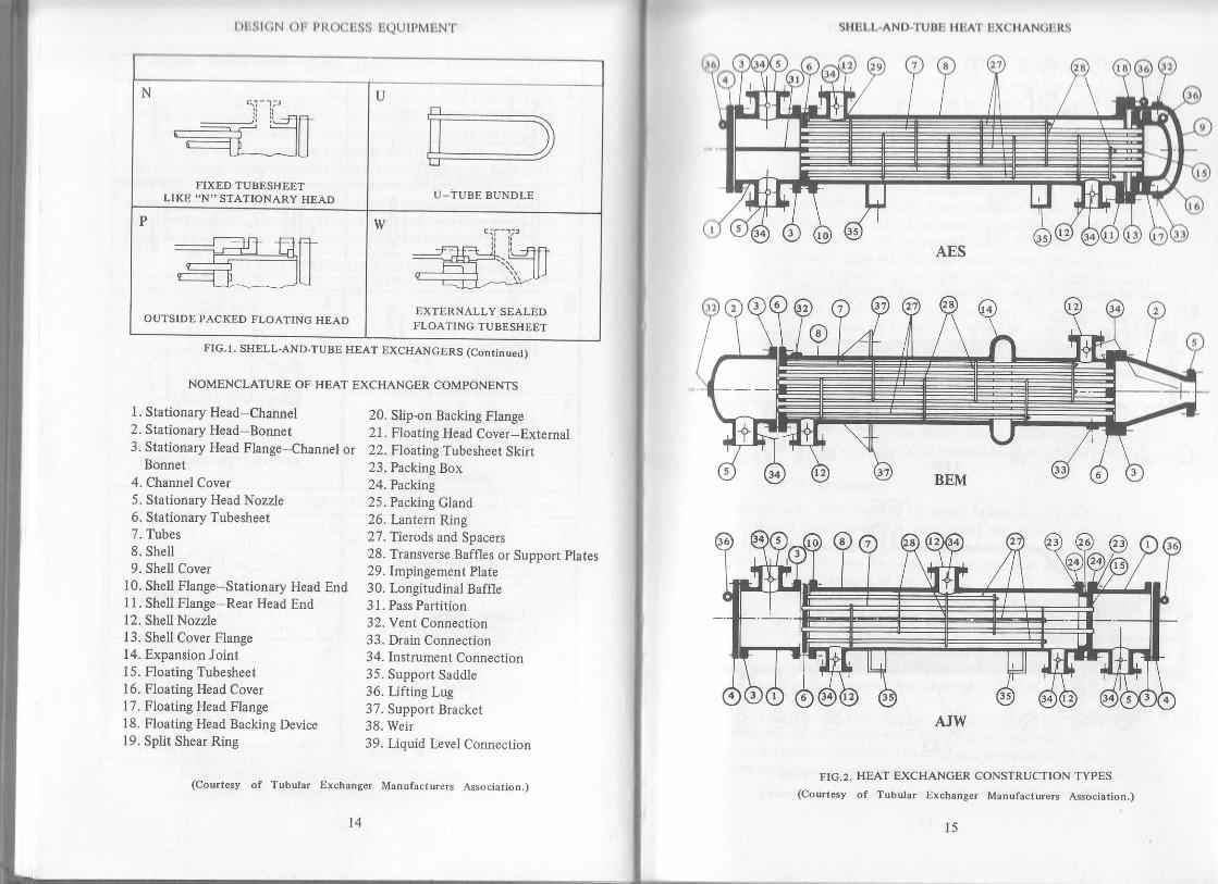
FIG.T. SHELL.AND-TUBE HEAT EXCHANGERS(Courresy of Tubular Exchanger Manlfacturers A$ociation-)
FRONT END STATIONARY HEAD TYPES
CHANNELAND REMOVABLE COVER
N
CHANNEL INTEGRAL WTTH TUBE-SHEET AND REMOVABLE COVER
BONNET (INTEGRAL COVER)
D
SPECIAL HIGH PRESSURE CLOSURECHANNEL INTEGRAL WITH TUBE_SHEET AND REMOVABLE COVER
t2 IJ
w,
SHELL.AND.TUEE HI]AI' TJXCHANCERS
STIELL TYPES
ti
ONE PASS SHELL SPLIT FLOW
TWO PASS SHELLWITH LONGITUDINAL BAFFLE
H
DOUBLE SPLIT FLOW
m nr--l----nLfLr_____ilJ
DIVIDED FLOW
K
KETTLE TYPE REBOILER
X
cRoss FLow
REAR END HEAD TYPES
IFIXED TUBESHEET
LIKE "A'' STATIONARY HEADFLOATING HEAD
WTTH BACKING DEVICE
M
FIXED TUBESHEETLtKE "B" STATIONARY HEAD
T
PULL THROUGH FLOATING HEAD
FIG.r. SHELL-AND-TUBE HEAT EXcHANGERS (Continued)
(Courtesy of Tubular Exchanger Manufacturers Asociation.)
N
FIXED TUBESHEETLIKE "N" STATIONARY HEAD
U
U_iUBE BUNDLE
OUTSIDE PACKED FLOATING HEAD
w
EXTERNALLY SEALEDFLOATING TUBESHEET
l)l1Sl(;N ()lr Pl{()(:liSS l;(.1(,IPMtiN I'
FIG.I. SHELL-AND.TUBE HEAT EXCHANGERS (CONtiNUEd)
NOMENCLATURE OF HEAT EXCHANCER COMPONENTS
SHELL.AND.TUBI] HI.IA'I' IIX(IIIAN(iIJRS
FIG.2. HEAT EXCHANCER CONSTRUCTION TYPES
(Courtesy of Tubular Exchanger Manufacturers Association.)
3. Stationary Head Flange-Channel or 22. Floatine Tubesheet Skirt
l. Stationary Head-Channel2. Stationary Head-Bonnet
Bonnet4. Channel Cover5. Stationary Head Nozzle6. Stationary Tubesheet7. Tubes8. Shell9. Shell Cover
10. Shell Flange-Stationary Head End11. Shell Flange-Rear Head End12. Shell Nozzle13. Shell Cover Flange14. Expansion Joint15. Floating Tubesheet16. Floating Head Cover17. Floating Head Flange18. Floating Head Backing Device19. Split Shear Ring
20. Slip-on Backing Flange21. Floating Head Cover-External
23. Packing Box24. Packrr'g25. Packing Gland26. kntern Ring27. Tierods and Spacers28. Transverse Baffles or Suppod Plates29. Impingement Plate30. Longitudinal Baffle31. Pass Partition32. Vent Connection33. Drain Connection34. Instrument Connection35. Support Saddle36. Lifting Lug37. Support Bracket38. Weir39. Liquid I-evel Connection
(Courtesy of Tubular Exchanaer Manufacturers Association.)
AJW
14 t5

I)l1lil(;N ()lr l'R(X:liSS li(.ltllPMliN f
CFU
AKT
FIG.2. HEAT EXCHANCER CONSTRUCTION TYPES
(Courtesy of Tubular Exchanger Manufactuiers Association,)
16
s Iil,t.-ANl) t.u$ti I.:A,f |]X( t tAN(il,RS
l.'ixed-'l'ubeshcca l.loul llxchangeni
F ixcd-tubcshecl oxcbatrgcrs ilrc [scd n]()rc (ttcn thatr r)y otllcf lyltc.-fhcy have stlaight tubes sccured at botlt onds in tubcshccts wcldcd tothe shell. Usually, the tubesheets extend beyond the shell and scrve ers
llanges lbr bolting tubeside headers. This construction requires t hat shclland tubesheet materials must be weldable to each other.
_ Because -there are no gasketed joints on the shellside, fixed_
lgbesheet exchangers provide maxrmum protection against leakage of5Sellside fluid to the outside. Since clearance betwe; th; oui..rn.r,lgbes and the shell is only the minimum required for fabrication, tubesmay completely fill the exchanger shell. However, this type haslirnitations such as: (a) the shell side cannor be mechanically cleaned orinspected, and (bl t hereis no provision for dillerential therrnut
"iounrronot rne ruDes and the shell. An expansionjoint may be installed in ihe shell1e provide lbr difl'erential thermal expansion, but this req;ir;;;;retuldesign and high quality fabrication, which for large sizes."rufi.,n osubstantial cost increase. Tubeside headers, channel covers, gaskets erc.,are accessible lbr maintenance and replacement, and tu-bes can bereplaced.and cleaned internally. The shellside can be cleaned onll oy6sckwashing or circulating a cleaning fluid.
_. Fixed-tubesheet exchangers tjnd use primarily in services where the
56ellside fluids are nonfouling, such as steam, refrigerants, gases, certainheat transfer nuids, some cooling waters and clean process streams.
g-Tube Heat Exchangers
In this type, both ends of U-shaped tubes are fastened to a singlestationary tube-sheet, thus eliminating the problem ot aifiereitiatllermal expansion because the tubes are free to expand unJ
"o"i.u",.The tube bundle can be removed from the heat ixchanger shell foiinspectron and cleaning or replacement.
The U-tube bundles provide aboul the same minimum clearancebetween the outermost tubes and the inside ofthe shell as fixed_tubesheetexchangers. The number of tube holes in the tubesheet for anv sivcn5hell, however, is less than for the fixed_tubesheet kind becau,ie oflirnitations on bending tubes. The number of tubeside passes mustalways be an even number, the maximum is limited only by ft" nu.U".of return bends.
. Tubeside headers, channels, gaskets etc., are accessible lbrmaintenance and replacement. BundG tube replacement i" ifr"
"r,rt"rows presents no problems. Tlrc others can be replaced only when sDeclaltube supports are used, which allow the U _ tu bes to be spread apart so as
l'1

l)llsl(;N olr Pl{(x)liss [(lulPMtiN'l'
to gain acccss to tubcs insi<lc thc bundlc The insidc of thc tubcs may be
cleaned only with special tools and then only when the bending radius of
the tubes is fairly generous. Because of this, U{ube exchangers are
usually found in non-fouling service, or where chemical cleaning seffective. This construction is widely used for high-pressure applications'
Floating-Head TyPe Exchangers
The floating-head type exchanger is generally preferred in the petroleum
industry because both the tube and shell sides may be inspected and
mechanically cleaned. Also the floating head is free to move, thus
compensating for any di{ferential expansion between tubes and shell
without costly expansion joint provisions. This type is qulte expensrve'
The basic variations are:
Outside-Packed Stuffing Box Fig. 3(a)
In this type, shellside 0uid is sealed by rings of packing compr€ssed
within a stufling box by a packing'follower ring. The packing allows the
floating tubesheet to move back and forth. Since the stufling box only
contacts sh€llside fluid, shellside and tubeside fluids do not mix, should
leakage occur through the packing. The number of tubeside passes rs
limited only by the number of tubes in the bundle Since the outer tube
Iimit approaches the inside of the floating tubesheet skirt, clearances
between outermost tubes and shell are dictat€d by skirt thickness'
Used for shellside services up to 600 psi. and 600"F, these
exchangers are not applicable when leakage of the shellside fluid to the
outside cannot be tolerated.
Outside-Packed Lantern Ring Fig. 3(b)
Here. the shellside and tubeside fluids are each sealed by separate rinls of
packings (or O-rings) separated by a lant€rn ring provided with weep
iroles, so that leakage through either packing will be to the outside The
width of the tubesheet must be suflicient to allow for the two packings,
the lantern ring and for differential thermal expansion A small skirt is
sometimes attached to the floating tubesheet to provide bearing surface
for packings and lantern ring.Since there can be no partition at the floating end' the number of
tubeside passes is limited to one or two. Slightly larger than required for
U-tube eichangers, the clearance between the outermost tubes and the
inside of the shell must prevent tub€-hole distortion during tube rolling
ncar the outside edge of th€ tubesheet.
l8 19
SHELL-AND.TUBE HEAT EXCHANOERS
Outside-packcd, lantern ring units are generally limited to 150 pst.
and 500 F. This construction cannot be used when leakage ofeither fluid
to the outside is not acceptable, or when possible mixing oftubeside and
shellside fluids cannot be tolerated.
Pull-Through Bundle Fig. 3(c)
This type ofexchanger has a separate head bolted directly to the floating
tubeshiet. Both lhe assembled tubesh€et and head are small enough to
slide through the shell, and the tube bundle can be removed without
breaking anyjoints at the floating €nd. Although this feature can reduce
shellside mainlenance, it increases tubeside maintenance. Clearance
requirements (the largest for any typ€ of shell-and'tube exchanger)
beiween the outermost tubes and the inside ofthe shell must provide for
both the gasket and the bolting at the floating tubeshe€t.
The number of tubeside passes is limited only by the numb€r of
tubes. With an odd number of passes, a nozzle must extend from the
floating-head coYer through the shell cover. Provision for both
dilferential thermal expansion and tube-bundle removal must be made
by such methods as packed joints or internal bellows. Since this type of
exchanger requires an internal gasket between the floating tubesheet and
its head, applications are usually restricted to services where never
visible failures of the internal gasket are not intolerable.
Inside Split Backing-Ring Fig. 3(d)
In this design, the floating cover is secured against the floating tubesheet
by bolting to a strong, well-secured split backing-ring This closure,
located beyond the end of the shell, is enclosed by a shell cover of large
diameter. Shell cover, split backing-ring and floating-head cover must be
removed [or the tube bundle to slide through the shell.
Clearances between the outermost tubes and the inside of the shell
(which are about the same as those lbr outside-packed stulling box
exchangers) approach the inside diameter of the gasket at the lloating
tubesheet. This type of construction has the same limitation on the
number of tubeside passes as the pull-through bundle, but is more
suitable lbr higher shellside temperatures and pressures

t)lisl(;N ( )1, l,l((x:l.ss liQt,lPMIN'l
1&_!. Q
9Z
^x
pF(,zF
F
c0>
oo
J
e
d
20
SItIil,I,-ANI).TUBL I It]AT EXCHANCERS
FABRICATION OF SHELL-AND-TUBEHEAT EXCHANGERS
Standards
The TEMA'? (Tubular Exchanger Manufacturers Association) has
published detailed standards for the design and construction of.shell-
and-tube heat exchangers. The mechanical standard has been divided
into three parts rePresenting the following three diflerent classes of heat
exchangers:
l. Class "R" Exchangers This type is specified for the generally severe
requirements of petroleum and related processing applications'
Equipment fabricated p€r this class is designed for safety and
duraLi[ty under the rigoroirs service and maintenance conditions rn
such applications.
2. Class "C" Exchrngers This is specified for the generally moderate
requirements of commercial and general process applications'
Equipment fabricated in accordance with this class isdesigned for the
economy and ove.all compactness consistent with safety and service
requirements in such applications.
3. Class "B" Exchangers This cl4ss is specified for chemical process
service. The equipment is designed for the maximum economy and
overall compactness consistent with safety and service requirements
in such applications.
Fabrication Procedure''s
Shells
The shell portion ofthe heat exchanger is made ofeither seamless pipe orrolled and welded cylinder. These are fabricated from pipe with nominal
pipe diameters up to 12" as given in Table 1. Above 12" and including 24"
the actual outside diameter and the nominal pipe diameter are the same.
Shells above 24" in diameter are fabricated by rolling and welding steel
plates in accordance with the ASME Code Section VIII, Division l, for
Fressure Vessels. Automatic welding is used almost exclusively on the
longitudinal s€ams and also on most of the circumferential seams.

z
z
v
t
F
E]zX()
F'JJ3,.1
z
z
ti$,i
srs *x- l:I* l*,S r,-.l.o.l*.- lE:ellll--l---l'''{.'xEx!
lroo croo laroS,+or l.r IGovr @ o o I u, o .r I t\ r| € | N . , l . , ..'lclc I c?111 !99 l9\e lq , Iooo I ooo I ooo tooo o I
anzLl
lxoo lo-- l.'o l-.- --..6-lo I q|6r I t\ cr ! l{rN- od- loorao ro!l-.r(\ l(\drt I ct.a . l(|at\ 6-c) l!(|N lonlcjcjct | <j<jd I dcj ldctcj cj--'l-.j-'l;ci
*+I lcrovl lol..\ lofl| , , t-oat v)c).o t('.o, ,,lqc': q19 \qlo-- --- F(r
:R| @o({ o.9o crour oc{| ! | t .vtoa -!c| c^-t\ jO-t, ', :!'1,? \qq cqn n.cI ooo oo- --_e --
FJ
FIAU)V)
!tE
tn
z
it
=v)zv)zE
Jt!Fl
F
I ar€(t N-\O -F| , | , oi-r|,, l{l\e qgl q'lI looo o-- -F
vlo.!o I N!6 r -oao \ooo lNv)N ooN, oot\ -66-(\ | {()N, 6O- l'.O- .tN.r OO€ iqr!.r c)-o-- | --e | -(\(! | Nctcr .to{ s)6ro lt\co6loN<jcj<j I cjdcj. cidci | <jctcj cjcicj cicjcj icjcjd l-.i
Ir69lF.!q I l-oo lpo.o lxoc, looo ooo , ooBq-d | !v)N lo!o- lt\O- ldN.,) iooo ooo oooocici I cjcio lood lcicio lodd ldcid cicid cicici
€3I l.oo- oso Lclo. , , !oo9 o.vr4, -.o. , . l<()f) L$!t\ l@o
-i..ii l-i^.i l;^
9O 66- O.('c) O(rr ('\o.o NoolNv)€ PQN !?N.o6o 6-- a{vr o-.\ 6h@ lN.oo !o€ q<9666 :-; l--- (tNN ddN Ir,oi a(lh !'19<jcjct I dcid I cjdo I dcjcj looo ooo ooo loo
!E"*
ooo- | or'lir I on.c I ooo lxoo o.r.r l-.. l-.?€@6 | O-(' | *14' I O-Ci l('rr6 NOF\ NNF. il.\NNooo | --F | --F I Nd(r tN..N .vroo | 66o to.)oood I cjctcj I cjcto I cjcjd lood cjoo lcidd lcj ci cj
qoi('
lr\r\o 6ho odc). ' ' !F.O(.) F\No O\ONI , . . cl .l c? clqa 9n9I OOO OOO OOO
!PoiN
ooo a\N.\| qrqlo' , t lr)v|q) --- l..No
9oI OOO OOCiI ! , i q)vrr, r)vrF
€9,: .! cqc t.iqc? ..i ai l
u)oo 1000loooN66 000looo9\\ qeq teqq(ood {90 0!o(:q9
Siii;2
tttllss ls st I,l-Eat ta{ol' ttt69 ooc,r !t9o o!t0| | 'F t--F .rc||'
sss I sx
22
SIl11t,l,-AND-'I L.lllli HEAT ITXCHAN(;ERS
Flanges
Flanges are designed and fabricated in accordance with the ASME code.Forgings are mostly used to make these flanges. The channel and shellbody flanges require careful facing operations. Flanges made torecognized standards can also be used at the assigned pressure-temperature ratlngs.
Tubesheets and Tube Hole Pattern
Tubesheets are cut either mechanically or with welding torches fromplates or forgings ofdesired materials. Tube holes cannot be drilled veryclose together, since too small a width of inetal between adjacent tubesstructurally weakens the tubesheet. The shortest distance between twoadjacent tube holes is th€ clearance or ligament, and these are now fairlystandard. Four principal tube arrays employed in shell-and-tube heatexchangers are triangular, rotated triangular, square and rotated squareas shown in Figure 4. The triangular arrangement gives the strongesttubesheet for a given shell-side flow passage area, whereas the squarearrangement simplifies some fabrication and some maintenanceoperations such as tubes being accessible for external cleaning. Squarepitch also causes a lower pressure drop when fluid flows in the directionshown in Fig. 4(c). The tube pitch is the shortest center-to-centerdistance between adjacent tubes. The common pitchesfor square layoutsare i" O.D. on l" square pitch and l" O.D. on 1|" square pitch. Fortriangular layouts these are l" O.D. on i*" triangular pitch. In Fig.4(d)square pitch has been rotated 45", yet it is essentially the same as Fig.4lct.
After being laid out in their proper pitch and orientation the tubeholes are drilled in the tubesheet with a slightly greater diameter thanoutside diameter of the tube and then lwo or more slooves are milled inthe wall of the hole.
Baflles
It is apparent that higher heat hansfer coefficients result when a liquid ismaintained in a state of turbulence. Outside the tubes it is customary toemploy ba{Iles which cause the liquid to flow through the shell at rightangles to the axis ofthe tub€s. This causes considerable turbulence evenwhen a small quantity of liquid flows through the shell. The center-to-center distance b€tween balfles is called the baflle pitch or bame spacing.Since the ballles may be spaced close together or far apart, the massvelocity is not entirely dependent upon the diameter of th€ shell. Tierods

l6] 3*:88 1
&trEX
(d)(4,
l)l,Sl( iN ()lrl'lt(X:l.Sli li(l(lll'MIN l
(b) (c)
FIG. 4 - TUBE HOLE PATTERNS
FIG. s ' BAFFLE SPACER DETAIL (Enlarsed) +
Shell flange
Channel flange
ffi*ss-$ 6gmFs88888? *,*ttj\oooooo/ ./
N9-,/-o'ittihg
FIC. 6 - SEGMENTAL BAFFLE DETAIL"
(l,r')rI "l'ft'c{ss l-lcnt Transfer" rv Donald Q. Kern - Copvdghr r9s0I'v Mfl irnw llill ll.x)k Cornprny)
24 25
SHF]LT--AND-'t'UI]F: }IDAT LXCIIAN(;T':RS
are screwed into the tubesheets placcd secttrcly at thc eorrect spacing lor
the given exchanger. Baffles are then slipped onto the tie rods and Iirmly
located in their proper place by use ol spacers between I hem as shou n in
Fig.5.
There are several types of baffles which are employed in heat
exchangers, but by far the most common are the segm€nt baffles as
shown in Fig. 6. Segmental baffles are drilled plates which are general-
ly cut to some percentage of the shell inside diameter' Baffles may be
arranged, ur rho*rr, for "up-and-down" flow or may be rotated 90o
to prJuid" "side-to-side" flow, the later being desirable when a mix-
ture of liquid and gas flows through the shell' The baffle pitch not the
percentage cut detlrmines the effective velocity of the shell fluid'
Other types of bames are the disc or donut, and the orifice baflles as
shown in Figs.7 and 8 respectively. Although additional types are
sometimes employed, they are not of general importance.
Tubes
Heat-exchanger tubes are also referred to as condenser tubes and shouldnot be confused with steel pipes or other types of pipes which are
extruded to iron pipe sizes. The outside diameter of heat exchanger orcondenser tubes is the actual outside diameter in inches within a verystrict tolerance. Heat exchanger tubes are available in a variety ofmetalswhich include steel,copper, admiralty, muntz metal, brass, 70-30 copper-nickel, aluminium bronze, alurninium and stainless steel. They are
obtainable in a number of wall thicknesses defined by the BirminghamWire Gage, which is usually referred to as the BWG or gage of the tube.These tubes are available in various sizes, of which i" O.D. and 1" O.D.are most common in heat exchanger design.
The choice of a tube material for any particular application maypres€nt no problem at all in many cases but may be a dilficult andcomplex problem in severely corrosive envitonments. All the knownfactors which influence or contribut€ to corrosion such as past
performance of materials under similar service condition, type ofcorrosion experienced in similar units, etc. would aid an engineermaterially in selection of most economical and most serviceable tubematerial for the job.
Duplex Tubes
It is not uncommon to find conditions where the fluids both inside and
outside the tub€s are extremely corrosive, and in addition require a
dilferent amount of corrosion on each side. Tubes which combine two

r)rlsl(;N ()lr Pl{(x;liss lxll.J IPML|NT
orific€\[l
r------lirr--1nl(a) Detail
FIG. ? - ORIFICE BAFFLE *
FIG. 8 , DISC AND DOUGHNUT BAFFLE '
O. D. of tubes
FIG. TO
DUPLEX TUBE AND TUBESHEET
JOINT
Donald Q. Kern - Copyrisht 1950
(b)
FIG.9
I)UPLEX TUBE
(lr,'rn '11rxrcss lltl't Transfer"hv M, (;rxw llill lr,xrk (l)mpany)
Doughnut
FERRULE(Same materialas inner tube)
26
SI IELI,.AND.'TUBE HtsAT I]XCHANCERS
differrent metals called duplex tubes can be used to meet this problem'
Duplex tubes are manufactured by mechanically bonding tubes. of two
different metals or alloys so that they are in intimate contact' In this way
it is possible to choose various combinations of ferrous or non-ferrous
alloys to combat successfully a certain type of corrosion at the^outside
surface and entirely different type of corrosion at the inside surface'
Ferrules
Where contact of the ends of th€ outer tube with the fluid passing
tfriough tlt" toUe isconsidered objectionable, these ends may be replaced
with flrrules of the same alloy as that of the inside tube' These ferrules
need be only long enough to ensure their b€ing held in place when the
tube ends are rollid into the tubesheets' It is a distinct advantage to have
iil."-1".tut". furnished as an integral part of the tube to facilitate
ir,.Lttutiott. The construction of duplex tubes with attached ferrules is
shown in Fig. 9 and 10 before and after installation respectively'
Tube Rolling
Tubes are passed through the tubeshe€ts and baffles, and are fixed in
place by an expanding operation. They are set in a preliminary.fashion
Ly forcing u piog ug"intt the tubes. The plug preYents the tube from
turning when the roller expander is inserted' The roller is a rotatrng
mandr-il having a slight taper. It is capable ofexceeding the elastic limit of
the tube metai and transforms it into a semiplastic condition so that it
flows into the grooves and forms an extremely tight seal A simple and
"ornrnon ""u.ll. is shown in Fig. 11. Tube rolling is a skill,since a tube
-rv- U. Ou-og"O by rolling too thin and leaving a seal with little
structural strength.
FI6. 1T . TUBE ROLL
(From "Process He.t Transfer"by Mccraw-Hill Book ComPany)
FIG. I2 - FERRULE
Donald Q. Kern ' Copyright r95O
27
TurningSlot \
Tube wall

l)lisl(;N olr Plt.( )(il'lss llQtrlPMuN'l
ln some industrial uses it is desirable to install tubes in a tubesheet
so that they can be removed easily as shown in Fig. 12. The tubes are
actually packed in the tubesheet by means of ferrules using a soft metal
packing ring.After completion ofthe bundle assembly, it is brought to a test rack
where a hydrotest is applied. Bundles are then lowered vertically into the
exchanger shells and linal hydrotest of the exchanger is made. After the
outside ofthe shell is painted with a rust-preventive paint and all flanges
are covered to prevent damage, the unit is ready for shipment.
Design of rnajor shell and tube heat exchanger components is
illustrated in the examples given below.
EXAMPLE NO. 1
Usinghand calculation method, mechanically design all the components ofacarbon steel, 56 inch inside diameter having 16 feet long tubes, TEMA'AET" type of shell and tube heat exchanger for the following conditions.
Design Pressure, Psig
Design Temper'ature,'FCorrosion Allowance, In.Number of Passes
SHELL SIDE TUBE SIDE50 420
400 250Va '/a
l4
Provide solid soft steel gasket at the floating head and steel j acketed asbestos
gaskets at all otherjoints. Use ASME Section VIII, Division l6 and TEMA"R" design criteria in calculations. Also, check the reinforcement require-
nrcnt for an 8 inch 300# R.F. nozzle on the tubeside.
28
sllDl,l--ANl)-ltJttli llliAl lix( l{AN(il:Rs
DESIGN CAI,CULATIONS
Shell Cylinder
Reference: ASME Section VIII, Division 1' Paragraph UG-27(c)
P = Design Pressure, Psig : 50 PSig
n = C..t A"i inside radius, in. = 28 125 in'
J : eilo*uuf" stress at design temperature' psi = 13'800 psi
E = Welcl joint efficiencY : 85
C.A.: Corrosion allowance, in : .125 in'
Now
t = Minimum cylinder (hickness' in'
PR: >* C.A.SE _ ,6P
_ 50(28.125) _i .12513s00(.85) - .6(50)
= .1202 + .125 : '2452 in , use 72" (SA-285-C)
Shell Cover CYlinderReference: same as shell cylinder
5O(28.t25) + .2513300(.85) - .6(s0)
: .1202 + -125 : '2452 in , use /2" (SA-285-C)
Shell Cover Head (2:1 ElliPsoidal)
Reference: ASME Section VIII, Division l' kragraph UG-32(d)
P : Design Pressure, Psig : 50 Psig
R : Corr;ded inside radius, in = 28 125 in'
S : Allowable stess at design temPeratue' psi = 13'800 psi
E = Weld joint efficiency = '85C.A. = Corroiion allowance, in = 125 in'

l)liSl(;N ( )lr I'l{(XilrSS lQtJlPMIN'l'
Now
r = Nominal head thickness, in.
PR
st - .lP
50(28.125\-F .125 + .u025
13800(.85) - .1(s0)
: . i 199 + .125 + .0625 - .3O'14 in., use 26" nom. (SA-285-C)
Chann€l Cylinder
Reference: Same as shell cylinder
420(28.125\t =
-+
C.A.17500(.8s) - .6(420)
: .8078 + .125 = .9328 in., use 1" (54-516-70)
Channel Flanges at Cover and Thbesheet
Reference: ASME Section VIII, Division 1, Paragraph UA-48
Welding neck flanges are used in design. Both channel flanges will beidentical as they are independent because tube side design pressure isconffolling the design.
Referring to the nomenclature, figures, tables and design steps forindependent hub flange in chapter 2 and using SA- 105 flanges and SA-193-87 bolts, we have
p : 420 psiS' : 25'000 PsiS" = 25,000 PsiSr" = 17,500 psiSr" = 17,500 psi
Also in uncorroded condition8:56in.
80: t': l0in'Assume
gr : 1.5(go) = 1.5(1.0) = 1.5in.Thus in corroded condition
B : 56.25 in.8" : 875 in'
SHTJI,I--AND"TUBE HEA'I' T.:XCTIAN(itJRS
itn(l
8r : l '375 in
Nowh : 1.5(eo) = 1.5( 875) : 1.3125 in. (min'), use 2'25 in'
k, - 2^l (1.375 - R75)(rone =E ---:------------- = o.2222 < 0.333h 2.25
Therefore, the flange can be designed as an integral type as shown in
Fig. 1a of Chapter 2. Now assume (64) lVt in. dia. bolts. From Table 3. inChapter2, for lVq in. dia. bolts, we have
R : 1.75 in.E = 1.25 in.
Nowc = B + 2(g t) + 2(R'):56.25 + 2(1.375) + 2(1.75) = 62.s in-
andA: C + 2(E) = 62.5 + 2(r.25) = 65 in.
Gasket and Bolting Calculations
From lhble I in Chapter 2, for an iron jacketed asbestos filled gasketm = 3.75
andv : 7600
AssumeN = 0.625 in.
Fig. la. of Table 2 in Chapter 2,applies to our situation. So,
A/ n 6t56 =:::: = 0.3125 in.22Therefore
Vb^ Vc.:t sh :
-:- : U.L|YJ n.-22
NowG : C - a - 2(0.25) - 2(b) : 62.s - 1.2s - 2(0.2s) - 2(2195)
= 60.191 in.Assume rib area : RA : '{0.7018 in.2
Therefore W.r: 10.2795 (n) 60.191 + .5(40.7018)l 7600: 556,344 lb.
Ho = 12 (n) 0.279s(60.19r) + 40.70181 3.7s(420)
= 230'590 lb.
3t

l)lisl(;N ( )tr plt(x:liss uQUlpMtrNT
1tIt = -(60.1910), 42o = t,t95,097 tb
W^, = |,195,097 + 230,590 = 1,425,68l. tbthus
. r,425.687
". =J5poo = 57.0275 in.z
From Table 3 in Chapter 2, the root area of a 1 ya in. dia. bolt having g threadsper inch is .929 in.2 which gives
Ao = 64(.929) = 59.456 tn.2
Since A, ) A-, therefore (64) lVq tn. dia. bolts are adequate. Now
W : 0.5 (57.02'15 + 59.4s6) 25,000 = r,456,044 rband
.. (59.456) 2s.000
'"-t =zrr?oooioo.rsl = o5l7l in
Since N > N-r, therefore chosen gasket width is adequate.
Flange Moments Calculations
HD:- \56.25)2 42O = 1.043.j23 tb4
H6 = Ho = 230,590 lbHr= 1,195,097 - |,043,723 = t5t,3j4 tbhp:1.75 + .5(1.375) = 2.4375 n.hc= .5 (62.5 - 60.191) : t.1545 in.hr=.5 (r.75 + 1.375 + 1.1545) : 2.1398 in.
Mo= 1,043,723 (2.4375) : 2,544,07 5 in-tbMc = 230,590 (1.154s) = 266,216 in-IbMr:151,374 (2.1398) : 323,910 inlb
Mo = 2,544,0'15 + 266,216 + 323,910= 3,134,201 in-lb
Now, for the gasket seating condition
Now
Therefore,
Hc: W : 1,456,044lb.
33
SHELL.AND.TUBE HEAT EXCHANGERS
'l'hcrclurc,
Mo = 1,456,044 (1.1545) = 1,681,003 inlb
t(O tr(62.5\Actual bolt spacing =-: 64 = :.00S in.
Assumet:5.0625in.
Miximum bolt spacing = 2(1 .25) + *9 ^ : g.e+l in.(J. /J + U.)'
Normal bolt spacing : 2(1.25) + 5.0625 = 7.5625 in.
Since, Actual bolt spacing ( maximum bolt spacing, the chosen bolt spacingis O.K. and also actual bolt spacing < normal bolt spacing, the correctionlactor CF = 1.0.
'I'hus, the calculation factors are
" ='u#-= 55.ite
tu t.681.003 ( t.0)
56.25
Deiermining Shape Constants
Z:1.8565z = 6.9647Y : 13.487 |
U:14.8209Now
L = r.57l48o
fr\
^ : _ --:l= l.t))o)b.zi
From Table 4 in Chapter 2, for rK : 1.1556
29,884
and
ho :\6r.25.r;, = 7.0156

l)Hst(;N ( )tr PR()cEss EQUIPMENT
h=2.25: ^rnho 7.0 t56
From Fig. 4 in Chapter 2, for
P, h" - 1.51 t4 and - = .320i8o ho
we have
F = 0.8736
Similarly from Fig. 5 in Chapter 2,
V = 0.3488
and ftom Fig. 8 in Chapter 2,
f = r.20r9
0.8736p =-: l)A\- 7.0156and
14.8209d : laRR
(7.0156t (.875)2 = 228.2333
Calculating Other Stress Factors
c = 5.0625 (.1245) + | : 1.63
B =14 \s.oozsr.l245) + t= l.E4\ 3/I .63
^, =-= R7R,' 5.062s
- (5.0625)3d =-= .5685
i: .8782 + .5685 = 1.4467
Calculating Stresses
Operating Condition
^ 1.2019(55.719)," :lZOt,r:tsr, = 24,484 psi <26,250 psi O.K.
SHELL.AND-TUBE HEAT EXCHANOERS
r.84( 55.719).S,, = ---- = 2,765 psi <17,500 Psi O.K.
| .4467 (5 .0625)2
ss Trorl? aRTl\s,. =-#- 6.9647(2,765) = 10,064 psi <17,500 psi O.K.'' (5.0625)'
Sincc S, > S^, there fore, 0. 5(24,484 + 10,064) = 17,274 psi < 17'500 psi
o. K.
(;ssk€t Seating Condition
1.20r9{ 29.884)s- =€= l3.l32Psi >26.250 Psi O.K.
1 .446'1 ( | .37 5\2
1.84(29.884)S- =-- = 1.483 Psi <17.500 Psi O.K.
1.4467(5.0625\2
29.884(13 .487 l)s.,, =::j:=-: :: - 6.964i (1,483) = 5,398 psi <17,500 psi o.K.''' (5.0625t2
Since
s. ) s.,
therefore,
0.5(13,132 + 5,398) : 9,265 psi <17,500 psi O'K.
All stresses in both the operating as well as the gasket seating conditions
are within allowables. Thus, the inde_pendent flange design is O.K.
Next we will discuss the design of the shell side or the dependent
flange.
Shell Flange at Tubesheet
Refer to Figure and design steps on weld neck dependent flange design
calculation sheet in Chapter 2. Here we have
P = 50 psi
Since, the flange and bolt materials are the same as for the independent
flange, the values of Sr, S- S" and St remain unchanged. Noq in the
uncorroded condition
^ -r -n <i-60 - ', - v.J 'u.
8r = 0.8125 in'
Assume

and
l)tist(;N oF Pt{o(iEss EQUTPMENT
Thus, in the coroded condition
8r : 0.6875 in.Assume
h = 2.0 in. > 1.5 Go)> 0.5625 in. O.K.
ro 6R?5 - n 17slSlope :--: .1563 <.J33 O.K.' 2.O
Therefore, the flange can be designed as an integral flange as shown inFig. la of Chapter 2.
Since, both the flanges are to be bolted together, the number and size ofbolts, and diameten B, C, G and A will be the same as for the independentflange. Also, the values ofn and y will remain unchanged since thi gasketmaterial is the same.
The value of radial clearance R will be greater than the minimumrequired for this flange, because its bolt circle dia. C has to match the boltcircle dia. of the independent flange and its g, is smaller than g, of theindependent flange. So in this case
R _ c - lB + 2(8 )l =A5 - 156.25 + 2(0.6875t1
z ----;- = 2 4315 in'
Gasket and Bolting Calculations
The width and the effective width of the gasket will be the same as forthe independent flange. Now
W^za : 556'344 IbHo : 2n (.2795) 60.191(3.75) 50 : 19,820 lb
H = 160.191.t, 50 : 142,273
W^r* = l'425 '691lb'
which will result in the same A. as earlier, thus I7 will also be the same.
Flang€ Moments Calculations
H" =X66.zs)2 (so) : 124,zszrb
*The values of Wu I and W-2 are taken ftom independent flanse
SHELL.AND.TUBE HEAT EXCHANCERS
H<;=W^t-H=l'425,691 - 142'273: l '283 '411
IbHr = 142,273 - 124,252 = 18,021 lbho : 2.4315 + .5(.6875) : 2.7813 in'hc : .5(62.50 - 60.191) = 1.1545 in.
hr= .5(2.4375 + 6875 + 1.1545) :2.1398 in
Nrtw
Mp = 124,252(2.7813) = 345'577 in-lbM c = r,283,4r7 (1. 1545) : l'481'718 inib
Mr = r8,02r(2 1398) = 38'561 inlb
'l'hcrcfore,
Mo : 345,577 + 1,481,718 + 38,561 : 1,865,854 inlb
Now, for the gasket seating condition
Hc=W: l'456'045 in-lb
'l'hcrcfore,
Mo : 1,456,M5( 1.1545) : l'681'019 inlb
A$sume
t : 4.8125 in.
Normal bolt spacing will be greater than the actual bolt sPacing , thus Crt.0.
Thus, the calculation factors are
lnd
u:ffff=zz,nr
r'r ={Se: zr,tss
I)etermining Shape Constants
since the value of f is the same as in the independent flange the values of Il, Y and U will remain unchanged.
Now
L=@: r.srrsLo 0.375
ho =\/s6.2s(0.37 s) = 4.s928

r)Esl(;N oF PR(rcESS EQUIPMENT
h:2'o : o.+zssho 4.5928
From Fig. 4 in Chapter 2 for grl80 = 1.8333 and hlho : 0.4355 we have
F : 0.8442
Similarly from Fig. 5 in Chapter 2
V : 0.2671
and from Fig. 8 in Chapter 2
Now
and
f = 1'2179
0.8442e =-= 0.1838
4.5928
14.8209d =
0.26j [email protected]) (0.375)'z : 35.8386
Calculating Other Stress Factors
cr = 4 8125(0.1838) + I = 1.8846
p :( r )a.8l2s(0.1838) + I :2.t794
r =@: t.ot:t' 1.8565
(4.8125)l; =-: J.ii- 35.8386
I: 1.0151 + 3.11 = 4.1251
Calculating Stresses
Operating Condition
- |.2t79(33,17t) ^,S.. =
-
= 20.720 psi <26.750 psi O.K.4 .1251(.687 5)2
^ 2.1794(33,171) ^,s^ =
-:
/57 psi <17.500 psi O.K.4 . t251(4 .8125)2
38
SHELL.AND"TUBE HEAT EXCHANOERS
s, -1U{114!D - 6.s647(7s7) = 14,047 psi <17,500 psi o.K'(4.8125)2
SinccS. > S^'
llrcrclbre.o.5 (20,720 +14,047):17 ,383 psi< 17,500 psi O'K
(;o8ket Seating Condition
t,, =4H9= 8,667 Psi <26,25oPsioK'4 .1251( .687 5\2
. 2.1794(29,88s) -^^S.. = ___________- _: 6EZ psr <17,500 psi O.K.^ 4.125'(4.8t25)2 '
. 29,885(r3.4871).\... = ----------------- - o.vo,+r(682) : 12,655 psi <17,500 psi O'K'' (4.8125\2
Sinces. ) s^,
lhcrefore,0.5(18,667 + 12,655) = 15,661 psi <17,500psi oK'
All the stresses in both the operating as well as the gasket seating
conditions are within allowables, thus the dependent flange design is O'K'
Additional desired thickness for raised face, counterbore, tongue or
lroove should be added to the calculated thickness / to obtain the final total
thickness of the flange In the above example we added %o in. to the
thickness of each flange Jor counterbore.
(lhannel Cover
Rcference: TEMA hragraph R-8.2, ASME Section VIII, Division l, Para-
graph UG-34(c)
P: Design pressure, psig = 420 PsigG = Mean gasket diametel in. = 60.191 in.
d,: Norninal bolt diameters, in. = 1.25 in.h" : Radial distance betwe€n mean gasket diameter and bolt circle, in'
= 1.1545 in.A,: Actual total cross-sectional area of bolts, in.z = 59.456 \n'2
i : Required channel cover thickness at the bottom of the pass partition
groove, as determined by the TEMA equation or the appropnate
ASME code equation. whichever is greater, in.

r )tjtit(;N ()tr t,R(xIiss ti.ltJ ,MINT
('.r'1. - Cornrsion allowancc or dcpth ol pass partition groove, whichever isgreater, in. : .1975 in.C = A factor for method of cover attachment = .3
S., = Allowable stress for cover materi2l ar ar-^.^r.-,;^ ,---^-^...-_
^ : 17,500 psi naterial at atmospheric temperature, psi
J"o : Allowable stess for cover: 17,500 psi material at design temperature' psi
E : Elastic modulus of cover material at design temperature, psi: 28.4s(10)6 psilV : Design bolt load for sasket
w-, : legu_,r9g
bort road ror "0"#l';":"::?fl,i:' rb = r,4s6,044 rb
= 1,425,687 tb
TEMA Equation
,=l*y".r#y1,, + cA
_lt -422-$0.l9l)4 420+0.5(t.1545) 59.456(60.t91) l06 j,,t ,^L 28.45( 10)6 28.45( t0)6 t/i$ - J
+ l87s
= 7 .1744 in.
ASME Equations
Operating Condition
t=G cP r.9lw_,) h-
r- *.;;* to'
= 60.191
= 5.5177 in.
Gasket Seating Condition
- /t.9twh-t=U., l a+aAV s., (ct, - "'
= 60.191 C.A.
: 1.9288 in.
TEMA F4uation Conhols: Use 7.25 in. thk. (5A-516-70)
17.s00 (60.191)3
| .9fl,456.044) 1.ts4517,s00 (60.19t)3
sHttlL-ANt),',t ulrlt IiAI Ix(]]tAN(]trRs
'lbbesheet
l{cference: TEMA Paragraph R-7.1
P = Design pressure, psig = 420 psigS : Allowable stress for tubesheet material at design temperature, psi
= 17,500 psiG: Mean gasket diametet in. = 60.191 in.F: Tirbesheet constant : 1.0 (for tubesheets having straight tubes)
C.A. : Shell side corrosion allowance plus tube side corrosion allowance ordepth ofpass partition groove, whichever is greater, in. = .3125 in.
Now7 : Effective thickness of tubesheet, in.
FG Tp:iv;*_ 1.0(60. 191)
2+ .3125
C.A.
= 4.6624 + 0.3125 : 4.9749 in.
Use 5" thick tubesheet (5,4-516-70)
Notes: (l) Ihbesheet thickness for bending only is calculated and it isassumed that shear does not control the desisn.
(2) Floating tubesheet will have sma er valui of G but bothtubesheets of the same thickness are used.
Floating Head
Reference: ASME Section VIII, Division l, hragraph l-6 & Appendix 5
P: Intemal design pressure, psig = 420 psigPc = Extemal design pressure, psig = 59 nritS" = Allowable bolt stress at atrnospheric temperature, psi = 25,000 psiSr: Allowable bolt stress at design temperature, psi = 25,000 psi
Sra = Allowable stress for flange material at atmospheric temperature, psi: 25.000 osiSn: Allowable stress for flange material at design temperature, psi
= 25,000 psiSrr = Allowable stress for head material at design temperature, psi
= 17,500 psiC.A. = Shell or tube side corrosion allowance, in. = .125 in.
41
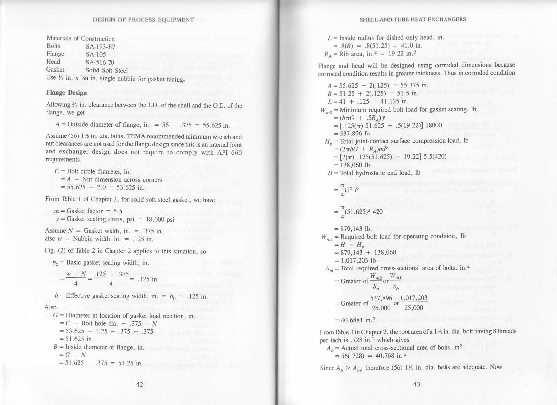
DESIGN OF PR@ESS BQUIPMBNT
Materials of ConsnuctionBolts SA-193-87Flange SA-105Head 5^4-516-70Gasket Solid Soft SteelUse 7r in. x 7a in. single nubbin for gasket facing.
trlange Design
Allolving % in. clearance between the LD. of the shell and the O.D. of theflange, we get
A = Outside diameter of flange, in. = 56 - .375 = 55.625 in.
Assume (56) I % in. dia. bolts. TEMA recommended minimum wrench andnut clearances are not used for the flange design since this is an intemal jointand exchanger design does not require to comply with ApI 660requirements.
C : Bolt circle diameter, in.=A - Nut dimension across comers:55.625 - 2.0 = 53.625 in.
From Table I of Chapter 2, for solid soft ste€l gasket, we have
n = Gasket factor : 5.5) = Gasket seating stress, psi = 18,000 psi
Assume N = Gasket width. in. = .375 in.also w = Nubbin width, in. = .125 in.
Fig. (2) of Table 2 in Chapter 2 applies to this situation, so
bo = Basic gasket seating width, in.
w+N .125 + .375: .125 in,
D = Effective gasket seating width, in. : bo : .125 n.Also
G = Diameter at location of gasket load reaction, in.= C - Bolt hole dia. - .375 - N= 53.625 - 1.25 - .375 - .375= 51.625 in.
I = Inside diameter of flange, in.:G_N= 51.625 - .3?5 = 51.25 in.
SHELL.AND.TUBE HEAT BXCHANOENS
L = Inside radius fo( dished only head, in'=.8(B) = '8(51.25) = a1.0 in.
Rr = Rib area, in.2 = 19.22 in.2
Flange and head will be designed using corroded dimensions becguse
conoded condition results in greaier thickness. Thus in corroded condition
A = 55.625 - 2(.125) = 55.375 in'B = 51.25 + 2.\.125') = 51.5 in.L= 41 + .125 = 41.125 rn.
W., = Minimum required bolt load for gasket seating, lb
= (bnG + .5Ra))
= [.12s(tt) 51.625 +.5(19.22, 18000
= 537.896 lbIl, = Total joint-contact surface compression load, lb
= (2ttbG + R)mP:12(tr) .r2s(51.62s) + 9.nls.s@n)= 138,060 lb
Il = Total hydrostatic end load, lb
=loct p
= -.(5r.625)2 420
= 879,143 lb.W-r = Required bolt load for operating condition, lb
=H+HP: 879,143 + 138,060
= 1,017.203 lbA,, : Total required cross-sectional area of bolts, in.2
^ ^W,a W^r: Urearcr oI -:-or-;-J" J,
_ _537,896 t,Ot7 203= Great€r d ztmo - zsooo
= 40.6881 in.2
From Table 3 in Chapier 2, the root area ofa I % in. dia. bolt having 8 threads
per inch is .728 in.2 which gives
Aa = Actual total ooss-sectional area of bolts, in2
= 56(.728) = 40.768 in.2
Since A, ) A-, therefore (56) l% in. dia. bolts are adequate. Now
l' n
DEStcN oF PROCESS BQUTPMBNT
W = Flange design bolt load for the operating condition or gasket seat_ing, as may apply, lb
= .5(A^ + A) S"
= .5(40.6881 + 40.768) 25,000= r,018,201 lb
and
.lf-, : Minimum required width of gasket, in.
:Aus"2ryG
_ 40.768(2s,000)
2r(18,000) 51.625
: .1746 in.
Since N) N,,r, therefore chosen gasket width is adequate.
flange Moments Calculations
11o = Axial component ofmembrane load in the spherical segment actingat the inside of the flange ring, lb
:!8, p4
1T
= -(51 .5)2 420
= 874,890 lbIlc = Gasket load in operating condition, lb:Ho
= 138,060 lb1{. = Difference between total hydrostatic end force and hydrostatic end
force on area inside of flange, lb:H-Ho:879,143 - 874,8m= 4,253 lb
Ilr = Radial component of the membrane load in the spherical segment,tb
_- f v_4L, - B'r _ _^^f vai.nf=,7;rv1:""L- a I =874,8e0L--=;:J: I,089,471 lb
44 45
55.375 - 51.5
SHBLL-AND.TUBE HBAT EXCHANOERS
io = Radial distance ftom the bolt circle to the inside of the flange ring,m,
=.5(C - a) = .5(53.62s - 51.5) = 1.0625 in.ic = Radial distance from gasket load reaction to the bolt circle, in.
= .5(C - G) = .5(53.62s - 51.625) = 1.0 in.frr = Radial distance from bolt circle to circle on which Ii. acts, in.
=,s(hD + he) = .5(1.0625 + 1.0) = 1.0313 in.hn = I-ever arm of force 11^ about centroid of flange ring, in.
=0 in.
Now
Ma = Moment due to I/r, in-lb=Hoho = 874,890 (1.0625) = 929,571 in-lb
Mc = Moment due to llc, in-lb= He hc = 138,060(1.0) : 138,060 in-lb
Mr : Moment due to I1r, in-lb= Hr hr = 4,253(1.0313) = 4,386 inlb
Mn = Moment due to llR, in-lb: Hn hn = 1,089,471(0) = 0 in-lb
Mo : Total moment acting upon the flange for the operating condition, in-lb
=MolM6+Mr+MR=929571 + 138,060 + 4,386 + 0: |,072,017 in-lb
Mt:Mal moment acting upon the flange for the gasket seating, in-lb
:WC: 1,018,201(1.0) : 1,018,201 in-lb
Flange Thickness Calculations
Intemal hessure
P8\,6I;-;8S&(A - A)
4206r.s\v4(4r.125)2 - (5 1.5)2
8(17s00) (55.37s - 5l.s)
=2.557
M.o/A+B:"+(^-"= 32.81
) =;iff#ft( 55.375 + 51.5
DESIGN OF PROCESS EQUTPMENT
, = Rcquilgg_qEe thickness for opcrating condition, in.=F +\/F7=2.557 +\EmTffir = 8.83 in.
, = Required flange thickness for gasket seating condition, in.
#;"r->
= 5.5821 in.
Extemal hessure
p :YoG, p,
:f,u.azsl,5o = ru,66o lb
no:!SP r"
=itsr.sy so : lo4,l53 rb
Hr=H - Ho= 104,660 - 104,153 = 507 lb
hp"= ho - h6= 1.0625 - 1.0 :
hre: hr - hc= 1.0313 - 1.0 =
ha=oMo= Ho ho,
: 104,153(.062s) =
.0625 in.
.0313 in.
6,510 in-lb
= t*,'slfV{4€#l : r2e,6e8 rbL 5t.5 I
1,018,20r,,55.375
5l i(lr5oo)(553?5
46 47
SHELL.AND.TUBE HEAT EXCHANOERS
Mr= H, hr"= 507(.0313) = 16 inlb
Mp: Ho h^:129,698(0) = 0 in-lb
Moe = Ibtal moment acting upon the flange due to extemal pressure, psi
=Mo*M,rM*=6,510 + 16 + 0 = 6,526in-lb
p.B\/trL - B,
8 Sf" (A - B)
50(51.5) v4(41.12s\2 - 51.52
8(17500) (55.375 - 51.5)
= .3044
J =Moe1e + n
B S/"\A - B
6.526 .,55.375 + 51.5=
sr J(r?Joor(5si?s - sl.s:0.20
t : Required flange thickness for extemal pressure, in.
:F +!F2 + l= 30da f/(304o2 + .?I : .8454 in.
Thus the flange thickness for operating condition controls. Adding %o in. forcounterbore and ys in. for shell side corrosion allowance, we get,
Total thickness of flange= 8.83 + .1875 + .125
= 9.1425 in., Use 9.25 in.
Ilead Thickness Calculations
Intemal Pressure
/azr = Minimum required thickness of head plate, in.
_ .833 PL
sl{
.833(420) (41.125)= 0.8222 in.. sav 0.875 in.
17,500
Extemal Pressure
tno = 0'875 in'L = 41.125 in.

t)t.:st(;N ( )tr t,t((xltjss lt(lrJ ,MtjN,t.
Lltt , = 41.1251.875 = 47A = Code factor to obtain B
, .125 .. .l2s:{* l= * =.0021\LnHD/ +r
From ASME Section VIII, Division l, Appendix 5, Fig. UCS-28.2
B = 13,900P" : Maximum allowable external pressure for bead, psi
/ B . 13.900=l* l_-=2e5psi\LlrHD/ +r
Maximum allowable pressure Po is greater than the extemal design pressureP" of 50 psi thus the head thickness is adequate.
Total.head thickness =,r/D + shell side C.A. + tube side C.A. * formingor thinning allowance: .875 + .125 + .125 + .125: 1.25 \n. nominal thk.
Calculation of Reinforcement for Thbe Side Nozzle
Reference: ASME Section VIII, Division l, paragraph UG-37 and Appen_dix L
P = Design pressure, psig = 420 psigC.A. : Corrosion allowance, in. = .125 in.
R : Conoded inside cylinder radius, in. - 28.125 in.R,: Corroded inside nozzle radius, in. = 3.9375 in.d: Corroded inside nozzle diameter, in. = 7.g75 in.
Er = Channel cylinder joint efficiency : 1.0E: Nozzle neck joint efficiency : 1.0S: Allowable cylinder stress at design temperature, psi = 17,500 psi
S": Allowable nozzle stress at design temperature, psi = 15,000 psit: Corroded cylinder thickness, in. = 0.875 in.
t,: Corroded nozzle thickness, in. : 0.375 in.S, : Allowable reinforcing pad stress at design temperature, psi
:17,500 psi
s- 15.000"/,, = (max = 1.0)=-=.8571J 17,500
f..r = (lesser of S, or Sp)/S (max - 1.0, = -!f, - ttt'I /,)UU
sHIit-1.-ANI)-ltJBli I tAt lixcltAN(itsRs
17.500(max = 1.0):-:1.0
17,500
a = Outward nozzle weld leg size, in. : 375 in.
F : Correction factor = 1.0
t,: Required cylinder thickness, in.
PR
sEt - .6P
_ 420(28.r2s) :0.6849 in.17500(1.0) - .6(420)
/,,- Required nozzle neck thickness. in.
: PR"
s"E - .6P
420(3.931s)= u. r rZr rn.
15000(1.0) - .6(420)
A = Area of reinforcement required, in.2:dt,F + Zt"t,F (1 - f,r):7.87s(.6849) (1.0) + 2(.375) (.6849) (1.0) (l - .8571)
= 5.467 in.zA, = Excess area in cylindet in.2
: Larger of the following: d(EJ - Ft,) - 2t, (EJ Ft,) (.1 - f,)= 7.875 {l(.875) - l(.6849)} - 2(.375){l(.875) - l(.6849r(l -
.8571): 1.4767 in.z
of:2(t + t.) (Ert - Ft.) - zt"(EJ - Ft)(l - f,)= 2(.875 + .37s) {l(.875) - l(.6849)} - 2(.375) U(.875) -
l(.6849)) (l - .8s71): .3369 'n.2
42: Excess arca in nozzle, in,2: Smaller of the following:5(t" - t,") f1 t= 5(.375 - .1121) .8571(.875)
= .9858 in.2or
:5(t"- t,")fit,=5(.375 - .1121) .8571 (.375)
49

DESIGN OF PROCESS EQUIPMENT
: .4225 in.zAr = Area of outward nozzle weld
= (a)2 fa= (.375)2 (.8571) : .1205 in.2
Total available area of reinforcement : A, -t A, ! Ao:1.4767+.4225+.1205= 2.0197 in.2
Since Ar + Az+ A4<A, use additional reinforcement
Additional arearequired : A - (At + A2 + A4)
= 5.467 - 2.O197 = 3.M3 rn,-z
Try 15.5 in. O.D., .5 in. thick SA-516-70 pad thus , Dp : outside diameter otreinforcing pad, in. : 15.5 in. and, t, : reinforcing pad thickness, in. = .5in.
Check with rtinforcing pad added
A : Area of reinforcement required, in.2
= 5.467 in.2
Ar : Excess area in cylinder, in.2: |.4767 in.z
A, = Excess area in nozzle, in.2
= Smaller of the following: s(t" - t,") f^ t:5(.37s - .1121) .8571(.875)
=.9858 in.2 or:2(t" - t,") (2.5t" + t") f,l= 2(.37s _ .rt2t) {2.5(.37st + .5} .8s71: .6478 in."
A., : Area of outward nozzle-to-pad fillet weld: ta)z fa: (.375)2 (.857l) : .1205 in.2
Let c = hd to cylinder weld leg size, in. = .375 in.Aor: Area of pad to cylinder fillet weld
= (c)z f,z= (.375)2 (1.0) = .1406 in.2
As : Area of reinforcing pad:(DD_d_2t)tef5: (15.s - 7.875 - .75) .5(1.0) : 3.4375 in.z
Total available area for reinforcement = Ar + A2 + A4r + 442 + As
= 1.4767 + .6478 + .1205 + .1406 + 3.4375 = 5.8231 in.2Since area a\ailable for reinforcement is greater than area requircd, theopening is adequately reinforced.
50 )l
SHELL-AND.TUBE HEAT EXCHANOERS
EXAMPLE NO.2
Using hand calculation method, design a fixed tube sheet for a TEMA"NEN" type of shell and tube heat exchanger for the following data:
Shell
20 in. O.D., Carbon Steel (4-106-8), % in. thick
Mean Shell metal temperature = 298"F
Tbb€s
( 284, 3/4 in. O.D., 14 BWG min. wall, 12 ft. long
Carbon Steel (A-214)
Mean tube wall metal temperature = 288'F
lhbe Sheet
Carbon St€el (A-516-70)
Mean tube sheet metal temperature = 2147
Design Conditions
Design Pressure, PsigDesign Temperature, 'FCorrosion Allowance, In.Number of hsses
Use TEMA "R" and ASME Section VIII, Division 1 design criteria forcalculations . Assume that there is no shell expansion joint and check to see ifone is required.
DFSIGN CAI,CULATIONS
Fixed Thbesheet
Reference: TEMA Paragraph R-7ASME Section VIII, Division 1, UG-23(b) & Appendix 5
Ps = Shell side design pressure, psig = 75 psig
P, = lhbe side design pressure, psig : 130 PsigDo = Outside diameter of shell, in. = 20 in.
SHELL SIDE75
360Y8
I
TUBE SIDE130
200Y8
1

ff1
DESIGN OF PROCESS EQUIPMENT
do = Outside diameter of tubes, in. = 0.75 in.," = Corroded shell thickness, in. = 0.25 in.,r ='IUbe wall thickness, in. : 0.083 in.G: Corroded shell I.D., in. = l9.5in.N = Number of tubes = 284E": Elastic modulus of shell material at metal temperature, psi: 28.21(10)6 psi
4= Elastic modulus of tube material at metal temperature, psi= 28.26(10)6 psi
E : Elastic modulus of tubesheet malerial at metal temperature, psi= 28.63(10)6 psi
d" : Coefficient ofthermal expansion of shell material at metal tempera-ture, in./in. "F : 6.596(10)-6 in./in "F
a, : Coefficient of thermal expansion of tube material at metal tempera-ture, in./in. 'F = 6.576(10f6 in./in. "F
O" = Shell metal temperature - 70"F = 228'FO, = Tub" metal temperature - 70"F = 218"F
Mr = Total flange moments in operating condition, in- lb = 0M2 = Total flange moments in gasket seating condition, in - lb= 0
F = Thbesheet factor : I (for tubesheets with straight tubes)J: Rctor : I (for shell without expansion joint)S = Allowable tubesheet stress at design temperature, psi = 17,500psi?= Assumed thickness of tubesheet, in. = 1.25 in.Z = lbbe length between inner tubesheet faces, in. = 141 in.
D; = Expansionjoint inside diameter, in. = 0 (since there is noexpansion joint)
Now
,, E" t" (Do - t")
Et\N (4 - t)
=@=.,..28.26fl0)6 (.083) 284 (.75 - .083)
1300 r. E- ,G, 31ttaF.= .25 + (F - .6) l=:-{;l IL KLE \t/ J
" ?rn/ ?s) 28.21(10)6 zl9.5ri-lt/a ^ ^^:.25+t-.6t1--l.rrsrr+rr-e-orffi (,*) I
: 3'62
P, : Equivalent differential expansion pressure, psi
_ 4./ E, t" (oc" O" - a, O,)
(Do_3t")(t+JKFq)
4(r) 28.21(10)6 (.2s) [6.s96(10)-6 (228) - 6.
[20 - 3(0.25t [1 + (1) .3135 (3.82)]
SHELL-AND.TUBB HEAT EXCHANOBRS
= 216.89 psi
Pr, = Equivalent bolting pressure when tube side is under pressure' psi
= u ?- ',t = o (since M, = g;
(n2 (G)3
Pr" : Equivalent bolting pressure when tube side prcssuro is zero' psi
= 6'? M"-:
o (since M" = g;(n2 (G)3
forir,s * rrr.t,L- +/")) - :J(e'
(t + .lKF q\
_ 75r.4(1) u.5 + .3135 (1.5 + .5799)l - 5 = 29.379 osi-L 1+l(.3135)(3.82) IP = Effective shell side design pressure, psi (will be the greater absolute
value of the follorings)
P=.5(P"' - P) = .5(29.379 - 46.89) : - 8.76psiP =P: = 29.379 psiP=Pas=0P=.5(P! - Pa- Pns) = .5(29'379 - 46.89 - 0) = - 8.76 psi
P = .S(Pas + P7) : .5(0 + 46.89) = 23.45 psi
P : P"' - Pes = 29.379 - 0 : 29.379Psi
The maximum absolute value of effective shell side design pressue will be
29.319 psi.
Now
f"=t-"fo)':1-2s4(4,J2:.Siee
P! = P
f,=1-*(+')J
DESIGN OF PROCESS EQUIPMENT
r.75 - 2 (.083Ir 'z=l-284l-ler I =.74s
Since P,' is positiveP = Effective tub€ side design pressure, psi (will be the greater absolute
value of the followings)P =.s(Pi + PE, + P) = .5(75.87 + 0 + 46.89) = 6l.38psiP = Pt! + Pat : 75.87 + o = 75.87psi
Thus the effective tube side pressure will be 75.87 psi
T : Requircd tubesheet thickness
FC IF2y s
Where P is tlle gxeater of effective shell or tube side design pressure
= ''[uffiffi@]:zs'sznsr
r(rg.5\ EE2 V l75oo
= .642 in., use 1.25 in (min.) + shell side C.A. + greater of tube side C.A.or groove depth
or use r = 1.25 + .125 + .125 : 1.5 in. (54-516-70)
It is O.K. to \se ly2 in. thick since tubesheets thicker than computed arepermissible provided neither sheU nor tubes are overloaded.
She[ Longitudind Stnecs Calculations
Pr -Pr - P,'= 130 - 75.87 = 54.13 psi
P,* = Pr = 54.13 Psior P,* =p I - 29.379 psiorPr+= - Pa = - 46.89psior Pj* = Pr + P"' = 54.13 + 29.379 = 83.5 psiorPr*:Pr - Pa = 54.13 - 46.89 = 7.24 psior Ps:* =Ps' - Pa = 29.379 - 46.89 : - 17.511 psi
or Prt =Pr + P"' - Pd = 54.13 + 29.379 - 46.89 = 36.62 psi
Using maximurn positive value of P"* we have
54 55
SHELL.AND"TUBE HEAT EXCHANCEN,S
Cs = 1.0 (from TEMA kragraph R-7.22)Ss = Maximum effective longitudinal shell sness
_ (D. - r") (C" P"'*)
4t"
_ (20 - .25) (l) (83.5)
4(.2s)
= I,649 psi (tensile)
S" (allowable) = 15,000 psi (tensile)
S" < S, (allowable), shell is O.K. in tension
Using rnaximum negative value of P"t we have
C. = 1.0 (from TEMA Paragraph R-7.22)
(20 - .25\ | //'6.89).
4(.25'l
: 926 psi (compressive)
A= .r25 | (DJzt"): .125 t (2O1.5) = .003l
From ASME Section VIII, Division l, Fig. UCS-28.2B : 14,900
S" (allowable) = B = 14,9000 psi (compressive)
S, <S, (allowable), shell is O.K. in compression
S.: shell material yield stress : 35,000 psi
.9is") = .9(35,ooo) : 31,5oopsiLs(E) : L5(1649) : 2,474 psi1.5(S,) <.9(s'), shell is O.K. at hydrostatic test
Tube Longttudlnal Stress Calculatlon
p, = p,' -+@) = 7s.87 -#(130) = 50.52 psiF q ' 1.8:.
P. : P-' -Lrr-, = zg.37g -ft99Fq " ';(75)
= 17'99 nsi
P,* = Pr. : 50.52 Psior Pr* = - Pr: - 17.99 Psior P,a : Po = 46.89 Psior P,* : P, - Pg : 50.52 - 17.99 : 32.53 Psr

rDBSIGN OF PROCESS BQUTPMENT
ot P,r = p, + Po = 59.52 + 46.89 = 97.41 psiot P,4 =-P3+Pd: -17.99 + 46.89 = i8.9psior P,* = p, - P3 + Pd = 50.52 - 17.99 + 46.89 =Using maximum positive \alue of P,* we have
C, = 0.5 (From TEMA hragraph it-7.23)S, = Maximum effective longitudinal tube stess
_ Fo G2 Ct Pt+
4N4@o- t)3.82 (19.5)2 .5 07.4tl
4(284) (.083) (.7s - .083)
= 1,125 psi (tensile)
S, (allowable) = 10,000 psi (tensile)
S, < S, (allowable), tubes are O.K. in tension
Using maximum negative value of P,+ we have
C,:1.0 (from TEMA kragraph R-7.23)
^ 3.82 (19.5\2 | (17.99\
'' = +,2g4) ("08ilJ5:ls3): 416 psi (compressive)
: lhbe maierial yield stress : 26,000 psi: Radius of glration of tube
: 0.25Vdo2 + (do - 2r)z
= 0.25 V.75)2 + t .75 - .t66)2 : .2376 in.
79.42 psi
.s,r
K
kt
= Maximum unsupported tube span= 60 in. (span between two baffles)= 1.0 (For unsupported span between two baffles): Equivalent unsupported buckling length of the tubes: 1(60) = 60 in.
IGFE.vs.
kl 60
r .2376
2(n)2 28.26(10)6
26,000
5657
SHELL-AND-TUBE HEAT EXCHANOERS
Since c" JS. = Allowable tube compressive stress
_ tP E, _tr2 (28.26)106=r@y= ,eoLory : 3'417 Psi
\r,S, (allowable) = smaller of S, (allowable) in tension or Sc
= 3,417 psi
S, <S, (allorvable). tubes are O.K. in compression..9(S,) = .9(26,000) : 23.400 psL
1.5(,9) = 1.51a161 = 624psi1.5(S,) <.9(SJ, tubes are O.K. at hydrostatic test
Calculatlons of TubeToTubesheet Jotnt Loadg
P,* = Pt: 50.52 PsiorPr*=-Ps=-17.99psior P,* = P, - Pz = 5O.52 - 17.99 = 32.53 psi
Pr* = 50.52 psi (Greater absolute value of the above)
Now
W; = Maximum effective tube-io-tubesheet joint load
1l= ;; Fo P,* (G)2
: ar3.82l so.sz eg.5t24(284')'
:203 lbA, : Nominal transverse cross-sectional area of tube wall
= .7854 f do2 - (do - u,)21L-l
:.78s41 .7s2 - (.15 - .166)2) I = .1739 in.zLJ
- Allowable tensile stress for tube material at design temperatue , psi
= 10,000 psi
= hctor for the length of the roller expanded portion of the tube
= 1,0 (For joints made with roller expanded tubes in grooved tubeholes)
,(

I )rist(;N ( )tr t,l{( x:lis:i ltlutPMtN't
/;. : Pactor for reliability ofjoint= 0.70 (for rolled joints having two or more grooves)
4, : Ratio of tubesheet yield stress at metal temperature to the tube yieldstress at metal temperature or 1.0, whichever is less, for rollerexpanded joirts
= 1.0
17, (allowable) = Maximum allowable tube-lo-tubesheet joint load
= A, (s") f" (f) fy: .1739 (10,000) l (0.70) I= | ,217 lb
17, <lV, (allowable), tube-to-tubesheet joint is O.K.
All the stresses are within allowables therefore, the tube sheet design isadequate and expansion joint is not required.
REFERENCES
l. Morton, Donald S., "Heat Exchangers Dominate Process HeatTransfer," Chemical Engineering, June ll,1962, pp. 170-176.
2. Standards of Tubular Exchanger Manufacturers Association, 6thEdition. 1978. New York.
3. Lord R. C., Minton P. E., and Slusser, R. P, "Design of HeatExchangers," Chemical Engineering, J anruary 26,1970, pp. 96 -l18.
4. Rase, Howard F., and Barrow, M. H., "Project Engineering of ProcessPlants," John Wiley and Sons, Inc., New York, 1957.
5. Kern, Donald Q., "Process Heat Transfer", lst Edition, McGraw-Hill Book Company, New York, N.Y., 1950.
6. ASME Boiler and Pressure Vessel Code, Section VIII, "Pressure Ves-
sels," Division I, ASME, New York, N.Y., 1983.
58 59
2
FLANGE DESIGN
The flange is the most essential part of pressure vessels, heat
cxchangers and storage tanks. Flanges are used on the shell ofa vessel ori|n exchanger to permit disassembly and removal or cleaning of internalparts. Flanges are also used for making piping connections and any
other nozzle attachments at openings.The ASME Boiler and Pressure Vessel Code permits, and even
cncourages, the use of flanges made to recognized standards such as
"Steel Pipe Flanges and Flanged Fittings," ANSI 816.5, 1973 or 19'11
cdition. Flanges conforming to this standard can be used without
calculation at the pressure-temperature ratings assigned in 1977 edition.
Certain other standards, however, that are not nearly as well
known, also provide designs which may be lound acceptable,
particularly in the sizes above 24" which is the upper size limit of the
ANSI 816.5 standard. Thus, it is often possible to find in a recognized
standard the exact flange type, size and material ne€ded for a particular
application.The following are typical flange standards:
MSS SP-44 was developed to establish uniform flange dimensions for
use with high pressure pipe lines of26" through 36" size, and classes 300
through 900. It is now revised to include class 150 and sizes 12" through
60'.
API (American Petroleum Institute) Standard 605, Large Diameter
Carbon Steel Flanges, 75, 150 and 300Ib rating in sizes 26" through 60"
inclusive.
Taylor Forge Standard, classes 75, 175 and 350 in sizes 26" through 72"'
92" and 96" respe€tively.
ii

t)tist(;N ( )t t,t{(xjiss l1(?lIIt,MIrNI.
AWWA (Anrcricarr Watcr Works Association) Standard C207-55.classcs B, D and E, in sizes 6" through 96".
The flanges included in the API Standard and the several TaylorForge Standards are designed in accordance with the requirements ofthecode. When flanges to other standards are considered, only allowableratings in accordance with the code need to be checked instead of thedevelopment of an individual design.
Taylor Forge Catalog No. 722 lists all of the above and also otherlarge diameter flanges. A lot of unnecessary flange design time can besaved by choosing the appropriate flange from this catalog. Howevcr,due to the variety of sizes and pressure and temperature combinationsrequired for process equipment, manual designing ofthese flanges is notvery uncommon. The design analysis of various types of flanges alongwith the sample design calculations for eash kind are included in thischapter.
We will cover the design ofcircular flanges under internal pressure withgaskets entirely within the inrer edges of the bolt holes and with the outerrims of the flanges not touching under the applied loading as discussed rnASME Boiler and Pressure Vessel coder and EPG Bulletin No. 502,2 Thescare classified as circular flanges as illustrated in Appendix 2 of 1983 editionof the ASME code Section VIII, Div l, Paragraph 2-4 and Fig. 2-4. Thefollowing are types of such flanges:1 Int€gral Type Flanges. This type covers designs where the flange rs
integral with the neck or vessel wall, butt-welded to the neck or vesselwall, or attached to the neck or vessel walt by any other type of weldedjoint that is considered to be the equivalent to an integral structure. Inwelded construction, the neck or vessel wall is considered to act as ahub.
Fig. la through ld represent flanges of this type. For flangcshaving tapered hubs, the dimension 9o is defined in the code as thehub thickness at the small end, but for calculation purposes it is moreconvenient to let go equal the wall thickness of the attached cylinder.Also, th€ hub length I extends exactly to the point where its slopelinemeets the O.D. of the vessel or nozzle and thus ft may actually beshorter or longer than the hub length as manufactured.
The dimension B in this case will be the inside diameter of boththe flange and the vessel or nozzle.
2- Loose Type Flanges. This type covers designs where the flange hasno dir€ct attachment between the vessel or nozzle and those wherethe method of attachment is not considered to be equivalent rointegral structure.
60 6l
Irl.AN(il; l)rlsl(;N
l-ig. lc shows the original application of this type. The hub canho made of any length or omitted entirely. B€sides lapjoint, slip on,threaded and socket type flang€s are also classed as loose typ€. Forhubbed flanges ofthis type, there is no minimum limitation on i or go.
I{owever, values oI go less than 1.5t, and i lcss than go are notrecommended. Ifthe hub is too small to meet these limits, it is best todesign it as in Fig. 1f, but ofintegral type, using hub thickness equal to(t r + t,) at large end, t, at small end and B as the inside diameter ofthevessel or nozzle.
While designing loose type flanges, B should be taken as the
inside dianeter of the flange but not the vessel or nozzle.
Optional Type Flanges. This type covers designs where the
attachment of the flange to the vessel or nozzle wall is such that theassembly is considered to act as a unit which should be calculated as
an integral flange, with the vessel wall taking on the functions of the
hub. This obviously includes welded construction with no apparenthub, as shown in Fig. 1g and lh, or constructions with such smallhubs that do not merit inclusion in the loose typ€ group. The term"optional" is used because the designer may calculate the
construction as a loose type flange provided none of the followingvalues is exceeded:
B .^^,o:i Incn. ..i
:J(^J
Design pressure :300 psi
Operating temperature : 700"F
Thus the integral flanges that come within the above restrictions
can also be designed as loose type flanges. This simplifies the calcula-
tions and may result in som€ economy.
BOLT LOAD AND GASKET REACTION
In bolt-up condition the bolt load is balanced only by the gasket
reaction as shown in Fig. 2a. As internal pressure is applied, the boltload is balanced by lhe sum of gasket reaction and the hydrostatic end
force due to pressure as shown in Fig' 2b. Thus, while designing a
flange, both the above conditions should be analyzed separately.

INTEGFAL TYPE FLANGES TOOSE TYPE FLANGES
whete Hub Stope Adiacen! To FlangeE ceeds 1:3 Use Dataits (1b) ot (1c)
f. 8. tu1., At Nii-p.irt Ot Carocr B.-1..., n@0. Ard Lop t.d.p.nd.nt Of
OPTIONAL TYPE FLANGES
| ^=-,4Fu Pcr.r.o ;A Ba.k.hle I
Loodlnt And Dlhutto.s At. fha SoD. As
FIG. I . TYPES OF FLANGES(Courtesy of Energy Produds croup)
62 63
lrl.AN(ili l)l1Sl(;N
Itr.qrir(d llolt Lords
{rl lflet Disc-Type Gaskets: Operatirg Conditions
llrt: r'cquired bolt load, tIl.r, shall be sufficient to resist the hydrostaticr'|l(l li)rcc, H, exerted by the internal pressure on the area bounded by the
,lrrrrrrctcr of gasket reaction G, and, to maintain on the gasket or joint-, {,ntircl surface a compression load. tl, Thus'
w^t:H+He::G2P+2bncn? (l)
llolt-up or Gasket S€ating Condition
lkrlilrc a tight joint can be obtained it is necessary to seat the gasket or
ro!nt-contact surface properly by applying a minimum initial load, l/,r,wr tlrout the presence of internal pressure. This load is a function of the
prrskct material and the effective gasket area to be seated and can be
r'U)rcSSed aS:
W^z:brGY
FIG.2a
(2)
FIG' 2b
FIG. 2-BOLT LOAD AND CASKET REACTION
(Courtesy of Energy Products Group)
tk.w
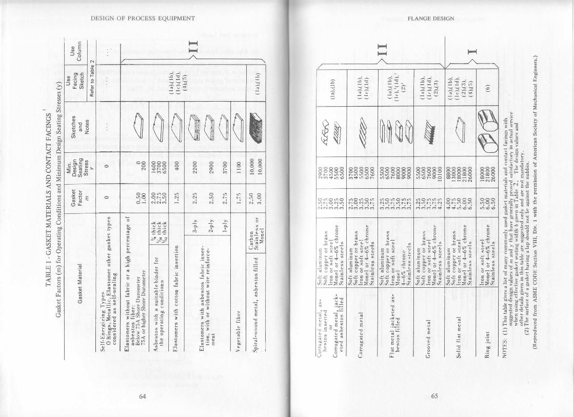
l.t.AN(iti Dl1st(;N
,:
'd
?.Y
iE>iE .;
; I *r E
5i+;, *:Ei i€ s:tj. E?.iE:{:i E
i i+ rz L
-3FE I, IiE.s i ; IErrij I;h.:::'
z=E !.= A5!E ti ;F='d:
=- >,+!: >
): ti 5 iE7i-, a= i *!! c;: i;; F:E:'9n ar!g=t= E
1'r' vE I <;€;E+ E
f $E!! ;F d } OF U
Fvcz
3,
F
-^*:i3i'^ ^
$M mftumsE
R?RC9 83338
h u-.:>e
-;36s?: c o\o q,
! Ed : ;
::5 o- di.ti.:=i
coo ,ae:a. =7.
6 " oir:?::6 6i o,i.,i.:> +i
! -o : ;
::5 5'!.i.d,:> e
:o,Y3E*.i=3
::5 5 (!i.,i:>6
E
,r. =
ii
F F';=i,i.
]. Ya6 .:=
E;-E9
-1 i:
6564
o
F
ts
=I;
!o Eyc7-9'Z
5a$#' g
iisd'j:
;ts
.= 3-;r,,ib
Jo 3
.9
o i9
J -o
=9:-.o o-< !l: O;:E
tE:6rr1
t
- !.n
cc.
3i
-'ai93
!l
3P
?.aiE
t )lisr(;N olr Pl{(xtLss LQUTPMEN'I'
-azt4a
<rr21
z1<E<F
<tFC
<!F .iJ

FLANGE DESI(]N
/:b
i;
5>:5
.-E .:
a>
2A;= L
?: r,tT: Ez7 a
a^ !
vll
*:=+i+tdj o:< r! ce{'s i.9 E= o
E r;: ; 1"s"{!!: !r, t o L-E
Ei;*:i[; EI
l-'-*' ;.$| (,*II
cl']i l-"'lc
67oo
l)lrsl(;N ()F PI{O(ILSS tiQUIPMENT
--\
al+ l'+
{:..-sj"+ 16l
-l-l
\z$
ZF
=lg-
- l^r^l
-l< l.rvtl
INiNNRB-{1tzN'|| rtrtlrl_'t]*1.r_
,=
z
;
z
aIv
FT
,Fr{M
E]
FH
El
3
F
T+
ZN
,i
Ftil{Ff
laF3N
$z

t)list(;N ( )tr pR(xitiss l]Q(itpMI]NT
For flange pairs having a tubesheet in the middle as in exchangerapplication or for any other similar application wher€ the flanges andor gaskets are not the same, W^, shall be the larger of the valuesobtained from above formula as individually calculated for eachflange and gasket, and that value shall be used for both flanges.
Code suggested values of gasket factor ,|| and minimum designseating stress / for various gaskei materials are tabulated in Table Iand effective gasket seating widths for different contact facings aregiven in Table 2.
(b) Self-energizing Gaskets: Operating Conditions
The required bolt load for the op€rating conditions, t/,,, shall besufficient to resist the hydrostatic end force, H, exerted by the internalpressure on the area bounded by the outside diameter ofthe gasket. H, isto be consid€red as zero for all self-energizing gasket except certainseal configurations which generate axial loads which must be con-sidered.Bolt-up or Gasket Seating Condition
Self-energizing gaskets may be considered to require an inconsequen-tial amount of bolting force to produce a seal. So ttl.2 can be assumedequal to zero. Bolting, however, must be pretightened to provide abolt load sufficient to withstand the hydrostatic end force I/.
Determination of Bolt Area
If S, denotes the allowable bolt stress at the operating temperature,and S, the allowable bolt stress at atmospheric temperature, thenthe minimum required total bolt area,4- is obtained as follows:
. w^, w^A.: !' or '2. whicherer is greaterJn J,
Selection oibolts to be used shall be made such that the actual totalcross-sectional area of bolts, lr, will not be less than 1.. Excessrvebolting may have to be provided while designing relatively thin flangesfor low pressure service because of the following,
l. Due to the danger of over-stressing smaller size bolts duringtightening, a minimum bolt size of /z " is usual in most piping andpressure vessel work,
2. For practical construction reasons, bolting is mostly provided inmultioles of four.
6869
trt.AN(;li I)|]st(;N
I lk)lts must be spaced close enough to assure adequate gasket pressurel)clwcen bolts.
Seltction of Bolt Spacing
lhc minimum bolt spacing based on wrench clearances limits therrrrrrrbcr of bolts that can be placed in a given bolt circle. The maximumlxrll spacing is limited by the permissible deflection that would existlr('twocn flanges. If the deflection is excessive, the gasket joint will leak.lil'(i Bulletin 502 "Modern Flange Design" recommends the followingfrrrpirical relationship for maximum bolt spacing:
Bolt spacing (maximum):2a +. 6-L' (m + 0.5)
l,lstsblishing Bolt Circl€
I lrc thickness of hub at back of flange g, should first be calculated asIr)llows:
g L: 1.25 g o to 2.590
Table 3 lists the root area, minimum bolt spacing, radial distancerrd edge distance etc. as functions ofbolt size. The minimum bolt-circletliirnreter will be either the diameter necessary to satisfy the radial
' lcirrances,i.e. B * 2(tr + R) or the diameter necessary to satisfy the bolt-rpircing requirement,i.e. N(Bolt spacing)/z, whichever is greater. The,rptimum design is usually obtained when these two controllirrg(lr meters are approximately equal.
l,'lange Design Bolt Load, W
lhc bolt loads used in the design of the flange shall be the values()btained from the following forrnulas:
For operating conditions
W:W^,For gasket seating
t 4,-r Ab\5.u,:. .^ i g)
ln formula (4) S, shall not be less than that tabulated in Subsection C ofthc ASME Section VIII, Division t code. In addition to the minimumfcquirements for safety formula (4) provides e margin against abuse ofthc flange from overbolting since margin against such abuse is neededplirnarily for the initial, bolting-up operation which is done at
(3)
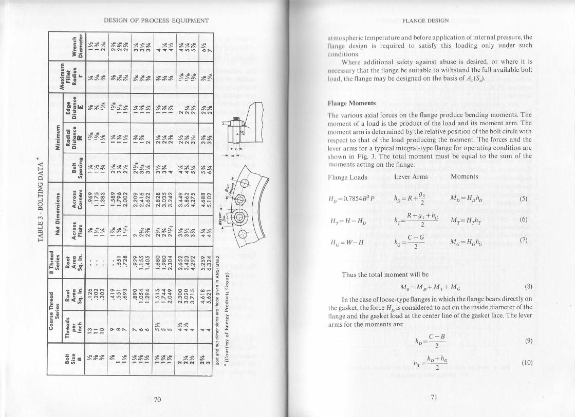
|)tist(;N otr PR(xtuss tiQtjlt,MUN'I'
F
ztrFI
J
F
6z:<i
6(,
5dFE]E*:.
€!5Ei3
sN{ sNs ssN ss sss s
a
.E!€ -ioJ
s*s sss SSs ssx s:s;s s5
tE
T
o
& Er,r,!.E
ossF 5ss sss sss ss xs
z2!!aE6
55s sss ss sss sxs sx
o
3l sss Sss 5Ss SN sNs NS
otz
!j na9 ci ct rt atc,t{
EEiE
sss sxs ss sN5 sss ss
!!rotsi; !Eid<;' nqc?
c.i t't .q kt <t
;.PoI
EEid<;' qqc! 9\q a?c\ 99
i.: t\94s ss
=o3#" sxs ss sxs xxs ss x
a.i.:s-
70
lrl.AN(;li I)l1Sl(;N
.r | || rr rrl)llcric tcnrpcta(t||c ltrd bcforc applicatiott tlf intcrnal pressure, thellrrrrgc tlcsigrr is rcquircd to satisfy this loading only under such( ll (lrll()lls.
Whcrc additional safety against abuse is desired, or where it ts
r( ( cssirt y that the flange be suitable to withstand the lull available boltl, rrrrl. t hc llange may be designed on the basis of .4r(S,).
lilurge Moments
I lrc various axial forces on the flange produce bending moments. Therrrorlcnt ol a load is the product of the load and its moment arm. The
Ir()l|tcnt arm is determined by the relative position ofthe bolt circle withI rsllcct to that of the load producing the moment. The forces and theI vcr arms for a typical integral-type flange for operating condition are
',lrown in Fig. 3. The total moment must be equal to the sum of thenr()u)cnts acting on the flange:
I lrr nge Loads
rt,,:9.195432 o
ll,:H-11o
Il,:ltY-g
Lever Arms
hr:n+i
, CG
Moments
Mr: Hoh,
i/, -u L
Thus the total moment will bc
Mo: M D+ Mr+ Mo (8)
ln the case of loose-type flanges in which the flange bears directly on
rhc gasket, the force Il, is considered to act on the inside diameter ofthellange and the gasket load at the center line of the gasket face. The lever
irrms for the moments are:
, C.B"2
t" _hp+ hc
2
'71
(e)
(10)
, R+ gt+ hc"r- 2
(5)
(6)
(1)
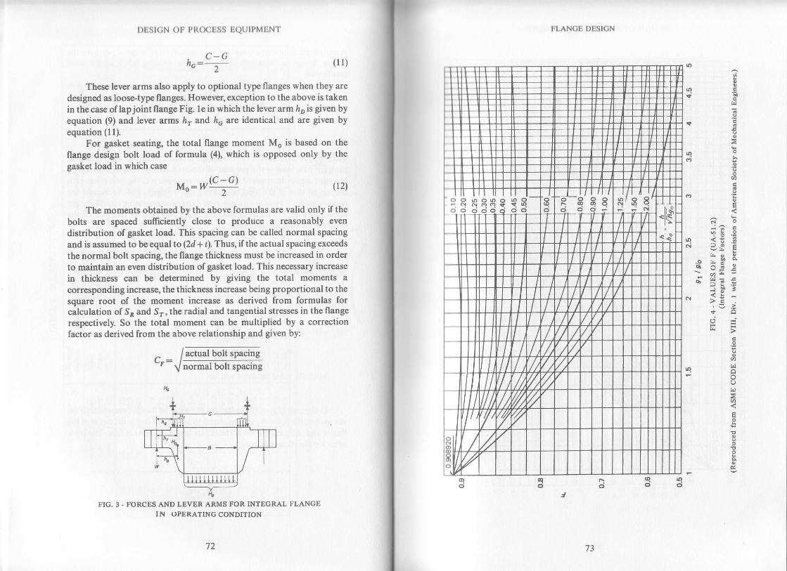
I)llsl(;N ()lr l,l{(xil-ss li(.ltJll'MliN f
h.:= (ll)
These lever arms also apply to optional type flanges when they are
designed as loose-type flanges. However, exception to the above is takenin the case of lapjoint flange Fig. 1e in which the lever arm ho is given byequation (9) and lever arms lrr and lo are identical and are given byequation (11).
For gasket seating, the total flange moment Mo is based on theflange design bolt load of formula (4), which is opposed only by the
gasket load in which case
Mo:I'Yq:G) ir2)
The moments obtained by the above formulas are valid only if the
bolts are spaced sufliciently close to produce a reasonably even
distribution of gasket load. This spacing can be called normal spacing
and is assumed to be equal to (2d+ t). Thus, ifthe actual spacing exceeds
the normal bolt spacing, the flange thickness must be increased in orderto maintain an even distribution ofgasket load. This necessary increase
in thickness can be determined by giving the total moments a
corresponding increase, the thickness increase being proportional to the
square root of the moment increase as derived from formulas forcalculation of S^ and St, the radial and tangential stresses in the flange
respectively. So the total moment can be multiplied by a correctronfactor as derived from the above relationship and given by:
^ / actual bolt spacingtr: a/ 116rmar uort .spacins
FIG. 3 - FORCES AND LEVER ARMS FOR INTEGRAL FLANGEIN OPERATINC CONDITION
'ra 73
trt.ANCll l)tisl(;N
ii t
-o l.E" I- ;tr i
'rP 3<! -
'a ...'

E
o
u)
3E3 '-i
PE
.3- :g
o
d
o P9
; !5- vE
6i !+<9>9,'i
o
lrl -AN(;li I)liSl(;N
''oooo o o.o(o €dr N _qq9c? n'co@sc) N - ooooo :33 33 3E
-do c; ci oo-J
E
3 ,no SB 3ci oOo ci
7574
Itl:Sl(,N ()l l,ltrx:l SS tirlll ,MtlNt
,1
E
6
E
35 3
^ >d 5
: cas E
.rI 3
>r -.: !- ,u
o
3
'.q
o
A
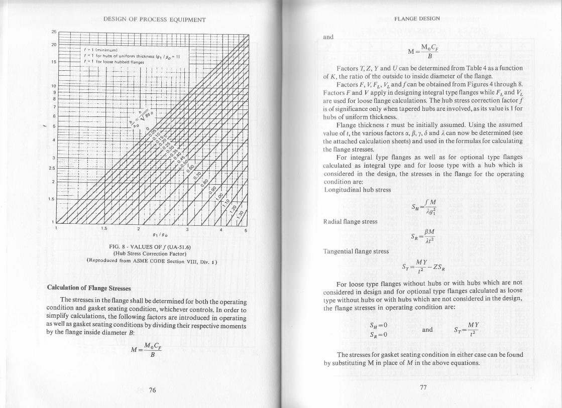
I )list(;N otr pt{(xjliss IiQtJtpMuN'1.
Frc. E _ VALUES OF/(UA-51.6)(Hub Stress Correction Factor)
(Reproduced from ASME CODE Section VIII, Div. t )
Calculation of Flange Str€sses
.The stresses in the flange shall be determined for both the operating
condition and gasket seating condition, whichever controls. In order tosimplify calculations, the following factors are introduced in operatingas well as gasket seating conditions bydividing their respective momentsby the flange inside diameter B:
M:MocrB
76 77
it ||(l
trl.AN(iu l)lisl(;N
M : MocrB
l{adial flange stress
,-:0!-" fu2'I angential flange stress
.MY-^5-: ., _ ZSj'1
For loose type flanges without hubs or with hubs which are not
considered in design and for optional type flanges calculated as loose
type without hubs or with hubs which are not considered in the design'
the flange stresses in operating condition are:
MYand S": ,'t'
Factors T. Z. y and U can be determined from Table 4 as a functionol K, the ratio of the outside to inside diameter of the flange.
Factors F, \ Fr,Vrandf canbe obtained from Figures 4 through 8.
l,irctors F and Iz apply in designing integral type flanges while F" and I/,rrlc used for loose flange calculations. The hub stress correction factor jfis of significance only when tapered hubs are involved, as its value is I forhu bs of uniform thickness.
Flange thickness t must be initially assumed. Using the assumed
value of r, the various factors c, B, y, d and ,t can now be determined (see
thc attached calculation sheets) and used in the formulas for calculatinglhc flange stresses.
For integral fype flanges &s well as for optional type flangesctlculated as integral type and for loose type with a hub which is
considered in the design, the stresses in the flange for the operatingcondition are:l.onsitudinal hub stress
sI| fM: .-2^gr
Sa:0Sr:0
The stresses for gasket seating condition in either case can be foundby substituting M in place of M in the above equations.
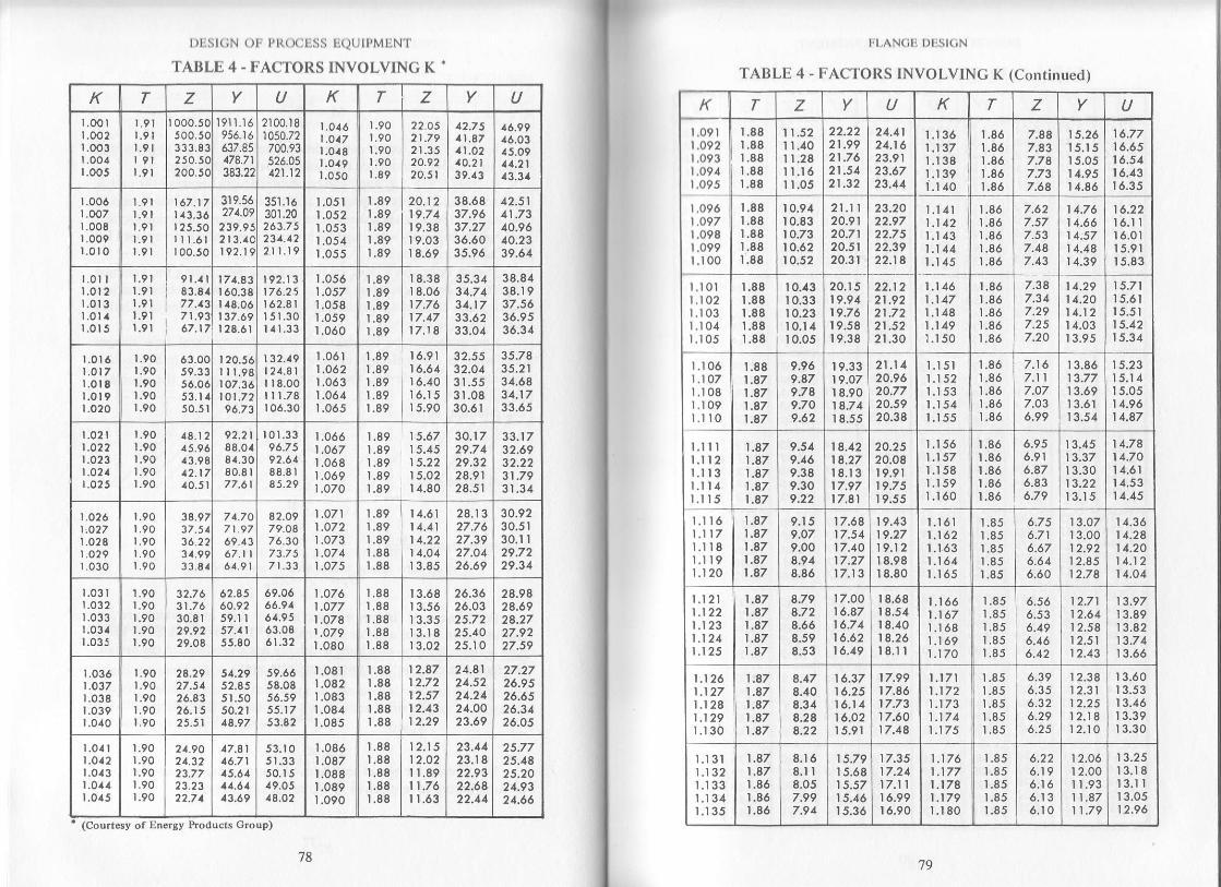
l)l,Sl(;N ( )l l'R( X liSli
TAI]LU 4 - T.'ACTOITS
ll(.!( Jll,MriN l
INVOLVING K "
K T z U K z U
r.oo I|.002l.oo3|.004r.005
r.9l
r.9l| 9lr.9l
r000.50500.50333.83250.50200.50
l91l.t6956.16637.85178.71
383.22
2100.181050.72
700.93526.05a21.12
1.016t.o171.0a8l.or9r.050
r.90t.901.90I.90r.89
12.O521 .7921.3520.92?0.5 |
42.7541.87at.o210-2139.43
46.9946.0345.0911.2143.34
r.0061.OO7r.008r.009r.ot0
9l9l9l9l9l
67.1713.3625.50I t.6l00.50
319.55271.09
239.952 t 3.4Cr 92.1 9
351.16301.20263.75231.122r r.l9
t.051L05 21.053t.0541.055
1.891.891.89t.89t.89
20.1219.7119.38r 9.03r 8.69
38.6837.9637.2736.6035.96
42.514t.7340.9640.2339.64
l.0t Ir.012r.0t 3l.0l ar.015
r.9ll.9l1.9 |r.9lr,91
9t.rl8 3.8177.1371.9 3.67.17
171.A3160.38148.06137.69r28.61
| 92.1317 6.?5t62.81I51.30I { r.33
1.0561.0571.0581.0s91.060
t.891.89t.891.891.89
I8.38I 8.0617.7617.1717.18
35.3 434.7 434.1733.6233.04
3 8.8438.r 937.5636.9536.34
t.0t.0t_01.01.0
t6
t8t9lo
t.901.901.90r.90t.90
63.0059.3356.0653. r,(50.51
II r r.98r 07.36tot.7296.73
20.56 132.19| 24.8l| | 8.00I r 1.78106.30
1.06t1 .062r .0631.064t.065
1.891.891.89L891.89
16.9116.64I6.40l6.t 5r 5.90
3 2.5532.0431.5531.0830.61
35.78
31.6434.1733.65
.021
.o22
.023
.o2a
r.901.901.90r.90|.90
18.t245.964 3.9812.17,(0.5 |
92.2 |88.0t81.3080.8 |
77.61
r0t.3396.7592.6t88.8lI5.29
1.0661 .0671.0681.069|.o70
r.891.891.89r.89r.89
1 5.6715.451 5.22I5.0214.s0
30.1729.7 429.3228.9128.5r
33.1732.6932.2231.7931 .34
|.026t.o271.028LO2 9t.030
t.90t.90r.90t.90t.90
38.973/.5136 223 r.993 3_8,1
7 A.707 t .9769.1367.1|61.9 |
82.0979.O87 6.3073.7571.33
1.0711.0721.073t.o741.O75
t.891.891.891.88r.88
14.6114.41I4.22I4.Ol13.85
28.1327.7627.3927.0426.69
30.9230.5r30.1I
29.34
1.03 |r.0321.03 3r.034r.035
1.90|.90t.90|.90r.90
31.7 630.8 |29.9229,08
62.8560.9?59. r I57.115 5.80
69.0666.9161.9563.086r.32
1.076LO771.o781 .079r.080
t.881.881.88I.881.88
13.68
13.35l3.t 8r 3.02
26.3626.0325.7225.4025.10
2 8.9828.692A.2727.9227.59
r.036t.o37t.0381.039r.0r0
1.901.90t.901.901.90
24.2927.5126.8326.1525.51
51.29
51.5050.2 |48.97
59.6658.0856.5955.1753.82
1.081t.082r.083t.084t.085
1.881.881.881.88r.88
12.87
| 2.4312.29
24.8124.5224.2124.0O23.69
27.2726.9 5
26.3426.05
l-0411.0a2|.0131.0a 4t.0t5
1.90r.90l.9o|.90r.90
21.9021.3223.77
22.71
n7.8116.7115,6111.6A,t 3.69
50.15r9.0514.O2
1.0861 .O87L0881.0891.090
t.881.881.881.881.88
12.15| 2.O2I1.8911 .761 1.63
23.1423.1822.9322.6822.44
25.7725.4825.2024.9324.66
(Courtesy of Energy Products Group)
7879
l l AN( ilr l)l Si( iN
TAULU 4 - I.',\CTOlts INVOLVING K (Continucd)
T Z K T z U
r.oer I|.0e2 llr.093 l
r.oe4 1l
|.oe5 I
tl
r.096 |
| .o97 |
r.0e8 ll
i?33 l
-xI l0lr.102
ll
r.r 03 Ir.r04 ll
r.t 05 ll
---{r.r 06
I
t.r 07 I
t.108r.t 09
I
1.rr0 ]
r.rrr It.ll2
t.n31.114| 'lLl
l r.n6lr. Z
ll. 8
ll.u9tl.l20
1.88I .88t.881.881.88
I 1.5211.401 l.2E1 I.l6I 1.05
21 .9921.7621.5421 .32
21.1124.1623.9123.6723.11
1.1361.137l.t 381.1 391.140
1.86r .861.861.86L86
7.88
7.787.737.6a
15.26r 5.1515.05r 4.951 4.86
16.77I6.6516.5416.4316.35
1.88r.88r.881.88L88
10.91r 0.8310.7310.6210.52
2l.r r
20.9120.7120.5120.3t
23.2022.97
22.3922.14
l.l4l1.142l.l 431.1441.145
1.861.861.86r.86r.86
7.627.577.537.487.43
| 4.76| 4.6614.5714.4814.39
16.22t6.lIr 6.0115.9115.83
1.881.881.881.88r.88
't0.43
10.3310.23l0.l 410.05
20.1519.9419.7 619.5819.38
22.122l .9221 .7221 .5221.30
1.t 46I .1 47'l .l 481.1 491.150
1.86t.861.86r.861.86
7.387.347.297.257.20
1 4.291 4.20| 4.1214.0313.95
15.7115.6115.5l15.42I5.34
1.881 .871 .471 .871 .87
9.969.879.789.709.62
19.3319.07r s.9014.74r 8.55
21.1120.9620.7720.5920.38
l.l 5l1.1521.1531.154l.t 55
1.861.861.861.861.86
7.117.077.O36.99
13.8613.77r 3.6913.61
15.23l5.t 415.0514.9614.47
1 .871 .87| .471.87'| .a7
9.549.469.3 89.309.22
14.1214.2718.1317.9717.81
20.2520.08t 9.9119.7 519.55
1.1561.157l.l 58r.159r.160
r.861.86L86L861.86
6.956.916.876.836.79
13.45
I3.30
I3.t5
14.7814.7014.6114.5314.45
1.871.87t.871 .871 .87
9.1 59.079.008.918.86
t7.6817.5417.40| 7.27t7.13
19.4319.2719.12i 8.9818.80
Ll611.1621.1.63l.t 641.165
t.851.851.85r.85r.85
6.716.676.646.60
13.0713.0012.9212.8512.78
1 4.3614.2414.2014.1214.04
r.t 2l| .122r.1231.124Ll25
1 .a7| .871.871 .871 .57
8.79
8.668.598.53
| 7.OO16.87'| 6.7416.6216.19
I 8.6818.54I 8.4018.26l8.l I
1.1661.1671.1681.t 691.170
1.85
1.851.851.85
6.566.536.496.466.42
12.7112.6412.5812.5112.43
13.97I3.89| 3.a213.7 4r 3.66
1.1261.127t.1281 .129l.t 30
| .a71 .871.871.871 .87
8.178.408.318.2 88.22
| 6.3716.25l6.l 416.0215.91
17.9917.46
17.6017.48
1 .1711.1721.1731 .1741.175
1.851.851.851.851.85
6.396.356.326.296.25
12.3812.31t2.25I2.18t2.t0
13.60r 3.5313.46
I3.30
l l3lt.132t.133t.134t.135
1.87| .87r.86t.uo1.86
8.168.1I
7.997.94
1 5.79I 5.68I J.a/| 5.46I5.36
17.3517.21l7.t Ir 6.99t 6.90
1.176't.1771.1741.1791.180
1.851.851.851.851.85
6.226.196.166.136.10
12.0612.00I 1.9311.8711.79
I3.2513.18l3.l l'13.05
| 2.96
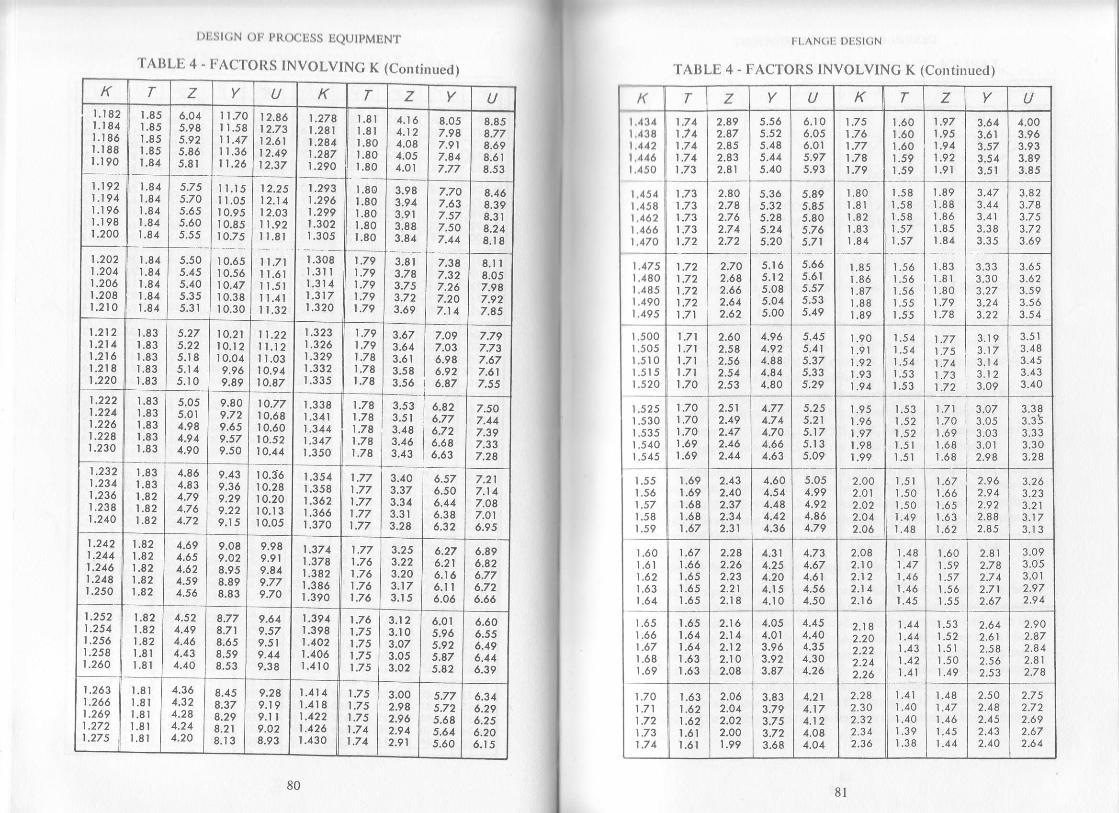
| )l,l.il(;N ( )tr t,t{( X:liSS Ii(ltJ )MtiN I.
'l AllLlj 4 - IJAC'IOtts INVOLVING K (Continued)
K T Z Y U K T z ULt821.1841.1861.188r.t90
1.851.851.85t.851.84
6.045.985.92J.605.8r
| 1.70I 1.58
I1.3611.26
12.8612.7312.61t 2.19| 2.37
1.278I.28t|.2441 .2871.290
r.8lt.8lr.80r.801.80
4.t 64.124.O84.054.01
8.057.987.9 |7.81
8.858.778.698.618.s3
1.1921.194l.t 96l.l 981.200
1.841.841.84t.a41.84
J./ Js.70J.O55.60
I l.l511.0510.9510.8510.7 5
12.2 5t2.t 4I 2.0311.92I l.8l
11 .71I l.6lI l.5lI l.4l11.32
1.2931.2961 .2991.302r.305
1.801.801.80r.801.80
3.983.9 43.9r3.8I3.84
7.70
7.577.507.41
8.468.398.318.248.18
1.2021 .2041.2061.208r.210
1.841.841.841.841.84
5.505.455.40
I 0.65r 0.5610.47t 0.38r 0.30
1.308l.3l I1.3141.3171.320
1.791.79t.791 .791.79
3.8r3.78J./ J
3.69
7.387.327.267.207.1 1
8.1 I8.057.987.927.85
1 .2121 .21 41.2161.2t 81.220
1.83r.83r.83r.83r.83
5.27
5.185.1 45.t0
I0.21l0.r 2I 0.049.969.89
11.22ll.l2I r.03t0.9410.87
t.3231 .3261.329t.332I.JJ5
1 .791 .791.7at.7al.7a
3.673.613.61J.J63.56
7.097.036.986.926.87
7.797.73
7.617.s5
1.222| .2241.226| .22a1 .230
r.83
r.831.83L83
J.UJ5.014.984.944.90
9.809.729.659.579.50
I o.77I 0.6810.6010.5210.44
r.338r.3411.3111.317r.350
| .781.781.781.78|.78
3.533.5 |3.483.463.43
6.A26.776.726.646.63
7.507.417.397.337.28
1 .2321.2341.2361 .2381.240
r.831.831 .82t.a21 .e2
4.864.834.794.7 64.72
9.439.369.299.229.1 5
r 0.3610.2810.2010.13t 0.05
1.3541.3581 .3621.3661.370
1.771.771 .77
t.77
3.40
3.3 4
3.2I
6.576.506.446.386.32
7.2 1
7.t 17.O87.O l
6.9 51.2421.241t.246|.24a1.250
1.821.821 .821.82| .82
4.694.651.624.594.56
9.089.O28.958.898.83
9.989.919.819.779.70
1 .3711.378t.3a21.3861.390
|,/61.761.761.76
3.203.173.15
6.276.216.166.1 |6.06
6.896.826.776.726.66
1.2521.2541.2561.2581.260
1.821 .821.82l.8lL8l
4.524.494.464.434.40
8.778.718.658.598.53
9.649.579.519.419.38
1.3941.3981 .4021.4061.410
1.761.751.751.751.75
3.103.O73.053.O2
6.0r5.965.925.475.82
6.60o.556.496.446.39
1 .2631.266t.2691 .272r.275
l.8lr.81r.8lt.8lr.8l
4.364.324.284.244.20
8.458.378.298.218.t 3
9.289.r 99.i I9.O28.93
1.414L4181.422| .4261.430
t -/51.7 51.75|,/4| .71
3.002.942.962.9 42.91
5.68s.615.60
6.346.296.2 56.206.15
80 8l
l l AN(;li l)lrSl( iN
'fAIJLIj 4 - ITACTOII.S INVOLVING K (Continucd)
t( T Y K T z Y U
|.434L438t.412t.446r.450
t.454t.458t.462t.466t.470
|.475L 480r.485r.490,u7:
t.5001.5051.510r.515r.520
1 .525t.530t.535r.540t_545
t.551.56| .57r.58t.59
r.60t.6l1 .62r.63r .64
r.65I .66| .67t.68
]ot1.701 ,711.72t.731.74
1.741.7 41 .711.74
2.892.A72.852.832.81
5.525.485.445.40
6.106.0s6.0r5.975.93
1.751.761.771.7e1 .79
r.60r.60r .60I .591.59
1.97r.95t.941.92l.9l
3.613.61
4.003.963.933.89
1.731.731.731.731.72
2.802.752.7 62.7 42.72
5.36
5.215.805.765.71
t.80t.8l1.821.831.84
L581.581.581 .571 ,57
r.89r.88r .861.851.84
t.83l.8lt.801.79t.78
3.473.443.413.3 83.3 5
3.823.783.7 53.723.69
1.721.721.721.721 .71
2.702.682,662.642.62
5.1 65.12
5.045.00
5.665.615.57
5.49
r.85r.86| .871.881.89
r.56r.56r.561.551.55
3.3 3
3.273.243.22
3.6 53.623.5 93.5 63.s 4
1 .711 .711 .711 .711.70
2.602.5a2.56
2.s3
4.964.924.884.844.80
5.415.375.335.29
t.90t.9l1.92t.931.94
1,54
| .54r.53r.53
t.77|.751.741.731.72
3.193.173.1 43.123.09
3.513.483.453.433.40
1.701.701.701 .69I .69
2.512.492.472.462.44
4.774.7 44.704.664.63
5.21
5.1 35.09
r.95l 96| .97I .98I.99
t.53i.521 .52r.5lr.5l
1 .711.70t.69t.68I .68
3.07
3.033.Ol2.98
3.3 8
3.3 33.303.2I
1.69r.691.681.68t.6/
2.432.402.372.312.31
4.604.544.484.124.36
5.0s4.994.924,864.79
2.002.012.022.O42.06
t.5t1.501.501.491.48
1 .67t.66I .65L63t.62
2.9 62.9 42.922.882.85
3,26
3.?13.173.t 3
1 .67
t.651.65l -65
2.262.232.212.18
4.314.254.204.154.10
1.734.67
4.561.50
2.O82.102.122.142.16
L481 ,171.461 ,46
1.60r.591 .571.56
2.812.7I2.7 42.712.67
3.093.053.012.972.9 4
r.651.641.641.63t.oJ
2.162.14
2.102.08
4.054.013.963.923.47
4.454.40
4.304.26
2.182.202.222.242.26
1 ,441.441.431 .42t.4t
1 .52l.5lt.501 .49
2.6 42.612.582.562.53
2.902.872.842.8l2.74
1.631 .621 .62t.6ll.6l
2.062.042.022.OO1.99
3.833.793.7 53.723.68
4.211.174.124.084.O4
2.282.302.322.3 42.36
t.4l1.40t.401.39t.3B
1.48
1.461.451.44
2.502.482.452.432.40
2.752.7 22.692.672.6 4

I )list(;N otr pt{(x;tiss IiQtJ ,M[.N't.
'fAllLE 4 - F'ACTOIIS INVOLVING K (Continued)
K T z U K T z U2.382.402.422.442.46
r.381 .37
1.361.35
l 431 .42l.4lr.40t.40
2.3 82.362.3 3
2.29
2.612.592.562.542.52
3.5 03.5 43.583.623.66
t.r0t.o9t.0B1 .071,07
l.t81 .17|,17t.l6t.t6
1 .62l.6lL59t.57
1.78
t./ J1.731 .71
2.4a2.502,532.562.59
L35L34t.331.32r.3l
t.39L381 .37
2.272.2 52.222.192.17
2.502.472.442.412.3I
3.703.7 43.783.823.86
1.06t.05r.05r.041 .03
r .16r.t5l.r5t.l5t.t4
t.)51.531.521.50| .49
1 .701.681 .67
r.64
2.622.6 52.6A2.712.74
r.30r.30r,291 .28L27
1.34r.331.32t.3lL3l
2.1 42.122.O92.O72.04
2.3 52.322.302.272.25
3.903.9 43.9 84.004.05
1.031 .O2t.0lt.0091.002
Lt41.r4t.t3l.t31.1 3
1 .481 .461.45
t.43
1 .621.6 |t.60i.59| .57
2.802.8 32.862.89
1.261.26t.251.24r.23
1.301 .291.28r .281 .27
2.022.O01.98I .961.94
2.202.172.15
4.t 04.154.204.254.30
.996
.989
.982
.968
1.13t.l21.12t.l2t.t I
1.42t.401.39t.38
r.56r.54
l,5i1.50
2.922.952.983.0 23.06
1 .221.22r .21'l .20l.t9
1 .271.26r.251.251.24
1.92r.90r.881.861.83
2.1 1
2.O92.O72.O42.01
4.404.454.5 04.55
.962
.955
.94
.911
.9U
Ll ll.r.t.t0l,t0
r.341.33r.31t.30
1.48
I.461,44L43
3.t 03.t 43.t 83.223.26
l.t 8l.t7l.t6l.t6t.l5
1 .231.231 .22l.2lt.21
1.811.791 .771.751.73
r.991 .971.941.921.90
4.604.654.70
4.8 0
.n8
.nl.911.908.9m
t.t0l.t01.09r.091.09
| .29t.2a1 .271 ,261.25
1 .421.41I.39t.3d
3.303.3 43.3 83.423.46
l t4l.l3l,t2l.t I1.lr
1 .201 ,20l.t9l.l 9l.l8
1 .71r.691 .671.661.61
r.88r.86t.84r.82r.80
4.8 54.904.955.00
.893
.887
.880
.873
1.091.091.081.08
L241.231.221.21
8283
III,ANGI DLSI(iN
l l(;. 9a - TWO PASSARRANGEMENT
FIG,9b, FOUR PASSARRANGEMENT
FlG. 9c - SIx PASSARRANGEMENT
FIG. 9 . MOST COMMON PASS ARRANGEMENTSFOR MULTIPASS CHANNEL
Allowable Flange D€sign Stresses
l hc flange stresses as calculated above shall not exceed the followingvalues:
l. Longitudinal hub stress Sr should not be greater than 1'5 S/" in the
operating condition and 1.5 S/" in the gasket seating condition.
l. Radial flange stress SR shall not exceed S/, in the op€rating conditionand S/. in the gasket seating condition.
I. Tangential flange stress Sr shall not be greater than S/" in the
operating condition and S/, in the gasket seating condition.
4. The greater of 0.5(srf + Sr) or 0.5(Sr, * Sr ) shall not exceed Sr" in the
operating condition and S/" in the gasket seating condition.
If any of the stresses other than S, exceeds the allowable' the flange
I hickness r can be revised till the stresibs are within allowable. However,
if S,, €xceeds the allowable, the increase in flange thickness will not help
and it may be necessary to lengthen the hub, increase the 9r thickness oralter both of them.
Considering Pass Rib Area in Flenge Deign
In certain application of flanges, especially in shell-and-tube heat
cxchangers where multipass channels are specified, the area for pass ribs
also contributes to required bolt load in the operating as well as in the
gasket seating conditions. Its effect may be negligible in some cases but itis advisable to consider it in flange design wherever applicable. The most
commonly used pass arrangements for two, four and six pass channels
are indicated in Fig. 9. In order to simplify the calculations, the rib areas
for each case and for exchanger sizes 6" through 100" inclusive are given
in Table 5. Use ofrib area in llange design is illustrated in the calculation
sheet.
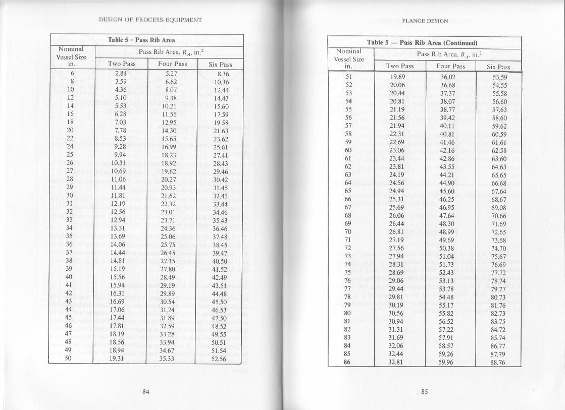
r )lis t(;N ()|l Pl((xiliss riQUIpMl.iN't'
Table 5 - Pass Rib Area
NomlnalVessel Size
Pass Rib Area, Rr, in.2
Two Pass Four Pass Six Pass
6
8
10
12
l116
l8202224252627282930JI
33
3435
36
38
39
4041
4243444546474849
50
2.843.594.365.105.53
6.287.037.788.539.289.94
10.31
10.69
11.0611.44
11.8 t12.19
12.56
12.94
13.31
13.69
14.06
t4.4414.81
15.19
15.56
15.94
16.31
t6.6917.06
17.44
17.81
18.19
18.56
18.9419.31
5.27o.oz8.079.38
10.21
11.56
12.95
14.30
t).o)16.99
18.23
r8.9219.62
20.2720.93
zt .oz22.3223.0r23.71
24.3625.062J. t)26.4s27.1527.8028.4929.r929.8930.543t.2431.8932.5933.28
33.9434.6't35.33
8.3610.36
12.44
t4.4315.60t't.5919.58
21.63
zt.oz25.61
27.41
28.4329.4630.42
3t.4s32.41
33.4434.4635.4336.4637.4838.4539.4'l40.504t.5242.4943.5144.48
45.5046.53
47.5048.52
49.55
50.51
51.5452.56
84 d5
!.LANCE DBSICN
Table 5 - Psss Rib Area (Continued)N omlna
Vessel Sizein.
Pass Rib Area. Rr, in.2
Two Pass Four Pass Six Pass
51
52
53
5455
56575859
606l6263
646566676869707l72
7475
76
77'18'79
8081
8283
8485
86
19.69
20.0620.4420.81
21.t921.5621.9422.31
22.6923.0623.4423.81
24.1924.5624.9425.31
25.6926.0626.4426.81
27.1927.5627.9428.31
28.6929.0629.4429.81
30.1930.5630.9431.31
31.69
32.0632.4432.81
36.0236.685t-3t38.0738.7739.4240.11
40.81
4t.4642.1642.8643.5544.2144.9045.6046.2s46.95
47.6448.3048.9949.69
50.3851.0451.73
52.4353.13
53.7854.48
55.17
55.8256.s257.22
57.9r5 8.5759.26
59.96
53.5954.5555.58
56.6057.63
58.6059.62
60.5961.61
62.5863.6064.63
65.6566.686'1.64
68.6769.08'70.66
71.6972.65
73.68'74.'10
7 5.6'l76.6977.72'78.'74
'19.7'l
80.7381.7682.73
83.7584.'72
85.7486.77
87.7988.76

l)list(;N Olr Pt{( x:Ess EQUTPMENT
Tsble 5 - Pass Rlb Arer (Conrinued)
NomlnalVessel Size
in.
Pass Rib Area. Rr, in.2
Two Pass Four Pass Six PassEt88
89
909l9293
9495
96979899
100
33,l933.5633.9434.31
34.6935.0635.4435.81
36.t936.5636.9437.31
37.6938.06
0u.6561.3562.W62.'7063.3564.0564.7465.4466.0966.79
67.4968.1868.8469.53
E9.7E
90.81
91.8392.8093.8394.8595.8296.8497.8798.8399.86
100.82101.85
102.87
EXAMPLE NO. 1
Design a pair of welding neck flanges to be used to contain atubesheet ofa TEMA BKU type of exchanger. The 4l in. I.D. two passchannel designed for 150 psi at 500.F is built ofI in. thick A_515_70 piateinclusive offin. corrosion allowance. Theshell sideflangeis to be weldedto a 41 in. I.D. x 75 in. LD. cone designed for 460 psi at 650.F. The coneconsists of l; in. thick 4_515_20 plate inclusive of$ in. corrosionallowance. Assume ironjacketed asbestos filted gasket on'Uotf,.iO", unOuse A-105 flanges with A-193-87 Bolts_
86
and
87
F'LANC!: DESIGN
SOLUTION
ln this case we will have two flanges bolted together but designed fordiffcrent conditions. The required bolt load in the operating conditionlbr the shell side will govern the design of both flanges because of lhehigher design pressure. Since the gaskets on both sides are of the samenraterial, the required bolt load for gasket seating will be greater for thelow pressure flange. Since such a high design pressure is involved, gasketscating probably will not control the design. Tberefore, the shell side
llange will be the independent flange while the channel side will be thedcpendent flange.
Independent flange has to be designed first so that we can carry overthe bolt load for the design ofthe dependent flange. Both the flanges willbc designed here in detail, but the attached calculation sheets can be used
to save time. Both these flanges will be designed using corrodeddimensions because the corroded condition results in greater thicknels.
Design of Independent Flange
Refer to Figure and design steps on Weld Neck Independent FlangeDesign Calculation Sheet. Now we have,
p:460 psi
Sa:25,000 Psi
S":25,000 PsiSr' : 17'500 Psi
Sr": 17,500 Psi
Also in uncorroded condition
Assume
B :41 in'go:t^:l'25ln'
9 t: 1.25(s o\: 1.25(1.251:1.5625 in.
Thus in corroded condition
B'41.25 in.
9o:1.125 in.
g r:1.4375 in.

DESIGN OF PROCESS EQUIPMENT
Now
,t = 1.s(gJ- 1.5(1.125)= 1.6875 in. (minimum)
stope =!9r:sd: $431s--!r25) -0.1852 < 0.333' h 1.6875
Therefore, the flange can be designed as an integral type as shown inFig. la- Now assune (48) 1| in. dia. bolts. From Table 3, for lf in. dia.
FLANOB DESION
n =f,tu.t sF +oo = 7 23,4s2.t tb
W : 123,492.1 + t2t 255.7 : 844,747.8 lb
.4.:Greareror'## * t*,ltl't=rr.tri".'
From Table 3, the root area ofa l| in. dia. bolt having 8 threads per inchis 0.728 in.2 which gives
A t : 48 (0'7 28l, : 34'9 44 in'2
Since 74, > .4., therefore (48)lI in. dia. bolts are adequate. Now
W:0.5(33.79 + 349,14)25,000 : 859,1 75 lb
r^,,:ffi,=0.4088in.Since N > N,ir", therefore chosen gasket width is adequate.
Flange Moments Calculatiom
H D:;@l.2512 460 =614,745.9 lb
Hc:HP-121,255.7 lbH r:723A92.1 - 614,745.9 = 1O8,746.21b
h D: 1.5 + 0.5(1.437 5) = 2.21 88 in.
he :0.5(47.r25 -44.75): 1.1375 in.
fir:0.5(1.5 + 1.4375 + 1.1875) =2.0625 in'
Now
M o= 6t4,7 45.9(2.21 88) : 1,363998 in- lb
M e =121,255.7 (!.1875)= 143991 in-lbM r = 1O8,7 46.2 (2.06251 : 224 289 in-lb
Therefore,
bolts. we have
R : 1.5 in.
E = 1.125 in.Now
c : B + 2(s ) + 2(R) : 41.25 + 2(r.437 5) + 2(r.5) : 47 .125 io.and
A - C + 2(E) : 47.12s + 2(t.t25l : 49.37 s in.
Gaslet and Bolting C,alculatiom
From Table 1, for an iron jacketed asbestos lilled gasket
and
m:5- I)
v=76WAssume
N :0.5 r!.Fig. la. of Table 2.applies to our situation. So,
u.:!=!=o.zsn;
D:0.25 in.Now
G:C - a-2(0.375)-2(Q:a7.p5 - 1.rzs -2(0.375) -2(o.2s):44.75 in.
Therefore
W^z* :0.25(n)44.7 5(7600) = 267,1t4 lbH, : 2(n) 0.2s (44.7 5X3.7 5) 460 : r2r,25 s.7 tb
and
Therefore
' See note on page 58
88
Mo= 1,363,998+ 1 43991 +224,289 :1,732,278 in-lb
t)list(;N ()lr pt{(xjriss ltQUlpMIiNT
Now, for lhe gaskct seating condition
Therefore
H e : W:859,175 lb
Mo : 859,175(1.187s) : 1,020,270 in-lb
Actual borr spacing - r(l)
= r{4J-125t
:3.0843 in.-n48
and
Assume t:2.75 in.
Maximum bolt spacing:2(t.l 251 , -6975L-:6.Ij2J in.{J. /) +U.)l
Normal bolt spacin E:2(l.t25l +2.j5:5 in.Since, Actual bolt spacing<maximum bolt spacing, the chosen boltspacing is O.K. and also actual bolt spacing <normal bolt spacing, thecorrection factor Cr: 1.0.Thus, the calculation factors are
M:u21J(1):a1,se5
M:l'020'270(l)-1471441.25
NOTE*The value of r|/., should be taken from the low pressure dependent flange ifit results Ingreater value there because ofrib area or dilTerent gasket miterial. ln tf,i. c"se
"in""ir,"operadng condilion is controlling the gasket seating is of insignificant value_ However,wnen rwo matrng tianges are designed to hold a tubesh€€t between them with the sam€pressurf oneachside ol the tub€sheet lhe llangeresullingin a grealer value of l,y-) due ronD area or gasket materjal should be considered as the independenl flange and lhe otheras the dependent flange.
Deaermining Shape Constants
.. 49.375K: _ * : t.19741.2s
From Table 4, for K: l.l9?
T: 1.84
z:5.625y:10.9
90
|tnd
Now
From Fig. 4, for
we have
ITLANCI DDSICN
U : ll9'75
gr :1 4375 = t.2l'Ie
9o |.125
ho: Jqtzs(trzr:o.stzzft 1.687s ^..-.ho 6.8122
sJ = t.zllg
9o
Similarly from Fig. 5
and from Fig. 8
Now
and !:0.2477no
F:0.894
V:O.441
I:1.0
0 894
':-:u',,"and
rto75d :' ffi to'trzzltt' t2512 : 234 1 | 5 |
Cslculating Other Stress Frctors
a:2.75(0.1312) + 1 : 1.3608
a :$)z: s to.ttrz) + I : r.48 I 1
,:{ff:ozrro
a:ffi:o.ostat :0.7396 +0.0888 =0.8284
91
I )list(;N ()tr pRO(jtjss tjQtJtpMIjNT
Calculating Stresses
Operating Condition
^ I (41.995)t": O.S.Zao1,.43 75lz:24.532
psi <26.250 psi O.K.
1.481 I {41.995).s^ : -----: '
= 9.928 psi < I 7.500 psi O.K." o.8284t2.75r
s,:4tp-e:!192 - s.62s (e.e28) :4.683 psi < r 7,500 psi o.K.12.7 5)2
Since S^ > Sr, therefore, 0.5124,532 + 9,928): I 7,230 psi < I 7,500 psio.K.
Gasket Seating Condition
^ | (24,7 34)s' :9 ffi.+:ts rz=
14'449 psi < 26'250 psi o K
^ t.481| 124,7 341s": O.tZt+tZrSl
:5.848 psi< 17.500 psi O.K.
24.1 34t 10.9 |Jr - ,.-*,, -5.625(5.848):2,755 psi<17.500psi O.K.
v. t)rSince
S^ > Sr,therefore,
0.5(14,449 + 5,848): 10,149 psi < 17,500 psi O.K.
All stresses in both the operating as well as the gasket seatlngcondition are within allowables. Thus, the independent flange design iso.K.
Next we will discuss the design oftbe channel side or the dependenlflange.
Design of Dependent Flange
Refer to Figure and design steps on weld neck dependenl flange designcalculation sheet. Here we have
p: 150 psi
Since, the flange and bolt materials are the same as for the
92 93
lll-AN()lt l)tisl(iN
rldcpcndent flange, the values of Sr, S', S7,, and 57, remain unchanged'
Now, in the uncorroded condition9o: t,:0 5 in'
Assume
s' : 1.31 5(g'\ : 1.375(0.5) :0'687s in'
lhus, in the corroded conditiongo:O 375 in'
lrrrd
9 t:0 5625 in'
Assume
fi:1.5 in. > 1.5(so)>0 5625 in O'K'
Slope:(0.s625 - 0.37s) :0.125 < 0.333
l.)
Therefore, the flange can be designed as an integral flange as shown
in Fig. la.Since, both the flanges are to be bolted together, the number and
sizc of bolts, and diameters B, C, G and .4 will be the same as for the
independent flange. Also, the values of m and y will remain unchanged
since the gasket material is the same.
The value of radial clearance R will be greater than the minimumrcquired for this flange, because its bolt circle dia. C has to match the boltcircle dia. of the independent flange and its g1 is smaller than ,r of the
independent flange. So in this case
c-tB+2(q,)l 47.125- 141.25'r 2(0.5625)l ".". -p- -- 1:: :::' ','z2We must also include the effect of rib area R,r, since the channel has
lwo passes.
From Table 5,Ior a two pass 4l in. nominal size shell, R, : 15.94 in'2
(;asket and Bolting Calculations
fhe width and the effective width of th€ gasket will be same as for the
independent flang€. Noww^, : 10.25(n144.15 + 0.s(1 5.94)1 7600 : 32't,686 tb
H,: l2(nl1.2s(44.75) + 1 5.9413.75(150) :48'506 lb
H :X(4.7 s)' | 50 : 23 5,s21.3 tb

DESIGN OF PROCESS EQUIPMENT
W^tr =844'747'8lb
which will result in the same ,,{n as earlier, thus llzwill be the same also.
Flenge Moments Calculatiots
Now
H D = ;(r.2sl2 t so: 200,460.6 rb
Hc:w - H =844,74'1.8 -235,921.3:608,826.5 lbH r:235,921.3 -200 460.6:35,460.7 lb
lro:2.375 + 0.5(0.5625) =2.6563 in.
ha:0.5(47.125 -44.75)= 1.1875 in.
Irr:0.5(2.375 + 0.5 625 + 1.1875\:2.0625 in.
M o= 2A0160.6(2.6563) : 532,484 in- lbMc : 608,826.5(1.1 87 5) : 722,982 rn- lb
M r:35A60.7 (2.0625):23,133 ;n- tO
Therefore.
M o:532A84 + 722'982 +73'138 = r,328,604 in- lb
Now, for the gasket seating condition
Therefore,
Assurne
t :43125 in.
Normal bolt spacing will be greater than the actual bolt spacing,thus Cr = 1.0.
Thus, the calculation factors are
Hc=W=859,1'15lb
Mo : 859,175(1.1875): 1,02O270 in-lb
and
rThe valuc of lvnl is taken from high pressu.e independent flange.
94
u:t'3?Y0):tz.zov
u:t'v!oi?#(t) :z+,tz+
FLANOB DESIGN
Determining ShaPe Conslants
Since the value ofK is the same as in the independent flange the values ofT, Z, Y and U will remain unchanged.Now
gt -05625 ' -
go 0.375:l)''^.ho : \t 4t .25 (0.3'15) : 3 .933
ft 1.5_ _ _i_:0.3814fto 3.933
From Fig. 4 for grlgo = 1.5 and ft/io =0.3814, we have
F:0.867
Similarly from Fig. 5
V:0.343
and from Fig. 8
f=t.0Now
0.867 - ---.e:i5i=0.2204
ano
a : ffi o.rlltto.37sF : le.3oe4
Calculating Other Stress Fsctors
1. : 4.3125 0.22041 + l : 1.9505
n : Q)+.t
r zs to.zzo4t + | : 2.267 3
,={ff=-r.ooo'
a:ffi=r.rsrsi:1.0601 +4.1535 = 5.2136
95

l)l1Sl(;N ( )lr l,t{( X;tiSS ti(ltJtpMltN t.
Calculating Slrcsscs
Operating Condition
( I r12.209\.. _-" 5.2 | 36(0.5625,1
2.267 3t32.2091\^: - -753 psi <17.500psi O.K." 5.2 t36(4.3 t25),
J2.209 t10.91s'= t.l:l:st' -5625{753): 14.642 psi < l7.500 psi o K.
Since
St>S^,ther€fore,
0.5119,525 + 14,642): I 7,084 psi < 17,500 psi O.K.
Gasket Seating Condition
- 1\24,134)5n:5.2tlo,'Jo2s
rz= |4,994 psi <26.250 psi O K
^ 2.26'7 3 (24,'134)s"-S.:r:oajl25,r:578 psi< 17.500 psi O.K
)4114t1n51{- : --'-- " " -' - s K)sr{'78} : I 1,245 psi < | 7.500 psi O.K.
t4.3t 25t,
Since
St > S^,
therefore,
0.5(14,994+ 11,245): 13,120 psi < 17,500 psi O.K.
All the stresses in both the operating as well as the gasket seatingcondition are within allowables, thus the dependent flange design is O.K.
Additionaldesired thickness for raised face, counterbore, tongue orgroove should be added to the calculated thickness r to obtain the finaltotal thickness ofthe flange. ln the above example we added rt in. to thethickness ofeach flange for counterbore. The toral final thicknesses andthe arrangement ofuse ofabove designed flanges is shown in the Fig. 10.
96 97
trt.AN(;li Drisl(;N
TUBESHEET
Fis. l0 - EXAMPLE FLANGES
EXAMPLE NO.2
Design a ring flange to be used on a 60 in. O.D., A-240-TP304Lr ylinder designed for 140 psi at 425"F. The cylinder is I in. thick and no,rrlrosion allowance is allowed. Assume TP-304jacketed asbestos filled|ilsket and use an A-105 flange with A-193-87 bolts. Allow *3 in. for, otrnterbore and I in. for TP-304L overlay.
SOLUTION
llclcr to Figure and design steps on ring flange design calculation sheet.Now ys 13y9,
p: 140 psi
Sr:25,000 Psi
S":25,000 Psi
sr,: 17,500 psi
Sr' : l7'500 Psi
Allowing I in. clearance between the O.D. of the shell and the I.D. of1l)c ring flange we get
B:60 + 0.125:60.125 in.
(:IJANN E Li;IDE(:Y L INDER

t.DESICN OF PROCESS EQUIPMENT
Assume (56) $ in. dia. bolts. FromTable 3, for ]in.dia. bolts,we havc
R:1.25 in.
E = 0.9375 in.
Allowing for I in. weld all around for securing the flange to thocylinder, we get
C = B * 2(weld size)+ 2(R):60.125 + 2(0.51+ 2(t.25):63.625 tn.
and
A: C +2(E) = 63.625 +2(0937 5):65.5 in.
From Table 1, for stainless steel jacketed asbestos filled gasket, we
have
n:3'75y = 9000
Assume N:0.5 in.
Fig. (1a)ofTable 2 applies to this situation, so,
therefore,
r":f:f :o.zsiu
b:0.25 in.
Now
G = C - a - 2(O.25) - 2(b)= 63.625 -9.875 - 0.5 - 2(0.25):61.75 in.
W^z : 0.25(n\6r.'t 5(9000) : 436,485 lb
H r = 2(n)0.25(61.7 5)3.75(140):50,923.3 lb
n =!(j.l sl, t +o :4 1 9,268. 1 lb
wa:419,268.t + 50,923.3 :470,191.4 lb
thus
" 436,485 470,t91.4 ,6 -^-- :, u/,=Creater ol 2S,OOO
or 25p66
:lr.rurr 1n.-
From Table 3, the root area of a { in. dia. bolt is 0.419 in.2, whichgives
A t : 56 (0'419) : 23'464 in''z
9899
FLANOE DBSION
Since ,4, > .4., therefore (56) $ in. dia. bolts are adequate. Now
tv:0.5(18.8077+23.464)25,000:528,396.3 lb
0nd
N-": 1.1-6=a=(-2ry :o.168oin.' ''" 2(z)9000(61.75)
Since N > N,nin, therefore the chosen gasket width is adequate.
FlNnge Moments Crlculatiors
H ^:n (60.125l'l4o:3g'7,4g1.'t lb
HG: H P=50'923'3 lbHr:4t9,268.t -397 '491.7 =21'776.4 tb
. 63.625 -60.125 . -- .ll'=
-:
t'ts tn'
fto:9.5163.Urt - U 1.75):0.9375 in.
ir:0.5( 1.75 + 0.9375) = 1.3438 in.
Now
M o:397,491.7 (r.7 5):695'610.5 in' lbMo : 5Q923.3(0.93751 = 47,7 40.6 in' lb
M r:21,77 6.4(1.3438): Z9'263.t tn-tO
Therefore,
M o:695,610.5 + 47,74O.6 + 29,263.1 :772,614 2 in- lb
Now, for the gasket seating condition
Therefore,
Now,
H "=
W= 529,396.3 16
Mo: 528,396.3(0.9375) = 495'371'5 in-lb
, :77]^6r?12 : t2,850. r 322
r=ffi:r.oar

I)tsSI(;N oII PR(XJESS EQUIPMENT
From Table 4, for K : 1.089
Y:22.68
thus
:4.0809, say 4i in.17,500
lrtA1 6? 5lBolt sPacing: "\"' *-1:3
5694 in'
2a + t :2(0.8'7 5\ + 4. 125 : 5.875 in.
Bolt spacing<(24+r). Therefore, Cp :1.Q. The moment factorstays the same and the thickness calculated above is adequate.
Adding ]j in. for counterbore and ; in. for stainless steel overlay' we
have the total minimum thickness of the flange as
t:4 !25 + 0.18'15 +0 125 :4 43'15 tn'
therefore, use 41f in. total thick flange.
Calculating Maximum AllowablePressures for Flanges
Maximum allowable working pressures are required either fordetermining unit test pressure or for code stamping purposes. When the
body flanges are designed by computer, MAWP, (maximum allowableworking pressure hot and corroded) as well as MAB (maximum
allowable pressure new and cold) are generally given in addition toflange and hub dimensions. These pressures if required, can be easily
determined when the {lange is designed manually, or an existing flange is
to be evaluated. Since, MAP is very rarely desired only the technique fordetermining MAWP will be discussed. However, the same technique can
be repeated to determine MAP by using uncorroded flange dimensions
and allowable stresses at atmospheric temperature.
Calculating MAWP for Weld Neck Flange
Refer to Figure and calculation steps on the calculation sheet. For a
newly designed flange all the shape constants and other stress
calculation factors can be taken directly from the design calculations.
However, while evaluating an existing flange which does not have any
design calculations available, the applicabl€ shape constants and other
stress calculations factors may have to be determined
12,850.r322(22.68)
100l0l
For K
FLANCE DESICN
For K: AlB, nnd out the values of constants T, Z' Y and U ftom'litblc 4.
C culate ha, g r lgoand ft/hq and from Fig. 4, determine the value of
constant F corresponding to the calculated values of 9t/ go and hlhs'
Similarly, lind the values of tzand/from Fig. 5 and 8 respectively'
Now calculate e and d. Also using the thickness of the flange t
cxclusive of any counterbore, overlay, raised face, tongue or groove'
calculate stress factors a, p, 1, 6 and ,i.
If bolt spacing exceeds (24 + t), calculate correction factor
- /Bolt sPacingtt:t/ 1zc+rr
Otherwise, assume Cr: l. Also, if the flange is not designed for any
nrultipass cylinder, the rib area, Rr, can be assumed equal to zero'
Now, calculate the lever arms ho, ho and fir for integral type flange
lnd determine the MAWP as follows:
M:
,, I 5.S"lvlnax= :::_:+! (4)II
^8r-
and M^"*=
AaSu
;G2 +l2nbc'n + R
^(m))
:n16+tF-2B1t;z
P (1)
(2)
(3)
(6)
(7)
(8)
M
= lr^ (5)9D,f
therefore Mo:
thus MArWP: Smaller of (1) or (8)
Calculating MAWP for Ring Flange
Refer to Figure and calculation st€ps on the calculation sheet'
: .4/8. find out the value of shape constant yfrom Table 4'
2S s"
ls-allqlr4le "!€I!!Pls!l!I4CF
!p' - a' 11t ,.4

r)Est(;N oF PROCESS EQUIPMENT
If bolt spacing exceeds (24 + l), calculate correction factor
Otherwise, assume Cr:1. AIso, if the flange is not to be used in amultipass cylinder, the rib area, Rr, can be assumed equzl to zero.
Now, calculate the lever arms io, in and fir for ring type flange anddetermine MAWP as follows:
PAoS u
therefore,
f,G'z+l2rcbGm+ Rn@ll
,^^":+
,":ryMo
(l)
(2t
(3)
(4)
thus MAWP: smaller of (l) or (4)
EXAMPLE NO.3
Calculate MAWP for the weld neck indep€ndent flange designed inexample l.
SOLUTION
In this case, since the flange design calculations are available, theshape constants and stress calculation factors are already known. Wehave
^ ' (nt')r,*r2nbGm+ Rn(m)lho*frrc, - ntfn,
T: t.84
Z:5.625Y= 10.9
U:1r.975
r02
also
IILANCE DESICN
F:0.894V:0.441
e:O.l3l2d:234.r15rr: 1.3608
f = 1.481 I
l:0.7396d:0.0888,;" =0.8284
Cr:lR,n:0Sr:25,000 Psi
Sr, : 17,500 Psi
B:41.25 in.
I t:1.4375 irt.G =44.75 in.
m:3.'75 in.
b:0.25 in.
At:34.94in'2ho:22188 in'ftc:1.1875 in.
hr:2.O625 in
t:2.75 in.
and
Now
p 34.94(25,000)
f,{ul sF + 7z1"yo.2s (44.7 s)3.i 5 + 0)
:475.6568 psi -475 psi
103
(1)
I 10.9 5.625(1.481l)ol.zg4rl.a3zit,
* tzlsy,- g.8zuo 1\',
:50,312.4596 in-lb
2(17,500)
+-t --0.8284(I.4375t' 0.8284(2.75)'
1.s(17.500)
n.8ru1!1-.-7sf = ul4'e35 in-lb
, ,=,r t1:t=9
- = ,. : 74.021 i^-tbt-481u.8284(2.75)z
;: 17j5,9-,, ,=,,, = 156.984 in-lbr0.9 _ 5.62s(r.481r)(2.7s)2 .8284(2.712
74 o -42'652 0419(41'25) : t,759.396.7i
I-41.25, 12.062s :467.20t2 psi - 467 psiI
thus MAWP:467 psi
EXAMPLE NO.4
Calculate MAWP for the ring flange designed in example 2.
S.r,: 17,500 Psi
B:60.125 in.
DESI(;N OF PROCESS EQUIPMENT
2(17,500)
t.481 I:42,652.0419 in-lb
(2)
(3)
also
therefor€,
(4)
(5)
(6)
a)
(8)
SOLUTION
ln this case we have
Y=22.68 Re:0Cr=l 56:25,000 psi
| ,7 59 ,396.'7 3
f,{u.zs)' z.xat + l2(n)0.2s(44.7 s)3.7 s + olt.t v s +Eg4.j s,
tQ4 105
(i:61.75 in.
m= 3.75
h:0.25
F'LANOE DESI(iN
Ar:23.464 in.'1
hr= 1.75 in.
t :4.125 in.
13129.3403(60.125)
fiu:9.9375 'n./rr:1.3438 in.
rr rttl
therefore,
23.464(2s,000) : 174.6607 psi
tt6l.75), + l2(z)0.25(61.75)3.?5 + 0l4-
(4.t25\'z r'7 ,s00
- 174 psi
:13129.3403 in-lb22.68
(l)
(2\
Mo :789,401.5855
!f,O.tZSl' t.t S + lzn(0.25)61.7s(3.75) + 010.9375 + f,@.ts'
(4)-60.r2s'?).l1.3438 : t42.4ss psi - I42 psiI
thus MAWP : 142 psi
789,40 r.5855

l)tist(;N ol, PR()cEss EQUIPMEN'I'
FLANGE DESIGN WITH FULL FACE GASKETS
The ASME Boiler and Pressure Vessel Code does not coverthe rulesfor designing flanges having the gasket beyond the bott holes. This sectiondiscusses a method of designing such flanges as recommended by TaylorForge and Pipe Works3. This method follows the framework and theterminology of the code rules and provides for simplicity of calculations.
It is assumed that full fixation at the bolt circle is produced duringbolting up prior to the application of the internal pressure. The inner edgeofthe flange in this condition is assumed unrestrained so that the reactionof the outer gasket is determined from static equilibrium about the boltcircle.
Design of flanges with full face gaskets is canied out using theASME Section VIII Division 1 Rules for Bolted connections using narrowface gaskets with the following modifications:
The gasket contact area shall be divided into two parts by the boltcircle. The inner gasket reaction shall be determined as the larger of llo orIlo in accordance n'ith the Code and the outer gasket reaction shall betaken as the larger of flo, or llpr which are given by
Ha:Ha 1 la 1 and Ho,=H, 1 la 1\ h"' ) \h", )
Where ft6 and ftc1 represent the moment arms of the resultantgasket reactions with respect to the bolt circle.
Assuming uniform gasket pressure distributed over annular sur-faces, these distances may be expressed as:
hG= (C-B) (28+c) and hc1= 6-C) (2A+ c)6(B+C) 6(C+A)
The minirnum required bolt load then is obtained as the greater ofthe folloY/ing two values:
W^t=H + Hp+He1=H+ H, ( 1, 9\\ nct Iand
W^z= Ho* Hat- Ha t | + !-q t,-( ho,)
The botting requirement can be checked using the applicable boltload calculated above. The flange can now be designed like other flanges
106 107
IILANCB DDSICN
wilh thc cxception that th€ sum of the inside and outside gasket moments
cclual zero, and accordingly the total applied moment becomes:
M"= M 1t). M7
In addition, for flange design with narrow face gasket, the momentrcmains ofthe same sign throughout, while in the case ofa full face gasket
ir moment reversal occurs. The moment due to gasket reaction is given by
Mc= Hehc: w-Hr1.1-lLh" ho'J
Since the gasket moment M6 may be greater than the resultantrupplied moment M,, the following additional check of the radial bendingstress at the bolt centerline will be required:
.s^.:6Mc"r'C
The ring effect and the reduction in section caused by the bolt holes
have been neglected inthe above formula. However, the given value of the$tress is quite conservative, since the moment at this location may be
cxpected to be lower than calculated.
EXAMPLE NO.5Evaluate the design of standard 24 inches Taylor Forge Class 125LW
(Light Weight) flange as shovr'n on page 101 of Thylor Forge catalog 571foruse with full face 75A Durometer Elastomer gasket. Design conditionscan be assumed to be 75 psi design pressure at 300'F Use sA-181 class 60
flange material with SA-307-B bolting. There is no corrosion allowanceand assume g, equal to gr in evaluation.
SOLUTIONThe dimensions of the flange as obtained from Taylor Forge catalog
571 are shown in the sketch on the calculation form for flange design withfull face gaskets. Refer to this form for calculations of flange evaluation.(see page 132 )
The calculations show that 1 inch thickness of the standard flange is
not adequate for the desired design conditions of 75 psig at 300'F as thecalculated tangential stress in the flange, Sn is greater than the allowable.Thus, the thickness ofthe flange must be increased to 1.125 inches in orderto bdns all the stresses within allowables.

l,l.Sl(,N ()l l,lt(n li\\ l.(llltl,MljNI
Nomenclature
c Diameter of bolts, in.
,4 Outside diameter of flange, in.
.4, Actual total cross-sectional area of bolts, in.2
.4. Total required cross-sectional area of bolts, in.2
b Effective gasket seating width. in.
bo Basic gasket seating width, in.
B Inside diameter offlange, in.
C Bolt circle diameter, in.
C F Moment correction factor
e Faclor f/fto for integral type flanges and F "lho
for loose typeflanges
E
fF
FL
9o
gr
G
h
Radial distance from bolt circle to outside of flange, in.
Hub stress correction factor
Factor for integral type flanges
Factor for loose type flanges
Thickness of hub at small end, in.
Thickness of hub at back of flange. in.
Diameter at location of gasket load reaction, in.
Hub length, in.
fi, Radial distance from bolt circle to circle on which llo acts, in.
hc Radial distance from gasket load reaction to the bolt circle : (C
- G\l2,tn./167 Radial distance from outer gasket load reaction to the bolt
circle. in.fio Factor JBgo, in.
hr Radial distance from bolt circle to circle on which F1?. acts, in.
H Total hydrostatic end force, lbH D Hydrostatic end force on area inside of flange, lbHa Gasket load: W^t - H ,lbilc, Outer gasket load, lbHp Total joint-contact surface compression load, lbHpt 'lolal outer joint - contact sudace cornpression load, lb
108 109
l'l AN(;11 l)lrSI(;N
It, l)illclcncc hctwccn total hydrostatic cnd lbrce and the
hydrostatic cnd lorcc on area insidc of flange : H Hr, lb
K Ratio of outside to inside diameter of flange: ,{/B,n Gasket factor
M Calculation factor for operating condition: M oC t l B
M Cafculation factor for gasket seatrng= l14ogo1U
MD Component of moment due to HD, in- lb
Md Component of moment due to Ho, in- lb
Mo Total moment acting upon the flange for the operatingcondition, in-lb
Mo Total moment acting upon the flange for the gasket seating, in-lb
Mr. Component of moment due to Hr, in- lb
n Number of bolts
N Gasket width, in.
P Design pressure, psi
R Radial distance from bolt circle to point of intersection of hub
and back of flange, in.
R,r Rib area, in.2
S. Allowable bolt stress at atmospheric temperature, psl
S, Allowable bolt str€ss at design temp€rature, psr.
57, Allowable stress for flange material at almospherictemperalule, psl.
Sy, Allowable stress for flange material at operating temperature'psr
c
s
S^tsr
ttr
U
V
VL
W
W,
Calculated longitudinal stress in hub, psi.
Calculated radial slress in flange. psi.
Radial bending stress at the bolt centerline, psi
Calculated tangential stress in flange, psiFlange thickness, in.Vessel or nozzle wall thickness, in.
Factor involving KFactor involving KFactor for integral type flanges
Factor for loose type flanges
Flange design bolt load for the operating condition or gasketseating, as may apply, lb
Required bolt load for operating condition, lb

DESI(;N OF PROCESS EQUIPMENT
W, Minimum required bolt load for gasket seating, lb
y Gasket or joint-contact-sudace unit seating load, psi.
Y Factor involving KZ Factor involving K
REFERENCESASME Boiler and hessure Vessel Code, Section VIII, "Pressure Ves-
sels," Division 1, ASME, New York, N.Y., 1983.
"Moclem Flange Design, " G&W Taylor Bonney Division, Bulletin No.502, Seventh Edition.
Design of Flanges for Full Face Gaskets, Bulletin No. 45, Thylor Foryeand Pipe \!brks, Chicago, Ill.
3-
t.
ll0lll
DESIGN FORMS

t,a,xE
i,I\HJ
].Ita
t)
t,a\tvlrr Iil,
rl
,lr)4,
It.
,ut*.|rl1
X
F
z
an
ut{zaz4qr5-z
F]
rttzF.s3()
z
zFq.tV
tl
q,d
a
tl
+
\ls
+tl
+
:t
9b9669Ebo,9t4
:s
v)
s
\ll
U)
+\
s
zF&lI]
2tr.iS
gl
F
p
zFi
TA
lit{Vaa
)FIq
14
I4Fu)
tl
II
taI
tl
tl
.E
tl
tl
tl
+
+
tl
ztllu)
vv2
Fz
rl'l
z>J
\U
v,
a9.Eg
v,N
I
S:
t-t4
4a
:s
=r;'
9ooo?P <r,
F-
tl
'E9
tl
t4
!o.A-=:
N
tlF
:-
t-lt,+
+v,
.1
vt
93-:a
tl
+
{tl
tl
al
Itl
U
9r9$.: i:58n 9i
II
U
t1
)l>
I
ll
zF
11
w
Y
zI+
II
+tl

azFttl
Fvaa
;FF.l
3C)U)v,s.l
F
ozF
;t'{I(J
()CA
EI
t-
F
+
tl
z
Ft4vU)
Fz
z.t<
z
rt)V
ZAz6tlt,t
z
tlF.
v)z?s3uzFr
zFrqJvv,
tl
..-
I
a(
ll
rl
s
s
irl
>9lt\
so
=II
\
v)
+
s
R
tl'i
z
NI
sT
F
v2
gobo?2,'.,t--
tl
s6
S
!ovr=
=!
NI +
o
v\+
n
'43
Ibol
':i |^
(rlq- t..l
a(J
tf:iai:;13 i;53=oE
{+
tl
Itl
I
ll
)l>II
7FtqaaFIl]v
3
zI
a
-itl
=-
I
tl
+
tlU
+
tl
+tl
v
F
Ta;7,sl
v,ritaulFi
,t,)
r)
r,l

z
P
v
F
lq
!
fi
7,
{it4
Fi
Hc
rl
:ttrl
],
;i
p
zF
(4Fv
zFJ
3(J
s.l
F
ll
ll
zF
zF
3Irt,t{&F
tl
(
+
+
ll
z
a,
ordZAz4rqE-z
FI
vtzt-.lq
ztrJ
zFv
+
=-
s-
\E
\ \
\
tl
tl
s.
\tl
Iz
L)
jd
c4
Ga9?;
v\N
st-
4e
+:?i
gooo?
.;
;c'69
tlt
5oa-6=;
N
ll
:n
(',+v,
o6
at)
+
tl
Ft'€gFe3e i;3nn 9ic.E
t-t;lst-
(,)
tl
ll..t
+(tll.-
fl.\l
IfJll
v1
5l>il
Otl
tl
I
tlF
zF
vtFv(tt
Yrrl
zI+
tl
+tl

oz:o
A
+;
t-
z5
EI
zs
b
+
+
vt I
+
v)
%l {
tl
E
-:<AN-trt=l>-
E
oo
o
o
I
+
-l-
It9
zFJ23O
z
zF
+
zl 4ol fr-l r!rl-a o
E:15:rr lF =Z l=4
6 r:116 d
dolFi'=ltl):l-:r"l I
E
zF
zQz
a
O
E
"ilii 1, .ri
';;.ili:ii:l-, ;: li
I

AzEI
I
tc tl
I!fi
I
7,irtliIn
I
't
t,l
:q-
I
+l-
+
z
{l.,l
FE]v
Fz
z,-llli
tl
I oolt.E I
tHt-t- lattol-tt--
..i+
.F
\:(-)
tl
t,| >,1 el:l"r-----
z
.A
a4Zt,
z
F]
razFJ
3
z
zFv
ll
+
\Fs
9Uo=
>3
\Es
vtra
+
I
Utl
tl
tlF
I
II
zF
F14
Fl
zs

I
CJz
V
F
.9
I o0l
I Et+tU) 1 |l.= 3to1-.--.>
dt-Ieiritl€;i
zlqol ft-lx,*ral! o,,.r15 3
4"17.9o. l> t4
;3lH 3
=lE 3<l= :'11
=rrl i
v7zF
pC)F1
(-)
ztl
zF.
v.a
at7F<zFzQ
E
:]U
I
+
+
J
I
J'll
J

Icj7
v
F
.i
E|ltg
ltE,rr
IFtIl
'1
z
z
zltl
z
z
]A
rllFrzaqEl
z
,l
(aztiI3()
z5
zF.lllvat,
tl
=-
tl
+
\E
Dh
:oote
=
:sII
ll
I
9
tl
a
otl
+
+
dtsl!Fql14
Fzq.l
E
zJIL
II
tl
I bol
l3i?l: l!J
---->
;;
,s
o
(J
d
b0
tl
>ii-l-->
\
\+
Sil- s
,lI
;at
tl
I
Ufi
I
U
F
IItl
o
+
I
zF
FX
jIIzJ

Iciz
x
!
zl 3ol ftHIH *l,li 6
Z:IE E
=dn !
=lH 3ol= l-rl
=rrl I
v)zoF
q
z
zFqJt/ra
tl
q.l;
a
Fzt{z(J
v)
tl
fl
v
llI 001
lqlcI ill +t? tAi; i--t->
tl
LJ
*., Is*{;€I;EUsiE
,i
tl
-E(J
tl
s
+
+
rr I ll
{'}t
I
rt

+
Az
If
v,ll1Ft
u
:ll!!|,
;i
Nt,.F
v
F
2
7.'1 tA(J:Er?,-,
z4
PztJu2<
,l
.u1zFJ3C)
z;J
zFEIvv)
tl
II
+F
zF
aaFv(a
Fzql
zti
sp(JztiI
zFF.t
S
&F
zF
v)l-tul4aa
zF.lC)
U)v,
F
+
:s
tat
\€:s
\E:t
tl
',1I
|ltl
vt
+E
- \l
\<U
tl
EE
'n3
,\i
!oa,=;
N
tl
:n
e!
U'+
d
+
o
.;
93-:a
ta
at -Q
=E
NI
s
4e
+2,/r-
oo?Y' t4F-
a
I
Utl
tl
+
+qtlF
al
I
Utl
U
Ft'€Eeq;l:c:60;9n!"3
\
a-t
otl
tl
I
ll
zFEIv,FtJ,lvvt
zJ
+
llIJ
-T-
tl
+tl

tr
.;
z
o
*
p..t1
izF=ZA
z<-!l 3
2<=DE
z
aa
z
JI-ll&l
Fz
,l
z
Jta
ll
+
+
f-
ll
)I
I
zFJD3Q
z::
zFvvt
v)FzFr/tzO
+e
+
co-
l'i-t1laa
SN%l r
litl
ct
(t
I
ts ltt.
(
a{-!
Elt
ca.+ el 6
II
!
c.l
R ls
131130

\q)
r\l
inF.
\l
t\h\K)(l,|
I
I
l-o
N\+\l
NN
sr$\
foS\\o\i
\Jh\\l.
6d
pt-rlol;t
3r!gEo!
89
zt-
pUJU
tr.l
F
\\)$l
N\osn
al.i.$
aoSt
u.lzJ
FzL)
t
U)rI']
F
zz
J
\hraJ
R\j
\.$
fo\9lf)\
N$
pH
\tsSt
*|\oSlcoN
N(n\ri
\srN{
R\d
h,N\c}
\ti\l
sTD{o
F.FT\\s
COsr\ss
J
\@-
.a
gr
N
ir4
E
Ivt
o+
;.; '.)
"s
I
I
U
FltfnC\t
tlls.t\{
crrrl.j\o
:..
N\N\
N66
+
*
c9-
F*.J
-tl
+-tl
,-i3E?
^l
v.,I'jl
(/t- ?J-Fz
'fq"
N\t
s\F''-i
F-
q)
\'(t."
.rl
tl
t.5so'
\l 'lvt>
\
Rrtc\q;
U
!o
O
o
E
c\(Y'
lsA.r\
I
I
I
o
I
-I$,\$tr')
N
\t-
f\
x
Irieo
t{
\
s
$
lool'a
.E
ze
!rilitlt,
tr
Lr
.,
Ir)
I
.r:
(t)zFr
JU'JUfrl
FJ
-<Xr'r'!
Ffrl7. v)i;4(/) -frl rr)
.-. d|Jl r'-
z-<qr-l rr
2
ztr
5iJI<l3lvlzlil
olcalolzl<lF-l,.q Itdl2l"l
I
I
tI
II
I
tI
I
II
\$\l\.\h'Tn;
a
o:
\oa0
\i\
tl
tl
h\
s
+
+
N$tN
\o
o
+''Fg
s
\o
(\(r.)\
I
6E
Eh'..
.b\s\'\.\
-i+
v)
FzLrl t;q
\rq
\'
F
f-
q
!JI
t'IF
(J
t!
I
\
+
\{\s{
tl
o
+
+5U?
tll-
z
Ez(.)
z(,gJ
l^
g
\)m
\o
w'
\L)
\I
\'tr
tr
N{.}
z
-
(J
'6
N
h a\{
'a
\,(\(\N
aNI\'
to\c. lO(,1 l{-- lrtiE
l
a totlQUINfi lrl.o I\
o
,5
s\ci\s
+
o+
G.I
UIIo
t"t.r)tr)\9o
+(.)
+
UI
so
mcn\lR\\
()
\!or{\\i.-\-
I
(!.so
I
-lol\|
klD\i
\o
s
tsc.l
"l
sl-\D+r{{_r
**^
Naot
sI
.t
4 oi %' tt)
E
E
t
F9Sa<<A
.E2e:|;9A
132 132.1

3
ROTATION OF HUB FLANGES
It was known, and reported, in 1957 that lhe ASMEr Ilange designnrcthod was liable to be unsatislactory for large diameter llanges andeould lead to designs that could not be made leaktight.
Following are some of the deficiencies2 of the ASME method offlange design:
l. Satisfactory up to 60 inches diameter, progressively moreunsatisfactory abov€ this and inadequate above 120 inches diameter.
2. Hoop stress due to internal pressure is neglected.
l. Does not consider separately the deformation characteristics of thegasket under effects of pressure and temperature.
4. Designs with self-energizing seals not covered other than elastomer Orings.
5. Thermal elfects neglected.
6. Designs with radial slotted holes not covered.
7. Stress concentration at fillets and holes neglected.
8. Does not give rotation offlange.
Therefore, it is recommended that the large diameter low pressure
flanges should be evaluated by methods other than ASME.This chapter describes a technique to check the amdunt of flange
rotation as discussed by Dudly.3 Rotation due to the following factors ts
included:
(a) Initial bolt tightening(b) Internal pressure
(c) Unequal radial expansion ofthe flange and shell
133

| )ris t(;N ()t, l,t{(xjljss li()(I 'MltN.t
Timoshenkoa or Wesstorm and llcrgh5 have also discussctlmethods to calculate flange rotation due to initial bott tightening. In hiscomments in Wesstorm and Bergh's paper Mr. E. C. Rodabaugh has alsorecommended a technique to determine the amount of flange rotationdue to hoop expansion.
Analyzing Tecbnique
The resulting forces and mom€nls on the flange cross section are shownin Fis. 1. Now
therefore,
d:(A - By2
At:t(d)A z: h(g o)
and
Ar: h(g r_ g)/2
therefore, total area offlange section rs
Ao: Ar+ Ar+ A,
r'
CENTER LINE \
FIG. 1. DEFINITION OF SYMBOLS
__l
-.........T- "B
134 r35
RoTATION OF HUI} FI-ANGES
Distance of C.G. (centcr of gravity) of flange section from X-axis
l long Y-axis is
Y:lA,kl12)+ Ar(sol2)+ A3@o+@ | - Sdl3)llAF
Also, distance of C.G. of flange section from small end of hub along X-
il)us ls
z:tA lh+ t12)+ AzQl2l+ A|Qhl3)flAr
r,: Bl2+ y
ir nd
r.: Bl2+ sol2
Moment of inertia of flange section along l'axis is given by
dftt3 s^thlJ ls,-s^lh)! .1, r -\',::jjj +Yil +"' :: +Atlh+^-zI'' t2 12 36 '\2/
/ h\, / 2hY+A2lz-)l +A\z- 3)\L/
Now, the amount ofrotation for ihe flangi can b6 worked out as follows:
Rotation Due to Initial Bolt Tightetring
(lnless the bolt stress is controlled to some value by using special tools,rhe maximum bolt stress attained due to bolt tightening will beo
Now
thus
rrnd therefore,
Sb:4s,MlJ4
,4.=(Number ol boltsxRoot area ofeach bolt;
- SoAu
- zTro
Mr:F"ho
'*#ftcry.#)",
I.-lange rotation due to initial bolt tightening can be determined by using
the following relationship:

I )l15l(;N ()lr Pl{( x.l:SS Ii(IUII,MLNT
Where
t.285: _ for steelt/ ro0o
, vo^ l2(l - p2)
-3- Yo- for steel
10.92
and
,. (Z r"r.ZI\( | r^r"l r^r"ZI \ / | r^r^Zl\2X:l-+-" ll- ! "-: + "' -l-l-- w' I\p I, /\2prz' zAt ' r, ) \2p' r, )
Rotation Due to Internal Pressure
Internal pressure is usually assumed to act out to the centerline of thegasket. If the nange with hub in Fig. I is taken as a free body, with unitcircumferential dimension at radius ro, the three forces due to internalpressure P are:
o -B'P. n_ gro
. PBx
^ 2ro
and
- P{G2 - 82)r T_ gao
The resultant F,will act at a radius of
G2 + GB+ 82, 3(c+B)
These lorces will cause furth€r rotation of the flange. Because thebolts and the gaskets are elastic, these movements will change thestresses in them. Thus they can be considered as a pair ofunequal springsattached to the free body as shown in Fig. 2.
Equivalent spring rate for the gasket is
136 137
kB+ ke
ROTATION OF HUD F'LAN(;ES
CENTER LINE --\
I I(;. 2. ELASTICITY OF BOLTS AND GASKET REPLACED BY EQUIVALENT SPRINGS
" -4r-Lu,,c _ 2nroT
Where T is the thickness ol gasket lbr llanges having a tubesheet inbetween and is one halfthe thickness ol gasket lbr joint with two llangesonly. Also, Eo lbr compressed asbestos can be assumed as 480,000 psiand average value of 78,700 psi lbr spiral wound gasket can be used.
the spring rate lbr the bolt is
k8AaEo
2nroL
I.-or simple joint with two flanges t the eflective length of bolt assigned tocach flange will be the flange thickness plus one half bolt diameter plusone half thickness of the gasket. For a tube-sheet joint with differentpressures on shell and tube sides, and flanges of approximately equalstillness, the total eltbctive bolt length should be apportioned between
l he llanges in proportion to their respective pressures.
Pointz can be located such that
,o:j!l and ,ukoho
'j{I
t)tjSl(;N ( )lr t,t(O(jliSS l j(.ltJ lpM LjN,l.
. I his point ha$ thc propcrty that, il thc lioc bocly is rcstraincd orrryby the springs l, and Ao, application of an axiel force at z will cause thcfree body to move axially without any rotation. Also, application of acouple will cause the free body to rotate around:. The equivalenttorsional-spring constant of ltu and ko is
- k Bkc(hdzkB+ kc
The momenl exerted by internal pressure is
M p- Frtr"-r.tl+ FDlt"-t,14 ,{t -\\\ L.t
Now. the torsional-spring constant of the hubbed flange is given by
,. Mr EX' gB r,,r,.Z (r.r,l | \
pt, \a-+pD)and thus the flange rotation due to internal pressure is
MP
Rotation Due to Unequal RadialExpamion of the Flange and Shell
Flanges are left uncovered in an insulated exchanger for several reasons.If the flange is colder than the shell by an amount AT and if theexpansion coeflicient is z, the shell will tend to move radially from theflange by an amount
d r: ar,(ATlThe outward expansion of the shell due to internal pressure is
Pr? o RS pr?ra'o : .;:(2 - t) =
--:::: 0 for steelzEgo LgoThe corresponding expansion of the flange is
,-=\\"' ArE
So the outward shift of the shell relative to the {lanse is
138
l{oTA'110N ()| tlul} |l,ANcIls
irnd thc total dilTcrcnti.rl movcmcnt to be counteracted by elastic actionol thc shell and flange is
do: iil * dr: qro(AT) + wo - rrr
The amount of rotation lor a flange not attached to another flangeas developed by Dudly is
o_,."7tio( t -a4\' Xtt \2lJ'} ltlThe same rotation could be caused by applying an external moment
M./.to the flange, where
ll \E6ol
) H+ Z )II':g'g
i* op't
Since the flange is in contact with the gaskets and bolts, the actual
rotation of the flange due to unequal expansion will be
CF+C"
'Ibtal Rotation of the Flange
The total rotation of the flange due to initial bolt tightening, internalpressure and unequal radial expansion of the flange and shell will be
0":0 "*
&oi e,The dishing at the inner periphery olthe flange as shown in Fig. 3, is
given by
S: d.-(./)
If, the angle of rotation d or dishing S seems to be excessive' the
design should be modified.
Recommendations
l. The rotation of the hubbed flange may be reduced by(a) Increasing the ring thickness(b) Increasing th€ ring outer diameter(c) Increasing the hub length
139

r)rist(;N otr t,l{(xiliss tit.lr.I 'MItN f
lncreasing the hub lcngth has bccn ftrunrl to be thc most cll.icicn(solution liom a standpoint ol increased weight. Howcver, a cost checxhas indicated the increased ring thickness to be the most elTicient.2. The relative motion at the gasket tace and the rotation of the channcl
flange may be reduced very efficiently by the addition of a verticatdummy pass plate.
3. Additional bolting capacity is indicated when utilizing multiple passplate.
FIG. 3. SECTION OF A ROTATED FLANGE
EXAMPLEA 169 in. inside diameter steel flange is to be used as a joint with
another flange having I in. thick steel jacketed compressed asbestosgasket. It is designed at atmospheric temperature for l5 psi. internalpressure in accordance with ASME code and has the followrngdimensions:
Outside diameter: l'7 5.75 in.Bolt circle diameter - | 71.875 in.
Gasket O.D. : 172.5 in.
Diameter at gasket load reaction : I 7 | .7929 in.Gasket I.D. : 170.5 in.
Width of the gasket : I in.
Diameter of bolts:0.875 in.
Number of bolts:180Flange thickness : 1.125 in.Thickness ofhub at small end: I in.
Hub length:1.125 in.
Thickness ofhub at back offlange:1.1875 in.
140 t41
I{OTATIoN OF HLJI] tII-ANCES
l)ctcrnrinc thc n]xxilllum atnount of angle of rotation of the flange
irssuming thcrc is no lcmperaturc differential between the shell and the
llange.
SOLUTION
Since there will be no rotation due to unequal radial expansion ol
the flange and shell, the maximum rotation of the flange will occurduring hydrostatic test rather than at the operating condition. Referring
to Fig. 1, we have
A:1'75.'75 in., 8: 169 in., C: 173.875 in.,
G: l7l.'7928 in., t: 1.125 in., lt: 1.125 in., ao = I it.
and
Now,dr:1 1875 in
d:1175.75 - 169)12 = 1.375 in.
therefore,
and
A | : 1 .t25 \3.37 5J : 3.79 69 in.2
Az= l.l25ll): |.125 in.'z
/.r : r.r25( t.l 875 - r )/2 =0.1054 in.'thus
A ts:3.'1969 + 1.125 + 0.1054 : 5.0273 in.l
y_ l.?9691 1.b875) - L I 25{0.5}+ 0.1054{'.0025, _,.0,,n.' 5.02'73
_ 3.7q69(1.6875) I I.125(0.5625) F0.1054(0.75)' = l -+1r)I" 5.0273
t69 169 I,, ; - l.4l - 85.91 in.. ro - , +, - 85 in.
and
. l7-r.E75 | 11 .79 28 ...../r - l-tr4ll ln.)
ln.

l)lisl(;N Orr P R( X)tiSS EQUIPMENT
, 3.375(1.125)-].l(1.125)3 ( 1.1875 - 1.0x t.125)rrr: lf * - i2 *--- 36
+ 3."1969 (0.27 t 4), + L 125(0.8536)' + 0.1054(0.6661r: 1.6727 in.4
Rotation Dm to Initial Bolt Tightening
s,:ff :48,t07 psi. Ao: t80(e.4t9t:7 5.42 in.,- J0.875
- 48,107 t't 5 .421lr:- :n(851 :6,794 lb/in.
therefore,
M r : 6,794(1.041 | l: 7,073 in-lb/in.
For steel
E:29{10)6 psi. p: 1, 285 :O.t:S+J85(l )
llrland /: '-'' :0.0916to.92
thus
_. f t.4t6t 85(85.e 1) r.4l6 t (0.0916)-l
10.r 394 1.6721 II I ,85(8s.91)0.0e16 .8s(85.91)1.4161(0.0916)ll2(0.1394111.4161 l.416l (s.0271) t.6j2't I
_t r _85(85.er)r.4l6t(0.0916)l' :,",.r,| 2t0.t3e4l' |.6127 I '""-'',therefore,
,, _f 85(8jelrt.4l6t I"'- Lzsa ofi r 6.rJ.z7)o.r 3ea(l i72u rl
[85(85.91t0.09r6 I I|
-
t/anr? |
I l.4l6r(5.0273) 4{0.1394)r(l.4l6t) l' " "'
:0.0106 radians :0.6073"
142 143
IToTATION OF HUI} FLANGES
Rotstion Due to Test Pr€ssur€
The flange will be subjected to test pressure of25 psi. (1.5 times the design
pressure)and the resulting forces on the flange due to this pressure willbe as follows:
tt69t225 ^ 25(169\2.25Fr:]sf -1050 lbrin. r-:_G;- -56 lb in.
Now
there[ore
ano
Now2,520,r 8s(1.041 1) :0.2555 in.
e-:2!tnl!_!4 1e1: j5 rbrin.8(85)
,__ 1111.7928)' + 1'71.79281169) + 169' _85.2 n.' 3(17l.'7928 + 169l
l- -r li2.s'-lio.s'?) :538.7844 in.'z
Ec:48(10)apsi. Er:29(10)'Psi.
L: t.I2s + 0.0625 +0.5(0.875) :1.625 in.
T:0.5(0. 125) :0.0625 in.
tct1"]111'19!,0--
t.?4?.783 lb7in. per lrnear rn.2n(85)0.0625
o"=:to^1"?',t:: =2.520.185 rb7in. per rrnear rn.d 2'T(85X 1.625)
(2,s20,1 85 +'7,7 47,'t 83t
r. : 85.8964 + 0.2555 : 86.l5l9 in. xa:1.0411-0.2555:0.7856in.
. _2.520.185(7,747,783X1.04tt, = r.OU,., r,(2,520.1 85 + 7.747.7831
MP:3s(86 15 r9 - 8s a+ 1050(86l sl n.o-r?'- r.rr,: rr59 in-rb1in.
^ 1,07 3cr:ffi:667'264 therefore
:0.00046 radians =0.0264"(2,061,rs3 + 66't ,264)
F
l)ESt(;N (-)F PROCESS EQUIPMENT
Totd Rotraion of the Flange
trs =0.0106 + 0.000+6 :0.01106 radians =0.63370
Therefore S:0.01t06(3.325) :0.0173in.
ConclusionAmount ol maximum allowable rotation is to be decided by the designerBritish Standard No. 1515, part l, 1965 ,."orn-"nd, m"xiiu_allowable rotation ol lhe order of 0.75.. However, the example flangeconsidered above represents an actual case in which leakage wasobserved around the periphery of the flange during the hydrostjic tesr.The most probable cause for the leakage was considered to be rotation ofthe llange. The llange design was modified and the leakage was stopped.It would appear therefore, that a maximum flange rotarion angl. moreconservative than 0.75" should be considered.
Nomenclature
,4 Outside diameter of flange. in.At Area ofsection l. in.2A2 Area of section 2, in.2A3 Area of section 3, in.2,46 Total thread root area ofbolts, in.2,4" Total area offlange and hub section, in.2Ac Face area ofgasket, in.2
I Inside diameter offlange, in.C Bolt circle diameter, in.C. Torsional-spring constant of bolts and gasketC r Torsional-spring constant offlange and hubd Thickness offlange in radial direction, in.d, Diameter of bolt, in.D Plars constant 'E Modulus ofelasticity offlange material, psiEb Modulus of elasticity of boh material, psiEc Modulus of elasticity ofgasket material, osiFB Bolt force, lb7in.F, Force due to internal pressure,lbTin.fo Gasket force,lb/in.F R Force due to internal pressure,lbTin.
144 t45
ROTATION OF HUB FLANGES
llI Force due to internal pressure,lb/in.
9o Thickness of hub at small end, in.g, Thickness of hub at large end, in.
C Diameter at location ofgasket load reaction, in.
I Hub length, in.
lr. Radial distance from gasket load reaction to the boh circle, in.
t sill2(t - p"):e;/10.92 for steel
kB
k(-
LM.Mo
M,,
M,r
Qo
rT
ssi
I
T
za
lJ
U
p
Moment of inertia of area u4, about lTaxis, in.a
Spring conslant ol bolts, lb/in. per linear in.
Spring constant of gasket, lb/in. per linear in.
Effective length of bolt per flange, in.
Moments acting on flange, in-lb7 in.
Moments acting on flange, in-lb7in.Moments acting on flange,in-lb7in.Moments acting on flange, in-lb7in.Maximum internal pressure, psi.
Radial shearing force at small end of hub,lbRadialdistance, in.
Radial distance, in.
Radial distance, in.
Radial distance, in.
Dishing al the inner periphery of flange, in.
Maximum bolt stress afiained due to bolt tightening, psi.
Flange thickness, in.Thickness of gasket assigned to flange, in.
Outward radial displacement at small end of hub, in.
ConstantAxial distance from C.G. to small end of hub, in.Coefficient of thermal expansion of shell material in./in.' FShell constantAngle of rotation offlange, radians.
Poisson's ratio of flange material
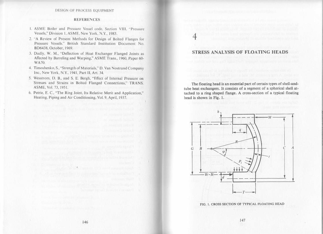
| )tist(;N oI I,l{()(itiss ljQtjIl,MLiNl'
RUt'URf,NCES
L ASME Boiler and Pressure Vessel code, Section VIII. "PressurcVessels," Division l, ASME, New York, N.Y., 1983.
2. "A Review of Present Methods for Design of Bolted Flanges forPressure Vessels." British Standard Institution Document No.8D6438, Ocrober. 1969.
3. Dudly, W. M., "Deflection of Heat Exchanger Flanged Joints as
Affected by Barreling and Warping," ASME Trans., 1960, Paper 60-wA70.
4. Timoshenko, S., "Strength of Materials," D. Van Nostrand CompanyInc., New York, N.Y., 1941,Part II, Art.34.
5. Wesstrom, D. B., and S. E. Bergh, "Effect of lnternal Pressure onStresses and Strains in Bolt€d Flanged Connections," TRANS.ASME. Vol. 73. 1951.
6. Petrie, E. C., "The Ring Joint, lts Relative Merit and Application,"Heating, Piping and Air Conditioning, Vol. 9, April, 1937.
r46 147
4
STRESS ANALYSE OF FLOATING HEADS
The floating head is an essential part of certain types of shell-and-tube heat exchangers, It consists of a segment of a spherical shell at-tached to a ring shaped flange. A cross-section of a typical floatinghead is shown in Fig. l,
w-H-
FIC. I. CROSS SECTION OF TYPICAL FLOATING HEAD

l)ESl(;N 0r, PllocEss EQUTPMENT
Floating beads can be built of forgings or castings. They can alsobe fabricated from formed heads welded into rolled and welded plateflanges or machined forged flanges. Regardless of the material or themethod of fabrication, the floating head must be designed to withs-tand the combined effects of pressure and boltload.
A technique for designing floating heads is discussed in UA-6,Section VIII, Division I of the ASME Boiler and Pressure Vesselcode.' However, the formulas given are approximate and do not takeinto account continuity between the flange ring and the dished head.
In this stress analysisl the flange is assumed to be cut loose fromthe head. A ring moment, M, and a ring load, V, are applied to boththe head and the flange at their junction. These represent the total mo-ment and the total force acting over the junction surface between thehead and flange. M and V are computed assuming that the radial andangular displacements of the flange are equal to those of the head attheir line of junction. Forces and moments acting on the head andflange are shown in Fig. 2. The total bolt load has been treated as acontinuous ring load.
r--GlB
H<-
FIC. 2. FORCES AND MOMENTS ACTINC ON HEAD AND FLANCE
148
and
STI{ESS ANALYSIS OF FLOATINO HEADS
Stress Analysis Due ao Intemal Pr€ssure
Lst Pr be the tube side pressure or the pressure insid€ the floating head,
then, the force H is
H :PtrB24
The dislance e can be determined by
Now,
Therefore,
)t:1.29
-e
^ l.llmt ln(K\ , ,rr: BKr
'r\
- .-/T ^' l
c.:Hl e cot ,o+'q"--q'-il-wh"LIJJ
^ zsin al,, . t\. B 1.65e( +- z \^'*x,/-+ni- x,
0.2'75mt ln(K)
c2c4 ctc5
crc6-c3c4
Kr
.,:f('-'?)/4q - B cot <o 0.35 \/- _ut ' ,-l'.-"\ 4nd sin,pf
c2c6-c3cs
c2c4-ctcs
r49
,:r_i(r_""*)
cot oxt:l - slcot oKt:r- rzsi,

I)rjst(;N oF Pr{(x)ljss EQUIPMENT
Head Stresses
Stress on outside of the head is given by
" _P,R , V cos tp , 6M'0.- z, - oBt 'rst,
Stress on inside of the head is
- P,R . Vcos rp 6M\_ :: -t2t nBt nBt2
Flange Stresses
Bending stress in the flange is given by
":w?-ry)Direct stress in the flange is
s" : L__l n P -"o,,\- ull*l *' \-' nBrl" \8 -"'-l 'l\K'z- r/Resultant Flange Str€sses
Resultant stress on outside of the flange is
57, : Sa _ Sr
Resultanl stress on inside of the flange is
S.r;1 :Sa+56
Stress Analysis Due to External Pressure
Let P" be the shell side pressure or the pressure outside floating head, theforce II will be
, : - '.:t'C t, C 2, C 4 and C, will be the same as worked out earlier for inlernalpressure. C. can be worked out from the relationship
^ .-/ 2str-at \Cr:H{ ecot a+ '"--'-il-wh\I,/
and
150 151
STRESS ANALYSIS OF FLOATING HEADS
- ,,(4(t-Bcot rp 0.15\(":nl _.---.-|\ 44.1 Stn q,,/
Now,
anq,
Head Stresses
Flange Stresses
c2c6- c3c 5
c2c4-c rcs
c rc6- c 3c 4
c2c4-c rc 5
^ - P"R Vcosa 6M\.:-+-]--2t tBt rBt2
-P-R Vcos o 6Ms..: ' + - =2t nBt TtBt'
- O.525n | -. 4Mi\"': arK, \n-;i
. r 1,,(+q --. \ ,,]/K'z+l\r,: -Llr\8-col
e )- v )\K4 )
Resultant Flange Stresses
Slo : 51- 56
Sliz:Sa*So
Stresses with Full Gssket Restnint
In lhis case also, C r, C 2, C 4 and C, will remain unchanged.Also,
cr=;and
Bc u= +ntt
Now

and
c2c4*ctcsWith no pressure applied, stresses in head and flange due to unit force Fcan be determined as follows:
Head Stresses
l)l:Sl(;N ( )lr Pl{()(ILSS liQtJll,MINT
,, c 2(:6- (' 3c 5
c2c4-ctcs
c tco- c rc4
^ V cos e 6M\.:t- nBt rBt2
^ Vcos(p 6MftBt tBt2
^ 0.525n / .. 4M)\" BrKr\ B/
^ /l - /\/K2+ I \J,:l- ll
-
|" \'rBIl\K'- l /
and
Flange Stresses
and
Resultant Flange Stresses
Sy, : 51_ Sr
Syr::Sa*56
The force F is given by the negatiye quotient ofthe values of Sr,, orSy;2 due to int€rnal or external pressure (whichever is higher) and thevalue of Sr,, due to the unit force as determined above.
F:-fl',\ ". -fL.\' \sr,. / -'
\Sr'../Multiplying the str€sses due to unit force by F and combining these
with the stresses previously computed for int€rnal or external pressure(whichever is higher) will give us the resultant outside and inside headand flange stresses in the floating head. If, the resultant stresses are notwithin allowable limits, modifications in design are required.
152 153
STITESS ANALYSIS ()F I LOATINC HEADS
EXAMPLE
Analyze the stresses in the floating head of a kettle type reboiler
clesigned for 310 psi shell side and 100 psi tube side pressure both at
650"F. The flange material is A-105 and h€ad is made of A-515-70. The
head is 0.9375 in. total minimum thick and has inside dish radius of3l.09375 inches. The inside and outside diameters of flange are 34.75 in.
and 3'7.':'5 in. respectively and it is 5.5 in. thick in longitudinal direction
cxclusive ofcounterbore. The inside depth offlange is 3.8554 inches. The
diameter at the gasket load reaction is 35.125 in. and bolt circle diamet€r
is 36.5 in. The shell and tube side corrosion allowance can be assumed tobe 0.0625 inches. The total bolt Ioad is 255,443 pounds.
SOLUTION
Referring to Fig. l, we have
A : 3'7.'7 5 - 2{0.0625) : 37.625 in.
B =34.'15 +20.0625):34.875 in.
C:36.5 in.
c:35.125 in.
R : 31.093?5 +0.0625 + (0.937 s -0.125]112 :31.s625 tn.
t :Q.93'75 - 2(0.0625):0.8125 in.
, (A_ B)u- 2
T: 5.5 -0.0625 : 5.4375 in.
and
q:3 8554 in'
Now,
tlrr : :(c - c): :(36.5 - 35.1 25):0.6875 in.
2ttl
i = : (G - B) :;(35.125 - 34.875) :0. | 25 in.2ZT s 4175
n: ' =-^ ;z;;:6.6923t u.6ll)
(37 .625 - 34.8't s)

l)r,st(;N orr pt{(xt[ss UQUtPMENT
nr : (rr)r : (6.6923)r : 299.7272
a 77 6)5K = r:ao*rr::t'ozss
/14 R7s \*:.,n'(urrr) :sin' r{o.s52s):33.s4"
Ch€ck Up for Internal Pressure
Pr: 100 Psi
-- 100(2X14.875)
": + :9)')lo lb
;-
Kz:
| / nRlt{\3.85s4 - :I s.437s - ::= | : t.62
z \ v.6JJJ //rr s,<rs
r.29 |-:::::::8.0401v u.drz)
| 50R5r-ffi:o.e62s1.5085
t - tr***:0'84990 21121.??2)0!' 2ll,tg78!l _
0.962s
{l ln.
1.6241 :3.6535 in.
|.t (8.040t t299.'7 27 2 (0.8125)0.07585v2 + r :5.8668
34.875 (0.9625)
c 3 : s s,s26lt.624l (1.5085) +
:79,892 in-lb
2(3.8554) 1.5821
34.8'ts - o. 125]- 255,443(0.6875)
8i1910!525r(s34es+-t \+ 34.875 * I j!!f i41)2 \ o.962s / 4(6.6923)1.t75 0.8t2s(0.9625)
:8.5695
^ r.65 f 4{8.0401)1.624t It s =0.8r2s10.9025) Lr
* 34J7s l:s2698/in'
^ ^- -^_[4(3.8ss4)-34.875(1.5085) 0.]5 |1 ":v:':zol a16Je21r.-i--osszsl: - 157.026 lb
t54 155
STI{ESS ANAI,YSIS ()1. I'I,oATINC HEADS
l 9!9i! f102!t -12{22tsj?9!l5.8668(8.5695) - 3.6535(s.2698)
r.6535( - r5?.026) - 7e.892(8.5695)
= - 43,26',7 lb
: -40,562 in-lb5.8668(8.5695) - 3.651s(5.2698)
Head Stresses
.s. _r00(1.5b25r+, 1l.i.u],9.tLr:* or _alf9?l_ . : _ r.828 psr.
2(0.8125) r(34.8?5)0.8125 r(34.8?5X0.8125)'
100(J 1.5625) (-43,267)0.8115 6( -40,562)s,'--2tgjt25) + n(:qj?5lgjtx - n(34.875tt0.8125), :4vuz psl
Flange Sar€sses
\ _ 0.525(6.6e23) -- ( oa ro, _or- 40.s62)8.0401)_ _ 755 psr.
"'-:+.srs(o.8rzsto.so2s \ 34.875 / '| | /41\85541
-, .no.\-, - r., r^r,-ll216"\s' -n{34.815r5r37sle5'526(;8i5 "' /''-- l\0.r638J
: - 1,299 psi.
Resultant Flange Stresses
Sr): - 1,299 -(- 755): - 544 Psi
s711 : - 1,299 +( - 755): * 2'054 Psi
Check Up for External Pressure
P":310 psi.
.. ( - 310)n(34.875)'zH: 4 : -296.129lb
r ,(:.sss+)l.s!4_o.rrrlc3: -296J291 1.6241(1.5085) +: 34.8.7s I
- 255,443 (0.687 s\: - 967'689 in-lb
C6: -296,129l
Now
4(3.8554) - 34.87s(1.5085)
4(6.6923)t .37 5 -u1*]=o'u'"' 'o

and
l)ttst(;N ()tr PR(x:liss tx)(JIPM
,, 5.8668(486.777 ) I 967,68e(5.2698)
31.0223
3.6535 (486,7 77) + 96 7,689 ( 8.5 69 5 )
EN'I'
256,M0 tb
:324,639 in-lbM:31.0223
^ ( - 310) 31.5625t,.:--l-
2(0.8125)
: - 30,550 psi.
Flange Stresses
Head Stresses
S,,(-310)31.5625
2(0.812s)
:23,310 psi.
and
. 256,440(0.833s) 6(324,639)- t(34 8?510^8 t25 - n(34J75X0-8 | 25f
s. : _jj?!16€23) f ,.^ _, 4r324.63er8 040r I'u:34i75(0J 125 10.9625 Lt'o'*t) - 14.8?5 -l: -5'530psi'
I t /r r 6rR\-ls :_ - | _106 Iror _ t.066J)_256.4401..'.:: I l:1.315 psi,-' nt34.8'75)5.43'7s L ---'---' \0 1638/l
Resultant Flange Stresses
Sr":1315 -(- 5530):6,845 psi.
Sri, : 1315 +( - 5530): - 4,215 psi.
Stresses with Full Gasket Restraint
In this case
c,=seI:21187s n-tb
2s6,440(0.8335) 6(324,639)
z(34.875)0.8125 z(34.875)(0.812s)'?
34.875
4(6.6923) 1 .37 s:0.94'15lb
5.8668(0.9475) - 2.7r87 s(s.2625\
31.0223
Now
156
: -0.282 lb
r57
atrtl
S'I'I(USS ANAI,YSIS OF ITLOATIN(; HEADS
:{Ilgrs47.sl ?f 1875(&5621 : _0.63e4 in-lb31.0223
'hererore' r,.:0*#ffi*.;offiffi33rr : -0'055? psi'
irnd ( - 0.282)0.8335( -o-!''ri " ' n(34.875 )0.8125
6{ -0.6394) _ _0.0504 psi.r (34.875)(0.81 25)'
\, _ 0.s2s{6.6e23) [_o.rrr_0,-0.^u?1?-t.oootl:o.oreop,i..^:34875(0.8t 25)0.9625 L "-"- 34.8'15 J
/ | -t -0.2821 \/2.1638\s-l ' ' ll - - l:0.0284 Psi"J - U(34.87s)5.4375l\0. 1638/
NowSr,:0.0284 -0.0396: -0.0112 Psi'
S7r3:0'0284 * 0'0396 =0'068 Psi'
The force F is given by the negative quotient of the two values ofSJi'
thus with internal Pressure
/ - tn54\p: _I _-::: . l:30.206 Ib- \ 0.068 /
and with external Pressure
o: -1-a2ls):ot.sts tu- \ 0.068 /
Stresses Due to lnternal Pressure
and with Full Gssket Restrsint
Multiplying the stresses determined above due to the unit force by the
.orr".pinOlng force F and combining these with the stresses due to
internal pressure as computed earlier, we get
Sr,: - 0.0557(30,206) - 1828: -3,510Psi'srr : 0.0504(30,206) + 4902 : 6'424 psi.
Sr,,: - 0.01l2(30,2061- 544: - 882 Psi'
Sr1:0.068(30'206) - 2054 =0

t)tlsl(;N ( )tr pl{(xjtjss lQtJll,MIN1.
Strcssrs Duc lo llxternal Prossurcand with Full Gasket Resaraint
Repeating the above procedure and subtracting the external pressurc [(]obtain the combined stresses, we get
sa : -0.0557(61,985) + 23,310 _ 310 : 19,547 psi.srr : 0.0504(6 1,985) - 30,550 _ 3 I 0 : _ 27,7 36 psi.
s_/,, : - 0.01 12(61,985) + 6,845 - 310:5,841 psi.S/r :0.068(61,985) - 4,215 - 3lO: - 310 psi.
AII the stress€s determined above due to internal or externalpressure and with or without full gasket constraint are within thcallowable of 30,400 psi (0.8 yield) stress, rherefore, our design is safe.
B
cd
G
h
Nomenclature
Corroded outside diameter offlange, rn.Corroded inside diameter offlange, rn.Bolt circle diameter, in.Corroded radiai thickness offlange, in.Mean gaskel diameter, in.
Radial distance from gasket load reaction to the bolt circle:(c - G)12
Radial distance from corroded inside diameter to the gasketload reaction :(G - B)/2A/Bn3
Ring-moment between flange and head, in-lbT/tInside pressure on the floating head, psi.Outside pressure on the floating head, psi.Inside depth offlange, in.Mean corroded head radius, in.Stress on the outside offlange, psi.
Stress on the inside offlange, psi.
Stress on the outside of head, psi.Stress on the inside offlange, psi.
Km
Mn
P.
q
Re
C
S,,
Jl,i
158159
l.
S'TI{ESS ANALYSIS oT TLOATIN(; HEADS
I Corroded head thickness, in.
T Corroded longitudinal thickness offlange, in.
/ Ring-load between flange and head,lb
w Total bolt load, lb
E One half of central angle of head : sin ' (B/2R )
REFERENCES
ASME Boiler and Pressure Vessel Code, Section VIII, "Pressure
Vessels," Division l, ASME, New York, N.Y., 1983.
Soherns, J. E., "The Design of Floating Heads for Heat Exchangers,"ASME Paper 57-A-247.

5
FIXED TUBESHEET DESIGN
In the chemical industry, heat exchangers are frequently required tobe fabricated of expensive corrosion-resistant materials, and to avoidwaste of such materials it is desirable that tubesheet thicknesses shouldbe no greater than are required to withstand the design conditionsinvolved.
This chapter discusses the design offixed tubesheets in accordancewith the method proposed by Dr. K. A. G. Miller.r It takes into accountthe support given to the tubesheets by th€ tubes and also the weakeningeffects of different tube hole spacings. The tubesheet designed by thrsmethod results in thickness much less than as given by the methodproposed by TEMA'? (Tubular Exchanger Manufacturers Association).The Miller method is generally preferred over the TEMA method foreconomical purposest especially for large diameter alloy tubesheetsdesigned for low internal pressure. There, will not only be a saving rnmaterial but, more important, a saving in the machining time for drillingthe holes in the tubesheet.
Discussion is limited to the box type ofexchanger as shown in Fig. I,since thiscovers almost all types of fixed tubesheet exchangers used thesedays. The tubesheet has been assumed to be simply supported because rnalmost all cases, gaskets are neither full faced nor extended inside boltholes. In any case, if the type ofexchanger or the boundary condition isdifferent than discussed, one should refer to Miller's paper for analysis.
A detailed example follows the short discussion ofdesign procedurein order to present the application of this method for design problems.
t6l

t)ltst(;N ( )tr
Design Procedure
P l{( x jtjss LQTJTPMENT
FIG. 1. . BOX TYPE HEAT EXCHANGER
Typical cross-section of a tube is shown in Fig. 2. Cross_sectionalarea o[ one tube is
nd2 nd,2t: q - q
Cross-sectional area of inside ofshell is
" A:lpz4
Cross-sectional area of tube holes in tubesheet is given by
c:|a,,Cross-sectional area ofshell plate is found using the formula
B: n(D + t)tDeflexion or ligament efficiency can be calculated from the relationshtp
4:P:(A-C)ADetermine
a:E-!:E"B
Working Conditions
Calculate equivalent pressure difference by
P: P, - P, -' 'z""' . A-C
162 163
FIXED TUBESHEET DESION
I)ifferential exPansion is
y = d10t- d"0"
liflective pressure diflerence due to the combined pressure difference P
and the differential exPansion i' is
P":P+y*+
Determine the value ofdimensionless factor
^ | E,na -]" ^rn:tot[tP;,1e-o I D
The values of Gr, G2, G3 and Ga corresponding to the factor l(R can
be read from Table 1.
TABLE r. VALUES FOR Gl, G2' G3 and G4
KR Gr c2 G.
00.51.0t.)2.0
0.8000.8090.8200.871t.012
0.8000.8100.844o.993t.412
+1.000+0.998+0.966+0.836+0.546
1.0001 .002t.o29t.14I .40
2.53.0J.)4.04.5
t.341.882.362.753.10
2.404.246.368.53
10.7 5
+0.121
-0.306-0.608-0.7 4r
-0.727
t;792.252.693.103.47
5.05.56.07.O
8.0
3.43
4.124.825.54
13.1
15.818.72s.333.1
-0.619-0.541-0.5154.529-0.5 64
3.834.184.54s.265.97
9.010.012.o14.016.0
6.266.988.439.88
11.33
41.8)l.t)74.3
101.1
132.0
-0.602-o.642-0.727-0.816-0.907
6.687 .398.81
10.2311.65
18.020.o
i2.8014.25
t67 .2206.4
-o.999-1.091
13.0614.48
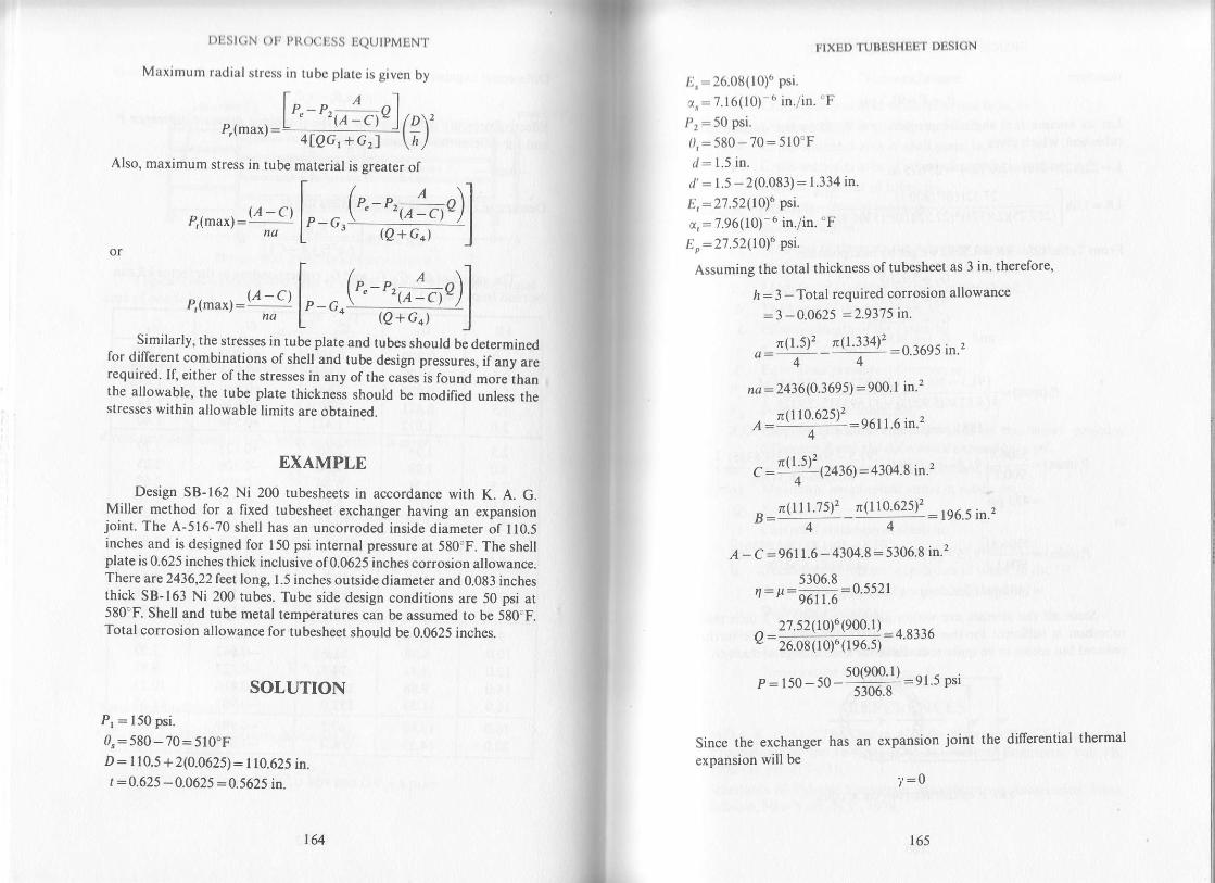
I )tist(;N ()tr t,l{(xItss IQtJtpMLNT.
Maximum radial stress in tube plate is given by
t^^A^-l,-,
^u*, -lt" - t'
t e - c,u I 1 oy'4lQG,+Gzf \ltl
Also, maximum stress in tube material is sreater of
P,r^u*1 :( A _oct
l, - ", (-,;*, t)]
rl-u''A-stl ".@,T31]Similarly, the stresses in tube plate and tubes should be determined
for different combinations of shell and tube design pressures, if any arerequired. If, either of the stresses in any of the cases is found moreihanthe allowable, the tube plate thickness should be modified unless thestresses within allowable limits are obtained.
EXAMPLE
Design 58-162 Ni 200 tubesheets in accordance with K. A. G.Miller method for a fixed tubesheet exchanger having an expansronjoint. The A-516-70 shell has an uncorroded inside diameter of I10.5inches and is designed for 150 psi internal pressure at 580"F. The shellplate is 0.625 inches thick inclusive of0.0625 inches corrosion allowance.There arc 2436,22leet long, 1.5 inches outside diameter and 0.083 inchesthick SB-163 Ni 200 tubes. Tube side design conditions are 50 psi at580"F. Shell and tube metal temperatures can be assumed to be 580"F.Total corrosion allowance for tubesheet should be 0.0625 inches.
SOLUTION
Pr : 150 psi.
0"=580-70=510.FD: r 10.5 + 2(0.0625): 110.625 in.t :0.625 -0.0625 :0.5625 in.
164
the differential thermal
IlxDl)'ruBBsHtit1,r D[slcN
,,.:26.08(10)" psi.
z,:7.16(10) 6 in./in. "F
,i : 5o Psi.
l),:580 - 70:510"Fri:1.5 in.
r/' : 1.5 - 2(0.083) : 1.334 in.
ti, : ZZ.52,tOru Ott.
a,: ?.96(10)- 6 in./in. "F
,ir:27.52(10)6 psi.
Assuming the total thickness of tubesheet as 3 in. therefor€,
ft:3 -Total required corrosion allowance
: 3 - 0.062s :293't5 n.
.. -r(l 5)2 _n(l -334)2 :0.3695 in.,a:4-4-
na : 2436(0.3695) :900. I in''?
n(I10.625)' ^-.,o:""'\"'"' :n6l 1.6 in.'z
-i | <\2c :'"":' ecttt:4304.8 in.2
r(l I l.?51, n(110.625t' : t96.5 in.,B= O, _ a
A - C:s6ll.6 - 4304.8:5306.8 in.'
5306.8 ^ --^.4:It=-:u.))21
27.52(10)6 (900.1) :4.833626.08(10)6(196.5 r
a:
":,50_50-H#:er.5psi
Sinc€ the exchanger has an
expansion will be
expansion joint
?:0
to)
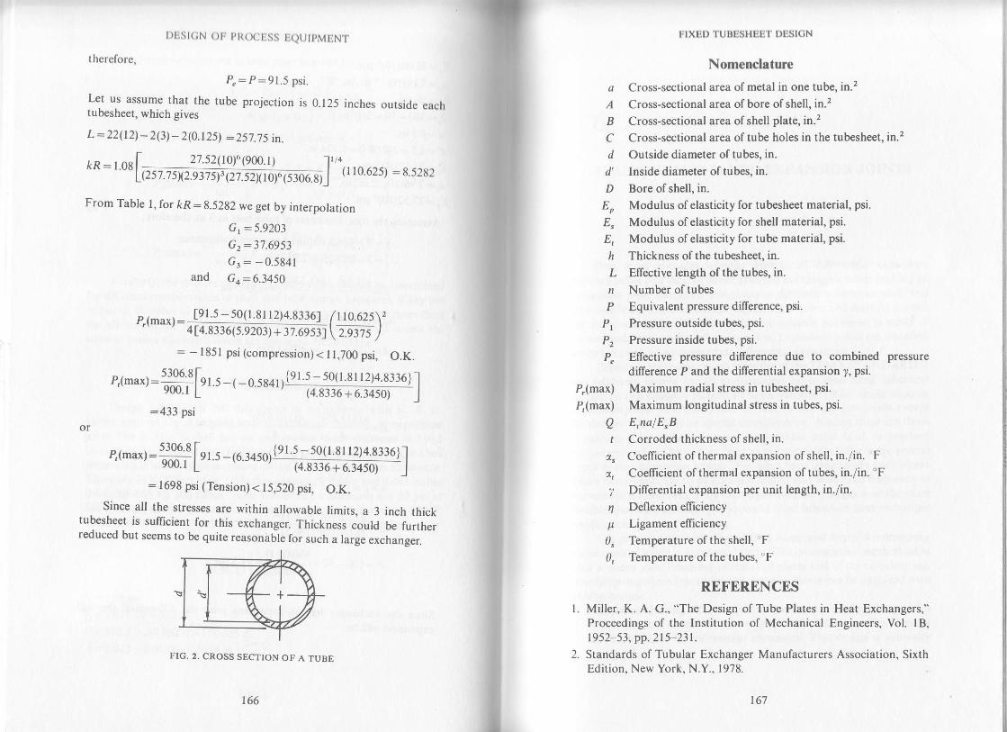
t)1.:st(;N ( )r, pti(xjljss tjQUtpMINT
therefore,
p.: p:91.5 psi.
Let us assume_that the tube projection is 0.125 inches outside eachruoesneet, whtch gtves
L :22(12) - 2(3) _ 2(0.125) :257.7s in.
From Table l, for kR:8.5282 we get by interpolation
Cr : 5 9203
G z:31 6953
6r: - 0 5841
and Gt:6.3450
P,(max):4 14.8336 (s.9203) + 37.69
[91.5 - 50( l.8l l2)4.8jj6]
: - l85l psi (compression) < I1,700 psi. O.K.
I10.625
zws
p,(max) :#1r.5 -( -0 5s4r/1####{l.l:433 psi
:1698 psi (Tension)< 15,520 psi, O.K.Since all the stresses are within allowable limits, a 3 inch thick
tubesh€et is sufficient for this exchanger. Thickness .outa U" iu.it",reduced but seems to be quite reasonable for such a large
"*"nung"..
e,r,nu4: !963 [el.s -16.34591 1 91 5 - 50( l'8 | l2t+ g:lo]1
vw.r L (4.8336+6.3450) |
FIG. 2. CROSS SECTION OF A TUBE
166 t67
a
A
B
a
d'
D
F
h
Ln
P
p
P,(max)
P,(max)
F'IXED TUBESHEET DESION
Nomenclature
Cross-sectional area of metal in one tube, in.2
Cross-sectional area of bore of shell, in.2
Cross-sectional area of shell plate, in.2
Cross-sectional area of tub€ holes in the tubesheet, in.2
Outside diameter of tubes, in.
Inside diameter of tubes, in.
Bore ofshell, in.
Modulus ofelasticity for tubesheet material, psi.
Modulus ofelasticity for shell rnaterial, psi.
Modulus ofelasticity for tube material, psi.
Thickness of the tubesheet, in.
Ellective length of the tubes, in.
Number of tub€s
Equivalent pressure difference, psi.
Pressure outside tubes, psi.
Pressure inside tubes, psi.
ElTective pressure difference due to combined pressure
difference P and the differentialexpansion i,. psi.
Maximum radial stress in tubesheet, psi.
Maximum longitudinal stress in tubes, psi.
Q E,nalE,Bt Corroded thickness ofshell, in.
r" Coeflicient of thermal expansion of shell, in./in. F
z, Coeflicient of thermal expansion of tubes, in./in. 'F7 Differential expansion per unit length, in./in.
4 Deflexion efliciency
p Ligament efficiency
0" Temperature ofthe shell, 'F0, Temperature of the tubes,'F
REFERENCES
l. Miller, K. A. G., "The Design of Tube Plates in Heat Exchangers,"Proceedings of the Institution of Mechanical Engineers, Vol. lB,t952 53, pp.2l5-23t.
2. Standards of Tubular Exchanger Manufacturers Association, SixthEdition. New York. N.Y.. 1978.

6
FLANGED AND FLUED EXPANSION JOINTS
One must consider Yarious aspects of differential expansion
b€tween tubes and shell offixed tubesheet exchangers, when making an
expansion joint selection. Temperature differences between shell and
tuie side fluids cause differential expansion oftubes and shell Asaresult
the tubes are subjected to stress unless suitable provision is made to
accommodate the differential expansion. Expansion joints are installed,
when required, to accommodate differential expansion'
Tubisheet thickness design formulas of the TEMA STANDARDS'are relatively simple for all construction other than fixed tubesheet
desien. In this desisn a factor "J" has a value of 1.0 for shells without
expa'nsion joints, and mostly zero for shells with expansionjoints, except
foi designs which require special consideration. Among these are those
expansion joints which require considerable axial load to produce
movement and are known as "ring expansion joints." There are several
types of ring expansion joints. They have been successfully used where
small movements are to be accommodated and wh€re the frequency of
movement is minimum. They offer significant advantages over the more
flexible thin wall bellows type joints in fixed tubesheet heat exchanger
applications.The procedure as recommended by Kopp and Sayre2 for designing
these typis ofjoints is discussed briefly. This computation method takes
into account joint flexibility of the shell plates and of the circular ring'
The following three types of ring expansion joints can be analyzed with
this technique:L FIat plates with ring Thisconsists of two concentric flat plates with a
circumferential bar at the outer edges. Tbe flat plates can flex to make
some allowance for differential expansion. This design is gen€rally
169

t)Est(iN oF PROCESS EQUTPMENT
used for vacuum service (steam surface condensers). All wetd!are subject to severe stress during differential ;_;;i;"."' "2. Flenged only herds Inthistvd;il;G";;;,ffi'ji"Hl!lii":tl.,1T,1x,.fl
fi ]hlillThe curved shape tends to reduce the ,"*, ""
,f," *"fi#;iiiir.3. Flanged and flued herds Thi
expansion joint.rnliiJtr;'i:11?il'H#,'iffj.liff i,.j:jwrrn concentric reverse flue ^l1l"l Tq.: f,.ra,
"* "IJi,i*fy
expe-nsive because of the fluingoperation. iri" "u-rii Jr,;d;;&"r,the amount of stress significantly.
^-^..Ll._,::l-l'?": discussed applies directly to type I above. However,provrsron ls made to convert the actual cross_section oftyp" iu"J ll",oan equivalent of type I (i.e., square cornered ring, with the same totalleng.th of plare along the centerline)for unuryrir. rnlalirionl #il,predicting the value of ,,J" factor for designing fi;;;;.;;;;; ,"
:::::d** .with paragraph 7.tel of riMA" St;$ffi;;'"r.,:I:n-,C:^. having_ these type of expansion :"i*. l. p."r".[i
^"example is included to demonstrate rhi "r"
.f ;"t;iq; ;;;;;;;.Design Procedure
TYPE I TYPE 2 TYPE 3
FIG. I. RING TYPE EXPANSION JOINTS
..- -Il "*p1ori:l joint of Type 2 or 3 is desired, the dimensions oftnese types should be converted to an equivalent oi Type f
", ioff-o*r,
For Tyrr- 2, L:G _O.2t5rFor Type 3, t: c - O.215(r tr,)For Type 2 or 3, lr : H _0.43r
170
':(+)"
t7l
FLANOED AND FLUED EXPANSION JOINTS
Let E be the modulus of elasticity at design temperature and m be
the Poisson's ratio of expansion joint material. Now,
^Ro
.:ffi(I)hf r Ib:t +t l1- loRpa , , ,< |
L lt-^'11'o ' '-- ,
-Lzla + oJ
F,JD:nffi)At:(2b- LIC
Br:(2a+ L)C
a,:ltt-rtc
n,:lta+Dc
v,:L]+oa,-Le,
v,: -l-o.a,+L-;,
^:fflMoments Drc to Internal Pressure
Let P be tho internal pressure and x be the distance above point I as
is shown in Fig. 1, then

t)Est(;N oF Pt{(xtEss EQUTPMENT
F=KWFt=LW-F
Mt: AzW- ArFM j: B1F _ B2lU
It4:7,4,- p,r 1! rz2
Moments Due to Differential Thermal Movement
Using the proper sign for dillerential movement A (i.e. + if thejointopens and -if the joint closes) determlne
- /D\rr:l;; ly\Lrr'/Mn'=-A'F'Mu'=B'F'Mr=M^r*Frx
Determining Section Modulusof Exprnsion Joint Section
z:+(!-f,+t\6\ r ' -/Str€ss6 Due to Internal pressure
s, =M'z.S, should be determined at x = 0 i.e. at /4, ro x: B at an interval ofone inch by changing the values of M and Z.
Msximum Str€ss rt Test h€sslre
s,: Maximum s, (p) r.s
Stresses Due to Dilfcrcntid Moveme
-M,'z
172
',4t=,
FLANCED AND FLUED EXPANSION JOINTS
S, should also be determined in the same fashion and at the same
distances from / as Sr.
Resulta[t St]esses in Expsnsion Joints
S=Sr*Sz
Thus, the resultant stress at each location from I to B can be
determined by adding S, and S, at the same location Care should be
taken to use the proper sign while adding these stresses. The resultantstress will be compressive if positive and tensile ifnegative.
The pressure, deflection or combined stresses should be less than
the corresponding allowable stresses, otherwise, the design should be
modified.
Allowable Stresses
The movement with respect to each other of the shell plates at the joint
will be determined by the elastic changes in the shell and tubes. This may
cause high stresses locally in thejoint and therefore some plastic yielding,
but any yield in the joint will not cause further movement of the shell
plates, and so will be self-limiting in nature. The portion undergoing
plastic deformation is small in comparison with the portion undergoing
elastic deformation. Therefore the residual strain will be imperceptible.
Thus the prevention of significant plastic deformation does not require
all calculated elaslic stresses to b€ below the yield point, since
appreciable plastic deformation can occur only if the material yields
across the entire area. Thus, ifthe exchanger service is to be a steady one,
the local stresses with this type of loading should always be lower than
twice the yield stress in order to avoid failure by brittle fracture as stated
by Brownell and Young.3Similarly, internal pressure acting on the flat plates in thejoint may
cause them to bulge, but as they bulge. catenary or cupping stresses as
well as bending stresses are introduced, and unless the plates are very
heavily loaded, the bulging will also be self-limiting in nature.
Therefore, the stresses of the following order can be allowed
while designing such expansion joints:
Pressure Strcsses
Maximum allowable Sr = 1.5(Sd"")
Maximum allowable S, : 2.25(S"'n)
173

r'DESIGN
Detlectlon Strsss
Toasl Stress
Therefore,
OF PROCESS EQUIPMENT
Maximum allowable S. = smaller of 2(Srr)
or 4(S0.,)
Maximum allowable S=smaller of 2(Sro)
or 4(S;,)
Calculating Value of J Factor
"/ is the ratio ofthe force to move the expansionjoint one inch to the forceto move the shell and the expansion joint rogitt ".
on" in"i. i. ,i""0earlier, these types of erpansion jointsiequi."-"onria".uur" JJlo"a, toproduce the required movemenr. Thus, the value .r J J""iJ o"determined as follows:By definirion
Fr,: , __-(f.r+r") , *&
where F" the force to move the shell by one inch can readily bedetermined from ..Hooks Law" as:
r'":/!(rd=z(Do=49u
,*opF#LMettods of Calculating F,B€sides the Kopp and Sayre technique Gardnera and Samoiloff havealso stated methods of calculating
_Fr. fr.**"r, .rrf y"t"n""_"iirra:*::T:T^1 ll.Ko?p and Sayre is disiussed here, accoioirg,. *iir,i., can oe determlned as:
Fr=2(F,)(R,)n
But, in accordance with TEMA .I can be assumed to be equal to zero forshells with expansion joints, where
Fr <(Do-t)tEs/loLl
t74 t75
FLANOED AND FLUED EXPANSION JOINTS
EXAMPLE
A 15.25 inches I.D. exchanger is to be equipped with a flanged and
flued expansion joint to be designed to open 0 125 inches in order. to
u""o-rnoa"t" tlie dilferential thermal expansion' The internal design
fressure is 100 psi and the shell is 0.375 inches total minimum thick
inclusive of 0.0625 inches corosion allowance' The expansion joint
material has the following properties:
Code allowable stress at design temperalure: 17'500 psi
Yield stress at design temp€rature:38'000 psi
Modulus ofelasticity at design temperature = 27'6 (10)6pci
Poisson's ratio:0.3
Also, calculate the value of factor '/ for designing fixed tubesheet
assumingthe overall length of shell to be equal to 16 feet'
SOLUTION
The minimum expansion joint plate thickness is assumed to be the
same as the shell thickness' Both corner radii are made equal to J llmes
;l;;;;l;-k"".t. A straisht flange of 0'875 inches (should- be..1.inch
normally) is assumed and the expansion joint as fabricated wrll be as
shown in Fig. 2.
rr:0.375L
=r;Jlrs.2vlDFIG. 2. EXPANSION JOINT IN EXAMPLE CALCULATION
t-i
\4.37 s',
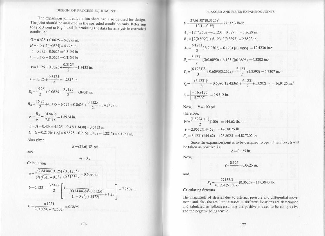
[)ESI(;N OF PROCESS EQUIPMENT
. The expansion joint calculation sheet can also be used for design.The joint should be analyzed in the corroded condition only. Referringto type 3 joint in Fig. I and determining the data for analysis in corrodcdcondition:
G = 6.625 +0.0625 = 6.6875 in.H = 4.0 +2(0.0625) = 4.125 in.
t =0.375 -0.0625 =0.3125 in.tr :0.375 -0.0625:0.3125 in.
oltrsr: I.125 + 0.0625 + '';- : t.3438 in.
o lt?srt:1.125 + -'-:-- :1.2813 in.
lsrs n?rr<R,=:-19.962, +' T":7.8438 in.t2
Ro: rll + 0.i75 + 6.6251q.g62510 n 25 = 14.8438 in.
- R" 14.84381(:d: 7J43s
: t 8924 in'
h: H -0.43r = 4.125 - 0.43(1.3438):3.5472 in.L: Q -0.215(r + r) :6.687s -0.215(1.3438_ 1.2813): 6.r231 in.
Also given,
and
Calculating
E:(27.6)106 psi
m:0.3
,/7.8438(0.3 r 25) /0.31253 \a:-- _:F::I - _ __ l=0.6090in.t2)J3tt - 03'z | \0.3125r/
^ 6.1231L:)a;ono*rr* :o'389s
:7.2502 in.
176 177
FLANOED AND FI.UPD EXPANSION JOINTS
D: 27.6(10)6(0.3125)l= 77132.3 lb-in.
l2(l -0.3, )A | = t2(7.2502)- 6.l23ll(0.3895) :3.262e tn.
81 : [2(0.6090) + 6.1231](0.3895) :2.8593 in.
e, :4!p1t.zs02)- 6.I231I(0.38e : 12.4236 in.'z
a, : {1 1r1o.ooe0) + 6. 1 23 l I (0.3se 5) = 6.3202 in.z
,, :(u ttit)' *o.u oso(3.262\-9!21(2.85e3) :5.730? in.'?
r,: -(6'l2tlt)'-o.6o9ooz.a:r,6'ya!E\ 6.3202) = - 16.9125 in.r
':l+ff] :2,5tzin
Now, P: 100 psi.
therefore,
w:ry1!@l : rr+4.62 tb lin.
F : 2.95 12(144.62) : 426.8025 lb
F r 6.1231(144.62)- 426.8025 =458.7202lb.
Since the expansionjoint is to be designed to open, therefore, A willbe taken as positive, i.e.
A:0.125 in.
Now,
0.125y= - -:0.0625 in.
and
7't 132.3F,: . -=:(o.o62s): 137.38a3 lb.' 6.1231(5.7307)Cdculating Str€sscs
The magnitude of stresses due to internal pressure and differential move.ment and also the resultant stresses at different locations are determinedand tabulated as follows assuming tle positive stresses to be compressiveand the negative being tensile:
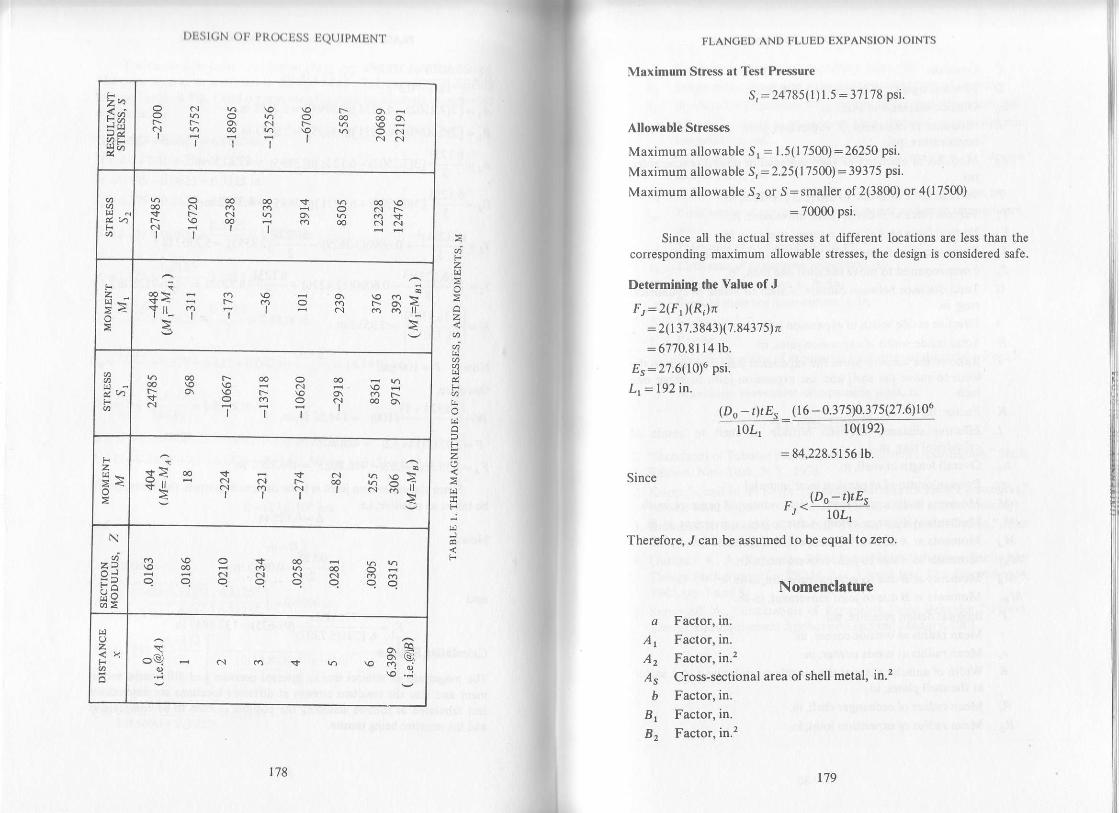
Eotz:oz
o
Fzo
F
DES|(;N oF P l{ocEss EQUTPMENT
2t^Sa;
NF
E S € 3 I S $a|:l.-o\NF-v)\oFql 6 6 (.) \O \.r dc.l' I 'i -i I cr"r
!?ooocov('l€ C.l .Oco; osFcn(/)o\v..h90g?..roo'll
oo \oC.l a-
z
E
O\ \O.is(?IF-O\<N .") .o ll\
d, v)F
F q E = R 3 G:R - I E 3 R gh..TTTI
2>a:
t^jE oo v F sr .o,, H N ...r Fr .d g P+$.ll qr .? a' -i ii H llertt :
N
6z?
(/)E
g E : $ N R H:q q q q c c qc
()z
,n o Fi Y\
oQ * c.r o rfqi
r78 t79
FLANCED AND FLUED EXPANSION JOINTS
Maximum Saress at Test Pr€ssure
S,:24785( I ) 1.5:37178 Psi.
Allowable Stresses
Maximum allowable sr : 1.5(17500):26250 psi.
Maximum allowable Sr:2.25(17500): 39375 psi.
Maximum allowable 52 or S:smaller of 2(3800) or 4(17500)
: 70000 psi.
Since all the actual stresses at differcnt locations are less than the
corresponding maximum allowable stresses, the design is considered safe.
Determining the Value of J
Ft =2(F r)(R)n:2(t37 38a3)Q.8437sln:6770.81 14 lb.
Es:27.6(10)6 psi.
L, -- 192 in.
(Do- tltEsl0L1
(r6 - 0.375)0.375(27.6)106
10(1e2)
:84,228.5156 lb.
Since
- -(Do -r)tEst, =-ioLTherefore, ./ can be assumed to be equal to zero.
Nomenclature
c Factor, in.
Ar Factor, in.
A2 Factor, in.2
,4" Cross-sectional area ofshell metal, in.2
6 Factor, in.
Br Factor, in.
B2 Factor, in.2
l)L.sl(;N ol, PRoctiss UQUTPMENI'
(' ConstantD Flexural rigidity of expansion joint, lb-in.
Do Outside diameter of shell, in.
E Modulus of elasticity of expansion joint material at designtemperature, psl.
Es Modulus of elasticity of shell material at design temp€rature,psi.
F Vertical force at B due to int€rnal pressure, lb.
Fr Vertical force at B due tojoint moyement, lb.
FA Vertical force at I due to internal pressure, lb.
Fr Force required to move the expansion joint one inch, lb.
Fs Force required to move the shell one inch, lb.
C Total distance between outside of shell to inside ofcylindricalring, in.
fi Effective inside width of expansion joint, in.
H Total inside width of expansion joint, in.
./ Ratio of the force to move the expansion joint one inch to theforce to move the shell and the expansion joint together oneinch
KL
Llm
MMrMA
M^MB
M",p
riR
Factor, in.
Effective distance between outside of shell to inside ofcylindrical ring, in.
Overall length of shell, in.
Poisson's ratio ofexpansion joint material
Moments at distance x from ,4 due to internal pressure, inlb.Moments at distance x from 1 due to joint movement, in-lb.
Moments at ,4 due to internal pressur€, inJb.Moments at .4 due to joint movement, in-lb.
Mom€nts at I due to inl€rnal pressure, in-lb.
Moments at B due to joint movement, inlb.lnternal design pressure, psi.
Mean radius at outside corner, in.
Mean radius at inside corner. in.
Width of annular plate at the outside considering a unit sectorat the shell plates, in.
Ri Mean radius of exchanger shell, in.
Ro Mean radius of expansion joint, in.
180181
III.AN(;LD AND III,UIiI) IiXPANSIoN JOIN'TS
S Combined stress in thc expansion joint, psi.
Sr Stress in the expansion joint due to internal pressure, psi.
52 Stress in the expansion joint due to differential movement, psi.
S.,. Allowable stress in expansion joint material at atmospherictemperature, psi.
Sr." Allowable str€ss in expansion joint material at designrFmharar',rc nei
Sl Maximum stress in expansionjoint due to test pressure, psi.
S", Yield stress of expansion joint material at design temperature,DSi.
ttrw
Y,
z
Thickness of exchanger plate, in.
Thickness oI expansion joint plate, in.
Lateral load on span L, lb./in.Vertical distance from corner 1{, in.
Factor, in.2
Factor, in.3
Section modulus of expansion joint plate at distance x from ,4,
in."
A Maximum movem€nt of expansion joint, in.
REFERENCES
"Standards ofTubular Exchanger Manufacturers Association j' SixthEdition. New York. N.Y.. 1978.
Kopp, S., and M. F. Sayre, "Expansion Joints for Heat Exchangers,"ASME Misc. Paper VoL 6, No. 211 (1950, ASME annual meeting)
Brownell, L. E., and E. H. Young, "Process Equipment Design," JohnWiley and Sons Inc., 1959.
Gardner, K. A., Report to TEMA on Fixed Tubesheet ExchangerDesign Background for TEMA Par. 3.3 and Par.7.15. December 14,
1963, pp. 7 and 8.
Samoiloff, A., "Evaluation of Expansion Joint Behavior," Power,Design and Equipment Application section, January, 1961.
1.
3.
5.
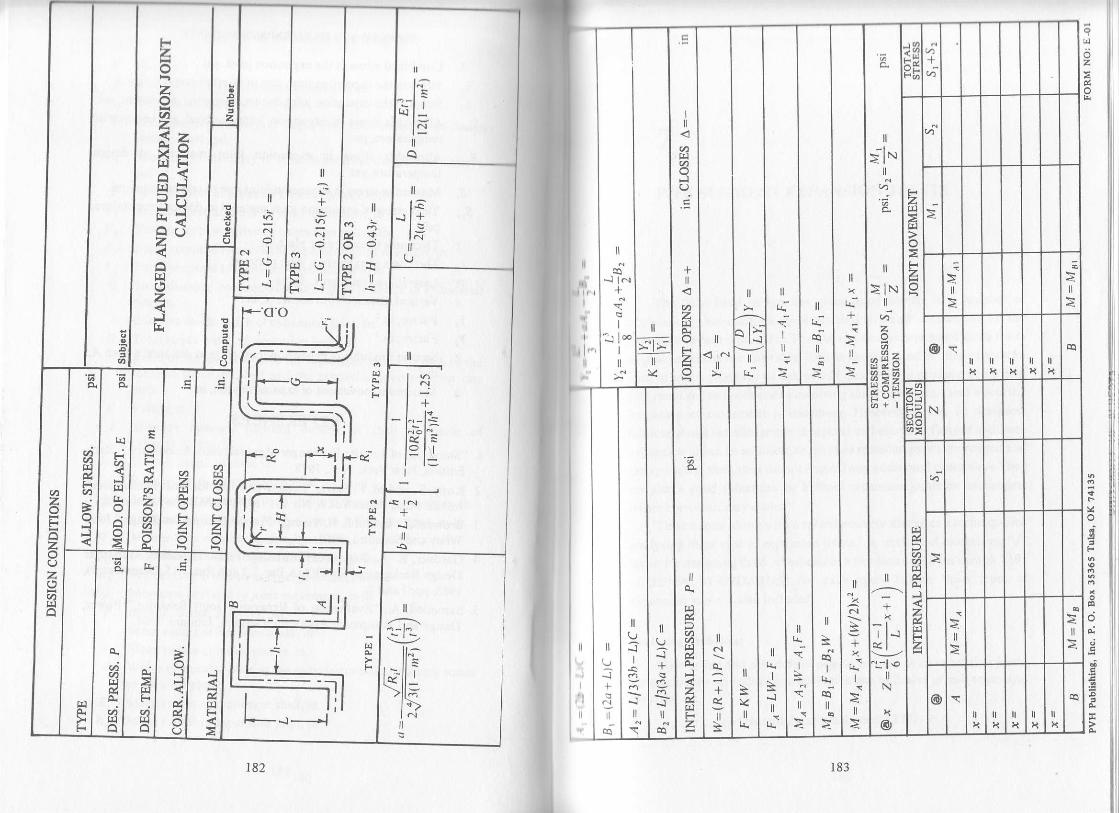
C'z
tl
/--'-:-\--l-
ll^
--lllq _\Jt-,.t(,t.
(q
Il
ztnz<zX=rIJFa\<
'JY:^<z
z
ll
oNIrI]9Fr rr>'''
lla:+
i
F \./>':k-r
caNIF\
L, 's
I
...1
+,;
ll
k:+:
{
-l\. lN
>lNv)za
-fr7-axdvl2 zdYiF :'.
;Ht,t-
":il .otl
N
x@
t.-
:I
{l
;
!-
tl
a
I
r4
o;
+
ztrl
tiv < l..l
rr l(\-t_
I
I l.oI
ll
I
rl,
tl
lG.
l..l
U
tl
t.\t-:l-rl',ol^LloltI
+*l
vtzF
z()zaalI]
l.]
ra
JT&
.,<
=+
II
:s*1
lla:.c
Il\
iI
II
+
\
tl
Q*t
I
*l
llU-1
n
rq
F]
F.l
zFz
el1
;
F
4
7
PIPE SEGMENT EXPANSION JOINTS
The flued-head design has given good service in a number of
applications, but occupies considerable space and is expensive for the
movement which it provides. Thus, in some cases expansion joints made
of pipe segments are desirable. This is another kind of ring-expanston
joint in which pipe may be halved and quartered to produce a ring lt is
also restricted to applications involving small movements and where the
frequency of moYement is minimum However, it can be designed'
fabricated and installed much cheaper than bellows or flanged and flued
expansion joints. In addition, ring-type expansion joinrs are rugged and
heavy walled. thus, they do not require any additional protection' They
are also a good substitute for bellows expansion joints on exchangers
where corrosion maY occur.l
This chapter along with a solved example discusses a technique for
analyzing these type of expansion joints 2 A method of calculating "J"
factor for designing fixed tubesheets in accordance with paragraph 7'191
of TEMA STANDARDS3 for exchangers having these types of
expansion joints is also included.
Analyzing Technique
Choose size and schedule of pipe to be used as an expansion joint'
Determine the corroded pipe wall thickness exclustve of mill tolerance'
which is
r:(Nominal wall thickness)(0.875) - c
185

I)ESI(;N oF' PR(X]ESS
In general, t should not be lessthickness.
EQUIPMENT
than the corroded shell
;$E
--_tgxchanger__FIG. I. DEI,INITION OF SYMBOLS
. In order to usethis analy$is tneratio r/b should be less than 0.1. prpesize or schedule should be altered until the above conaition i"."ii.ti"O.
Now the mean radius of expansion joint as shown in Fig. l, is
a:0.s(d)+(b-c\Determine
u:;J12(1-z.2lSaresses Due to Internal Pressure
Stresses due to internal pressure can be calculated as follows:Maximum meridian bending stress is given by
si :o.e55p(t - -' t-''' (o!)u'
Maximum circumferential membrane stress is
si :0.955p(l - n') t'" ( !!\'''
Maximum Stress at Test hessure
s,:(Greater of si or s;r(fu)r.s
Stress€s Due to Axial Movement
If not already given, the maximum
plate
186
required expansion joint
187
PIPE SECMENT EXPANSION JOINTS
movement due to differential thermal expansion or contraction can be
calculated by using the following relationship:
tr: (0,a, _ 0,a")
A positive value of A indicates expansion whereas a negativevalue indicates contraction.
Internal pressure also causes some movement, the nature ofwhich, depends upon the type of corrugations. Inner corrugationscause expansion and outer corrugations cause contraction and are in-dicated by positive and negative signs respectively. Thus, if, there are
an equal number of inner and outer corrugations, the resulting move-
ment due to internal pressure will be zero. This will also be the case
when we use expansion joints made of pipe segments,
Total end force required to obtain the desired movement can be
determined as follows:For 4 <g <40, the relationship for maximum movement is
^ 0.s7'7 PbnJt - m'^:
-Er'Rearranging the above equation to get the relationship for axial
force B we get
LEt2
where
and C is a constant whichinterpolated from Table 1.
Now, th€ value ofA can be plugged in the above equation to obtain
For p <4, maximum movement is given by
^ CPb3nA:--;-;
4uD
4A,aD-
Chsn
Et3D: _tzv-m-)varies with the value of p and should be

t)ESt(;N oF PR(XIESS EQUTPMENT
Now, the stresses in the expansion joint resulting from the desir€daxial movement can be determined using the following relationships:
Maximum meridian bending stress can be calculated from
-.. l.$Pf ab ltrrJi :=--l ---
|- znat lt2 Jl _m2 JMaximum circurnferential membrane stress is
-,, 0.925pf ab(t _ m2yltt3"r: 2"", L___V_ l
Combined Stresses
-Stresses due to internal pressure and axial movement can be
combined algebraically to obtain the resultant stresses as follows:Resultant meridian bending stress is
st :si +siResultant circumferential membrane stress is
s'?:si+'liIf the pressure, deflection or combined stresses as determined above
are within the corresponding maximum allowable, the design is safe,otherwise, modifications in design are required.
Allorrble Saress€s
This type of loading will not result in plastic lelding of expansionjoint material since the portion undergoing plastic deformation is smallin comparison to the portion undergoing elastic deformation. This hasalready been discussed in detail in the chapter on ttanged and fluedexpansion joints. Thus, strcsses of the following order can be allowedwhile designing such expansion joints:
TABLE r, - vARtATIoN or C wtn a
188 189
PIPE SECMIJNT EXPANSION JOINTS
Pr€ssure Stresses
Maximum allowable Si or S;: 1.5(Sd.")
Maximum allowable Sr : 2.25(S.,-)
Dellection Stresses
Maximum allowable S'i or Si:smaller of 2(Sno)
or 4(Sr"")
Combined Stresses
Maximum allowable S, or S, : smaller of 2(Srr)
or 4(Sr"")
Calculating Value of J Factor
As already discussed J is the ratio ofthe force to move the expansion
joint one inctr to the force to move the shell and th€ expansion joint
iogether one inch ./ is one when no expansion joint is used and ismostly
eq"ual to zero when bellows type expansion joints are used But' the type
under consideration requires considerable axial loads to produce
required movement and J in such cases should be calculated as follows:
Bv definition t., I"-rr 'F r F
'J, rr., ,*.i
Where F", the force to move the shell by one inch, can readily be
determined from "Hooks Law" as:
F":41?.t
_r(Do _tltE"
and f, the force to move the exPansion joint by one inch is
For 4 < p<40, Ft=Et2
0.577bn
For P<4' Ot::*
But in accordance with TEMA, J can be assumed to be equal to
zero for shells with expansion joints, where
Fr <(Do-t)tEslloL

tll.:st(;N ( )tr pt{(xjtiss IQtJtpMtiNl.
EXAMPLE
. Design carbon steel expansionjoint orjoints made of pipe segmcnlrto accommodate the movement due to diiferential t t .rrui .* p?n.ionbetween shell and tubes in a heat exchanger. naateriU oil"".i-Xr" r",shell is carbon steel and tubes are made oinickel. The shefLi" a"J"""i f".150 psi. inrernal pressure at 580.F. Meral
"rnp.r"ur*r'i* liiir-.n.ff
and tubes are 530'F. Length offace to face oftubesheets i, iiz.zs ir"n.,and uncorroded inside shell diameter is 110.5 tnches. Shefipf"i"
" 6.OZSin. thick inclusive of 0.0625 in. corrosion allowance. nir. i"il"rl" tn.value of lactor J for designing fixed tubesheet for this e;;;;:;.-*
SOLUTION
Try a l0 inch schedule 100 (0.718 in. wall) pipe and referring to Fig.l, we have
O: ).J /J tnt:0.718(0.875) - 0.0625 =0.56575 in.
thus
/ 0.56575
,:JJ?5:0.1052>0.1But..since rhis ratio is very close to 0.1, it is assumed ro satisfy therequtrement ol using the technique discussed.
uslng two expansion joints i.e. one near to each tubesheet, we have
n:4AIso
d:110.5 +2(0.0625): I 10.625 in.
L:2) l. l5 rnm:0.30:580-70=510oFa"= 7.16(10)-6 in./in. 'F4:580 - 70:510"Fa,:7.96(10)- 6 in./in. 'FE:26.08(10)6 psi
4 =26.08(10)6 psi
a:0.s(110.62s) +(s.375 -0.0625) =60.625 in.
190
and
t91
and
PIPE SECMBN'T EXPANSION JOINTS
,, - (s 37sf . fixr -at\ :2:tsts- 60.625(0.56575) "
Stresses Due to Internal Pressure
si : 0.e55( I soX | - 0.3' 1"0 [60 i4f!1t-l'''
= t+,zr t p'iL (u.)b) /)r I
Maximum Stress at Test Pressure
s,: 14,960(l)1.5 :22,440 psi
Stresses Due to Axial Movement
A : [(s l0)7.96(10)- 6 - 510(7.16) 10- 6] 25',1.'t s : o.r0s2 tn
Since g < 4, the applicable formula for P is
4LaDD__' - Cb3n
where
26.08(10)6(0.56575)3= 432A'73 lb-in.
12(l -0.3'.)
and C can be interpolated from Table 1, for p:1.7835 we get
si : 0.e55(r50x1 -o.r,l-',.[ffiffi]"" : r4roo n.i
c :0.7216
^ 4(0. 1052)60.625(432,47 3l ^,P:':ffi#:24'6tstb
D:
I nerelore
Now
|.63(24,615)/
2r(60.625)0.56575[ 60.625(s.3!) 'l',. : l,eot priLto.soszs)t.r/t - to:F I
si o.s25t24,6tsl [(60.625X5.375X1-0.3')-]"' : 1.030 o.i2zr(60.625)0.5657s f (0.56575f I

l)Est(;N oF PR(X:ESS EQUIPMENT
Combined Stresses
s1 : 14,960 + 1903 : 16,863 psi
S, = 14271 + 1030:15301 psi
Allowable Stresses
Maximum allowable Si or Si : 1.5(15000) = 225q0 t.1Maximum allowable S,:2.25(15000):33750 psi
Maxirnum allowable S'i or 51:smaller of 2(30000)
or 4(15000) : 60000 psi
Maximum allowable S, or S, :60,ffi p5i
Since, all the calculated stresses are within the corresponding maximumallowable, thus the design is safe.
Calcuhting J Factor
Since 4 <4. Therefore
o,:ffi##:233,e80rb.(D,-r")r"4
10L
(11r.75 - 0.625)0.625(26.08) 106
10(2s7.75)
:702,749.7575 tb.'
Since F, < Do - t")r"E"/I0I, therefore J can be assumed to be equal tozeto.
Nomenclature
a Mean radius of expansion joint, in.,4" Cross-sectional area ofshell metal, in.2b Outside radius ofexpansion joint pipe, in.c Shell corrosion allowance- in.
C Constantd Corroded inside diameter ofshell, in.D Flexural rigidity of expansion joint,lb-in.D, Outside diameter of shell, in.
E Modulus of elasticity of expansion joint material at desrgntemperature, psi.
192 r93
L
m
n
D
P
sis'i
sisi
PIPE SEOMENT EXPANSION JOINTS
E" Modulus of elasticity of shell material at design temperature,psi.
Fr Force required to move the expansionjoint one inch, lb.
F" Force required to move the shell one inch, lb.
J Ratio of the force to move the expansion joint one inch to theforce to move the shell and the expansion joint together oneinchLength of face to face of tubesheets, in.
Poisson's ratio of expansion joint material
Number of semicircular corrugations
Internal design pressure, psi.
Axial force required for expansion joint movement, lb.
Maximum meridian bending stress due to internal pressure, psi.
Maximum circumferential membrane str€ss due to internalpressure, psi.
Maximum meridian bending stress due to axial force, psi.
Maximurn circumferential membrane stress due to axial force,psi.
Sr Resultant meridian bending stress in expansion joint, psi.
52 Resultant circumferential membrane stress in expansion joint,psi.
S",. Allowable stress in expansion joint material at atmospherictemperature, psl.
Sd"" Allowable stress in expansion joint material at designtemperature, psl.
Maximum stress in expansion joint due to test pressure,psi.
Yield stress of expansion joint material at design temperature,DSi.
t Corroded expansion joint pipe thickness exclusive of milltolerance" in.
r" Uncorroded thickness ofshell plate, in.
a" Coefficient of thermal expansion of shell material at metaltemperature, in./in.'F
r, Coeflicient of thermal expansion ol tube material at metalt€mperature, in./in.'FShell metal temperature in "F - 70'F
Tube metal temperature in 'F - 70'FConstant
Maximum required movement of the expansion joint, in.
sr
g
tl
p
A

3.
t.
l)ltst(;N ( )tr Pt{(x:uss IiQT.JtPMENT
REFERENCES
Rubin, F. L., "Choose Heat Exchanger Expansion Joints Carelully,"The Oil and Gas Journal, November 3, 1975.
Roark, R. J., and W. C. Young, "Formulas for Stress and Strain," FifthEdition, McGraw-Hill Book Company, 1975.
Standards of Tubular Exchanger Manufacturers Association, SixthEdition, New York. N.Y.. l9?8.
t94 195
8
YERTICAL VESSELS SUPPORTED BY LUGS
The choice of the type of supports for vertical vessels depends on theavailable floor space, the convenience of location of the vessel accordingto operating variables such as the size, the operating temperature andpressure and the materials of construction.
Various kinds of supports for vertical vessels have been discussed byBrownell and Young' in detail. Lugs offer many advantages over othertypes of supports. They are inexpensive, can absorb diametral expansions,are easily attached to the cylinder by minimum amounts of welding, andare easily leveled and shimmed in the field. However, a footnote afterparagraph UG-29(e) in Division I of ASME Code for Pressure Vesselsz
cautions against supporting of vessels through the medium of lugs unless
they are properly reinforced. In other words, each case should be analyzedthoroughly to insure that the shell is not overstressed.
Vertical sh€lls supported on lugs require consideration of two importantfactors:
1. The additional stress of the support forces when combined with theworking stress of the shell must not increase the stress in the shell
above the allowable limit.2. The support should not restrain the stressed shell so it becomes too
rigid to flex under normal changes in working pressure or loads,
The following types of stresses are developed in the shell supported onlugs:
1. The internal or external pressure on the shell, along with its weight,causes tangential and longitudinal stresses in the shell.
2. Eccentricity of this type of support results in a radial force on theshell which causes bending stresses in the ring ofthe shell (from thebending moment) as well as axial tensile sresses (from the tensileforce), both of which act tangentially.

DESI(;N OF PROCESS EQUIPMENT
3. The radial force causes radial shear stresses in the shell, and $alongitudinal force causes longitudinal shear stresses, bothadJscontto the lug. However, these strcsses are so small that thcy rrtoften disregarded.
After the proper analysis of the forces involved, the various stresrGlmust be combined to detemine the maximum normal and shear stressot,If the resulting stresses are excessive a simple study of the indiyidual stressorwill indicate what portion of the lug is underdesigned and shouldbe strengthened.
For example, the bending stresses may be excessive inficating thstsome type of stiffener ring.should be attached to the shell between supporteto substantially increase the moment of inertia of the shell section therebydecreasing the bending stress.
The method of analysis presented in this chapter is based on thet€chnique discussed by Blodgett., It allows us to calculate stresses in thcshell at the location of lugs and also gives the procedure for sizing stif-feners, if required.
Analyzing Technique
(a) ( h)
I,](;, I , RADIAL I:ORC!] DISTRItsUTION ON SH!]LL DUE TO LUC LOAD
Let F be tlle nraxirnunl lotd on each lug then thc resulting lo|gitudinalmoDl€nl on thc shell duc to eccentricity will be
lV=FLAIso
196
lt'
r97
VERTICAL VESSELS SUPPORTED BY LUGS
Now, only a portion of the shell beyond the lug is assumed to with-
stand the flexural stresses due to moment M. This assumption results in
conse ative stresses since it disregards the reinforcing effect of the remainder
of the shell as well as of the heads of the vessel. A rigorous determination
of the effective width of shell that resists these stresses, requircs a laborious
mathematical analysis. For simplicity, the shell with stiffeners can be com-
pared to a curved beam with an extremely wide flange. Von Karman4
suggests that an effective width of the flange on each side of the stiffening
web is approximately
The value of '?" should be limited to a maximum of 12 ts.
The moment M applies radial forces to the shell having a distributionsimilar to that of bending forces, i. e. maximum at the outer fibers and zero
along the neutral axis. It is assumed that the radial force applied to effective
shell width g would decrease linearly to almost zero at its outer limits. Totalhorizontal force /2 on the shell will be as shown in Fig. 1(a). The resulting
distribution of radial forcefi on a unit wide shell ring is indicated in Fig. 1(b).
Now, mom€nt Mcan be expressed in terms of moment of areas of force
distdbution diagram about t}Ie neutral axis, which gives:
M = 2 f, (+)r(+ t\, z r, o I rI.+)
=fth2 +frc(3h:2s )bo
={{nz +zsn+zsz)
=!Ur*rxo*u)l
Therefore, radial force fi, applied to the unit shell ring due to moment Mcan be expressed as
6MTF+|T67ET-
\lin'--T
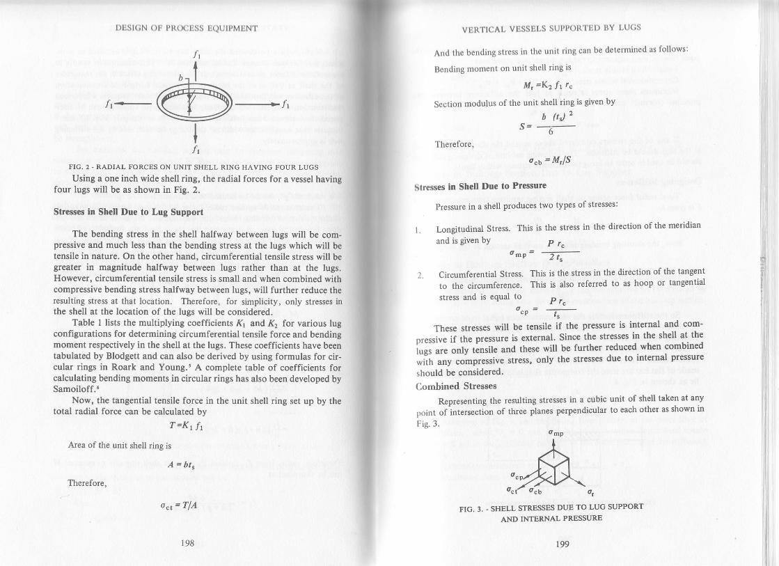
l)DSl(;N ( )lj PR( )(i uss LQUIPMENT
FIG. 2 - RADTAL FORCES ON UNIT SHELL RING HAVING FOUR LUGS
Using a one inch wide shell ring, the radial forces for a vessel havingfour lugs will be as shown in Fig. 2.
Stres6e6 In Shell Due to Lug Support
The bending stress in the shell halfway between lugs will be com-pressive and much less than the bending stress at the lugs which will betensile in nature. On the other hand, circumferential tensile stress will begreater in magnitude halfway between lugs rather than at the lugs.However, circumferential tensile stress is small and when combined withcompressive bending stress halfway between lugs, will further reduce theresulting stress at that location. Therefore, for simplicity, only stresses inthe shell at the location of the lugs will be considered.
Table I lists the multiplying coefficients rK1 and,l(2 for various lugconfiguratiom for determining circumferential tensile force and bendingmoment respectively in the shell at the lugs. These coefficients have beentabulated by Blodgett and can also be derived by using formulas for cir-cular rings in Roark and Young.s A complete table of coefficients forcalculating bending moments in circular rings has also been developed bySamoiloff."
Now, the tangential tensile force in the unit shell ring set up by thetotal radial force can be calculated by
T=Krfr
Area of the unit shell rine is
A=bts
o4= TfA
198
I
Itl
Therefore,
199
VERTICAL VESSELS SUPPOIT'IUI) I}Y LUCS
And the bending stress in the unit ring can be det€rmined as follows:
Bending moment on unit shell ring is
M,=K2f1r"
Section modutus of the unit shell dng is given by
b ftJ2s= -----
Therefore,
o"6 = M'lS
Slresses in Shell Due to Pressure
Pressure in a shell produces two types of stresses:
L Longitudinal Stress.
and is given bY
l. CircumferentialStress.to the circumference.stress and is equal to
o"p
This is the stress in the direction of the meridian
P r"-mp 2 \
This is the stress in the direction of the tangent
This is also referred to as hoop or tangential
P r"=--
These stresses will be tensile if the pressure is internal €nd com-
or"*iu" ii th. pr.rrur. is external' Since the stresses in the shell at the
lu", u.e onlv tinsile and these will be further reduced when combined
*ir, unv .otnpt.tsive stress, only the stresses due to internal pressure
should be considered.
Combined Stresses
Representing the resulting stresses in a cubic unit of shell taken at any
point ofintersection of thlee planes perPendicular to each other as shown in
Fig.3. omp
FIG, 3. - SHELL STRESSES DUB TO LUG SUPPORT
AND INTERNAL PRESSURE
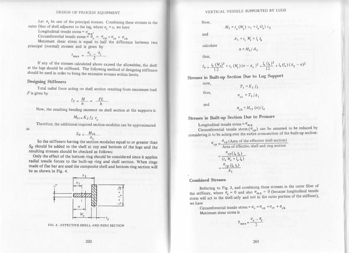
If any of the stresses calculated above exceed the allowables, the shellat the lugs should be stiffened. The following method of O"rignin; ,tiff.n.r,should be used in order to bring the excesstve stresses within limits.
Designing Stiffeners
Total radial force acting on shell section resulting from maximum loadF is given by
+^ M FL,"= h = h
Now, the resulting bending moment on shell section at the suppo s is
M,1=K2 f 2 r.Therefore, the additional required section modulus can be approximated
as
SP = M='r
So the stiffeners huuing the s"Jttion .odulus equal to or greater than54 should be added to the shell at top and bottom of the lugs and theresulting stresses should be checked as follows:
Only the effect of the bottom ring should be considered since it appliesradial tensile forces to the built-up ring and shell section. When rrngsmade of flat bar are used the composite shell and bottom ring section willbe as shown in Fig. 4.
|)|Sl(;N Olr Pl{O( j tjSS tjeutpMLNT
Let or be one of the principal strcsses. Combining these stresses in theouter fiber of shell adjacent to the lug, where o. = o, we have
Longitudinal tensile stress = o_ ".Circumlerential tensi]e stress
j 6" = o"n + o", + o"oMaximum shear stress is equal to half the difference between two
principal (normal) stresses and is given byo"-o,
ts
FIG. 4 . EFFECTIVE SHELL AND RING SECTION
+
200 20r
VBI\'llCAt, VUSSIil'S SUPtORTEI) llY
Now,M1= t,(w,) r1 +/"(r") x2
andAr = t, lU, + ls ts
calculaten=Mr/Ar
thus,
r t, lW,l3 + t tw ttn - x. )2 + /s (ls )r
F /s (ts, (x, - r)2'n=_i t2
Stresses in nuil-t-op S"ctio" Due to Lug Support
now,
thus,
Tr=Ktfz
o", = T1fA,
ando,jo= M'1@)lI'
Stresses in Built-up Section Due to Pressue
Longitudinal tensjle stress = om P
Circumferential tensile stress (it"o) can be assumed to be reduced by
considedng it to be acting over the entiri cross-section of the built-up section:
^ o"^ (Area of the effeciive shell section)""0=mo"p(l' t")=GilrTtt
Combined Stresses
Referdng to Fig. 3, and combining these stresses in the. outer liber of
tfr" ,tiii"n r, ifr"re 4 - O "na
also o.o = 0 (because. longitudinal.tensile
.ir.r, *iff ""i in th" shell only and not in the outer portion of the stiffener)'
we haveCircumferential tensile stress = oc = ocp + oct + ocb
Maximum shear stress is
- o"--o,'mrx- 2

t)Est(;N oF Pt(ocESS EQUIPMENT
If the resulting str€ss€s are excessive, the stiffener size should berevis€d until the stresses are within allowable limits.
Number ofLugs
Values for'l\l
Values forK2
2
3
468
0.000o.2890.5000.8661.207
0.3180.1890.1370.0890.066
TABLE I - MULTIPLYINC COEFFICIENTS FOR CIRCUMFERENTIAL TBNSILBFORCE AND BENDING MOMENT IN SHELL AT THE LUCS
EXAMPLE
Analyze the stresses at the lugs on an A-515-?0 shell of a 24 in. I.D.Vertical exchanger designed for 640 psi. internal pressure at 660o F andhaving .75 in. thick shell inclusive of .125 in. corrosion allowance. Theexchanger is to be supported by two I ft. high lugs, and the total weightof the exchanger is 16910 pounds. The bolt hole in each base plate islocated at a distance of 8.25 in. from the outside of the shell. If the shellis found to be overstressed, provide th€ stiffeners to adequately reinforceit so that the stresses are within allowable limits.
SOLUTION
F= 1691012= 8455lb
ts = .75 - .125 = .625 n\.
L = 8.25 in.
r.. = 12.125 r .3125= 12.4375 in.Now-'
M = 5455 (8.25) = 69754 in-lb
Determining the followings as shown in Fig. I
\/6EIT1AtinI = -----t- =l4in'(12ts'hence oK'
202 203
VERTICAL VESSELS SUPPORTED IJY LU(;S
anq
= 211I lb /inch ring of shell
Stresses in Shell Due to Lug Support
From Table l, for shell having two lugs, we have
Kr = 0'0 and Kz = 0'318
Therefore
r=(0)(2111)=0A = | ('62s) = '625 ir'2n =ONow -ct -
. M=.318 (2111) 12.4375 = 8350 in-lband
s = 1 (.625)2 16 =.0651 in. 3
t}Ierefore,
o"b = 83s0/.0651 = 128260psi
Stresses in Shell Due to Pressure
640 fl 2.4375\o = :-::-:-:::-::J- = 6368 Psimp 2 (62s)and
^ = 640 (12.437 s)""p- ___
3E- = I j/JO psl
Combined Stresses
Longitudinal tensile stress = omp = 6368 psi (O'K' )Circumferential tensile stress = oc
=12736+O+128260= 140996 psi (excessive)
Maximum Shear Stress = rmu*
= 140996 - O
2
= 70498 psi (excessive)
Since the stresses are excessive, stiffeners should be added to bdng the
shell stresses witlin allowable limits.
Designing Stiffeners
f- , 84ss (8.T) = serr ru,, = ___1;
M,1 =.318 (5813) 12'43'15 = 22992 in-lb
DBSICN OF PROCESS EQUIPMENT
Using 4-515-70 stiffeners, the allowable tensile stress for stiffener
material at 6600 F is l?320 psi. Therefore, the approximate section modulus
of the stiffener isltoo?
S* = *n32o = 1.32?5 in.3
Let us provide 3 5/8 in. wide and 5/8 in. thick stiffeners at the top and
bottom of lugs around the circumferenc€ of exchanger and check the
magnitude of resulting stresses in built-up section as follows:
Referring to Fig. 4, we have
ts= .625 in.,\= .625 in., ll = 3.625 in.,
ts=.625+2(1.4)=3.425in.," r = 1.8125 in' and
x z = 3'9375ln'Now
Mr = .625 (3.625) 1.8125 + 3.425 (.625) 3.937 5 = 12.5352ir..3
and
A t = .62s (3.625) + 3.42s (.62s) = 4.4063 in?
Thus
12.5352n = ___;_-;;;__ = 2.gul4g in.+,+uoJ
Therefore
.625 (3.625t 3 .,^-, 3 4251.625)3,"=ff + (.62s) 3.62s (t .0323)2 + =::::-:::-+ 3 .42s (.62s) (r .0927)2 = 't .s2o9 ' na
Stresses in Built-up Section Due to Lug Support
11 =0(5813)=0 thus, oct=0
and
^ 22992 (2 8^^a\o"t = --jiis- = 8697 psi
Stresses in Built-up Section Due to hessure
omp = 6368 psi
_ 12'136 (3.42s) .62s""P = -----766-- = bl6/ Psi
204 205
VERTICAL VESSELS SUPPORTED BY LUGS
Combined Streeses
Referring to Fig. 3, and combining these stresses in the outer fiber of
the stiffener we have
o. =0 o_p =0oc = 6187 + 8697= 14884psi. O.K.
i - 14884 - o ='7442 osi. o.K.max- 2 '
Ar
b
c
IrlzF
sh
Since all the stresses are
acceptable.
within allowable limits, our design
NOMENCLATURE
Area of unit shell ring, in.z
Total area of effective shell and ring section, in.2
Unit width of shell ring, in.
Corrosion allowance, in.
Radial force on unit shell ring, lb/in.
Total radial force on shell, lb
Maximum load on each lug, lb
Effective shelt width on each side of lug, in'
Height of lug, in.
Moment of inertia of effective shell and ring section about neutral
axis, in.a
KL Mdtiplying coefficient for circumferential tension in shell at lugs
Kz Multiplying coefficeint for ben&ng moment in shell at lugs
/, Effective shell length, in.
, Distance of centerline of bolt hole from outside of shell' in'
M Maximum moment on shell due to eccentric loading, in -lbM, Sum of the moments of areas of effective composite section about the
' outside of stiffener, in.3
Mt Bending moment on unit shell ring, in -lbMr, Maximum bending moment on sltell, in -lbl1 Distarce of centroid of composite section from the outside of stiffener,
ln.P Maximum internal Pressure. Psi

s
t
| )ESt(;N OIr Pt{(XitSS EQUTPMENT
/c Mean shell radius in corroded condition, in.
S Section modulus ofunit shell ring, in.3
Approximate section modulus of the stiffener, in.3
Uncorroded lhickness of shell plate, in.
Thickness of stiffener, in.
Corroded thickness of shell plate, in.
Tangential tensile force on udt shell dng, lbTangential tensile force on shell, lbWidth of Stiffener, in.
xr Dstance of centroid of sliffener from outside {L, ), n.x2 Distance of centroid of corroded shell from outside of stiffener. t-(
ttr- + +, tn.
o. Resultant circumferential tensile stress, psi
o"b Tensile bending stress due to lug support, psi
ocp Circumferential tensile stress in shell due to internal pressure, psio"t Tangential tensile stress due to lug support, psiomp Longitudinal tensile stress in shell due to internal pressure, psi
o, Principal stress at principal plane, psi
ot Allowable tensile stress for stiffener material at shell design temperature,psi
r-", Maximum shear stress, psi
5.
4.
1.
REFERENCES
Brownell, L- E., and E. H. Young, "Process Equipment Design," FirstCorrected Printing, John Wiley & Sons, Inc., April, 1968.
..r,SME Boiler and Pressure Vessel Code, Section VIII, "Pressure Vessels,"Div. l, ASME, New York, N. Y., 1983.
Blodgett, O. W., "Design of Welded Structures," Third Printing, TheJames F. Lincoln Arc Welding Foundation, August 1967.
Karman, Von, "Analysis of Some Thin-Walled Structures," ASME PaperAER-55-19C, Aer. Eng., Vol. 5, No.4, 1933.
Roark, R. J., and W. C. Young, "Formulas for Stress and Strain." FifthEdition, McGraw-Hill Book Company, 1975.
Samoiloff, Alexander, "Investigation of Stress in Circular Rings,"Petroleum Refiner, Vol. 26, No. 7, July 1947, pp 99-103.
tr/"
Tt1w
206 207
9
VERTICAL VESSEL LEG DESIGN
Legs are most commonly used to support small tanks and vessels. lfvessels are located out of doors, the wind or earthquake load as well as
the dead weight load should be considered in the calculation. However,
as leg supported vessels are usually of much smaller height than skirtsupported vessels, the wind loads may sometimes be a minorconsideration. The wind or earthquake load tends to overturn the vessel,
particularly when the vessel is empty. The wcight ofthe vessel when Iilled
with liquid tends to stabilize it.This chapter discusses the complete design analysis oflhese types of
suppods. It gives the method of calculation for forces and moments due
to ;ind and earthquake based on the criteria presented in the UniformBuilding Code.r These forces and moments can also be calculated in
accordance with the ANSI Standard A - 58.1'?, ifdesired. After the size o[the required legs to withstand the greater ofthe wind or earthquake force
is established, the stiength ofthe selected leg support should be checked,
in accordance with the technique presented herein and as also has been
explained by Brownell and Young s
Cllculating Wind Forces
If the vessel is to be exposed to wind, first of all, the base shear and
moment should be determined. After the wind pressure zone for the
location of vessel is established from Fig. 1, the wind pressures' p, for
various heights can be determined from Table l. The effect of shell and
legs should be considered separately.

l)l1Sl(;N ( )lr l,l{()(itjSS l:etJIpMljNT
FIG. 1. . WIND PRESSURE MAP OF THE UNITED STATES
lR"prod.u""q from rhe Uniform Buitding Code. t976. wirh ihe permission ofThernrernafionat ( onrerence ot Building Officiats)
208 209
VtsI\TICAL VESSEL LEG I)ESIGN
WIND I'RI.SSURF P WHLN THL HORIZONTALCROSS SEC]ION SOUARE OR RECTANCULAR
HEICHTZone ft.
MAP AREAS20 25 30 40 45 50
less than 30 20 25 2S 30 35 40
30 to 49 25 30 40 45
sO to 99 25 30 40 45 50 55 60
l0O to 499 30 40 60 't0
TABLE I.WIND PRESSURE FOR VARIOUS HEIGHT ZONES ABOVE GROUND
Shell
Wind force should be determined by applying the factor for cylindrical
structure excluding appendages to the vessel and then adding the forces
due to the attached elements, if any.
S., the wind shap€ factor for cylindrical structure excluding
appendages is 0.6. Now
therefote
A": Dh
F": .4"(s,)p
Legs
Calculate ,4, in the direction of the wind. Also
Sr : 2.0(constant )
F t: A t(S r\P
Total Wind Shear and Overturning Moment
I' - F !F
and
Mw:F'.(hl2+D+FL(12)
Wind force and moment due to platforms (if any)should beadded totheones calculated above to get the resulting shear and moment due to
wind.
Selecting Approximate [,eg Size
The approximate size of lhe required legs to withstand the total
horizontal force { can be chosen from Figure 2. This size can be further
checked for its adequacy for earthquake force' if the geographical
location of the vessel requires such.
thus
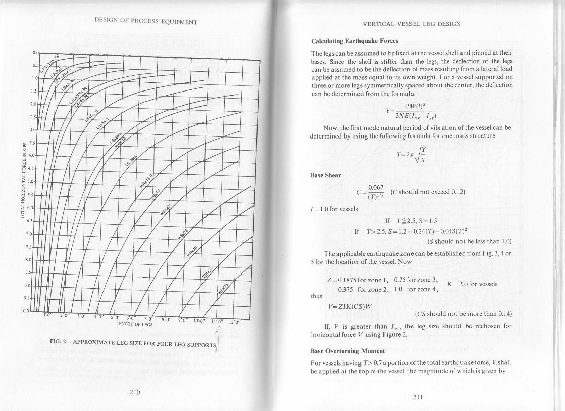
F 5.0
5.5
| )llst(;N I )t l,t{( ,(.Lss LQL.JIt'MLNT
LENGTH OF LECS
210 ltl
VEIITICAL VESSEL LEC I)ESICN
Calculating Earthquake Forces
The legs can be assumed to be fixed at the vessel shell and pinned at theirbases. Since the shell is stiffer than the legs, the deflection of the legs
can be assumed to be the deflection of mass resulting from a lateral loadapplied at the mass equal to its own weight. For a vessel supported onthree or more legs symmetrically spaced about the center, the deflectioncan be determined from the formula:
2W(t)'3NE(/,_+ r... )
Now, the first mode natural period of vibration of the vessel can be
determined by using the following formula for one mass structure:
Base Shear
IvI: Zn Ivs
o 067C:=,, (C should not exceed 0.12)(r, -
1: 1.0 for vessels
If T:2.5, S: l.sIt T>2.s, S:r.2+ 0.24(n 0.048(T)'z
(S should not be less than 1.0)
The applicable earthquake zone can be established from Fig. 3,4 or5 for the location of the vessel. Now
Z -0.1875 for zone l, 0.75forzonel, K=2.0foru.rr.l,0.375 for zone 2, 1.0 forzone4,
thus
v: z r K(cs)w(CS should not be more than 0.14)
If, / is greater than F., the leg size should be rechosen forhorizontal force I/ using Figure 2.
Base Overturni[g Moment
For vessels having T> 0.7 a portion of t he total eart hquake lbrce, 4 shallbc applied at the top of the vessel, the magnitude of which is given by

l)Est(;N oF PR(XIESS EQUIPMENT
I
:i (
..'l ---t'.
I
.\-\-
FIG. 3.. SEISMIC ZONE MAP OF THE UNITED STATES
(Reprodrced f.om the uniform BuildinB Code, 1926, with the permisston of Thetnternational Conference of Building Officials)
i
ie;=5! E ;;! i !_: ;5 " -: P
; I 5- i9 9!E!:Eri9li E;= E'.;; s!1!= :; ii:r'!!i;;;. EEEi EE9E F
H t':b Er!;_q a::-= i=_ E
@ :: i:I E::tI !:i€
iiiiill=;;B ee
212 213
VERTICAL VESSEL LEC DESION
PACtFtC OC€tN
FIG.4. - SEISMIC ZONE MAP OF ALASKA
XAUA I
/-)#,,oP r(*4) M0L0m I
FIG,5. - SEISMIC ZONE MAP OF HAWAII(Reproduced from the Uniform Building Code, 1976, with the permission of TheInternational Conferenc€ of Buildins Ofiicisls)

l)Esl(;N o| PRoc[ss IQUIPMEN'I'
4 = 0.07 TY(4 should be limited to
0.25 I/ maximum and strould be assumed
equal to zero for T!0.7)
Considering the weight, l{ uniforrnly distributed along the shelllength, the remainder of the earthquake torce {V-F) resolves to a
ttapezoid, the extended non-parallel sides of which intersect at the base
as is shown in Figure 6. For this iype of load distribution the base
overturning moment can be determined by the formula:
ME:Flrlr+l(v-F)(H3 -ti)l@, - Pl
v -F
FIG. 6. - DISTRIBUTION OF EARTHQUAKE FORCEALONG THE VESSEL LENGTH
Wind Forces for Vescels with Braced Legs
The technique discussed earlier can be used to determine the wind forceand moment except that the projecied area of the bracing exposed to thewind should also be taken into consideration with legs.
Earthquake Forces for Vessels with Braced Legs
The static deflection, { is found by determining the change in length ofthe bracing resulting from a total lateral load equal to the weight of thevessel.
Now, the maximum force in the brace will be
":(#):214 2t5
VERTICAL VESSEL LEG DESIGN
Therefore, the change in length of brace can be determined by
a _ (lcs)b
(AEThus,
Y=4-sin 0
The period of vibration can be deternined by using the relationship
The rest of the calculations to determine the earthquake force and
moment will be the same as discussed for unbraced legs.
Checking Strength of the Legs
To check the adequacy of leg size, the vessel support can be consideredas a column and allowable fiber stress under concentric axial load isgiven by
F _ t8ffn'"-r+(f13666"2,
The maximum fr ratio should not exceed 120 and also the
maximum allowable fiber stress should be limited to 15000 psi.
Designing Legs for Axial Loading
The required cross-sectional area of each leg for axial compression canbe found from
A,: pt/F"
Ifthe value of .4,, as calculated above, is greater than the actual area
of selected leg, ,4, choose the one with higher area and recheck thestrength of the leg.
Designing Legs for Eccentric Loading
When the legs are attached to the vessel with distance 'a' between the
centerline of the leg and the centerline ofthe yessel plate, this produces an
eccentric loading and an additional stress in the leg supports. This stress
is siven as
i

I)tisI(;N Ot? PI{(XJESS EQUIPMENT
f"":P::sr
The effect ofeccentricity ofleg supports which are welded directly tothe vessel is almost negligible. However, this should not be neglected ifthe legs are attached dilferently.
Designing l*gs for Wind or Earthquake Loading
The legs for this type of loading have to resist the greater of wind orearthquake force as well as the moment about base. This momenteventually is converted to direct load on the legs, the magnitude ofwhich depends on leg location corresponding to the direction of force.This load should be added to lhe dead load while calculating directstress. Analysis of most generally used cases are discussed in figures 8 and9.
The force F (greater of F* and /) at the base produces bendingmoment which is comparable to considering the leg as a beam fixed atone end but guided at the other end with a concentrated load at theguided end. This type of loading produces the same bending moment atboth ends and the magnitude of maximum bending stress in leg is givenby
fb-G lN)t/2sr
However, to obtain more conservative results in actual analysis infigures 8 and 9, the leg is considered as a cantilever with the load Fconcentrated at the free end.
Designing l*gs for Combined Inading
When leg supports are subjected both to direct loads and bendingproduced by wind, earthquake or eccentric loads, the sum of the axialcompressive stresses divided by the allowable column stress, plus thebending stresses divided by the allowable flexural stress shall not exceedunlty, or
Sum of direct stresses Sum of bendine stresses <l
where Fr, the maximum allowable bending stress in the column shouldnot exceed 20.000 Dsi.
216 217
VERTICAL VESSEL LEG DESIGN
L€g Design Analysis
A technique for analysis is presented for four angle supports with F acting
in two directions. The moment due to eccentric load is assumed to be
negligible. A typical cross-section of the angle along its various axis is
shown in Fisure 7.
FIG. 7. . VARIOUS AXES OF AN ANGLE
Let
M:Grealet of Mn or ME
Now select the configuration of supPorts corresponding to the
direction of force F and analyze using the proper figure as described
below.Direction of "F" as shown in Fig. 8.
WMPt:i' P': ot
- /*,.'F - I=, F
":zrt^* *Ll' ":at..j Lj,t!, . L:F: t.
Leg,,a..y.:-_ A r",
t-ec't* 1.:Pt ' 1^:l^' t
,4' - s"."
Using approximate values we can simplify and say:
w M 0.l0F lLeC"a" l;:4-+ D,i. h: S*
Irg" o-L:#, ,=ti::'
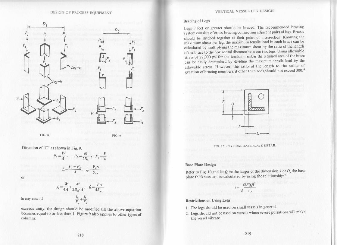
l)ust(;N oF pl{()(jLSs TIQUtPMENT
"-fl<>
DPtinr?tL LJ".,*-o'\-(
.171"s"u'
S-.n19t (P*'\y'*r
'2t
P1
1
6I\
[1JI Ltu-'h-4
F-rE' r'-rn, nlr' rl. F-
lP.
IP'
".17,rt|J
P,
tltltJ
frI uF4rYlflrhtsil--4
"rl
"ln]"".i-,1
,p
tlIJ
FIG.8 FIG.9
Direction of "F" as shown in Fig. 9.
-WM-Fpr:V, ,r:rU t Fr=O
" P,+P. F,.tl"= A-. Jb:i:
.w M ^ F.tJ.:4A+2DiA.h:+s*
f.,foF,- h
exceeds unity, the design should be modilied till the above equationbecomes equal to or less than 1. Figure 9 also applies to other types ofcolumns.
In any case, if
218 219
VERTICAL VESSEL I,E(; I)ESICN
Bracing of Legs
Legs 7 feet or greater should be braced. The recommended bractng
sysiemconsists ofcross-bracingconnecting adjacent pairs of legs Braces
should be stitched together at their point of intersection' Knowing the
maximum shear per leg, the maximum tensile load in each brace can be
calculated by multiplying the maximum shear by the ratio of the length
ofthe brace io the h;rizontal distance between two legs Using allowable
stress of 22,000 psi for the tension member the required area of the brace
can be easily determined by dividing the maximum tensile load by the
allowable stress. However, the ratio of the length to the radius of
g;ratlon of Uracing members, ifother than rods,should not exceed 300 4
FIG. TO. . TYPICAL BASE PLATE DETAIL
Base Plate D€sign
Refer to Fig. l0 and lel 0 be the larger of the dimension '/ or O, the base
Dlate thickness can be calculated by using the relationship;"
Restrictions on Using l.€gs
1. The legs should be used on small vessels in general
2. Legs lhould not be used on vessels where severe pulsations will make
the vessel vibrate.

l)us t(;N otr pRo(iltrss tQUtpMuNT
EXAMPLE
A 54 in. inside dia., 10 ft. 6 in. tangent to tangenl carbon steel verticalvessel having ellipsoidal heads, is 0.375 in. thick. The biggest overheadnozzel size is 8 in., and the vessel has 4.5 in. thick insulation. Themaxlmum operating weight is 16,000 lbs. and the vessel is to besupported on four 7 ft. high legs. Neglecting the elfect of earthquake,design the leg suppods if the vessel is to be located in a 40 psf wind zone.
SOLUTION
Shear for the vessel and legs can be calculated separately and thencombined in order to come up with the maximum shear at the base.However,for simplicity and to be on the conservative side, the maximumbase shear can be calculated by assuming the vessel as a cylinder ofdiameter d throughout its length including legs.
The wind diameter in feet is given byD: [vessel I.D.+2 (vessel thickness)+2 (insulation thickness)
+overhead line size+2 (insulation thickness) 1 (extra for externaladditions)l/12.
Thus D in this case is
D : ls4 + 2(0.37 5) + 2(4.s) + I + 2(4.5) + r2ll 12 : 7.'t 3 tr.
Total length ofthe vessel:tangent to tangent l€ngth +inside depthof head +top head thickness + height of the tegs:(126 + 5414 + 0.3j5+ 84)/12: 18.6563 ft.
Therefore
f :(Wind diameter)0.6(Wind force)total length of vessel: 7.73(0.6)30(18.6563) :2595.8 lbs =2.5958 kips
From Figure 2, for a vessel with a wind force of2.595g kips, choosethe leg size as I,Y4 x 13.
Now for this leg, r:0.991 in. and l:84 in. Therefore
- 18000t -: -- = 12865 psi. < 15000 psi. O.K." I + [842118000(0.991)r]
t/r:84/0.991:84.8 < 120, O.K.
L
220 221
VERTICAL VESSEL LEG DESIGN
Check Leg Str€ngth for Axial Loading
Area of the sel€cted leg, ,,4 = 3.82in.'l The load to be supported by each
les, tu*g:oo* ,oPt: q
therelore
A,: 4000112865 :0.3109 in.'? < 3.82 in.2 O K'
or maximum direct stress is given by
4rrx)fF#= t047 psi < 12865 psi, o.K.
Check Leg for Wind
The bending sfess in each leg due to base shear can be calculated from
r. -(2595 8t4)8412
=5001 psi <20000 psi, o.K.'" 5.45
Check Leg for Combined Loading
Itr-t t!L< t
f "
ft
lna1 sfnl.' + ---'=0.3314<l.O.K.12865 20000
Bracing of Legs
Try 2" x2" x!" angles as bracing and arrange as shown in Fig. I I Then
mlnlmum
Length of each brace:J272 +692:74 ir'.
minimum radius ofgyration oleach brace:0.391 in.
Length :A:,rr.roo,o.*.radius of gyration 0.391
Area of each brace:0.938 in.2
Shear in each leg: "T t : uon b
maximum tensile force in each vace:o+sffi): nlal tu
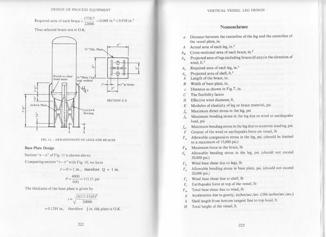
SECTION X.X
FIC. 1I. , ARRANGEMENT OF LEGS AND BRACES
Base Plate Design
Section "x - x" of Fig. I I is shown above.
Comparing section "x - x " with Fig. 10, we have
J:O:I in., therefor€ Q = I in.
^ 4000p: ... _ t. psiol o,
The thickness of the base plate is given by
t)tilit(;N ( )l. pt{(xttjss tjQtJtpMtrN'I.
Required area of each brace: 1778 7 :0.089 in.'1<0.938 in.'?" 22000
Thus selected brace size is O.K.
VEI{TICAL VISSEL LE,G I)ISIGN
Nomenclature
a Distance between the centerline olthe leg and the centerline of
the vessel plate, in.
.4 Actual area ofeach leg, in.2
,4s Cross-sectional area ofeach brace, in.2
.4, Projected area of legs including braces (ifany) in the direction ofwind, ft.2
.4, Required area ofeach leg, in.2
A" Projected area of shell, ft.'?
b Length ofthe brace, in.
B Width of base plate, in.
c Distance as shown in Fig.7, in.
C The fleiibility factor
D Effective wind diameter, ft.
E Modulus ofelasticity of leg or brace material, psi
f Maximum direct stress in the leg, psi
/, Maximum bendingstress in the leg due to wind or earthquake
load, psi
f", Maximum bending stress in the l€g due to ecc€ntric loading, psi'
F Greater of the wind or earthquake force on vessel, lb
F" Allowable compressive stress in the leg, psi. (should be limited
to a maximum of 15,000 Psi')
F B Maximum force in the brace, lb
Fh Allowable bending stress in the leg, psi. (should not exceed
20,000 psi.)
F" Wind base shear due to legs, lb
F, Allowable bending stress in base plate, psi. (should not exceed
20,000 psi.)
F" Wind base shear due to shell, lb
F, Earthquake force at top ofthe vessel,lb
F. Total base shear due to wind, lb
g Acceleration due to gravity, inches/sec'/sec. (386 inches/sec'/sec')
lr Shell length from bottom tangent line to top head, ft'
H Total h€ight ofthe vessel, ft.
I
lr
I
l
I'
l1
I
l'
l1
I
20000
=0.1291 in., therefore j in. thk.plate is O.K.
Notch to cl€ar
222 223
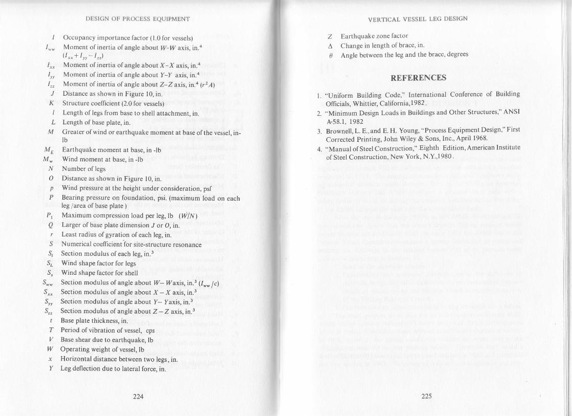
r)Est(;N orj PRocEss EQUTPMENT
/ Occupancy importance factor (1.0 for vessels)
1",. Moment of inertia of angle about W-W axis, tn.a
11,,+1lI-1"")1,, Moment of inertia of angle about X-X axis, in.a1,, Moment ofinertia ofangle about Y-Y axis, in.a
1"" Moment of inertia of angle about Z-Z axis, in.4 (r2,4)
J Distance as shown in Figure 10, in.
K Structure coefficient (2.0 for vessels)
I Length of legs from base to sh€ll attachment, in.I Length of base plate, in.
M Greater of wind or earthquake moment at base ofthe vessel, in-tb
ME Earthquake moment at base, in lbM - Wind moment at base, in JbN Number of legs
O Distance as shown in Figure 10, in.p Wind pressure at the height under consideration, psfP Bearing pressure on foundation, psi. (maximum load on each
leg /area of base plate )Pt Maximum compression load per leg, lb (4N)Q Larger of base plate dimension ./ or O, in./ Least radius ofgyration ofeach leg, in.S Numerical coefficient ior site-structure resonanceg Section modulus ofeach leg, in.3
S" Wind shape factor for legs
S, Wind shape factor for shell
S,. Section modulus of angle about 17- tlzaxis, in ! (I*. lclS*, Section modulus of angle about X - X axis, in.3
Sr" Section modulus of angle about Y- Yaxis, in.3
S,, Section modulus of angle abolt Z - Z axis,in.3r Base plate thickness, in.T Period ofvibration of vessel, cps
/ Base shear due to earthquake, lbl/ Operating weighl of vessel, lbx Horizontal distance between two legs, in.Y Leg deflection due to lateral force, in.
22s
t.
VERTICAL VESSEL LEG DESIGN
Z Earthquake zone factor
A Change in length ofbrace, in.
0 Angle between the leg and the brace, degrees
REFERENCES
"Uniform Building Code," International Conference of Building
Officials. Whittier, California,l982."Minimum Design Loads in Buildings and Other Structures," ANSI
A-58.1, 1982
Brownell, L. E.,and E. H. Young, "Process Equipment Design," First
Corrected Printing, John Wiley & Sons, Inc., April 1968.
"Manual otsteel Construction," Eighth Edition, American Institute
of St€el Construction, New York, N.Y.,1980.

10
ASME CODE SECTION VlrI, DrvIsIoN 2
I,ICU TTS COMPARISON TO DIYISION 1
History of Division 2ri-r" nSft4g code committee has continually modified' revised' and
exoanded the Section VIII of the pressure vessel code ever since it was fi$t
;;;;;; ilis. the oti6na criterion was a factor of 5 between work-
ioJrtr"r, *O ultimate tensile strength Back in the 1930's-the American
Peiroleum lnstitute and ASME developed a pressure vessel co-de wrtn a
,"i",V f"*- of 4' In an attempt to conserve materials during World War
U, the ASME adopted the code with the lowest safety factor'*' *-nii"t ift" *1tt' in the eally 1950's, ah API-ASME committee and the
main committee ageeil that the revised Section VIII on pressure vessels
;;;;;;; lhe"continuing code' In earlv 1955 the ASME Boiler and
Pressure Vessel Committee orgaruzed a special committee to review and
.uulout" th" following in the existing Section VIII of the pressure vessel
qode (now designated as Division l):1. Basis of the allowable stresses'
i. Experimental ancl analyticat investigations -of
the influence of
mierials, design and other factors on the performance ot pressure
vessels as conducted by the Pressure Vessel Research Committee
of the Welding Research Council'
3. Practices used by other countries in setting allowable stress values'
ift" rnul" purpose of all this was to make recommendations which
*oUJotiti". modem technology's latest analytical design techniques to
afiive at higher allowable stresses without sacrific€ or rcduction of safety'
fr, iSf8, }t"o*"""r, the special committee realized an urgent need of the
".*,-"tio" code for nuclear pressure vessels' Therefore' they issued a
it"ii"r sJ* uI tto*.tp*did to t*o Dvisions) in 1958 and published
tlle first edition in i963' Retumhg to their original assignment and after
227.

| )tist(;N Otr ptr()oljss IQUtPMENT
tlro cxpericnce ol producing Section lll, the special committee issued theinitial draft of Division 2 of Section VIII in January of 1967 and rrublishedthe first edition in December of 1968. Both Division 2 of Section VIII.and Section III had safety factors of 3.
IntroductionDivision 2 of Section VIII for pressure vessels entitled .,Alternarrye
Rules" covers minimum requirements for the design, fabrication, inspec-tion and certification of pressure vessels that are prohibited by the Dvisionl. Consequences ofthese rules may be summarized as follows:
1. Pressure vessels above 3000 psi can be designed and manufacturedto comply with these rules and can thus be code stamped. Thisextension of pressure limits encompasses a large number of vesselsthat were previously constructed as specials, or in many sraresconstructed without reference or comparison to an establishedand recognized code.
2. The need for special state regulations for such vessels has beensignificantly reduced.
3. More economical vessels can be designed and manufactured as aresult of advances in technology with respect to working stresslevels, design, inspection and quality control procedures.
4, Restrictions and imposed on the use and initallation of vesselsmade under Division 2, since the basis for the vessel design de_pends on a specific service for a fixed location and thus are par_ticularly applicable to the vessels used by the chemical and otherprocess industries.
Design Criteria of Division 2Division 2 permits higher working stress levels at the expense of a
significantly more detailed stress analysis, which is based on maximumshear theory, on more stdngent material testing and more careful qualitycontrol. Equivalent margins of safety are maintained despite the higherworking stress leyels. It permits application within the ASME code, oftechnology that was previously applied only to pressure vessels designedoutside the scope of Section VIIL
This division depends on a detailed indentification of those stressconditions that actually exist, rather than on simplified rules and arbitrarystress limits. Tresca's ma.:rimum shear theory is used as the analyticalprinciple, so that limits are based on actual stress intensity rather than onarbitrary stress.
In addition to detaited stress analysis fatigue analysis is very impor_tant for yessels to be manufactured in accordance with Division 2. Requtre_
ASMII ('Ol)li, sli(l l()N vlll' l)lvlsloN 2
rucllts o1'tlle detailed strcss aDd I'atiguc analysis can be evaluated and per-
lbnned if required, as discussed below.
Stress AnalysisCode contains a series of design rules in which the analysis has been
carried out for a series of specific configurations. If the desi$er stays
within the limits of these configurations, a detailed stress analysis is notrequired. Thus, the cdteria for determining whether a stress analysis is tobe made on a particular vessel are left to the judgement of the vessel de-
signer.
After it has been determined that a stress analysis is required, allloadings on the vessel must be analyzed in accordance with Appendix 4 todetermine their effects on the vessel, It is a step-by-step process of stress
analysis in accordance with the maximum shear theory. Items such as
wind, earthquake, piping, support loads, intemal or extemal pressure and
thermal loads etc. must be considered. Stresses developed by various
loads must be calculated separately and then combined with shell or head
stresses caused by internal pressure at their point of application. These
requirements must be met whether or not a fatigue analysis is required.
Fatigue AnalysisParagraph ADl60 of the code covers the evaluation of service con-
ditions to establish the need of a vessel fatigue analysis. In general thisparagraph deals with the cyclic conditions of the vessel and is divided intotwo parts, Condition A and Condition B, covedng the integral parts ofvessels including integrally reinforced type nozzles or attachments. It is
further subdivided into Corditions AP and BP, which cover non-integral(i.e. pad type) nozzles or attachments.
Condition A is an evaluation based stdctly on pressure and tempera-ture cycles. There is no limit to the pressure cycles where the pressure
variation stays withirl 20% of the design pressure. Cycles rangtng over 207o
of the design pressure are to be included with the cycles of differentialtemperature between adjacent points, as described by the code, with a limitof t,000 cycles for the life span of the vesseL.
Condition B is evaluated if requirements of Condition A are notsatisfied. Condition B compares cycles, determined in Condition A, withfatigue allowables as discussed in Appendix 5. In regard to pressure, tem-perature or joined materials of different coefficient of thermal expansion,
if either Condition A or B are met, a fatigue analysis is not required.
Conditions AP and BP evaluate non-integral (i.e. pad type) nozzles orattachments only. Condition AP is related to Condition A except that thepressure cycles are unlimited if the pressure variation does not exceed 15%
228229
I )USI(;N Otr ptl(XjUSS t:,euIpMENT
of tlle design pressure. Condition Bp is related to Condition B except lbrsome required value adjustment as discussed in code. If either Ap or tspsatisfies the requirements, a fatigue analysis for these type of nozzies orattachments is not mandatory.
If a fatigue analysis is required, the code provides design methods inArticle 5-l (Appendix 5) for vessels and Article 4_6 (Apfendix 4) forfatigue evaluation of pressure stresses in openings.
Comparison of Division 2 to Division I^. . .
Drurjion 1 utilizes safety factor of 4 on the tensile strength whereasDivision 2 uses a safety factor of 3 on the tensile ,tr"ngtL f;'"I_ort dfmaterials below the creep range.
. SoT: matedal specifications used in Division I do not meet theintent of Division 2. Structural quality plate such as SA_2g3 has beenomitted, and 5A-36 is not permitted for pressure part use per Olvision Z.
_ In regard to testing the materials, Division 2 more specifically defineslo.cations from which test coupons may be taken Ultrasonic e*"_inurronor plates and torgings over 4 inches in thickress is mandatory.
Many of the carbon steels in Diyision 2 have stricter l# temperaturelimits of application. Some materials used in vessels operati"g i"'_ib" fyl .h"* to qualify by impact testing, as opposed to the ruies given byDivision I for the same condition-
- _ There are several design differences between the two codes. DivisionI rules.are^ formulated on the principle stress theory, which has simplicity
as its chief attribute. The Division 2 rules by contrast, are for_utui"O onTresca's maximum shear theory, which giu.,
" fu, U"tt",
"fnr""i_",i"" ,"th,.,.::p"r]T.tl .resutts, but require more complex computations. Inaqorrlon, the Division 2 rules take into account all of bending effects,secondary stress effects, fatigue, and so forth, whereas Oiuirion i ignore,such considerations,
Regarding non-destructiye examination and fabrication, there aretwo basic differences between the two codes. Division 2 "ifo*, "rly
i",the so called fully radiographic vessels. ln those cases *t
"re,aOiograptyis not used, there are requirements for other method of examinatioln s'ucn,r, ll: *: of ultrasonics, dye penetranr or magnetrc particle. The yariousaoqlrronat requirements or restrictions that appear in Division 2 relative rofabrication are all directed toward the prevention of brittle fracture and onthe existence of structural or metallurgical notches or discontinuities.
_., ?rloto" 2 requires a complete design report t" p."p"rJ iy irr" ur"r.lnrs desrgn report musl include operating informarion including cvclicduty and materials of construcrion. on rhe orher rland. irr" iJri?"'",
"required to submit a stuess report which contains complete cal"ulutionrlnO
ASMt, ( ()l)t1' SIa('l loN vlll, l)lVlSloN 2
strcss analysis plus drawillgs showing compliance with the code requlre-
mcnts. Both the design report and the stress report must be prepared and
ccrtified by a Registered Professional Engineer experienced in the field ofpressure vessels.
For high alloy materials two sets of stress values are not given for the
sam€ material at the same temperature, as in Division 1. Therefore, underDivision 2 rules, the vessel engineers cannot make a choice of stress Yalues.
For Division 2 vessels, the standard hydrostatic and pneumatic tests
are similar to that required by Division 1, except that the design pressure is
multiplied by 1.25 for hydrostatic test and 1.15 for pneumatic test instead
of 1.5.
Applications of Division 2Division 2 can be used economically for vessels with internal pres-
sures exceeding 3000 psi, vessels with lesser pressures where exceptional
savings in material costs can be realized, or vessels with fluctuation tem-
perature cycles. ln other words. it is used for vessels which are of suffi-
ciently rigorous duty or are sufficiently complex so as to require more
comprehensive calculations and more sophisticated procedures with which
to construct safe as well as economical vessels.
Design in accordance to Division 2 results in thinnervessel walls, thus
besides saving material cost it permits the use of larger vessels whose use
has been precluded earlier by transportation or installation limitations.
Thinner wall usually results in the reduced temperature gradiant,
and thus in lower thermal stresses, and an economical design in application
that might otherwise defy the designer's ingenuity and surpass the capa-
bilities of materials currently available for pressure vessels.
Uniform strength can be easily attained throughout the metal thick-ness after proper heat-treatment for thin wall vessels. This also results inimproved mechanical properties such as ductility and toughness Thus,
design in accordance to Division 2 leads to much safer vessels even though
the ratio of ultimate tensile strength to working stress may have been re-
duced.
Limitations of Division 2Division 2 does not provide rules for vessels operating at elevated
temperatures. At present the break off point is where creep begins to con-
trol.Vessels whose pressures are low enough to require a thickness
governed by fabrication minimums do not justify Division 2 requirements,
unless the nature of thefu operation requires attention to pulsating pressure
causing fatigue or some oth€r peculiar problem relative to the safety of
230

| )DSl(;N ()tr Pt{(x)tss TQUIPMENT
tllese vessels.
The rules of Division 2 cover vessels, only to be installed at a fixedlocation for a specific service. Thus neither the location nor the servrcecan be altered during the useful life of the vessel.
REFERENCES1. ASME Boiler and Pressure Vessel Code, ,,pressure
Vessels,,, Division l,ASME, New York, N. y., 1983.
2. ASME Boiler and Pressure Vessel Code, ..pressure Vessels", Division Z,
Alternative Rules, ASME, New york, N. y.. 19g3.3. LeCoff, J., "Safer Pressure Vessels Using the New ASME Code,,. Svm-
posium on Loss Prevention, part VI, pressure Vesels, AICHE iixty_. Seventh National Meeting, AICHE, New york, N. y., 1970.4. Macleod, L. M., "Comments on Division 2 Vessel Design,,, Hydrocar-
bon Processing, December 1969, pp. 125-126.5. Witkin, D. E., *A New Code Worth its Weight in Metal,,, Chemical En_
gineering, August 26, 1968, pp. 124-130.
232 ZJJ
l1MECTIANICAL DESIGN OF SELF'SUPPORTED STEEI.'
STACKS
IntroductionThe demand for stacks of greater heights to conform to
increasingly rigid air pollution control standards has emphasized the
need forJmore thorough understanding oftheirdesign criteria Guyed
stacks are cheapcr but the main disadvantages of guyed stacks are the
amount of land required and the interference of the guy wires Thus, in
rcfineries and pelrlchcmical plants, self-supporting stacks are desired
from thc slandpoinl of plant appearance and safety'
Design CrlteriaAssuming the slack has been sized on stack draft requirements,
rvind and earthquake moments should be calculated at various levels-
The greater of the wind or earthquake moments should- be used fordesig;. The stack then should be checked for wind induced vibratior ItshoJd be pointed out thal stackvibrations induced by earthquake are
infrequent in occurcnce but the wind induced vibrations can occur
every day or more and many times during the day depending upon the
location.Wtnd Loads
Winds apply force to the lallvertical shcks causingthe stackto be
loaded as a canlile'vcr beam which is fixed at the base' In this case, the
bcnding stress induccd by the cantileverbeam action is zero at the top of
thc stack and a maximum at the base. The bending stress produces a
comDressivc axial slress on the downwind side of the stack and a
corrcsponding lensile stress on lhe upwind sideStatic forcc, rcpresenting the wind load due to drag may be
obtaincd using thc standard wind pressures on the vertical projected
arcas of the stack for various height zones as recommended by the
applicablc building codesr'2 Wind pressures must be multiplied by a
drag cocflicient (shape factor) associated with the exposed cross-
sectional shape 6f the stack

DESIGN OF PROCESS EQUIPMENT
Rccorrmcndcd drag cocfficients3 are 0.6 for a smooth cylinder,1.0 fol a rrrugh cylinder (smooth cylinder with ladder
"ae'". undplat[ulms. crc.), and 1.2 fora cylinderwith spoilers (verric"L"il"ll"f
pl;rlcs atlachcd tolhe outside of rheshell). This recommendalion nrayrcsult in conservative results, thus the applicable codes should bere[crrcd to, if accuratc results are desired. l o.^urrfo.- *lrrJ tolai""thc lurcc L-,f tht wind on the prqiected surface of rhe .1".k (.f;;;;;?dramctL'r Iimes height) may be considered to act at the average height ofa distancc. This force times lever arm gives the bendine riome"nt
FIC I TYPICALWIND LOADING DIACMM FOR STACK
Fieurc I shows the typical wind loading for a stack The effectivediarrctcr of stack can be obtained as follows:
D6 : Effective diameter of stack, ft.= Outside diameter of stack + insulation + allowance for
ladders, platforms, and piping, etc. (allow 1 to 2 ft)
Fol st:rcks wilh strakes or spoilers, the effective diamerer shouldbc cqual 1o slack diameter plus twice the spoiler projectio[
Now, referring to Fig. l, we get
Mry = Overturning moment at the base, ftJb.= (D,) (P,) (H) (h) +
(Dd Qz) (H) (h,) +(D) (P) (H,) (hz)
'.-Pr
234 235
DESIGN OF S1EEL STACKS
I'lallbrms also conlributc lo additional overturning momcnt which can
clctcrmincd as follows:Horjzontal arca of platform (Wind pressure based on location ofplltlorrn) (Actual hcighl of platform above base) (.5)
Alle l ltrc momcnls duc to all the platforms are calculated' these
shoulclbc adclcd toM*,dclcrmined above, to get the total moment atthe
bzrsc. Similar-lv, lhc momenl at any point above base can also be
calculated on thc samc principlc.
Diameter used in calculation of wind load:
Da =
MOMENT@BASE: M,(For values of P. see map and table on pages 12 and 13')
M*:- X- X- x-
-
x- x- x-
-x-X-
x- x- x-X- X .5
x_ x_X- X-
I
PFtPF"
PFz
x- x- x .5
x- x- x .5
FL LB. TOTAL =
, = ,lv^, where [ = stiffness, and '?
: me$s
DEFINITION OF TERMS
Natural Frequency of VlbrationThc oeriod of vibration I is thL. time necessary to complete one
cycle o[ oscillation and is the reciprocal of the natural frequency ofvibration/. Thc nalural frequcncy is equal lo the circular frequency odividcd bv 2n. The circular frequency of a single degree of freedom
slr'r.rclure is proponional to the square root of the stiffness divided by
lhc mass. Thc equation is:
;

I)ESIGN OF PIIoCESS EQUIPMENT
Erplcssing rruss ars l,V/g and stiffness as A(force over deflection). wegcl
- I lFr' 2r tlWL
Mode Shapes
The dcflccted shape ofa s1n:cture for any single mode ofvibralionis alwavs thc samc for that slructure, regardless of the magnitude ofthevibration. In othe| words, though the amplitude of the displacementchangcs with timq the relation between displacements throughout theheighl rcmains consrant The distribution of accelerations for a singlemodc of vibralion lherefore remains constant Knowine the modeshapc and thc maximum vibralion al the top, the maximum vibration atanv levcl above the base can be directly obtained for fiat mode Themodal displacements for a typical smoothed response spectrum willdecrcasc as rhe modal period decreases from the lower to the hiehermodcs. Thc modc with the longesr period is called the first, orfundamcntal, mode and the mode with shorter periods (higherfrequcncics) are called the higher modes The typical shapes of firstthrcc modcs ofvibration for canrilevered cfinder are shown in Fig 3.
:,tr| Vodu lrd Modc
DESIGN OF STEEL STACKS
rlrc vibr rrlot.,r tlrolioll ilt otrc swing a{tcr frec vibralion stafls Thc firsl
sm:rll pclccnlngcs ol dilmping greatly reduce peak responses because
pcirk |espo|tscs arc gcncrally associated with shon response time
clunrlions ;rnd, thcreforc, involve liule energy. Damping represenls
cncrgy losscs Irom manv sourccs and' therefore, can be of a number of
tvpcs as rclzrled to vibration.
Seismic LoadsAnolher environmcntal factor that must be considered in the
clcsign of tall stacks are seismic stresses produced by earlhquakes To
pr"ri"nt tull .,u.k. from toppling underanticipated possible earrhquake
it,rcc., a tall stack must bc designed to wilhstand these forces The
cfftct o[ seismic forccs is somewhat similar to wind loads in that the
slack again is loaded as a verlical cantilever beam fixed at the base'
Therc is a difference in the load distribution in the case of wind loads as
compared 10 seismic loads but in both cases the vertical column is
cxposed to bending which produces axial tensile stresses on one side
and thc axial compressive slresses on the other side
There are both horizontal and vcfiical shifts of the eadh crust
Juling th,' carlhquakc. Vt'rrical shihs arc oI small imponanct i n large
sllcks bccausc oi thcir stability to forces in the vertical direction The
horironlal shifting of the earth's crust is the cause of major concern
wilh lall slacks. This shifting might be compared to a sudden
displaccment of thc foundation underneath the standing stack
Bccausc of thc ineflia of thc staclq this produces bending similarto that
produced by a [orce pushing against thc side ofthe stack and results in
sending thc stack into a hannonic vibration.T"hc sway of thc stack will produce a maximum velocity as the
stack passcs t-hrough vertical cenler. Also, the maximum velocity of
s',vay will be at the top of thc stack with zero velocity al the base As the
sta& rcaches the limit of its deflection, the kinetic energy of molion is
I wrnsfcrrcd 1o slrain cnergy of thc shell causing reversal of direction and
lhc slzrck rvill srvav back and forth unlil the energy is dissipated An
cxprcssion for pcriod ofvibration I can be derived by equating the total
strain cncrgy slorcd lo the kinclic encrgr of motion as the slack movcs
Thc Jck thus will have a charactcrislic period of vibration and
thc [r-equcncv ol vibration will be a function ofthe mass of the stack and
rhc sla;k dimcnsions and thc modulus of elasticity of the material of
cor.rslrLrclioll. It tlic period of vibralion o[ the stack is large, the stack
cln bc corrsiclclcd to bc flcxiblc and although it may sway appreciably,
\\'ill bc irblc lo rcsisl lhe scismic forccs much bctterlhan a stmcture with
r srritlt pcriod o[ vibralion. Rigid structure havc short periods of
vibr:rtior.r and are morc susceptible to seismic deslruction than flexible
slruclures.
I'I( i 1 \IODIi SIIAPES FOR A CANIILEVERED CYLINDER
Damping
A pcrfcctll' claslic systcm, set into vibralory motion, wouldconlinuc 1() vibratc forcver if the vibrations were not stopped by aneulside' forcs However, no system is perfectly elastic, and the vibratorvmolion will die out due to loss ofenergy resulting from internal strains.This Ioss of cnergv is called damping Damping is generally expressedas a perccntage of "critical damping', the damping which would srop
236 237

DESIGN OF PROCESS EQUIPMENT
In thc casc of tall flexible stac( the force producing acceleratronoI the stack during rhe sway varies wirh the velociry at rh."n;";;;i;*r".Since this velocity increases from zero at the base to the maximum arthe 1op, tht: flexible stack should be considered to be load.a u,
" r.i.ngt"wilh the mean located a1 twothirds the heighl of the sack The
resuhing stresses induced bythe sway from seisilic shifis u.", oi co,r."",in lhc revcrse order and are zero at the top of the stack because the top lsn()1 re'strained and increase 10 a maximum at the base ofthe stack wherethc accumulated forces are a maximum. Seismic Ioads forthe stackcanbe calculated as follows:
Fundamental Frequency of Stack Vibratlon
Foracantilevered cylindrical structure of uniform cross-sectioq as shown in Fig 4(a), the fundamental period ofvibrationis given bya
T:
Substituting for F, /, and L we ger:
Where ! = rrr31t
_ nur'tr8
3.)Z
For Fig 4(b):D.
H.
wIl
?=765(,0)-6(#l l+Thc reciprocal of period Igives the natural frequcncv ofvibration
/ c-r[ staek in cps.Thc abovc equation can also be used to calculate the period for
lapered slacksas shown in Fig. 4(b) and ( c) by using slraighr cylinder ofcquivalcnt sriffness. The diameter D. and the hcight i. of thecquivalcnt cylinder are given by the following equationss:
l?". u"(;?d)'
o" = o,tou
H.=Hm
238
For Fig 4(c):
239
DESIGN OF STEEL STACKS
'Ihickncss l,can bc irssumecl lo bc lhickness at lhc top ofstack forFig..1(b) irnclin crirgc of thc t <tp a ncl bot tom thicknesses of stack for Fie.-l ( c).
Tlrc lundzrmcnlal Ircqucncv of a stack having varying crossscclion or ntulliple diamclors can;rlso be found by the Rayleigh-Ritznrclhod of suntm;rlion. In lhis ci.rse', the slack height is divided inro anunrl)cr of sccliorrs. II wl - - , is thc rveight of each section and rr - - -is the lcsulting clcad loacl dcllcctit.rn at lht: center of each seclion
produced whcn stack ncls irs horironlal cantilcver bearr! then6:
wlxt+w2x2+-----..------------l|rxr' + w2x2' + ---
Thc first mode period [or-all tvpcs of stacks can also be calculatedby using the ;rpproximalc rclalionshipT:
T=
I^
DrH
(a)FIC.,r - COMMON
Factors Affecting Stack FrequencyFrce standing stacks have always been observed lovibratedurine
voncx cxcitation a1 a frequency and wilh a mode shape associatedwitithe fundamcntal mode In addition, the shape of the dynamic forceamplitude of nearly constant frequency over the height of the stackimplies that the dynamic response will be almost enlirely due to the

DESIGN OF PR@ESS EQUIPMENT
conlribution ofthe first mode only. Thcrefore, itis recommendedthat all higher modes be neglected in thedynamic analysis and thatthe frequency and associated critical wind velocity of thefundamental mode only be considered
Thc cffccl of rhe following should be included in the delcnninirtion ol thc fundamental frequency of the stackGunite Lining
Thc conrribution of gunite lining if used should be included rnthc crrlcul;rlion of both thc mass and stiffness 10 obtain an accurarecslimalion of thc fundamcntal frequency ofthe slack In calculationslbr lined stacks, the section properties ofan equivalent steel seclion mavbc calculated using a suilable value for lhe modular ratio e s.
Howevcr, if the gunile lining is not integrally compacled with thestack shcll, lhc nalural frequency for the unlined stack can be used incalculations. Linings dccrcasc lhe natural frequency and damp the;rmplitudcs of vibration. But, the lined stack will be resonant at lowerwind r,clocitics.
Thc natural frequency of a stack lined with bricks or blocks is norvcry diffcrenr than thc unlined shell, because the degree of compositeaclion bclwcen rhe shcll and linine is smallBase Flexibillty
,For slacks supporled on structural members, many framrngcon[iguralions, though designed to safely resist the static wind loadinocan bc shown 1o reduce the fixed base fundamentaL f;";;;.;substantially.s Translational and rolational spring constants can becalculated using standard structural analysis procedures and in-corporalcd into frequency calculation. For stacks supported onnormal sprcad footings and pile foundations, an investigattn into thecffcct ofthebase flcxibility suggests that these types ofsupports are verynearly fixed. Approximate translational and rotational soil sprinoconstanrs can be calculared based upon methods currentt"";i;;i:using csrimates of the dynamic modulus of elasricity (obtained from ascismic sun,ey of the sitr:) and the poisson,s ratio of the soile Sincethefoundalion flexibility will gencrally affect the fixed base frequency byIess lhan I 1<l 2 pcrcent, these tlpes of foundations can be treatei asIlxccl, sincc this effect is relatively insignificant in comparison witholher cstimated parameters.
DESIGN OF STEEL STACKS
Base Shear
F
V_F,
(r) S.isnric L!.ding Diig,am (b) Scjsmic Shcrr Dirgnm
FIC.5, SEISMIC LOADING AND SHE"{R DIAGR,AMS FOR STACK
The base shearis the totalhorizontal seismic shearat thebase ofastack The triangular loading pattem and the shape of the stack shear
diagram duc to that loading are shown in Fig 5(a) and (b). A portion f,of lolal horizontal seismic force Vis assumed to be applied at the top ofrhc stack per UBC (Uniform Buildihg Code). The remainder of the base
shcar is distributcd throughout the len$h ofthe stack including the top
Thc UBC base shear formula is given by
V:ZI KCSWWlrcre7,:.187 5 for zonel, .37 5 for zone2, .7 5 for zone 3, and 1.0 for zone,l (rcfer to Fig. 3,4 or 5 of Chapter 9 for determining the propers{jismic zone)
- 1 .067
" =
tS J-f = fi tC should not be morc than O.l2)
.S:1.5 if l'( 2.5 and|.2 + .24(n -.048(7)'z. if T> 2.5
(.S should not be less than 1.0)
Thc product of C.9 should nol exceed 014.
Now; tht: total horizontal force 4 al top of the stack is given b3r
F, = O.07TV (F, should not exceed 0.25n:0,for?<0.7
(lverturnlng Moment at BaseThc ovcnuming moment is the algebraic sum of lhe moments of
all t hc forccs above the base. The ovenuming moment at the base ofstack duc to cadhquake in ftlb. can be expressed as:
c
E: ."
240 241
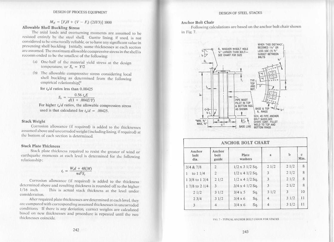
DESIGN OF PROCESS EQUIPMENT
ME = IFF + (v _ F) (2Ht3\) 1000
Allowable Shell Buckling $tressThc axial loads and overturning moments are assumed to be
rcsisted entircly by the steel shell Gunite lining if used is norconsidered to bc structurally reliablq or to have any significant value inprcventing shell buckling Initially, some thicknesses at each sectionarc assumed The maximum allowable compressive stress in theshellrsrlrcomn,cnded to be rhe smallest of the following:
(a) One-half of the material yield stress at the desisnI'-'mpcralurc, or S.: Y/2
(b) Thc allowablc compressive stress considerins localshcll buckling as dercrmined from rhe followinsempirical relationshiplo
for t"/d ratios less than 0.00425
s.= 0.56 t"Ed(r + .oa4E/Y
For higher r"/d ratios, the allowable compression stressused is that calculated for t"ltl : .00425.
Stack WeightCorrosion allowance (if required) is added to the thicknesses
zrssumed above and uncorroded weight (including lining ifrequired) arthc botlom of each section is determined
Stack Plate ThicknessStack plate thickncss requircd to resist the greater of wind or
carlhquakc moments at each level is determined for the followingrclationship:
Corrosion allowance (if required) is added to the thicknessdctcrrrincd above and resulting thickness is rounded off to the hieherl/16 inch. This is actual srack rhickness al rhe level u;derconsidcration.
After required plate thicknesses are determined at each level theyarc comparcd with corresponding assumed lhicknesses in uncorrodedcondilions. If therc is any deviatioq correct weighls are calculatedbltsed on ncw thicknesses and procedure is repeated until the twothickncsscs coincide.
242243
DESIGN OF S]EEL STACKS
Anchor Bolt ChalrFollowing calculations are based on the anchor bolt chair shown
in Fig 7.
\
N.. WASHEB WiSOLT HOLE
Y." LARGER THAN 8011-SEE CHART fOR SIZE
WHEN THIS OISTANCI:
EECoMES 1t/!" 0R
IESS USE (1) {"CUSSET OETWEEI{SOLTS
L"
[,tusrPILOT IN TOP
' TYP.TOPAi{0BOT.
8AS€ LI E
E SOTTOM
As SHO' N
IBASE & TO
n . RTNGS
40 P|PE AIOToRSOLT GUIDE.SEECHART CONT. FILLE]W€LD TO TOP A}IO80TT0M RI.IGS
ITI(;. 7 , ryPICAL ANCHOR BOLT CHAIR FOR STACKS
ANCHOR BOLT CHART
Anchorboltdia.
Anchorboltguide
Platewash€rs
a bMin.
314 &718
1 tolli4| 318 ro 1 314
| 718 to 2 114
2 r12
2 314
3
2
2
2
3
r12
112
112
J
5
4
1l2x3112Sq.
ll2x 4 ll2 Sq.
1l2x4112Sq.
3l4x4ll2Sq.314 x 5 Sq.
314 x 6 Sq.
314x6 Sq.
2
J
3
3
3
4
r12
r12
4
) | l)1 t l)) 111
) tl)
3
1tl)
8
8
8
8
10
llll
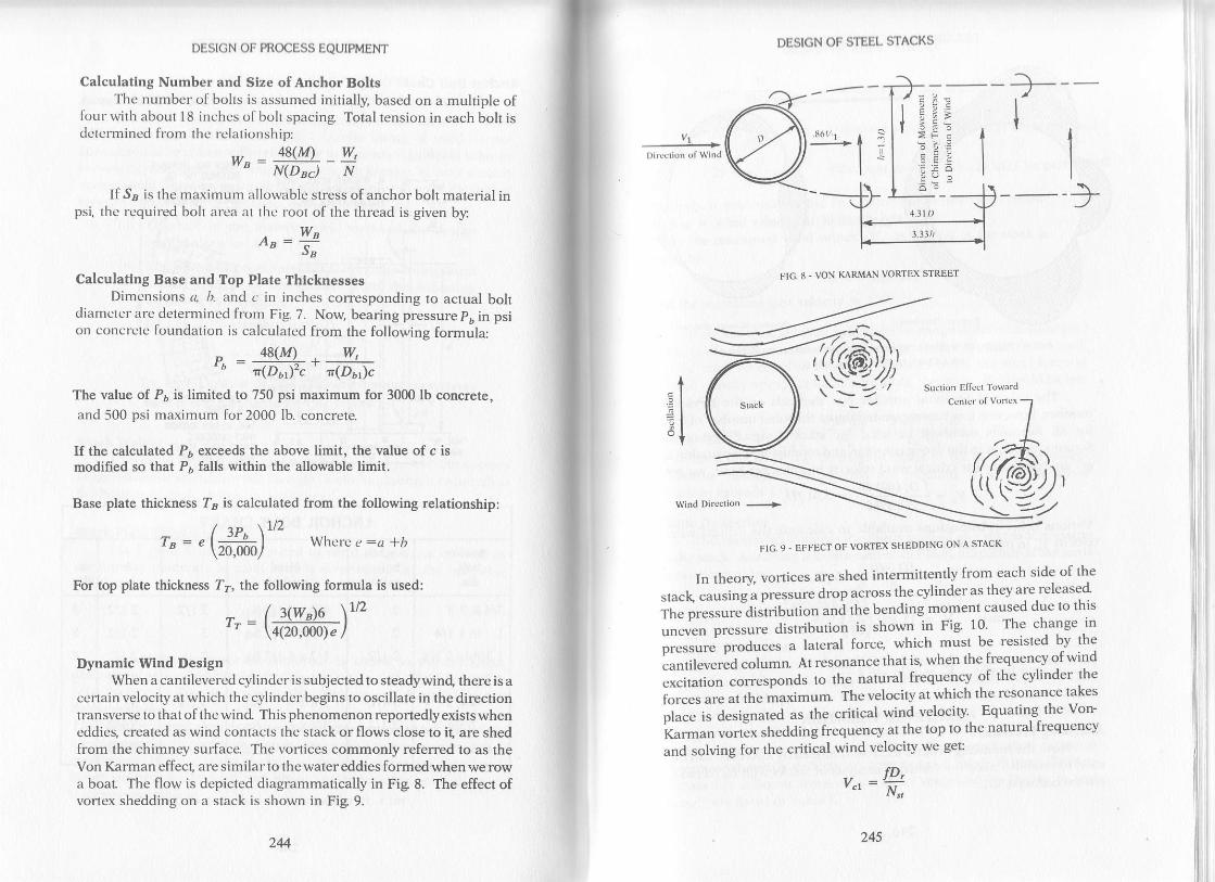
DESIGN OF STEEL STACKSDESIGN OF PROCESS EQUIPMENT
Calculating Number and Size of Anchor BoltsThe number o[ bohs is assumed initially, based on a multiple of
lbur with about 18 inches o[ bolt spacing Total tension in each bolt isdctcrmined from the relationship:
48(M) wttya :
-
_ -' N(DEd N
If SB is the maximum allowable stress of anchor bolt material inpsi, lhc rcquired boh arczr .r1 lhe root of the thread is given b5r
o^ =Y!sd
Calculating Base and Top Plate ThicknessesDimcnsions tt b. and c, in inches corresponding to actual bolt
diamclcr arc dctermincd from Fig 7. Now, bearing pressure pb in psion concrcte foundalion is calculated from the follov.ing formula:
_ 48(m W,
" r(D61)'c r(D6l1c
The value of P, is limited to 750 psi maximum for 3000 lb concrete
and 500 psi maximum for 2000 lb. concrete.
If the calculated Pb exceeds the above limit, the value of c ismodified so that P6 falls within the allowable limit.
Base plate thickness f, is calculated from the following relationship:
/ ap \126 | J'b It" = " \,ffi) whcre , :cr *b
For top plate thickness ?a, the following formula is used:
- | t(w")o \rtz,': \4(2oJoo)r/
Dynamic Wlnd DesignWhen a cantilevercd cylindcr is subjecled to steadywind there is a
ccnain velocity al which the cylindcr begins to oscillale in the directionlransverse to that of the wind This phenomenon reportedly exists wheneddies, created as wind contacls thc stack or flows close to it, are shedfrom the chimney sulface. Thc vortices commonly referred to as theVon Karman effecl, are similarlo thr: watereddies formed when we rowa boar The flow is depicted diagrammatically in Fig 8. The effect ofvonex shedding on a stack is shown in Fig 9.
FIG' 9 - EFFECT OF VORTEX SHEDDINC ON A STACK
In theory vortices are shed inlermittently from each side of the
atu"L, ""l,"ing; pr"ssure drop across the cylinder as they are.released
i"n" p."t""i""Jr.',ttbution ani the bending momenl caused due to this
r.-,n".I* p."t""." distribution is shown in Fig 10' The change in
;;;;;"'p;;t""s a lateral force, which must be resisted bv the
cantilevered columrl At resonance that ig when the frequency of wind
;;.il; lorr".pond" 1o the natural frequency of the cvlinder the
io*"t .tl .attt. -aximum The velocity a1 which the resonance takes
ot.." i" d""ienur"d as the critical wind velocity Equating the Von-
L"r-un uorrit ,hedding frequency at the top lo the nalural frequency
and solving for the critical wind velocity we get:
Q---a
.:
'." =*l
FIG. 8 ' VON KARMAN VORTEX STREET
I+lAI-n
I
fD-
Sucrion Effccr Tolva.d
'*'*'*''*7
@i'
244 245

Bending Mom.nl DiagEm
FIC. IO PRESSURE DISTRIBUIION AND BENDINC MOMENI DIACRAMFOR A STACK DUE TO MDIAL WIND
The value of Strouhal number N,, depends on the Reynoldsnumber, however, il is recommended that a Strouhal number of 0.20for all Relnolds numbers be used for stack design plugging forStrouhal number in the above equation and modifying the equation 10get an expression for critical wind velocity in miles per houl we get
v _ f p. (ffi) 60 = 3.47 tD-'" - .213\7760
Various orher relationships available to calculate the critical windvclocity Yl in mph, are as followsT:
also
and finally V" =
DESIGN OF PROCESS TQUIPMENT
,, fD,(60)," = --fr-
",^(*)' '
'..,t JE (*)
CAI\MLEVER VIBRATIONAnalyzing Procedure
Now, the following criteria as recommended by Zorrilla 1r can beuscd to establish need for vibration analysis of sracks wi th H^ /H rationot cxcecdins 0.50;
246 247
Analysig if required, should be carried out as described below
If, lao = Wind velocity at 30 feet height' mph
itr"n irt. maxim,lm r'ind velocity y-' at the 1op of lhe slack is
given byV* = Vzo(Lt3D)o
to'
and the maximum gust velocity = 1'3V.
Ifcritical wind velocity, % falls within range ofthe maximum gusl
u"to"lty,-th" rtu"t -ust bec'he&ed further' In that case' corroded stack
*"ighi -"* be equal to or greater than 15 times the wind force at
.riii.ut u"to"itv ot ""p."s."d
u" a fot-ul4 the ratio' Kt should be less
than 1/15.
DESIGN OF STEEL STACKS
w20 = h
Vibraliun analvsis MUST be performcd
,to < W - < 25 Vibration analvsis SHoULD be performedHD,'
w25 <
V-OzVibration analvsis NEED NOT be performea'
K, = .vv'-"
For lined slacks l4l can be used in place of W" in order to reduce
vibralion. Design modifications are required if K1. in the above
cquation exceeds 1,/15.
Static DeflectionThe computed d)'namic loading is applied as a slagnant pressure
1o the stack Assuming it to be a cantileverbeam, amplitude at the 1op is
approximated by,
D" _ P"D,LL;(LD3 , where Iz : rr3t
Dynamic DeflectionAl a critical wind velociry the structure vibrates at resonant
f."q,r.'n.v, ^tti
rU"s the amplitud'e ofvibration is magnified greatly' The
auri.-i.1o"ffi"i"nt, which is a ratio of dynamic amplitude to static
^'-of iaa", lt
"Af"d the magnification factor' This is a function of the
iitil" tirir.*". of the soil -and
several other factors' The amount of
ri"tlJa.n"oio" must be multiplied by the magnific^ation factor to
determine dlnamic deflection Approximate value-ot magmncanon
a.i".t i". iirf.*nt types of stacks as suggesred by DeGheno and
Longr2 are listed in Table l.
P,p,L. _ O.\Ulp,s E

DESIGN OF PROCESS EQUIPMENT
TABLE I - MAGNIFICATION FACTORS
fiPE OF STACK
SPREAD FOOTINGSON SOFT SOIL(BEARING BELOW!.500 psl)
SPREAD FOOTINC ON
MEDIUM SOFT SOIL(BEARINC BETWEEN
Li00 rnd 3,000 psl)
PILED FOUNDATIONS
AND SPREAD FOOTINCS
ON STIFF SOILAND ROCK
l0
30
90
Maximum Allowable DeflectlonMaximum dcflection at the top of the stack should not exceed six
inches per 100 feet of stack height
Darnplng Excesslve VlbratlonThe following methods of modiS'ing design are recommended if
an cxcessive amplitude of vibration is expected:
1. External atlachmenls (such as piping ladders andplatforms) may be properly distributed around thestn.rcture which helps to reduce or nullifu the effect ofpcriodic eddy shedding
2. Refractory lining may be added to an unlinedstmcture or the thickness or density of refractory of alined structure increased which adds to the mass andconsequently increases the structural damping
3. If possible, modifying the dimensions of the structurecan also help in damping by increasing the criticalwind velocity above the maximum gust velocity.
4. The paltern of vortex shedding can be modified bywinding helical strakes around the perimeter of theshell at a pitch of about five times the diameter of thechimney. The height of rhe strake should be abouronetenlh of the diameterand manvtimes, strakes areonly required around the top one third of the slackr3A patented device of this t5,pet't has been successfullyused on stmclures to avoid the formation of vorticesand thus cxcessive vibration.
248249
DESIGN OF STEEL STACKS
Ovalllng VlbratlonIn addition t<.r transvcrsc (cantilever) vibration' unlincd stacks are
^frr li,-,Ui..i"a tt ncxural vibration in the planc of the ring as a result of
""ra"* ,n"aai.g Thc frequcncy of rhe lowesl-mode, of flexural
"ib.^ti,rn that oiovalling orbreathing for an unlined circular steel shell
"' , .5gr, J-"tt - 6OD2
Now lhc voncx shedding frequency is given by
, - 0'2vrrv- D
where Vr, the wind velocity for vortex shedding is 66 fps as .
;;;;;;& tv bi"t"v and woodruff for most economical and
;;;i;"k design as far is vibration is concerned
notn rn"."i."quencies should be calculated at each level using
the .<-,rrcsponding thickncsses and diameters Becausc voftices form
;i;;,.d"t eitf,er side of thc stack it has been suggested thar the
or,^llin* fi.ou"n.y will bc rwice thar of the vortex shedding frequency'
ii ;;; il J;ii.; /. < 2/" ovalling rings are required al that level
uih"t-it" thc stack is frce from ovalling vibration'"'-- S".tiun modulus of thc rings' whenever required' can be
dctcnnined as follows:*''-' c.iii"ot*i"a velocityV.in fpm,at the section under consideration
,, _ 60f,p'" - 2N,
whcrc N",' the Strouhal number, is 0 2 over a wide range of
Reynolds numbers.No*, rtt" section modulus of stiffeners at section under
.r..li.']."ii."' ".. be found from the formula used by MoodyT
. - (1)(tof 7 v"\z Dz (H,\J-=_s.
Stiffeners having section modulus equal 10 or grealer than S''
shoull bc provided at spacingl{' throughout lhe length of the section
.rna", .ontia"*tlon. if stiffeners are required for more than one
.".ti.". Jiff"*", sizes and spacing should be used for economy' ifpossiblc.
Ahcrnalively, it is recommended3 that for unlined stacks' having
criticai wind vjocity for ovalling vibration of- 60 mph or less
.ir.,r-f"."ntiul sriffening rings should be provided to stiffen the shell
;;;-;h"t raisc the ovalling vibration frequency Stiffening rings
Jesiencd for a uniform external pressure of 1 5 psi using Section VIII'

DESIGN OF PROCESS EQUTPMENT
Division I <-rf thc ASME Codcts rules, arc rccomnlcnclcd to avoid thcoccurence of ovalling vibration due to voncx shcdding
Example ProblemDesign a200-foot high, free standing multilplc-diameter, unlinedSA-285 Grade C stack as shown in Fig I l. Corrosion allowance:1/8 inch. Operating temperature of stack: 400"F.
->l F.--3,.0" BA.
FIG. I I . EXAMPLE PROBLEM FOR SELF.SUPPORIED MULTILPLE DIAMETER STACK
MomentsGeographical location of the stack did not require moment
calculations due to earthquake Total calculaled wind momenls are.
250 251
DESIGN OF STEEL STACKS
(4 basc ol l2-lt. dia scction: 12,046,570 ft-lb(q) basc o[ l0 [t dia seclion:5,818,910 ft-lb@ basc of 6 ft, 8 in. dia- section : 1,088,410 ft-lb
Assuming corroded thicknesses as follows:0.625 in. for 12 ft dia section0.5 in. for lO-ft dia section0.25 in. for 6 ft, 8 in. dia section
Allowable Compresslon Stress12 ft. diameter section
t"ltl : 0.6251L44 : 0.00434 > 0.00425, therefore
= 14,035 psi
Similarl5,, for the 10-ft dia secliont.ld = 0.51120 = 0.004167
S. = 13,761 Psi6 ft., 8-inch. dia. section
t"td = o.25t8o = 0.003125
S. = 1032a psi
Total Uncorroded stack weightsWeighls at each level are calculated by adding the corrosion
allowancc 1<.r lht-'thickncsses assumed above After adding about l5pcrcent of the calculated weight to account for piping plalformgladders, etc., we gel:
W @ basc of l2-ft dia section : 178,000 lbW @ base of lO-ft dia section : 86,000 lbl,1l @ base of 6 ft, 8-in. dia- section : 23,000 Ib
Requlred Plate Thlckness12-ft. dia" scction
_ 178,000 (144) + 48 (12,046,570)., ----------------r(r44)2 14,035
= 0.6605 inches > 0.625 inches as assumed.
Thcrcforc, totalthickness:0.6605 40.125:0.7855 inchesoruseI 3/16 inch th ick plate for bottom 8 feet of l2-foot diameter sectionWind momcrrts al 8 fect above bottom of l2-fL section
: I 1,136,950 ft- lbt, : 0.6116 inches
Total thickncss: 0.61l6 + 0.125 :0.7366 inches.Thcrcfon:, 3/4 inch plate is sufficient for rest of l2-foot diametersccllon.
0.56 (0.00425) (27.6) Ltr(1 + 0.004(27.6)1f/30,000)
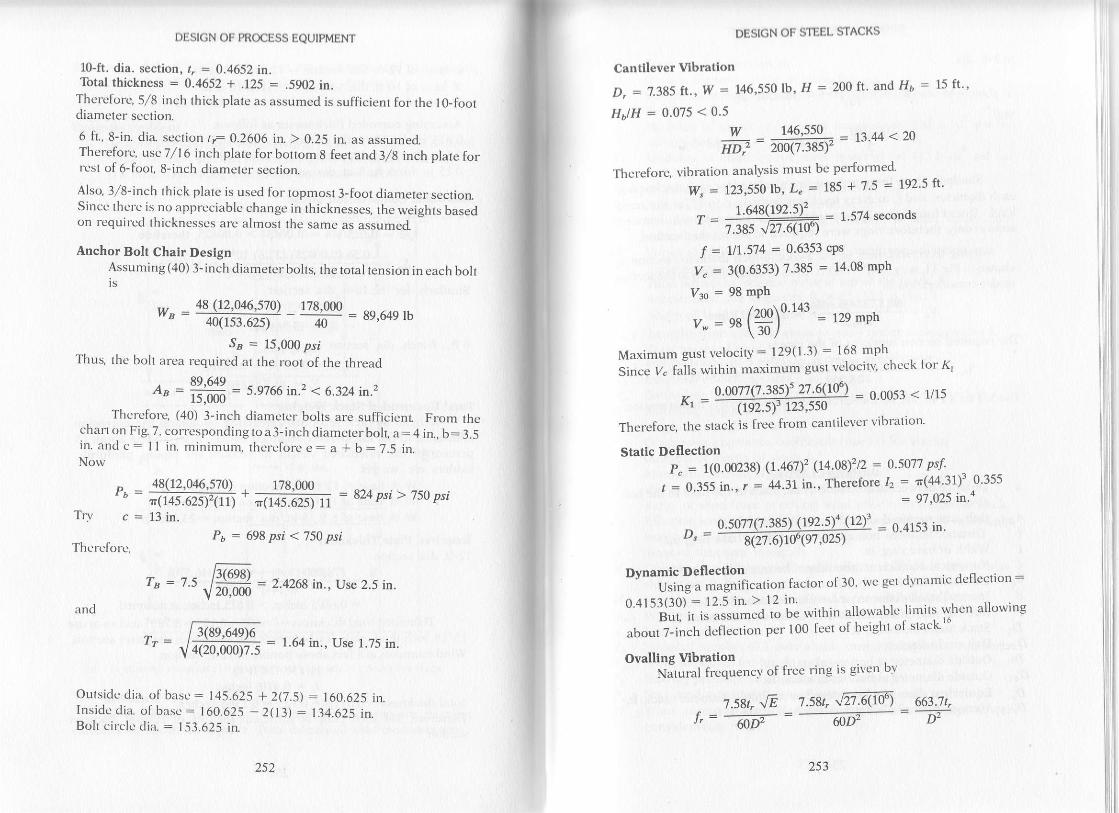
DESIGN OF PROCESS EQUTPMENT
l0-ft. dia. section, r, = 0.4652 in.lbtal thickness = 0.4652 + .L25 = .59O2 in.
Thereforq 5/8 inch thick plate as assumed is sufficient for the l0-foordiameter section.
6 ft, 8-in. dia section tt 0.2606 in. > 0.25 in. as assumed-Thereforc, use 7/16 inch plate for bottom 8 feet and 3,/g inch plate forrcst of 6-fr-rot, 8-inch diameter secrion.
Also, 3/8-inch rhick plate is used for ropmosl3-fool diameter sectiorlSincc ther e is no apprcciable change in thicknesses, the weishts basedon rcquir('d thicknesscs arc'almosl Ihc samc as assumed
Anchor Bolt Chair DesignAssuming (40) 3-inch diameter bolts, the total tension in each boltts
w_ = 48,\1,?'0a7.,s7!l _ 178.000
__ Rq 64o rh' 40(1s3.62s\ 40
Sp : 15,000 psiThus, the bolt area required a1 the rool of the thread
89,649= 5.9766 in.2 < 6.324 in.2r5,000
Thcrcfore, (40) 3-inch diamercr bolts are suflicicnt From thechan on Fig. 7, corresponding to a 3-inch diamererboll a:4 in., b: 3.5in. and c: I I in. minimum, lhcrclore e: a * b: 7.5 in.Now
Trv
48(72,046,570) 178,000
Al456r5irrj * .rr+s^exl rr = 824 psi > 750 psi
13 in.P6 : 698 psi < 750 psi
Thcrcfo rc,
and
- fu(8ri49)6
": Vq-rqoooli= = 1 64 in ' Use l'75 in'
Outsidc dia. of basc : t45.625 + 2(7 .5\ : 160.625 in.Insidc dia of basc: 160.625 - 203) : 134.625 in.B<.rlt circlc din. : l -53.625 in.
252 253
Cantllever Vlbratlon
D, = 1.385 fr., W =
H6lH = 0.075 <0.5
DESTGN OF STEEL STACKS
146,550 lb, H = 200 ft. and lla = 15 ft''
Thcrefore, vibration analysis must be per{ormed'
Iry, : 123,550 lb' L" = 185 + 't '5 -- 192'5 lt'
T- L.648(192.5F - = 1.5?4 seconds' 7.385 v27.6(lo)
f : 117'574 = 0'6353 cPs
V" = 3(0'6353) 7'385 : 14'08 mph
Vgo = 98 mPh
/rnn\0.143 = 129 mphv- = e8l'+*l\JUl
Maximum gusr velocity : 129(1 3) : 168 mph
Since y" fails within maximum gusl velocilv' chcck tor K'
-. 0.00?7(7.38s)'21!09) - 0.0053 < t/t5K' = --nm]Fif-l,so- -'Therefore, the stack is frec from canlilever vibration'
Static DeflectlonP" = t(0.00238) (1.467y (14.0s)'zi2 : 0'5017 psl , ^ ---
r = 0.355 in, r : 44'3lin' Therefore I: : n('l4 3l)' O 355
= 97 '025
in''
w _ 146,550 _ = t3.44<20HD: 200(7.38sr
= 0.4153 in.D":
Dvnamic Deflection""*i:il;;;niii"ttion factor of 30' we ge1 dvn;rmic deflection -0.4153(30) : 12 5 in. ).12 in'
BuL il is assumed lo oe wtthin allowable li:nits when allowing
aboul 7-inch d.'flection per 100 fect o[ hcight ul stacr
Ovalllng VibrationNJtural frequency of free ring is given by
1.su,\E t.su,Jn@ 6$.11i=--ffi-=----1y,F-: D-
o.su| e.3ss) (|w.r't (nfaQ1.qrffgl,ozs)
al 3-li. dia.,
and
DESIGN OF PROCESS EQUIPMENT
= 18.4361 cps
= 4.4 cps,2f" : 8.8 cps < f,
Use 5/8 in. x 2-in. flat bars as circumferential stiffeners in this sectioIL
Similarlv, thcse frequencies were calculated foreach thickness areach diamctcr; and/, at cvery level was compared 10 2te al the samelcvcl. It was found thar 21, excceds rhe t al 6-fool g_inch diamerersection only, thcrcfore rings were required to stiffen thal section.
Using threc sliffeners in the 6-foot, g_inch diameter sectiorr asshown in Fig I 1, wc get fl, : I 7.5 ft Criricalwind velocity at the sectionunder considcration is
v" _ @(3.7J14)9.6666 = 3733.3627 fpn- 2(0.2\
Thc required section modulus of the rine is
s_ - 0)$0f '(3733.{4):6.666)'z1'7.s = 0.4158 in.3-' lR rSn
" 0.2(66\"-
-3
ABb
NOMENCI.ATTJREDistance between the oulside of the stack at the base to the boltcircle inBolt area required at the root of the thread in.2Distance between bolt circle to outside of base ring in
Width of base ring inNumerical coefficient (should not be more than 0.12)Lift coelficienr (usually nken as 1.0)Internal stack diameter at level under consideration, inInlemal stack diameter at level under consideration ftStack mean diametel ftBolt circle diameler, in.Outside diameter at bottom of stack fLOulside diameter at bottom of stack iILEquivalent diameter for rapered or multilple diameter snck ftAverage internal diameter of top half of stack ft
ZcrdDDr
DacDt'
Dot
D.Dl
254 255
DESICN OF STEEL STACKS
D. Slalic stack dcllcclit.rrt, it.t.
Dt Oulsidc diamctct' a1 lop ol slzrck li.
l Distancc bctwccn thc outside of the stack a1 thc basc to outside of
material, psi (30 x 106 psi for
material psf (43.2 10" psf forEL
E2
f,FF
It
lhc ring in.
Modulus of clasticiry for stackcarbon steel)Modulus of clasticity for stackcarbon slccl)Modulus of elasticity for lining material, psf.
Natural frequ.'ncy o[ slack vibralion.cpsNalural frcquency of ovalling vibration at level under con-
sideraliqn, cpsVortex shedding frequency al levcl under consideration, cps
Force on slructurc', lbTotal horizontal seismic force al lop of the slack lbAcccleration due to gravity, ft/ scc.'z (32.2 h/sec.'\Width of Von Karman Slrcel fLLenglhs from centroid areas to point under consideration, fL
Total height of stac( fiHcight zoneg ftHeight of conical section(s) of stack ftEquivalcnt height for tapered or multiple diameter stack ftStiffening ring spacing ft.
Height of slraight section(s) of stack ftOccupancy imprtance coefficient (use l 0 for stacks)
Moment of inertia of stack ftaMoment of inertia of lop half of stac( in"Horizontal force factor (use 2.0 for stacks)
Ratio of wind force al crilical wind velocity to weight of stackEffective lengh of stack ft (can be assumed equal 10 straightlengrh plus onehalf of conical length)Mass of struclure, Ib-secr/ft-Grealer of wind or eanhquake moment a1 level under con-
ht,.,zH
Ht,z,zHbH.HH"1
I1t2KK1
ntM
sideration, ft-lb.Ms Eafthquake moment at level under consideration, ft-lhM- Wind moment at level under consideration" fr-lb.N Number of boltsN,, Strouhal number (0.2 over a wide range of Reynolds number)Pr,z,e Wind pressures for height zoneq psfPb Bearing pressure on concrete foundation, psiP. Unit wind pressure al critical wind velocity, psfPF1,2 Wind moment due to individual platform at level under
consideratiorl ft-lb.

r\s,tss"
DESIGN OF PROCESS EQUIPMENT
Average internal radius ot top half of stac( inStack mean radius, ftNumerical coefficient for site structure resonanceMaximum allowable stress of anchor boh material psiAllowable compression stress in plate material at level underconsroerauon, psr
S- Required section modulus of stiffeners, in.3
.Srr Allowable tensile stress of stack plate material psit Average corroded plate thickness of top half of stacl in.tr Stack plate uncorroded thickness, fLto, Assumed corroded plate thickness al level under consideratiort
in.t6 Uncorroded plate thickness at bottom of stack, in.I, Required corroded plate thickness at level under consideratiorL
in.T Fundamental period of vibratio4 secondsTB Base plate thickness, in.T7 Top plate thickresq iny Total seismic shear at base of stack lb.Vr Wind velocity for vortex shedding fps73e Wind velocity at 30 fee! mph% Critical wind velocity for cantilever vibratiorl mphY"1 Critical wind velocity for cantilever vibration, fpsV" Critical wind velocity for ovalling at level under consideratiorl
fpmV. Maximum wind velocity at the top of stach mphw Stack weight per ft of height lb./ft.w1 2 Weight of individual section of stack lb.W Total corroded stack weight including lining lb.Wr Total operating weight of stach kipsWp Total tension in each boll lb.
W" Corroded weight of shck excluding weight ofpans which do notcontribute to stiffness, lb
Wt Total uncorroded stack weight, lb..rr.2 Dead load deflection of individual section of stack ftI Yield stress of plate material at design temperature, psiZ llBC seismic faclorP Mass density o[ air (0.00238 lb-sec']/fra)to Circular frequency of stack vibratiorl cps). Stiffness of structure. lb.,/frA Deflection of structure, ft
256
14.
DESIGN OF STEEL STACKS
3.
l.
'1.
9.
13.
lt.
t2.
REFERENCES
"Minimum design loads in buildings and other str-uctures," ANSI
A58.1, 1982."Uniform building code," International Conference of Building
Officials, Whittier, California 1982.
Stalev, C.M. and Graven, G G, "The static and dynamic wind design
of steel sracks,"ASME Paper No. 72-Pet-30.
Frecse, C.E., "Vibration o[ vertical prcssure vesselq" Journal of
Engineering for Industry Series B, Trans ASME Vol 81' No l'Fcbnrary 1959, pp. 77-86.Gaylord, 8.H., Gaylord, C.N, "structural Engineering Handboo("McGraw-Hill Book ComPanY, 1 968.
Dickey, WL and Woodruff G.8., "The Vibration of Steel Stacks,"
Procccdings of the American Society of Civil Engineers, VoL 80,
Scparale No 540, Nov 1954
Moody, G.B., "Mechanical design of rall stacks," Hydrocarbon
Processing 48, No 9, September 1969, pp, 173-178'
Marrone, A. "Vibrations of slacks suported on steel structures,"
Proceedings of the ASCE Vol 95, No. ST12, December 1969, pp'
283t-2844.Parmaleg RA, " Buildingfoundation interaction effects," Proceedings of the ASCE VoL 93, NO. EM2, April 1967, pp 131-152'
-
Donncl-L LH., "Results of experiments with very thin cylindrical
shells under axial pressure," Transactions of the ASME Vol 56,
1934.Zorrill4 E.P., " Determination of aerodynamic behavior of can-
tilevered stacks and towers of circular cross sec1ion," Transactions
of ASME, Paper No. 71-Pel35Dechetto, K, and Long W' " Dlnamic stability design of stacks and
towers," Journal of Engineering for Industry Series B, Trans ASME,
Vol 88, 1966, p 462."British Standard Specifications for Steel Chimnels," B S' 4076:
1966, British Standard Institution, British Standards House, 2 Park
Streel London, Wl.Scruton, C. "Note on a device for the suppression of the vorterexcited oscillations o[ flexible structures of circular or near-circulal
section with special reference ro its application to tall stacks "National Physical Laboratory Teddington, Middlesex, England'
Aero Note 1012, APril 1963.
10.
DESIGN OF PROCESS EQUIPMENT
15. ASME Boiler and Pressure Vessel Code, Seclion VIII, .,pressure
vesselg" Division l, ASME New York N.y. 1983.16 Tang S.S., "Shortcut method for calculating tower deflectio4,'
Hydrocarbon Processing 47, No. ll, November 196g. rl. 230.
Wintl inducBd vortices ale formed on the surface of tall structures
such as heater stacks and plocess towe$. The change in pressure associated
with shedding of these vortices can generate forces required to proiluce
instability an-<l can'even result in structural failures' Thus, after the self-
suppoiting structure has been designed as a static structwe, it must also be
i"vestlgated regaraling its possible behavior under vibration conditions'
ihis chapter extends Zorrila'sl method by establishing simplified
relationships from his data. It also presents some of his graphical data in
tabular form for quick vibration inv€stigations of self-supporting vertical
cylindrical, cantilevered structures such as towers and stacks' Criteria' as
recommenied by Zorrila, is used to estiblish a need for such analysis' Ifthe structure is foun<t to be susceptible to vibmtion, the amPlitude of
vibration (maximum dynamic deflection at top of the structure) can also
be easily determined. Methods of ilamping excessive vibmtion are recom-
mentled-. .l sample calculation is included to demonstrate the use and
accuracy of the technique presenteal.
Analvzing procedure.lnat-yiing aU ttre towers and stacls in a plant or refinery for vibmtion
would be time consuming process. The following criteria is used to investi-
gate vibmtion possibility in a structure:
$ = ,outorurion analysis MUST be performed
20< #< 25 Vibration analysis SHOULD be performerl
12
VIBRATION ANALYSIS OF TALL TOWERS
wffi258
25< Vibration analysis NEED NOT be performed

| )t jsl(;N ()t, t,tr()Chss TjQUtPMENT
Analysis, if required, should be carried out as described below.Natual frequency of vibration. The natural frequency of vibration,
/r, of a bare structure in its fundamental mode for unit uit e ot lOlLzj(10)a can be read from Table 1 corresponding to ,6, the uncorroded thick_ness at the base of the structure_ This table is an extension of a graphicalpresentation by Zontla based on the calculation of natural vibration lie_quencies of several structures bmethod proposed by Major.2
ry a computerized technique using the
_- . Thus, the natural frequency of vibration for a bare structure(Wlll" = 1) based, on actual value of (DlL2) (tO)a is given bff = (ft) (D lL2) (1o)4
_
lvhen refractory linings, insulation, ladders, piping, platforms, in_te-rnal trays, operating liquids, etc. are considered to iontribuie to stiffnessof.skucture (l|lws > 1), the frequency of yibration will be reduced con_$oerably. tn that case, determine the correction factor CF, correspondingto the ntioll/Wsfrom Table 2. Intermediate values should- be interiolated.The natural frequency of vibration is given by
f = (ft) (D lL2) (10)a (c F)
_ Logarithmic decrement, 6 is the log of the mtio of successive ampli-
tudes of a damped, freely vibrating structure and i, " mearur" of the
structural ability of the stack or tower to dissipate energy during vibration.For a particular structure 6 depends on ih" typ. oi
"onrtr"u"tion "nathe lining used. The value of6 can be selected fromiable 3 as recommenO_ed, by-Zorrila based on the reported average values of several ,t*atur"r.- Stability investigation. The wind tunnel test3 shows the O.p"ni.n."
of oscillations on structural damping. Further staUitity lnvestigitions forstructures can be made as follows:
Calculate the damping factor Dp from the relationship
Or=#A check for stability can be made according to the following criteria
proposed by Zorrila on the basis ofactual behavior of several case-historiesconsid€red: Dp,3 0.75 unstable
0.75 <DF < 0.95 probably unstable
0.95 <DF StableIf, the structure is not found to be stable, calculate the critical wind
velocity from
tt" = 3 f D,
260
VIIJRATION ANALVSIS oF TALI, 'TOWERS
TABLE l-Frequency of bare structures for unitvalue of (D/L2) (r0)4
tr,Thickness, in. fi, Frequency, cps
0.250.31250.3 7so.43'7s0.5o.5625o.62so.68'7 s0.750.81250.8750.93',7 5
1.0
0.37 5
o.4Q269.42840.4440.4642o.474o.482r0.4940.50.5120.5230.5330.5 5
TABLE 2-Correction factor for frequency
Ratio of weights I//It4 Correction faclor Cp
1.01.12st.25|.3',7 5
t_)1, .7 5
2.O
2.53.03.54.O
4.55.05.56.0
l_00.90.850.8o.790.'1350.690.60.5 5
0.50.465Q.435o.40.3 85
o.37
261
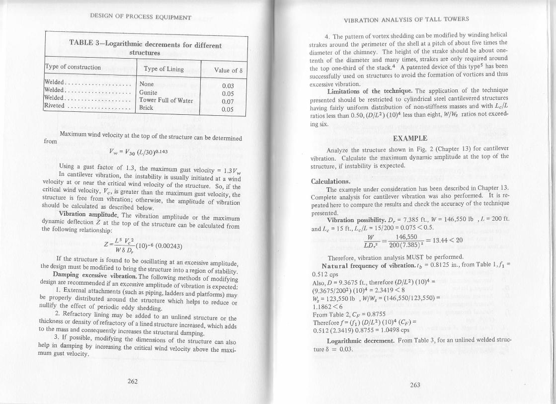
l)l1st(;N ( )ti I'l(( x:tlSS Ij(ltJ ,MtrN.tvll!l{Afl()N ANAI.YSIS ()l: lAt.l. lowlilts
4.'llrc prttcrn ol'vortcxslrcddirlS canbe modit'iod by winding lrelicrl
strakes around thc perimeter of the shell at a pitch of about five times the
diarnoter of the chimney. The height of the strake should be about one-
teoth of the diameter and many times, strakes are only required around
the top one-third of the stack.4 A patented device of this types has-been
,u""arifully used on structures to avoid the formation of vortices and thus
cxcessive vibration.Limitations of the technique. The application of the technique
presented should be restdcted to cylindrical steel cantilevered structures
lraving fairly uniform distribution of non-stiffness masses and wrtn L"lLratios less than 0.50 ,(DlL2) (lO)4less than eight, Illl/s ratios not exceed-
lng srx.
EXAMPLE
Analyze the stuucture shown in Fig. 2 (Chapter 13) for cantilever
vibration. Calculate the maximum dynamic amplitude at the top of the
structure, if instability is expected.
Calculations.The example under consideration has been described in Chapter 13'
Complete analysis for cantilever vibration was also performed- It is re-
peatedhere to compare the results and check the accuracy of the technique
presented.vibration possibility. D, = 7.385 ft' w = 146,550 Ib, L = 2oQ fr'
and.L" = l5 ft., L"lL = I 5/200 = 0.075 < 0.s.
w _ 146,550 - ta LL z. nnLD.' = zoo0.385Y - rJ -rr \ 4u
Therefore, vibration analysis MUST be performed.
Natural frequency of vibration. 16 = 0.8125 in , from Table l,11 =
0.512 cps
Also,D = 9.36?5 ft., therefore (Dp2) (10)a =(9.367 sl20o2) (r})a = 2.34t9 18tlls = 123,s50 lb ,Wlll"= (146,5501123,5s0) =
|.1862 < 6
From Table 2,C" = 9.9155Therefore / = (f1) (D lL2) (r])a (.Cp) =0.512 (2.3419) 0.87ss = 1.0498 cPs
Logarithmic decr€ment. From Table 3, for an unlined welded struc-
ture 6 = 0.03-
" Maxim[m wind velocity at the top of the sfuucture can be determmedtrom
V* = V3o (Ll3o)o.r43
Using a gust factor of l_3, the- maximum gust velocity = l.3ll,. .In cantilever yibration, the instability is usuitty inifiaiei at a winOvelocity at or near the cdtical wind u"to"ity of tne-itru","* ,", O,r,.cdtical wind
^yelocity, Zc, is greater than the maximum g"r,
"af""ny,,nar,rru..,lt" it free from vibration; otherwise, the amphtlude of villtronshould be calculated as described below.
. Vbration amplitude. The vibration amplitude or the maxinumdynamic deflection Z at the top of tne ,tru"tur" ""n
t""..i."f ",fr"fr".the following relationship;
):t'"'w 6 D-00)-6
(o oo243)
If the structure is found to lthe desisn musr be m";r,J;"- ;;#.;:",',1l.jil1J:;: :-fi lll""iT,r",,lil,;.Damping excessive vibration..ff," foffo,oing rn"ih;;r';f;ffi;,r,design are recommended if an excessive ,.plit"d;; ;;;;;", ir'"_#"a,, t. External attachmenrs (such as piping,ladd"J;;;;j;,;;;:;;"ybe__properly distributed around the structure which t.,"fp, to ,"0,i". _nulJify the effect of periodic eddy shedding.
.,. . z. Ketractory lining may be added to an unlined structure or thethickness or density of refractory of a lin"d,trr"t; i;;;;;, ;;;*,to lhe-mass and consequently increases the structural damping.
, . .r. ]t possible, modifying the dimensions or ir.. -,iu.?ur"
._ urroh€lp in damping by increasing the cdtical wind verocity auou" tr,e ml*imum gust velocity.
zoz263
I )tis t(;N ()tr pt(()cLSS DQUtPMENT
Stability investigation. The damping factor DF is
n _ w6 _ 146,550t0 n?)u" = TL, = =ffiffi = 0.4031 < 0.75
Therefore, the structure is unstable.The critical wind velocity is
Vc = 3 fL = 3(1 .0498) 7 .38s = 23 .2583 mphZ3s = 98 mph
vu, = ho (Ll3o)o.143 = 98(200/30)0.143 = 129 mphMaximum gust velocity = 1.3(129) = 168 Inpil
_ Since I/" ( maximum gust velocity, the dynamic amplitude must bedetermined.
Amplitude of vibration. The maximum dynamic deflection isf 5l/ 2L= Wt(l0fo (0.00243)
_ (200 ) " (23.2583 ) '( l0 )-6 (0.00243 )- 146-;5so-(oo-tiis-t- = Izeb rn'
which is within allowable limits if 7in. deflection/IO0 ft. of structureheight is allowed.
Comparison of results. There is an appreciable difference in naturalfrequency of vibration and thus the critical wind velocity as compared tothe earlier method. However, the dynamic deflection of 12.96 in. seemsto be reasonably accurale as compared to I2.5 in. calculaled earlier,
tt may be concluded that this technique is quite accurate and muchless time consuming when compared to other conventional methods.
NOMENCLATURECorrection factor for frequencyAverage internal diameter of structure, ft.Damping factorAyerage internal diameter of top half of structure, ft.Natural frequency of vibration of strucrure, cpsNatural frequency of bare structure based on unit vafue of (DlL2)(10)4, cps
DD-D,
Z Total length of structure, ft.Lc Total length of conical section(s) of structure. ft.t6 Uncorroded plate thickness at the bottom of structure. in.I/rs Wind velocity al jO feet, mph
264 26s
VII}I{ATION ANALYSIS oI;'I'ALI,'I'OWljI{S
V. Critical wind velocity, mPh
,/1, Maximum wind velocity at th€ top of structure, mph
l,/ Total corroded weight of structure, lb
Ws Corroded $,eight of structure excluding weight ofparts whlch do no1
contribute to stiffness, lbZ Maximum amplitude of vibration at the top ofstructure, in.
6 Logarithmicdecrement
REFERENCES
l. Zorrita. E. P.. "Determination of Aerodynamic Behavior of Cantilevered
Stacks and Towers of Circular Cross Section," Transactions of ASME
Paper No. 71-Pet-35.2. Major, A., "Vibration Analysis and Design of Foundations for Machines
and Turbines," Collet's Holdings Ltd., London, and Akaddmiai Kiadd,
Budapest, 1962.3. Scruton, C., "Wind Effects on Structures," Proceedings of the Institution
of Mechanical Engineers, 1970-?1, Vol. 185 23/71, February 1971.
4. "British Standard Specifications for Steel Chimneys." B. S. 4076: 1966,
British Standard Institution, British Standards House, 2 Park Street,
London, W.1.5.Scruton. C.. "Note on a Device for the Suppression of the Vort€x-Excited
Oscillations of Flexible Structures of Circular or Near{ircular Section
with Special Reference to its Application to Tall Stacks." National
Physical Laboratory, Teddington, Middlesex, England, Aero Note 1012,
Aoril 1963.
dfii 'il-ii" "tigtttty
modified version of author's srudv: Analyze To*er vibration Quicker"ilft"lia-i ny&*itrton Processin1 volume 56. Nb. 5 {May. 1977) Copyrighted Culfitblishing Co. Used with permission.

13
DESIGN OF RECTANGULAR TANKS
The chemical plocess industries use vessels of various shap€s and
sizes to store, accumulate or process gases, liquicls and solids'
While a cylindrical shape may be structurally best for tank construc-
tion, rectangular tanks frequenuy are preferred-even though these require
" laiger quantity of matedal for eonstruction than do cylintlrical tanks of
the same capacity. On occasion, special piocesses or operations may make
cylinclrical tanks imPractical. When several separate cells are needed, rec'
tangular tanks can be easily fabricated and arranged in less space than
cylinrirical ones of the sarne capacity. This is especially helpful when the
tanks or vats are needed insirle a building'We will discuss the complete design technique* fol flat+urfaced
rcctangular tanks that contain nonpressurizeilliquids. These exert a varying
horizontal pressure against the side-walls, as shown in Fig' 1' The walls of
the tank act as plates having suitable edge conditions (i.e', the edges are
free and supported). Such plates are analyzed under certain assumptions
by using the theory of bending for thin plates.2
The data as originally presented by Wojtaszak" in glaPtucd rorm'
and later represented by Roark and Younga in tabular form are used for
analysis. In oriler to apply these data,the following assumptions are made:
(l) iectangular plate has a uniform thickness, (2) allowable deflection ofthe plate is held to within about one half the ptat€ thickness, and (3)
Poisson's ratio for the material is 0.3'To obtain the required rigidity for a lighter€age plate, stiffenen are
recommended. This can lower fabrication cost considerably' A sample
oroblem will show how to use the technique.
*The currcnt Aflsrican Petroleum Institute Standaral fot tank designrdo€s
not include a t€chnlqu€ for snalyzing the rectangular confiSrtation'
267

I )tjst(;N ()lr pllo(:uss IQUtpMtNT
l)esign procedure wil.hout stifreners
_ We begin by calculating the maximum plessure against the side_walldue to the weight of the contents from:
p = 0.433Hs (t)Tanks without stiffeners have their top edge free, and the remaining
three edges supported. Flat-plate formulas can be directly applied for thisedge condition to determine stresses and deflections.
We calculate the ratio afb (that is, the height, a, of the tank to thelarger of the length or width dimension, b), and read the correspondmgvalues of constants B and a from Table 1. Intermediate values should beinteryolated.
The maximum bending stress in the plate is given by:s^"" = ppb2/Q)z
e.)
_ . Stresses as recommended by the ASME Code for pressure vessels5
may be increased_rrhen used for designing tanks under hydrostatic pressure.I he r_nax-imlm allowable working stress is considered to be approximatetyone third of the ultimate tensile strength of the steel. (This is a factor ofsafety of 3, which is also common for static structural lo;ds on steel) For:iTqli:ity, a more appropriate value of allowable bending stress, s_*, of18,000 psi for plates and stiffeners is recommended by young.6
. * The. required corroded-plate thickness, tr, can be founJ by rearrarg_ing Eq. (2):
. nPe(3)
FIG. I . PRESSURE DISTRIBUTION IN RECTANGULAR TANK
268 269
DESI(iN OI] RIiCTANCUt,AR TANKS
Ratio, a/b 0.5 0.667 1.0 1 .5 2 o 2,5 3.0 3.5 4.o
Constsnt, p o.'l1 0.16 o.2o o.2A 0.32 0.35 0.36 0.37 O37
constanr, a 0.026 0.033 0.040 o.o5o 0.058 0.0&l 0.067 0.069 0.070
Sourcs: Modlfi.d from Raf.4
TABLE 1. CONSTANTS FOR RECTANGULAR PLATES' SIMPLY SUPPORTED
ALONG I'HREE EDGES
(FREE ALONG TOP EDGE AND SUBJECT TO HYDROSTATIC PRESSURE)
The thickness determined from Eq. (3) should be rounded off to the
next higher sixteenth of an inch, and a cofiosion allo\Mance (if required)
must be added to this value in order to get the minimum required total
plate thickness. However, in no case shall the corroded thickness of tank
plate be less than 3/16 in-Maximum deflection of corroded plate is given by:
Y^". -- aPba/E(t")3 (4)
Maximum plate deflection should be limited to one half of the
corroded-plate thickness. Ifthe final plate thickness seems uneconomical,
or maximum plate deflection exceeds one half of the corroded-plate thick-
ness, a top€dge stiffener shouldbe added, and an analysis for this condition
made.
Design procedure with top-edge stiffenersAll edges of the tank may be considered supported if a top€dge
stiffener ofsufficient size is added. For this type of beam(supported attop
and bottom, and carying a varying load that increases uniformly to one
end), the bending moment at top and bottom edges is zero. However, this
type of loading results in reactions R 1 at the top edge and R 2 at the bottom
edge, as shown in Fig. 2. The magnitudes of these reactions are:
R, = pan/6 (5)
R, = patn/3 (6)
Reaction R1 is assumed to be a uniformly distributed Ioad per unitlength of top edge, and the beam alo4g that direction is considered to be
fixed at both ends. The maximum deflection of the beam? with this
type of loading is given by:
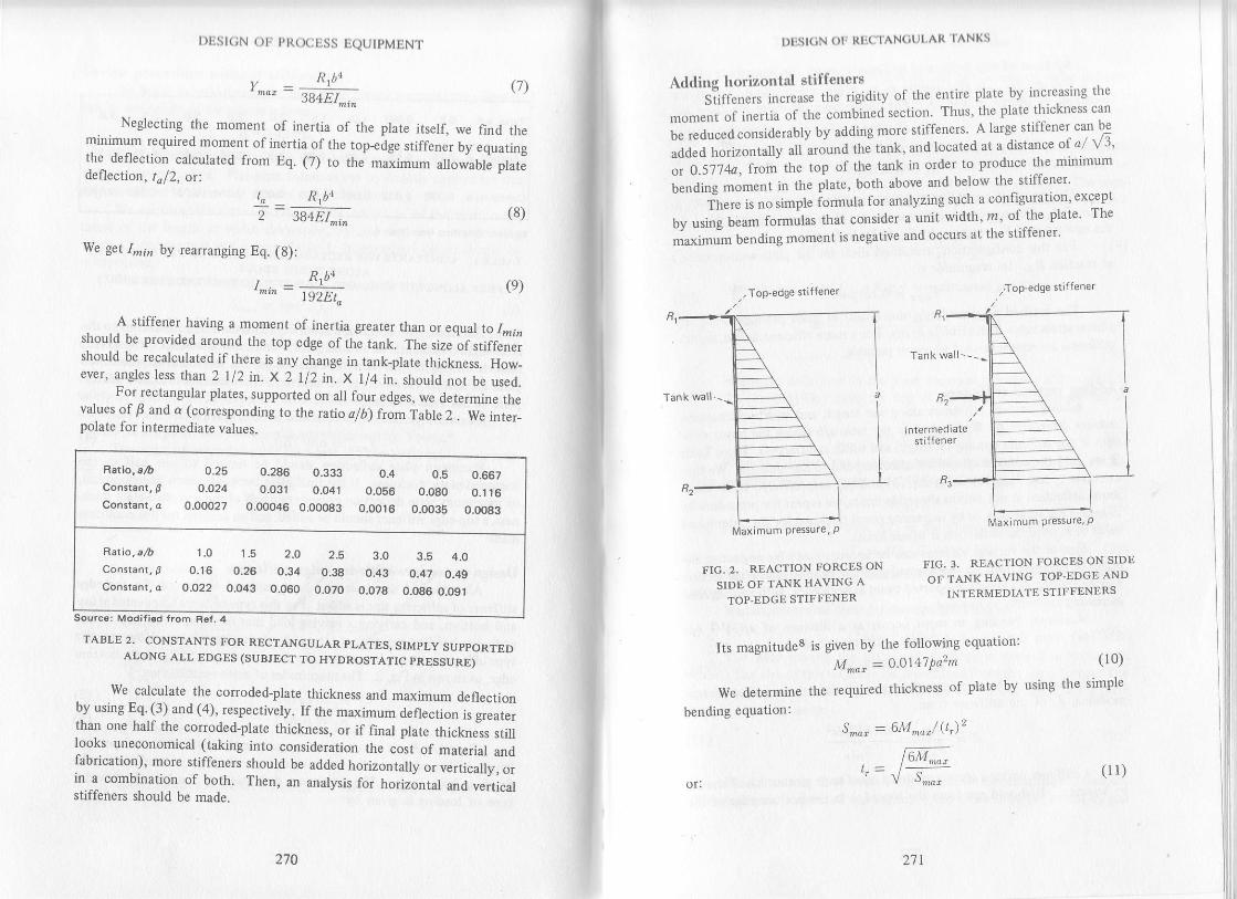
l)Lst(;N oF PR(XlllSS EQUIPMENT
Y^o, = . Rrbn (7)3B4EI^i.
Neglecting the moment of inertia of the plate itseli we find theminimum required moment of inertia of the top_€dge stiffener by equatingthe deflection
-calculated from Eq. (7) to the maximum
"ttowaUte pt"t"
defleclion, taf2, o(to _ Rlba
2 3g+El,'.i, (d'
We get Inin by rearranging Eq. (8):
, R.bntni" = lsrE;.(e)
A stiffener having a moment of inertia greater than or equal to 1,nrnshould be provided around the top edge of the tank. The size of stiffenershould be recalculated if therc is any change in tank_plate thickness. How_ever, angles less than 2 112 il. X 2 112 in. X ll4 in. should not be used.
- Fo-r -rectangular
plates, supported on all four edges. we determlne ttrev,lues of F and a (correspondin g to the ratio sf b) frorn T"bl" Z . We inter-polate for intermediate yalues,
Sourcs: Modifiod from B€f.4
TABLE 2. CONSTANTS FOR RECTANGULAR PLATES, SIMPLY SUPPORTEDALONG ALL EDGES (SUBJECT TO HYDROSTATIC PRESSURE)
- We calculate the corroded_plate thickness and maximum deflectionby using Eq. (3) and (4), respectively. If the maximum deflection is greaterthan one half the corroded-plate thickness, or if final ptutu tti"t,"-"r, ,tttlooks uneconomical (taking into consideration the cost of material anclfabrication), more stiffeners should be added horizontally o, uo,i"uliy, .,in- a combination of both. Then, an analysis for horizontal anO verticafstiffeners should be made.
Rario, ah 0-25 0.286 0.333 0.4 0.5 0.667constanr, B 0.024 0.031 0.041 0.056 O.O8O 0.1t6Constant, a 0.00027 0.00046 O.OOO83 0.0016 O.OO35 O.OO83
Aetio,ah 1.0 1.5 2.O 2.5 3.0 3.5 4.0consrant,, 0.16 0.26 0.34 0.38 0.43 o.47 O,4gConstanr, a O,O22 0-043 0.060 O.OZO 0.078 0.086 0,091
270 2'.1|
(l l)
Dtisl(;N olr Rlic rAN(iul'AR ',TANKS
Adding horizontal stiffeners"*'i?iff"t." ln",.ur. ttt. rigidity of the entire plate by in-creasittg the
momentofirlertiaofthecombinedsectionThus'theplatethlcknesscanl. ,.Ou..O .onriO"rably by adding more stiffeners' A large stiffener can be
added horizontally all around tne taJ, "J f""*O " "
O \statce of.a/ rt'.-OSilii', frorr the top of th€ tank in order to produce the minimum
i"rOint ."rn*, in the plate, both above and below the stiffener'
Tiere is no simple iormula for analyzing such a configuration' €xcept
by using bbam formulas that consider a unit width' m' of the plate The
maximim bending moment is negative and occurs at the stiffener'
lntermedrarestiffener
N4aximum Pressure, P
FIG,2. REACTION FORCES ON FIG' 3' REACTION FORCES ON SIDE
SIDE OF TANKHAVING A OF TANK HAVING TOP-EDGE AND
TOP.EDGE STTFFENER INTERMEDIATE STIFFENERS
Its magnitude8 is given by the following equatlon:
M^a' = O'O]l47Pa2m (10)
We determine the required thickness of plate by using the simple
bending equation:s^M = 6M''",/ (q),
lMaximum Pressure, P

t)tisl(;N ot' PRocEss EQUIPMENT
Addition of this horizontal stiffener changes the magnitude of reac-tions Rl andRz. It also results in an additional reaction, R3, at thislocation, as shown in Fig. 3. The magnitudes of these reactions are:
R, = O.O3}pan
Rz : 0 l5lqamR" = 0.320pan
(12)
(13)
( 14)
(17)
The intermediate stiffener can be sized from Eq. (9) by usingR3 rlplace of Rr. The top+dges stiff€ner can also be resized,if desired, by usingthe newvalue ofRl-as given by Eq. (12) in Eq. (9).
For this configuration, maximum shear on the plate section occursat reaction R3. Its magnitude is:
V*, = 0.l59pab (1s)The method of considering unit-width of ptate produces a slightly
greater stress value than actually exists. For a more efficient design, verticalstiffene$ are recommended wherever possible.
Adding vertical stiffenersAdding vertical stiffeners along the length and width of the tank
reduces dimension b. We recalculate the /ztio afb (using the larger valueof , if the stiffener spacing on length and width is different). From Table2, we find the constantsp and (r that correspond to the ratio a/r. We thencalculate tr a'nd Ymax by using Eq. (3) and (4), respectively. If the maxi-mum deflection is not within allowable limits, we repeat the procedure bychanging the value of b, or by increasing panel thickness for the determinedvalue of r, until the deflection is within limits.
Size of the vertical stiffener can be approximated by neglecting theeffect of the plate itself for the selected stiffener spacing. The plate sectronmay be treated as a simply supported beam at both ends, with varying loadincreasing uniformly to one end.
Maximum bending moment occurs at a distance of al(3)rl2 (or0.5114a) from the top of the tank. Its magnitude is:
M*, = 0.0642qta2 ( 16)
By using the bending equation, we calculate the required sectionmodulus, Z, of the stiffener fromi
- M^", 0.0642p1a2
s,,", s,'",
A stiffener having a section modulus equal to or greater thanZ shouldbe selected. It should run from the top edge to the bottom edge of the
272 2-13
DESICN OII RIJCTANCUI.AR 'fANKS
tNrk. 'l'ltc resultant stilfening eflecl should not bc uscd to resize the toP
r,rlgc stillbner, due to the extreme complexity of this analysis'
lh.rriurr analysis for the tank"' 'Tft" utl'i"f method of analysis is to consider a section of the plate
llrving a width equal to the distance between centers of the stiffeners ln
if,ir rlo"*t, only one stiffener is to be included in the analysis The com-
it,,'.J t..,t"" *iil b" u, shown in Fig' 4' The moment of inertia for this
rcction can be found from:
,_, _ Ar\ta\2 -+
ArAz(hiz12 At+42
Dimensions Cl and C2 in Fig' 4 are calculated as follows:
(1e)
(20)
Maximum deflection in the plate occurs at a distance of I I - (8/ l5)
tq ili)"(t,-, g.5193a) from the 1op of the tank' Its magnitude can be
({etermined from:
Y -- = o.oo652pla4 / EI
We now calculate the bending stresses in the built-up section
mum bending stress, Sr, in the outer fiber of the plate is:
S, = M,,""Ct/ I
And maximum bending stress, 52, in the outer fiber of the stiffener is:
S, = M^""C2/ I (23)
The design should be modified if either 51 or 52 exceeds the allow-
able value.
Maximum vertical shear for this configuration is:
(24)
(2s)
V,a, = pla/3
The weld joining the plate and stiffener is stressed in horizontal
,h""r. -The
si"" of ttrir-*etd c"n be determined from the shear forces' The
i"g ri* "i*t" l*rtnuous fillet weld required to join a stiffener to the plate
may be found bY using:
^ AjQ,,/2) + A-lh\+ \!./2tlA1+ A2
C": C - C,
(18)
(2r)Maxi-
(22)
;ti
il
tr
Ii
[ir
fi
il
il
If intermittent fillet weld$ are required' we calculate the continuous-
fillet weld size (expressed as a decimal)' and divide it by the actual leg srze
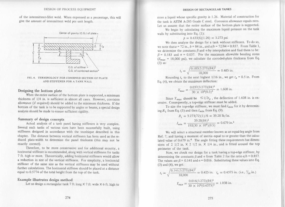
t)tjst(;N otr p t{o(jtr.ss lQUIPMENT
of the intermittent-fillet wetd. When expressed as a percentage, this willgive the amount of intermittent weld per unit length.
Center of gravily {C,G.} o{ plate -
FIG. 4. TERMINOLOGY FOR COMBINED SECTION OF PLATEAND STIFFENER TOR A TANK WALL
Designing the bottom plateWhen the entire surface of the bottom plate is supported, a minimum
thickness of 1/4 in. is sufficient in almost all cases. However, corrosronallowance (if required) should be added to the minimum thickness. If thebottom of the tank is to be supported by angles or beams, a special designanalysis should be made to ensure sufficient rigidity.
Summary of design conceptsActual analysis of a tank panel having stiffenen is very complex.
Several such tanl<s of various sizes have been successfully built, usingstiffeners designed in accordance with the tecnhique described in thischapter. The distance betn/een yertical stiffeners has been used as the re-duced plate-width to detemine the panel thickness (this may not beexactly correct).
Therefore, to be more conservative and for additional security, ahorizontal stiffener is recommended, along with vertical stiffeners for tanks7 ft. high or more. Theoretically, adding horizontal stiffeners would allowa reduction in size of the vertical stiffeners. For simplicity, a hodzontalstiffener of the same size as the vertica.l stiffeners may be used withourfurther calculations. The horizontal stiffener should be placed at a distanceequal to 0.5774 of the total height from the top of the tank.
Fxample illustrates design methodkt us design a rectangular tank 7 ft.long X 7 ft. wide X 6 ft. high to
\'. \'C.G. of stiffner lu.u. or sflrrner rC.G. of combined sectionj
274
v-
27s
DESICN OT RBCTANCULAR TANKS
store a liquid whose specific gravity is l'26. Material of construction for
the tank is ASTM A-285 Grade C steel Corrosion allowance equals zero.
Let us assume that the entire surface of the bottom plate is supported.
We begin by calculating the maximum liquid pressure on the tank
walls by substituting into Eq. (1):y' = 0.a33(6)(1.26) = 3.273 Psi
We then analyze the design for a tank without stiffeners. To do so,
we note thata = 72 in., b = 84 in., and alb = 72184 = 0.851. FromTable 1,
we determine the constants p and d by interyolation and find them to be:
F = O.tg: and a = 0.037. For the maximum allowable bending stress
(S,''o! = 18,000 psi), we calculate the corroded-plate thickness from Eq'(3) as:
= 0.485 in.l8,000
Rounding 1,. to the next highest l/16 in., we get 1a = 0.5 in. From
Eq. (4), we obtain the maximum deflection:
y _ 0.037(3.273x84_)4 = 1.608in.
x 106(0.5)3
Since Y,'i* should be <1l2ta ,I]ne deflection of 1.608 in. is ex-
cessive. Consequently, a toPedge stiffener must be added.
To size the top-edge stiffener, we must find,a,,i,? for it by determin-
ing R 1 from Eq. (5) and then 1-;, from Eq. (9).
R t = 3.27 3(7 2)(t) / 6 = 39.28 tb / in.
/ . - 39 28(B{)'
= 0.679 in.4'"-192(30x106x0.5)
We will select a structural member known as an equal-leg angle from
Ref. 7, and having a moment of inertia equal to or greater than the calcu-
Iated value of 0.679 in.a The angle fitting these requirements has dimen-
sions of 2 ll2 in. x 2 112 in. x 114 in., and is fitted around the topperimeter of the tank.
Now, we check our design for a tank having a top-edge stiffener, by
det€rmining the constants p and a from Table 2 for the fttio ofb = 0 857.
The values arep= 0.141 anda=0.016. Substituting these values into Eq.
(3) and (4), we get:
= 0.425 in. to : 0.4375 in. (i.e., /tu in.)
= 1.038 in.
18,000
0.016(3.273X84r
30 x 106(0.4375)3
'0. r 83(3.273)(84),

The deflection of 1.038 in.is still excessive. Therefore, additionalstiffeners are needed. Let us try adding vertical stiffene$ at a 42-in. spac_ing along the length and width of the tank. For rhis spacing, a/, becomes72142 = 1.714. From Table 2,we now find thatfi=O.294and a= 0.050.
l )lisl(;N oli PltO(llrSS EQUIPMENT
18,000 = 0.307 in.
Therefore:
Y
= 0.3125 in. (i.e., ,f,oin.)
0.050(3.273 r(42 )r= 30 x loloilr5F = 0 556 in'
Again, the deflection is excessive. Let us reduce the stiffener spacingto 28 in., and solve for a rcw afb = 72125 = 2.571. From Table2, weobtain new values forf = 0.387 anda = 0.071. Solving Eq. (3) and (4) forthis condition yields:
= 0.235 in.
to = 0.25 in. (i.e., 1/4 in.)
.. 0.07 t ( 3.17J )(t8 rrr,,,, : 30 xr o,,-io25l = 0.305 in.
The deflection is still excessive. Let us try 5/16-in. plate (i.e., ro =0.3125 in.). Deflection now becomes:
,, o.ol t( 3.213 )\'28)lr,,," = 30 x ro,\ojl2r.r = u.rrb rn.
The deflection is now almost equal to tal2, or 0.3125/2, and issuitable. Since corrosion allowance is zero, let us use 5/16-in. plate for thetank, with veftical stiffeners having a 28-in. spacing.
We now resize the top-€dge stiffener. Neglecting the effect ofverti-cal stiffenem, we calculate the required moment of inertia for the newplate thickness from Eq. (9) as:
, 39.28(84)1r-..=__ __,.* = 1.087in.{t92(30 x 106 )\..,, _,/
From Ref. 7, we obtain the size of the equalJeg angle meeting orexaeedng Imin. Dimensions of the resized angle are: 2 1 12 in. x 2 I li in.X l12 in.
To size the vertical stiffeners, we calculate maximum bendrngmomenr by using Fq. (lO). Hence:
M^* = 0.0642(3.273)(28)(742 = 30,500 in-tb
0.387(3.273)(28)'
276 277
Dt]SICN OF RtsCTAN(iUI,AR 'I'ANKS
{11 dimensions are inches
FIG. 5. COMBINED SECTION OF PLATE AND STIFFENERFOR TANKWALL OF PROBLEM
From Eq. (17), we obtain the section modulus, Z, for this stiffener
as: z = 3o,5oo / l9,ooo = 1.694in.'
For v€rtical stiffeners, we will select an appropriate channel from
Ref. 7 to meet or €xceed the calculated section modulus' The required
channel has dimensions of 4 in. X I 5/8 in., and weighs 5'4 lb/ft' Its cross-
section contains 1.56 in.2
We must now perform a design analysis for the combined section, as
shown in Fig. 5, to d€termine whether the maximum deflection is exceed-
ed. To find the area of the combined section, we add the area of the plate
(28 X 0.3125) and the area of the channel (1 56) to get a total area of 10 31
in.2 By substituting into Eq. (18), we can calculate the combined moment
of inertia as:
8.?5(0.3125)z 8.75(1.s6X2.1563)z/= 3.8 + t2 10.31
= 10.207 in.a
where 3.8 is the moment of inertia for the selected channel about its major
axis, as found from the appropriate table in Ref. 7'
We calculate Cl and C2 from Eq. (19) and (20), respectively:
8.75(0.1s63) + 1.56(2.1563 + 0.1563)
10.31
= 0.4826 in.
C" = 4.3125 - 0.4826 = 3.8299 in.
l=b=29in.

(2r):
I)US I(;N ()I'I PI{(X]ESS EQUIPMENT
We then calculate the maximum deflection by substituting into Eq.
0.00652(3.273)(28X72)rv = 0.0534 in.30 x 106( 10.027)
Channel4 in. X 1sr6;n., 5.416711
Elevation Side
FIG. 6. LOCATION AND SIZE OF STIFFENERS
Since the maximum deflection is considerably less than one half ofthe plate thickness (0.312512),the design is satisfactory.
Finally, we check the maximum bending stress, S1, in the outer fiberof the plate from Eq. (22), and S, in the outer fiber of the stiffener fromEq. (23). These stresses are:
.5'r = 30,500(0.482 6) / 10.0'27 : 1,468 psi
J', = 30,500(3.8299)/ 10.02'r = ll,650psi
Since the allowable value is 18,000 psi, both bending stresses are wellwithin the limit.
We calculate the maximum vertical shear for our configuration fromEq. (24), and find it to be:
v^", = 3.273(28)(12)/3 = 2,200 tb
If we use a continuous fillet weld to attach the stiffeners to the plare,we can d€termine the weld size by substituting into Eq. (25) and assumrngthat the fillet-weld shear, S*, is 10,000 psi,
2,200(8. i5)(0.3263)
,2u2in, X 21t2in. X 1/2 in. Top angle
r 0,000(10.027X2)W=
278
= 0.0313 in.
279
tXlSl(;N oI RLICTANCUt.AR lANKS
Therefore, wc will use a 3/ l(r-nr. minimum llllet weld for attaching
the stiffeners to the tank wall.Since the entire surface of the bottom plate is supported and since
the corrosion allowance is zero, a bottom plale ll4 iI'. thick will be suffi-
cient for this tank. The final arrangement of stiffeners is shown in Fig. 6.
It is important to note that the weight of the tank and its contents must be
transferred to an adequate support structure (if elevated), and ultimatelyto a foundation.
NOMENCLATURE
d Height of tank, in.,4 Area of uncorroded-plate section of width /, in.2
Ar Area of corroded-plat€ section of width /, in.2
b Larger dimension for length or width of tank, in.C Distance from outer fiber ofplate to outer fiber of stiffener, in.
Cr Distance from neutral axis of combined sectionto outer fiberofplate, in.
C2 Distanc€ from neutral axis of combined section to outer fiber ofstiffener, in.
E Modulus of elasticity (for carbon steel, E = 30 X 106), psi
ht Distance between center of gravity of plate section and the neutral
axis of combined section, in.
h2 Dstance between the neutral axis of combined section and the center
of gravity of stiffener, in.h3 Distance b€tween center of gravity ofplate and that of stiffener, in.
I/ Height of tank, ft.1 Moment of inertia of combined section, in.a
1, Moment of inertia of plate section, in.a
./2 Moment of inertia of stiffener, in.alnrz Minimum rcquired moment of inertia of top-edge or intermediate
stiffener, in.a
/ Distance between sliffeners, in.m Unit width of plate, in.
M,n ajr Maximum bending moment in the plate, in lbr Number of continuous welds joining the stiffener to the plate.
p Maximum pressure against side-walls of tank due to weight of con-
tents, psi
Rl Reaction at top edge of tank, lb/in.R2 Reaction at bottom edge of tank, lb/in.R3 Reaction at intermediate horizontal stiffener, lb/in.s Specific gravity of tank contents
Sr Maximum bending stress in outer fiber of plate, psi
,S2 Maximum bending stress in outer fiber of stiffener, psi

l)l;Sl(;N ( )lr Pl{(X;tiSS t)(.lUtPMLjNl
Smdx Maximum allowable bcnding stress in plate or slil.l.eDers, psiS,, Allowable shear stress of stiffener-to-plate weld, psitd Actual corroded-plate thickness, in.// Required corroded-plare lhickness, in.I/-o, Total shear on plate section, lb.ll Lng size of continuous-fillet weld, in.
I-or, Maximum deflecrion of plate. in.Z Section modulus ofvertical stiffener, in.3c Constant (s€e Table I and 2)
B Constant (see Table I and 2)
REFERENCES
1. "Welded Steel Thnks for Oil Storage, " 7th ed., API Standard 650,American Petroleum Institute, Washington, D.C., November i980.
2. Timoshenko, S. and Woinowsky-Krieger, S., "Theory of Plates andShells," 2nd ed., McGraw-Hill, New York, N. Y., 1959.
3. Wojtaszak, I. A., "Stress and Deflection of Rectangular Plates," J. Appl.Mech., Vol. 3, No. 2 (1936).
4. Roark, R. J. and Young, W. C., "Formulas for Stress and Strain," 5thed., Mccraw-Hill, New York, N.Y., 1975.
5. ASME Boiler and Pressure Vessel Code, Section VIII. "Pressure Vcs-sels" Div. 1, American Soc. of Mechanical Engineers, New York, N.Y.,1983.
6. Young, D., 'lBending Moments in the Walls of Rectangular Tanks,,'proc.Am. Soc. Civil Engrs., Vol.67, 1683 (1941).
7. "Manual of Steel Consfucdon," 8th ed., American Institute of SteelConstruction, New York, N.Y., 1980.
8. Blodgett, O. W., "Design of Welded Structures," The James F. LincolnAre Welding Foundation, Cleveland, August 1967.
t4AIR COOLED HEAT EXCIIANGERSPART A _ CONSTRUCTIONAL DETAILS
Air cooled heal exchangers become altractive especially in
Iocalions where water is scarce or expensive 1o treat Although the
initial installed cosl ofan aircooleris usually greaterthan that ofa waler
cooler, the savings in operation and maintenance costs frequentlymake
the air cooler the more economical selection'
Air cooled heat exchanger consists of a bundle of bare or finned
tubes which are rolled or welded into headers Ambient air is moved
across the tube bundle by an induced or forced draft fan The warm
fluid circulating through the tubes, gives up paft of its heal to the air
which is then eipelled lo the almosphere above or around the unil's
circumference. Different tlpes of tubes, headers, and fans combine to
form a wide varicty of overall designs The aim of each is to carry away
unwanted heat as cfficiently as possible, with minimum maintenance'
vibration. and noisc. Two main groups of these exchangers along with
the advantages and disadvantages of each are discussed below t
Induced Draft l}peThese are the types in which the lube bundles are located on the
suction side of the fan as shown in Figure 1.
Advantagesl. Easier 10 shop assemble, ship, and install2. The hoods offer prolection from weather'i. Easier to clean underside when covered with lin4 bugs, debris'
4. More efficient air distribution over the bundle5. Less likely to be affected by hot air distribution
Dlsadvantages1. More difficult to remove bundles for maintenance'
2. High temperature service limited due to effect of hot air on the
fans
Chapter l3 is a sligitly_nodified version ofauthor's study:'A method for Designing Rectangu-far Storagr 'Ihnls' published in Chenical Eneineerine (March 28, 1977). -Cop-yrighted-by
Mccraw-Hill. Inc.
280 281

3.
DESIGN OF PROCESS EQUIPMENT
More difficult to work on thn assembly, i. c., ad just bladcs due roheat from bundlc and their location.
R COOLED HEAT EXCHANCER
Forced Draft \peIn these tlpes, the tube bundlcs are located on the discharge ofthe
fan as showr in Figurc 2.Advantages
1. Easy to remove and replace bundles.2. Easier to mount motors or other drivers with shon shafts.3. Lubrication, maintenance', etc. more accessible.4. With reinforced straight sidc panels to form a rectangular box
tlpe plenum, shipping and mounting is greatly sim-plified, permitting complete preassembled shoptestedunits.
5. Best adapted for cold climale operation with warm airrecirculation.
Disadvantagesl. Difficult to shop asscmble, ship, and install.2. More exposure to weather conditions.3. Difficult to clcan from underside.4. Less efficient air distribution over the bundle.5. Greatly increased possibility of hot air recirculation.
282 283
.IG 2 FORCED DMFT AIR COOLED HEAT EXCI-IANCER
TubesA bare tube is thc simplest and least expensive configuration But
its applicalion is limited because bare round surfaces do not have
sufficient heat rransfcr area A much larger tube bundle and heat
exchanger would be needed to handle the same duty Fins can expose
from eighl 10 lwenty times more tube sur{ace and thus result in
dissipati,on of more hcat from a given diameter of lube'
Selection of mosl economical exchanger requires careful
consideration of many component variables. It is extremely imporlant
to use standard designs ifat allpossible. Tube and fin sizeand materials
are limited to what can bc manufactured economically' One inch O D'
and thirty feet long tubes arc most common Fin height varies from '/2
inch to 7, i.r.h and fin pitch varics from 8 to I I fins per inch' Othertube
sizes can also be used if found economical for any applicarion
Bare rubes should be used where the process temperature ls very
high and whcre thc heat lransfcr rate on the process side is very low'
Where these conditions cxist, il is good practice to provide both bare
and fin tubes in onc sewice'. When the process inlet temperature is loohigh for the fin tubc, thc fir-sl pass may be bare tubes Likew]se, for rhe
last pass, where thc coolcd stream has a lransfer rate in the viscous
region.
Finned TubesFinned tubcs zrrc available in a wide range of shapes and
materials. Some of thc most popular designs are discussed below'
Each of these tlpes is dcsigned for a given temperature range
AIR COOIfD HEAT EXCHANGERS

DESIGN OF PR@ESS EQUIPMENT
depending on materials used and operating conditions. Each will givemaximum service for a given application when correctly usedTension Wrapped Embedded Flns
This type of fin, as shown in Figure 3, is tighrly wound into thgroove to produce an inlerference fit on both sides andbottom toinsuretight contact between fin and 1ube. This is good for design temperatureof up to 750'F. It has the disadvantage of an exposed bimetal contactand provides no protection for the steel liner.
FIG. 3 . TENSION WMPPED EMBEDDED FINS
Extruded Flns
- This is the most expensive tlpe. It is produced by slipping analuminum tubeoverthe coretube, thealuminum fin is th".,
""i-d.dbyrolling the muff Extrusion operation builds up an inlerference fitbetween the two tubes producing complete mechanical bond" Thisdesign actually consists of a tube within a tube and the fins Drotect thesurface of the core tube as is shown in Figurc 4. Il is go;d through550"F design temperature.
FIG. 4 . EXTRUDED FINS
Single Footed Tension Wrapped FinsThis type, as shown in Figure 5, is good for design temperature of
up to 350"F. Contact between fin and tube is obtained by applyingtension during finning The heel of one fin fits snugly againsi rheioe ofthe preceding fin thus completely covering the base iube and shieldrnsagainst atmospheric corrosion.
284285
AIR COOI.ED HEAT EXCHANGERS
FIG, 5'SINGLE FOOTED TENSION WMPPED FINS
Double Footed Tension Wrapped Flns--- itrit typ", ^,
shown in Figure 6, is obtained in the same way as
"in"rc}oot"a' fl"t und is also good for the same temperature range ln
;;i"";;il;;";i"f one fin [iri directlv upon the toe ofrhe preceding fin'
iltr'"d;;i;;;if.tr "
more posil ive shield berween the base tube and the
atmosphere than the single footed t)?e
FIG' 6 - DOUBLE FOOTED TENSION WRAPPED FINS
Edee Wound Tension WraPPed Flns--"- ft i"..i^pf. tension wound type of fin and is shown in Figure 7(a)
and(b). It is good for 300"F of maximum design temperature'
FIC.7 - EDGE WOUND TENSION WRAPPED FINS
Hot Dtpped Solder Bonded Fins
These tlpes offins are attached to thc tubes by soldering and then
aiop"a-ttoi ln tot"tiorr. Its use is limited to 250"F maximum design
temperature because of their constmction
Headers---- H"^d".
"on"truction is important because they tie the exchanger
t"b., t-";;"; itilo a bundle. They also-provide accets to the,inside of
tuU". i.i "*f" removal and' occasionaliy' for replacing a tube in the
(b) On Knurlcd rubc

DESIGN OF PROCESS EQUIPMENT
bundle. ln an air coolcd heat cxchanger, tubc ends are bare of fins inorder that the rubes can be roller expanded and/orwelded into headers.Various t,?es of headers along with their applications are discussedbelow.Plug gpe Header
This is the most common type ofheader. It has plugs opposite thetubes to allow for tube rolling and cleaning Box t5pe headers can befabricated from side plates and two end plates using corner welds asshown in Figure8 (a). In applicarions(such as lethal service, etc) whereextensive nondeslruclive testing is required, plates can be bent to,,C"shapes and butt-welded togetheras shown in Figure 8 (b). Box headershave been built with design pressures up to 3,000 psi
FIC. 8 . PLUC TYPE HEADERS
Cover Plate 1}pe HeaderThis type has bohed cover plate as shown in Figure 9 and thus
does away with the need for screw plugs. This should be spc.cified forstreams with fouling factor of.003 or more and where entrained solidsmay settle ou1 in the bundles. Because of gasketed joint at thecoverplate, use of this type is limiled to design pressure oi350 osi andtemperatu rc o[ 400'F.
(a) Fab.icaied Bo\ T.We (b) 'C" Shapc Type
COVER PLATE TYPE HEADER
286 287
AtR COOLED HEAT EXCHANGERS
Manlfold \pe HeaderThis typc utilizcs cylindrical hcadcrs with U-tubcs as shown in
Figure 10. iLese arc suirablc [orhigh prcssure applications' Chemical
cleaning and flushing conncctions may be added to handle dirty
streams in the cylindrical hcadcr This tJ,rpe cannot be used where
periodic tube cleaning is ncccssary.
:OLD ryPE HEADER
Billet lype HeaderThis tlpe is shown in Figurc 1l and is also suitable for high
pressure applications. In this, a solid metal billet is drilled with flowpassages. The bored fluid passages are manifolded inlo pipe ormachined collecting chamberu depcnding upon the pressure
FIC. I I -,BILLET TYPE HEADER
DESIGN OF PROCESS EQUIPMENT
Steam CollSleam coils are used 1o heat the fin tubes to prevenl fluids from
solidification or freezing inside the tubes on stan-up, shutdowrr, oroperating conditions.
Fans
Moving air should be distributed as evenly as possible across thetube bundle. Poor distribution can create areas of very little airmovemcnt resuhing in reduced cooling effectiveness ofthe finned tubebundle and an increase in power consumption. Axial flow, propellertlpe fans are used to movc and distribute air across the air cooled heatexchangers. In forccd draft the fan forces the air across the bundlewhile in induced draft" it draws air across the bundle. Two fans arcusuallv provided forcach bay, This assurcs continuous operation wtrnonc fan out ofservicc. Also, at reduced loads and during coolerweatner,it mav feasible to opcrale with one fan out of sewice as an aid to controland for economy.
Fans may have fixed oradjustable pitch blades. However, most ofthe fans in the air cooled heat exchanger application have adjustablepitch blades. Adjustable pitch fans are either manually adjustable orautomatically adjustable Most automatic adjuslable pitch fans causefan pitch change by means of a pneumatically actuated diaphragm.
Mechanical EquipmentThe fan drivers are electric motors, steam lurbines, gas or
gasoline engines, orhydraulic motors. The most commonlyused driverfor air cooled heat exchangers is the electric molor. Steam turbines aresometimes installed as a back-up for electric motors in the event ofpowerfailure and to permit variable fan speed control. V-behs and rightangle bevel gears are used as the speed reducer of these drivers.
PlenumThe air plenum is completely enclosed space which provides for
the smooth flow ofairbetween fans and bundles. plenums are desisnedas a transition type or box type. The lransition type givcs rhelesrdistribution of air over the bundles but is usuallv used onlv on induceddraft because o[ slrucrural difficuhies with forced drah
StructureThe structure consists ofthe columnq braces, and cross beams ro
support the exchanger of a sufficient elevation above ground to allowthe necessary volume of air to enter below al a reasonable approach
AIR COOLED HEAT EXCHANGERS
velocity. In oil rcfinerics and chcmical complexes' to conscrvc ground
space, air cooled heat exchangers are usually mounted above cxisling
oine.u"k, with other equipment occupying the space underncath the
pip"auaL The piperack and air cooled heat exchanger structures are
integrated
REFERENCES
1. API Standard 661 , "Air-Cooled Heat Exchangers for General
Refinery Sewices", Second Editioq January, 1978'
288 289

I)ESICN OI: PROCESS EQUIPMENT
AIR COOLED HEAT EXCHANGERSPART B _ IIEADER BOX DESIGN
Introduction
- The technique for mechanical design analysis of header box withoutbolted cover and subject to intemal pressure for alr cooled heat ex.t uneaaa ,,discussed. The analysis is in accordance with Appendix f.}, ofSection'VIflDivision 1 of the ASME Boiler and pressure Vessel Code. r
The discussion is limited to very common configurations of a headerbox in which the opposite sides have the same wall thiikness. f*o opoo.it"sides may have a wall lhickness different than thar of the othe, i*" "ii"ri"sides. The walls are considered fairly thick and there is no rounjiii'"i,rr"comers. The tubesheets and plugsheets are considered pertoratea Tor ttretubes and removable cleaning plugs.
Design Criteria
The formulas given require solution by assuming a thickness or thick_nesses f9f t9q and bottom plates and tube und plug plals and sotvlng fo. tfresh€ss which is then compared with an allowaLle;;ess value. The a"ssumeothicknesses are used in the formulas to calculate both membran" una U""Olngstresses. Ail_membrane stresses generated by mechanical loads are limitedro rne alowatrte tensile stress values listed in the appropriate stress tables ofthe ASME Code. Any combination ofmechanicallyinduced."rnf.un" otu,bending stress. should not be greater than one and a fratf times tfre Joaeatiowable tensrle stress-
.^. Tl" "llflg": are designed in accordance with Uc_34(c), Fdragraph(3) of the ASME Secrion VIII, Division I Code.Comerjoint construction is mostly used for header boxes of air cooled
IrT exclrT-C:js:The comerjoint weld efficiency can always U"urrurn"Ju,1.0 per ASME Code. For locations other than comers, ,rja ;oini
"ffi'"i"ncies as given in UW-12 of ASME Code should be used in Jr"r, _uiyri..
290 291
AIR COOLED HEAT EXCHANGERS
However, fbr tube and plug platcs, thc ligament clliciencies should bc used
in both membrane and bending stress calculations For simplicity and
conservative design, ligament efficiency based on the pitch diameter of
iiJ. in plugtnJ"t cai be used for both these plates for plug type-header
Uoxes. foicoierptate type of headers, the tube hole diameter in tubesheet
should be used for determining ligament efficiency'
Figure I covers the design of the header box without Partition or
stiffenei. Figure 2 shows the boi with single partition or stiffener located in
itr" ""*". ihe analysis of Figure 2 are also applicable to two unequal
compartments when ihe anatysis of both the compartments are based.on the
larger size. Figure 3 represents the box with two equally spaced partitions or
stiifeners. Cases of three or more unequal compartments can be analy-zed
*ith th" pro."du.". of Figure 3 provided the design is based on the size of the
largest comPartment.
Analyzing Procedure for Header Box of Air Cooled Heat Exchangers
without Partition or Stiffener
*ttI
II
{
Let Et =Ez=
weld joint efficiency (from Thble UW-12 of ASME Code)
Ligament efficiency = (P - d) i P
. (t, )r , (t2)3I. = -:--.)-:- L --'' r) ' 12
H_-c=lK:(Irll,)oh
Nl
iP_L_
II

DESIGN OI: PROCESS EQUTPMENT
Stress Calculations
Membrane StrtssTop and Bottom Plates
(S^) t, = Ph / (2trEr)
Thbe and Plug Plates
(S)t2: P}l/(2t2E2)
Bending StressTop and Bottom Plates
(s/N= - Pc fr.s ut-t,t
12 l1E1 L
(l + q2 K)
l+K/.S,)O: + Ph2 c (l + a2K)
12 rr(l) (l + K)
Tbbe and Plug Plates
(s.tM=-r ph2 c l-,. (t + q2K, I12 l2E2 L l+K J
Ph2 c (l + ctz K)(l +K)12 I2(r)
Tbtal StressesTop and Bottom Plates
(s,)N = (S-) tr + (SJN, (sJQ = (S-) t, + (Sb)e
Tirbe and Plug Plates
(s,)M : (S-) t2 + (SJM, (S,)O : (S-) t, + (Sb)e
End Platos
z = ft+ - 2.4 5.(maximum z = 2.5)\ h/
C = 0.33
r:' /cPz'' "VsE,
292 293
AIR COOLED HEAT EXCHANGERS
Allowsble Stresses
S = allowable membrane stress
= allowable tensile stress for plate material at
design temperature
Allowable total stress = 1.5(S)
Assumed thicknesses should be revised until all the calculated stresses
fall within the allowables. Corrosion allowance, if required' should be added
to these thicknesses to determine the final plate thicknesses'
Analyzing Procedure for Header Box of Air Cooled Ileat Exchangers
with Single Partition or Stiffener
,,]=-
.:Lf
"T_- I
_l__]"f-l__r- Ill'l
FJI]URE 2 _ HEADER BOX WITH SINGLE PARTITION OR STIFFENER
: Weld joint efficiency (from Table UW-12 of ASME Code)
= Ligament efficiency = (p - d) / P
: Weld joint efficiency for Partition or stiffener(from Table UW-12 of ASME Code)
Let EjF
E
- (t')3', t2
H
h
(L)l-t2
K = (12 | I)q

DESIGN OF PROCESS EQUIPMENT
Stress Calcutations
Membrane Stresslbp and Bottom plates
(s)tr : Ph Ia - {z--t-!A-::?t14ttEt t I t+2K IJlirbe and Plug Plat€s
(S)t, = P11 112rP",
Partidon or Stiffener
(s^)tt : en fz_frO_S112 tou" L l+2K I
Bending StrtssIbp and Bottom platss
(s)N =a Pc lzu, zntl l+2a,K \lZ4ltEt L t l+2K lJ(S)e :+ Ph2 c I t +2a2K I
12 Irfl) L l+2K IThbe and Plug Plates
(SbM =+ Ph2c fl+K(3-q2)lr2\E2L 1+rK I
(5,)e =* Ph'zc f I + 2crK 112r2(l) L ll21<-l
Ibtal StressesTbp and Bottom platas
(,s,)N:(S-)tr+(sJN,
lirbe and Plug Plates
(5,)M = (S^)q + (sb)M,
Partition or Stiffener
S, = (S..X+
(sJO=(s-)t,+(sJe
(sJC=(s_)t,+(sJe
294
AIR COOLED HEAT EXCHANGERS
End PlatesLIZ =(3.4 - 2.4!), maximum Z = 25\n
Allowable Stresses
S = allowable membrane sfess
= allorrable tensile saess for plate materialat design temperature
Allowable total shess = 1.5(S)
Assumed thicknesses should be revised until all the calculated stresses
fall within the allorrables. Corrosion allowance, ifrequired, should be added
to thes€ thicknesses to detennine the final plate thicknesses'
Analyzingwith T\vo
C =0.33, b =H @V t""
FIGTJRE 3 - HEADER BOX 1VTIH TWO OR MORE PARITTIONS. AND/OR STIFFENERS
Let E1 = Weld joint efficiency (from Table IJW-12 of ASME Code)
E. = Lieament efficiency : (P - d) / Pfi = Weta joint efficiency for partition or stiffener
(from Table UW-12 of ASME Code)

DESIGN OF PROCESS EQUIPMENT AIR COOLEI) HEAT EXCHANGERS
t2
H
h
r, : ()3-t2
K =(Ir/tr)u
'lbbe and Plug Platcs
19,)M=(S,")t2+(Sb)M'Irortitions and/or Stiffen€rs
(S,)O=(S-)t2+(Sb)Q
,!, = (s-)ta
Ilnd Plates
z :(t.q - 2.4H\, (maximum z = 2'5)\ h/
Stress Calculations
Membrane StressTop and Bottom Plates
PhFr(s-/r,=-13-,{2ttEt L (
TUbe and Plug Plates
(S^)tr = PH / (2t2E )
Partitions and/or Stiffeners
6 + K(ll - a2) )3+5K )3+5K
C :0.33, ts : H
Allowable Stresses
.S = allowable membrane stless
= allorvable tensile stress for plate matedal
at design temperature
Allowable total stress = 1.5(S)
Assumed thicknesses should be revised until all the calculated stresses
f"[ *i;i;;;"u"*ables. Corrosion allowance ' if required' should be added
io ihese thicknesses to determine the final plate thicknesses'
EXAMPLE
Check the design ofa single pass plug type headerbox-for an air cooled
h"at exchange. for -100
psi intemal piessure at 400"F Allow 7re inch for
.orr*in ufio*-"". Us; SA-285-C material for all the plates The various
t "uO"a
Uo* Parameters in uncorroded condition are as follows:
ToD and Bottom Plate Thickness .375 inches
Bending StressTbp and Bottorn Plates
/c l^r -r Pctu b,r - !
24 ItEl
Tbtal StressesTop and Bottom Ptates
(sl)N: (s-)tr + (sJN,
6+K(ll-Ctr)l3+5K J3+5K
f.,, - zn' (J -i )c. l(3+5K )l
(S)e =t Ph'?c / 3+5q2K \12 r,(l) \ 3+5K I
Ihbe and Plug Plates
(S)M:t Ph'?c f12 I2Ea L 3
(SlQ = t: Ph2 c (12 Ir(l) \ J+JK
q")K(6 -3+Tirbe and Plug Plate Thickness
End Plale Thickness
Inside Header Width
Inside Header Height
Inside Header Length
Pitch of Tirbe Holes
Pitch Diameter of Threads
in Plugsheet
= 1.25 inches
= .5 inches
4 inches
12. 125 inches
114.75 inches
2.375 inches
1.1875 inches
-5K
JO'
(sJQ=(s_)tr+(sJQ
296297

DESIGN OF PROCESS EQUIPMENT
I
*{ " I
f-ltl*T-
FIC. 4 _ EXAMPLE PROBLEM FOR HEADER BOX WITHOLN PARITTION
Refening to Fig. 4, we have
tt = .375 - .0625 = .3125 inches
tz = 1.25 - .0625 = t.1875 inches
b = .S - .0625 = .4375 inches
h : 12.125 + .0625 + .0625 = 12.25 inches
4 : 114.75 + .0625 + .0625 : 114.875 inches
H = 4 + .0625 + .M25 : 4.125 inches
Materials of construction: SA-285-C
Design conditions : 100 psig at 400"F
Er : 1'0
E2 = Ligament efficiency for membrane & bending stresses for tubeand plug plates
= (p -d) / p = (2.37s - 1.1875) t 2.375 : .5
1, : Moment of inertia of unit wide top or bottom plate
- (tr)3 : .0025 in.a/in.12
SOLUTION
298 299
AIR COOLED HEAT EXCHANGERS
1z : Moment of inertia of unit wide tube or plug plate
= (t )3 = .1395 in.a/in.t2
q. : Rectangular box parameter = !: o.rrt / 12.25 : .3367h
K : Vessel parameter = (I2 / Ir)ct = 18.7879
Stress Calculations
Membrane StressTop and Bottom Plates
(s^)t-Ph / (2trEr) :100 (12.25) /2(.3125)1.0 :1,960 psi
lhbe and Plug Plates
(S^)tt =p11 1 (zhU) = 100 (4.125) / 2(1.1875\.5 :347 psi
Bending StressTbp and Bottom Plat€s
,c ,a/ _ + Pc I l.5Ht - tr (l + a'zK)l(rN:= ta"E, l_'..' t-K l
_ _+ 100(.rs625) | t.s,q.nsr, _ 12.252 tl + .33672 (18.7879))lf
12(.0025)r.0 L "-' '-', (1 + 18.?879) I
= -r 931 psi
(sr)Q : ! Ph2 c (1 + ct2 K)
12rl1) l + Kr00(r2.2s)2 (.r562s)
(.1582) : -f 12,365 Psi12(.0025)r
Thbe and Plug Plates
Ph2 c I rt + q,K)lts.tM : =- I 1.5 - -------------- l
12 l2E2 L l+K
__+ 100(12.25\2 .59375 (1.5 _.1582)=+ 14,284 psi12 (.1395) .5
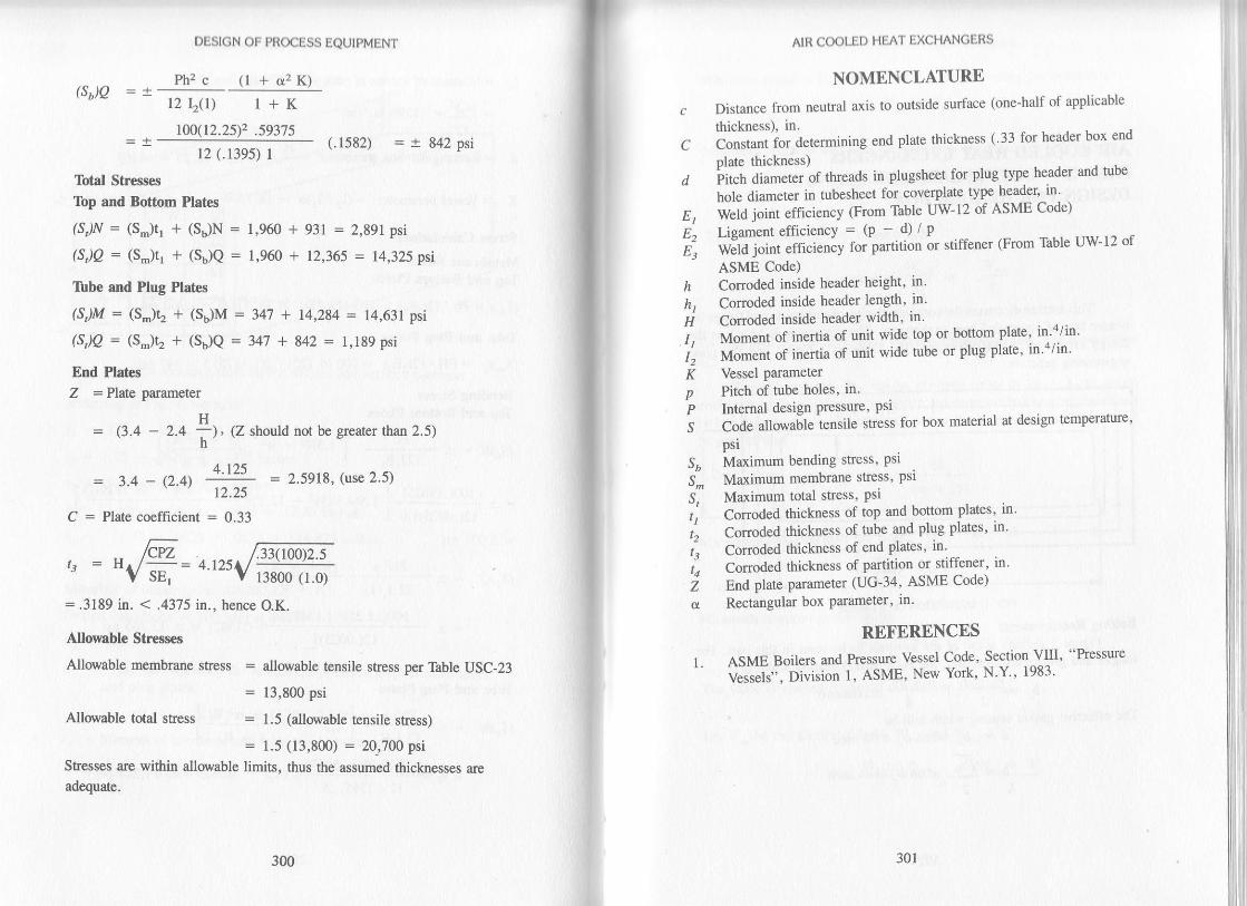
(S)Q
DESIGN OF PROCESS EQUTPMENT
Ph2 c (l +c2K)l2 120\ I + K
t0[/(12.25)2 .59375(.1582) = 'r 842 Psi
12 (.139s) 1
lbtal Stresses
Ibp and Bottom Plat€s
(S,)N = (S-)tr + (S6)N: 1,960 -r
(sJQ: (s"Jq + (sjQ = 1,e6i a
931 = 2,891 psi
12,365 = 14,325 psi
Ibbe and Plug Plaies
(S,)M = (S-)t, + (Sb)M : 347 + 14,2U = 14,631 psi
(S/9 = 6-)t2 + (Sb)Q = 347 + 842 = 1,189psi
End Plales
Z =Plpne parameter
H: (3.4 - 2.4 -)' (Z should not b€ geater than 2.5)h'
4.r25: 3.4 _ e.4't : = 2.5918, (use 2.5)12.25
C : Plate coefficient = 0.33
,. /cYz .. .-_ /.33(rN)2.5
" = HVd= 4 t25V
l38oo t'Ji= .3189 in. < .4375 n., hence O.K.
Nlouable Stresses
Allorable membrane stress = allorvable tensile stress per 1bble USC-23
Allowable total stress
= 13,80 psi
- 1.5 (alloxable tensile stress)
= 1.5 (13,800) = 10_,700 psi
Stresses are within allorable limits, thus the assumed thicknesses are
adequate.
300 301
F
E3
AIR COOIJD HEAT EXCHANGERS
NOMENCLATURE
Distance from neuFal axis to outside surface (one-half of applicable
thickness), in.6on.*i it O","..ining end plate thickness ( 33 for header box end
plate thickness)Fi"f, a#."t
"f tft .ads in plugsheet for Plug tyPe header and tube
hole diameter in tubesheet for coverplate type header' in .
Weld joint efficiency (From Table IIW-12 of ASME Code)
Lisament efficiencY = (P - d) / P
i;ld l;il;iil;v ror partition or stiffener (From rbble uw-12 of
ASME Code)
h Conoded inside header height, in'
h, Cormded inside header length, in'
i Conoded inside header width' in'
;, i|;rrrerrt of inertia of unit wide top or bofiom plate' in a/in'
t'. Moment of inertia of unit wide tube or plug plaie' in "/m'
Ii vessel Parameterp Pitch of tube holes, in.
P Intemal design Pressure' Psr
S CoO" alowaile tensile stress for box material at design temperature'
psi
Sb Maximum bending sness' Pst
S- Maximum membrane stress' Psl
S, Maximum total stress, Pslil Conooea thickness of top and bottom plates' in
11 Conoded thickness of tube and Plug plates' in'
t", Conoded thickness of end plates, in'
t', Conoded thickness of partition or stiffener, in'
i nnA pl?d! parameter (UG-34' ASME Code)
a Rectangular box Parameter. in'
REFERENCES
1. ASME Boilers and Pressure Vessel Code' section VIIr' "Pressure' V"*"ft", Division l, ASME, New York' N Y'' 1983'

AIR COOLED IIEAf, EXCHAi\IGERSPART C - COVERPLATE AND TLANGEDESIGN FOR IIEADER BOX
This section discusses the complete design ofcoverplate and flange forleader box of air cooled heat exchangen. Th. dir"urrion i, U"*A.1-n"design criteria of ASME Section vIiI, oi"i.io, r-C"J"i *i*tiJ!*aengineering practice.
Bolting RequirementsFigure I defines some of the svmbols fo he rced in rhi. --* r
tonsue and groove construction, ;; 'Jfl"ll1l"i:J,i,l*'l,tj,i,l* *o'
o -* * T. , wl-!-
The effective gasket seating width will beb = b", when b" < Ve inch
b = Ybo . when D" > Z+ inchz
FIG, I. DEFTNI ON OF SYMBOLS
302 303
AIR COOLED HEAT EXCI{ANGERS
Minimum required bolt load for initial gasket seating per bolt pitch
W^2 = B"b Y
Minimum required bolt load for operating condition per bolt pitch
w^, = 9g" P + 2bB"nP2
Therefore, required area of each bolt
w-" w-,A- = greater of 4 or l;
The root area, Ar, of the chosen bolt size should be equal to or greater than
The bolt spacing, 8", can be assumed equal to 24 +- b3 to obtain
unUonn ioaO OistriUutiin on the gasket' However, the bolt spacing should not
U"i"o tft*,ft" rnl"imum required for wench clearance Also' it should not
be greater than
2o + 6b'
(n + .5)
Maximum available load Per bolt
W': Af"
Minimum required gasket width
N ^t"
: AuS" / 28" Y
The value of chosen N should not be less than N,,t,'
tatW^be the greater of loads W^r all.d W*z'
*JLiHt" =ryt

DESIGN OF PROCESS EQUIPMEM
Cover Plate Deslgn
Cover Plate
FIG. 2, COVER PLAIE AND FLANGE ASSEMBLY
Cover plate and flange assembly is shown in Figure 2.
Plate parametel Z, is
Z=3.4 -{ g rt$eater than 2.5)GI
Thickness of the cover plate can be deterrnined by
t": G
Where C, the plate coefficient, is equal to 0.3.
The greater of the groove depth or the desired corrosion allowancomust be added to the calcula0ed cover thickness to obtain the final thickness.Howeve4 the net coverplate thickness under the groove shall not be less than
ffihoSP
"G'
304 305
AIR COOLED HEAT EXCHANGER9
Ileader Flange Deslgn
FIC, 3. FLANGE AND END PLAIE ASSEMBLY
Refer to flange and end plate assembly in Figure 3, we have maximum
bending moment at flange end due to bolt load' IV,
M=WX
Moment of inertia of effective flange section about vertical centerline
tb,3 / b, b" \2,=r; +zbtb\; *; )
Section modulus of effective flange section about vertical centerline
Iu( = -=-br/z b3
Cross-sectional arsa of effective flange section
A = 2bttr
Maximum bending sress in the flange section
Ft=MlS,"E
Maximum dhect stress in the flange sectionFd=WIAE
End, Top and Bottom Plate

DESIGN OF PRoCESS EQUIPMEM
Maximum resultant stless in the flange
F,= Fu*Fo
Flange thickness is adequate if the resultant stress falls within the allowablestress for flange material.
ExampleCheck the design of bolted coverplate and flange for header box of air
crytgO exghg_Se1 Aesigned for 50 psi at 329'F. % inch thick , Vz inch wide ,soft iron doublejacketed asbestos filled gasket with tongue and groove typeof construction is used. The bolts are % inch diameter an d at{spaced 2%inches apart. Coverplate and flange material is 5.4_516_70 and Si-193-B7bolts are used. The coverplate has %6 inch deep and %o inch wide groove andend; top and bottom plates have t% inch deep and /z inch wide tongue. /r inchof corrosion allowance is allowed wherever applicable. Addi--tional datarequired for evaluation is as follorvs:
Longitudinal thickness of flange toplate weld
Total longitudinal thickness of flangeHeight of gasket load reactionlffgth of gasket load reactionRadial distance from gasket load
reaction to the bolt centerTotal thickness of coverplateRadial thickness of flange ring
= .4375 inches= 1.25 inches= 16.5625 inches
= 153.9375 inches
= 1.15625 inches= 1.5 inches= 2.0 inches
Radial distance from outside of plateto the bolt center = .g4375 inches
SolutionIa this case, we have
a = .75n.4 : .4375 in.bz = l '25 n'bz = 1.25 - 2(.4375) = .375 in.B" = 2'75 n'E=.8G = 16.5625 in.Gr = 153 '9375 n'hc = 1.15625 in.m = s.tJ tn.
306 307
AIR COOLED HEAT EXCHANGERS
T:
.5 in.50 psi25,000 psi25,000 psi17,500 psi1.5 in.2.0 in..125 in..5 in..84375 in.7ffi
x=
De.rign Calculations for Cwerptate and trlong€ for Header Box of AirCooled Exchangers
Bolting RequirementsBasic gasket seating width
.5 +.t25 5+ 5b^ = ''---:---:=' ( : maximum)
= .3125 in. (.25 in. maximum)
Use b" = '25 io'
Effective gasket seating widthb = '25 in'
Minirnum required bolt load for ioitial gasket seating condition per bolt pitch
W^z = B"b y
= 2.75 (.2s) 7@0
= 5,225 lb
Minirnum required bolt load for operating condition per bolt pitch
GW^r=18"P+2bB"mP
=,'# Q'75)50 +
Required cross-sectional area of each boltA^ = crealar of w,e I S" or W^, I Su
5.225 | 25 'W : .2A9 in.2
2 (.25') 2.7s (3.75) 50 = 1,397 tb
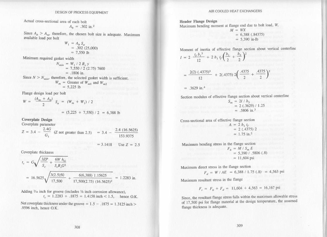
DESIGN OF PN@ESS EQUIPMENT
Actual cross-s€ctional area of each boltAb - '302 in'2
Since d > A-, therefore, the chosen boft size is adequaie. Maximumavailable load per bolt
W, = AuSo= .302 (25,q00)
= 7,550 lbMinimum rcquired gasket width
N^,,=Wrl2B"y= 7,550 | 2 (2.7s) 1ffi: .1806 in.
Since N > N.,r, therefore, the selected gasket width is sufficient.W- = Cre et of W*, md W^.
= 5,225 tb
Flange design load per bolt(A +AI
S"- M^+w)t2
= (s,225 + 7,550)/2 = 6,388 lb
Coverplatr DesignCoverplat€ parameter
2.4GZ = 3.4 - ^
(Z trc/. $earer than 2.5)(rt
Coverplate thickness
t"=Gsp,c2
6(6,388) r.15625
AIR COOLED HEAT EXCHANGERS
Header Flange DeclgnMaximum bending moment at flange end due to bolt load, W
M=W= 6,388 (.84375)
= 5,390 inlb
17,500(2.7 5) (16.5625\2
Mding 3Aa inch for groove (includes % inch corrosion allomnce),t" = 1.2?,83 + .1875 = 1.4158 inch < 1.5, hence O.K.
Net coverplal€ thickness under the gmove : 1.5 - .1875 = l.3l25inch>.9596 inch, hence O.K.
Moment of inertia of effective flange section about vertical centerline
,=r++zr,q(f,+f,)'
= .3629 lll.'4
Section modulus of effective flange section about vertical centerline
'" =7,#?,'"
Cross-sectional area of effective flange section
^
=ii,:i,:t,Maxirnum bending sfess in the flange section
Fr = M lS^E= 5,3W | .5806 (.8): ll,6Mpsi
Maximum direct stress in the flange section
Fa: w t AE = 6,388 / 1.75 (.8I = 4,563 psi
Maximum resultant sfi€ss in the flange
F" = Fr + Fa = ll,604 + 4,563 = 16'167 Psi
Since, the resultant flange stress falls within the maximum allowable shess
of 17;500 psi for flangi material at the design temperature, the assumed
flange thickness is adequate'
- r6.56?s
2.4 (r6.s62s\
r53.9375
= 3.1418 Use Z - 2.5
= 1.2283 in.:3(2.5)50
308

aAAb
bb"brb2
b3
4cEFbFdF,GGrhcI
mMffN^t,Ps"s,,t"s_
tc
.fTwwwrwW^r
DESION OF PROCESS EQUIPMENT
NOMENCLATUREDianeter of bolts. in.Cross-sectioual area of effective flange section, in.2Actual cross-sectional area of each bolt, in.2Required cross-sectional area of each bolt, in.2Effective gasket seating width, in.Basic gasket seating width, in.Longitudinal thickness of flange to plate weld, in.Inngitudinal thickness of unwelded flange, in.Total longitudinal thickness of flange, in.Bolt spacing, in.Constant (.3 for coverpla0e thickness)Flange !o plate joint efficiencyMaxirum bending stress in the flange section, psiMaximum direct shess in the flange section, psiMaximum rcsultant sffess in the flange section, psiHeight of gasket load reaction, in.I€ngth of gasket load reaction, in.Radial distance ftom gasket load reaction to the bolt center, in.Moment of inertia of effective flange section about vertical cen_terline. in.aGask€t faciorMaximum bending moment at flange end due io bolt load, inlbWidth of gasket, in.Mnimum required gasket width, in.Internal design pressure, psiAllorrable stress for bolt material at atrnospheric temperatue, psiAllowable shess for bolt material at design temperature, psiAllwable stess for cover material at design temperature, psiSection modulus ofeffective flange section ;bout vertical ce;terline,ln,,Tbtal thickness of coverplate, in.Radial thickness of flange ring, in.Thickness of the gasket, in.Width of the tongue, in.Flange design bolt load per bolt, lbMaximum available load per bolt, lbGreater of the loads Wtdr and W_r, lbMinimum required bolt load for the operating conditions per boltpitch, lb
AIR COOLED HEAT EXCHANGERS
W-, Minimum required bolt load for gasket seating per bolt piich' lb
X Radial distance from outside of Plate to the bolt center, in'
) Gasket seating shess, PsiZ Coverylalg parameter (UG-34' ASME Code)
RETERENCES
l. ASME Boilers and Pressure Vessel Code, Section VItr, "Pressure Ves-
sels", Division 1, ASME, New York, N.Y'' 1983'
310
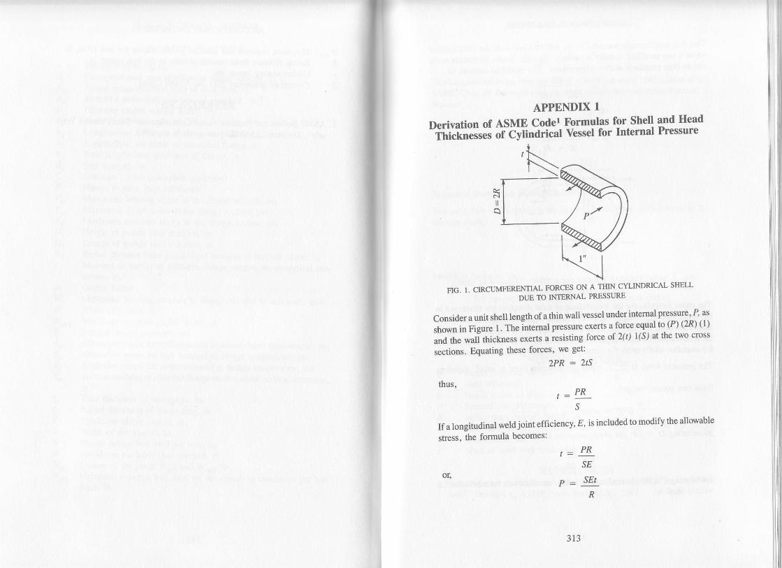
APPENDIX 1
Derivation of ASME CoderThicknesses of CYlindrical
Formulas for Shell and HeadVessel for Internal Pressure
FIG. I. CIRCUMFERENIIAL FORCES ON A THIN CYLINDRICAL SHELL
DUE TO INTERNAL PRESSURE
Consider a unit shell leng$ of a thin wall vessel under intemal pressure' P' as
Ji.*" i" rle-"." r. m" Intemal pressure exerts a force equal to (D (2n) ( l)
and the wali thickness exerts a resisting force of Z(t) 1(S) at the two cross
sections. Equating these forces, we get:
?'PR = 2tS
thus,,:PR
s
If a longitudinal weld joint efficiency, E' is included to modify the allowable
stress, the formula becomes:
=PRSE
_ SEI
R
or'
313

DESIGN OF PROCESS EQUIPMENT
This thin wall formula was used in the ASME Code until the 1942 Editionwhen it was modified to more accurately calculate results for thicker wallsdue to high pressures and/or temperatures. The modified formula is:
t= PR
sE - .6P
SEt
o!
R + .6t
FIG. 2. TONCITUDINAL FORCES ON A THIN CYLINDRICAL SHELLDUE TO TNTERNAL PRNSSURE
The stress formulas for the longitudinal or axial direction are developed inthe same way. Referring to Figure 2, in order to maintain equilibrium in theaxial direction, the iniemal force exerted against the vessel end closuresmust be resisted by the strength ofthe metal in the cross-section of the vesselfor seamless shells <ir by the circumferential weld joints for welded shells.
The pressure force is nD'P while the resisting force is rDrS. Equating4
these two forces, we get:
nPD-Dp : tDtS oB t =-445
Substituting D = 2R, the above equation becomes,
. _PR25
Introducing E as the circumferential weldjoint efficiency, fte expression forwelded shell is:
314 3ls
SHELL AND HEAD THICKNESS
R - 0.4,
Spherical Shells and Hemispherical Heads
The same thin wall formula is obtained as for the longitudinal stress in the
circular shell,
This longitudinal stress formula was also modified in the 1942 Edition of the
ASME Code for the same reasons as the circumferential stress fonnula, itbecame:
2SE + 0.4P
or,
PNt =- ol25E
PR
25E
Modified formulas are:
For henrisPherical heads'
PLFor spherical shells,
PRt=2SE - .2P2SE - .2P
DET
PRs
NOMENCLATURElnside diameter of shell or head' in.
Joint efficiencyInside radius of dish, in.Internal design pressure, PsiInside shell or head radius, in.Atlowable tensile stress for shell or head material at the design
t€mperature, Psir Shell or head wall thickness, in.
REFERENCESl. ASME tsoiler ancl hessure Vessel Code, Section VIII, "Pressure Ves-
sels," Division 1, ASME, New York, N'Y., 1983.

APPENDIX 2
Derivation of Formulas for Checking-
Thid;;il;; v"tlo"t ie"ett of Vertical Vessels
The thicknesses at various levels of vertical vessels are determined consider-
irie the follorring conditions:
i. Wind or earthquake moment
2. Vessel weight
3. Pressure
Assuming that the self-supporting vertical vessel acts in the same manner as
"-"*iir""* u""4, *sultant stresses due to wind or earthquake moment are
shown in Figure 1.
FIG. 1. STRESS DISTRIBUTION FOR VESSEL
IUS TO WIND OR EARTHQUME MOMENT
Mcrition of weighr -i {:::y.1:l'dil:,i;n:'J#ffit:;,:lH: l:Fieue 2. Sress due to wetgnr wru
iiil"t i*Jti"; ;tn act n Lnsion a"a stress due to external pressure will
act in compressron.
317

DESI(;N Otj I'tr(uss IQUtPMENt.
TENSION DUE TOWIND OR EA(THQUAKE
TENSION OR COMPRESSION
COMPRESSION DUE TOWIND OR EAKTHQUAKE
COMPRESSTON DUE
TO VESSEL WEIOHT
FIG. 2. STRESS DISTRIBUTION FOR VESSELDUE TO PRESSURE, WEIGHT, AND WIND OR EARTHQUAKE MOMENTS
The vessel must be designed for the most extreme condition. Therefore, thevessel musr be checked for both the tensile and ;;;;;;;';;;r"r.The.maximum compressive stress at the point under consideration is qrvenby the greater of the following two values:
w 48M PDS.(max) = -+-
_--L (l)nDt nD2t 4toI'
w 48M Pl)J. rmax): -+ -
+__-s_ (2)nDt TD2t 4tThe maximum compressive shess must be less than S., the maximumallowable compressive stress,which can be computed
^ ?"ffo*.,
-'--"
1. Calculate the value of A using th€ formula
A = 0.125 / (R"/ t)
, Rl",:i,ifol'::9h chan in Appendix 5 of ASME code 1 section vrr,ulvrslon I at the value of A. Move vertically to the applicable tempera_ture line.
3. From the intersection move horizontally to the right and read the valueof B.
The value ofS" will be equal to.B. The allowable compressive stress, S^, can
lso-be app.::xiTlted by-using the following relatio;rlrtp ;, ;;;#il.
by Brownell and Youns2:
318 319
TI tICKNIISS oF VERTICAL VESSI:I.S
s. = r.5 (10)6 (^) = *tIn any case, if S" (max) ) S., the value of r should be increased and sresses
rr,ouia U" recalculated until S. (max) becomes less than or equal to S.'
The maximum tensile stress at the point under consideration is given by the
greater of the following two values
S,(max) = -- -
48M PD W
rD2t 4t nDt
In no case, should S,(max) be greater than S,(E)' the product of 1ax11um
allowable tensile stress and the joint efficiency S, can be detemrneo- Irom
S".,ion Vut, Oiuition 1 of the
'SME Code for vessel material at the design
temperature.
It appears that extemal pressure will control the compressive stress and
int.'JJ pt"ttu." *ill control the tensile stress as is shown by equations (2)
-O i:) i"tp""tin"fv. Rearranging the above equations' the following rela-
tionships for thickness can be established:
For extemallY Pressured vessels:
w 15.3 M P.D
Pp4t
(3)
(5)
(6)
or,
Sr(max)
zrD S. D, S. 45.+
Similady for intemally pressured vessels:
15.3M PD w' U S,A 4SP nD S,E'
Corrosion allowance, if any desired, should be added to the calculated
thickness in order to get the total minimum required thickness'
NOMENCLATURE
Rctor for extemal pressure design from ASME Code Section VIII '
Division IFactor for extemal pressure design from ASME Code Section VIII'Division IOutside diameter of vessel at point under consideration, in'
Joint efficiencyMornent due to wind or earthquake at point under consideration' ft-
lb
DF
M

DESIGN OF PROCESS EQUIPMENT
P" Extemal design pressure, psiPi Intemal design prcssure, psiR" Outside radius of vessel at point under consideration, in.S" Maximum allowable compressive stress for vessel material at
design temperature, psiS"(max) Maximum compressive stress in vessel at the point under consid-
eration, psiS, Maximum allowable tensile stress for vessel material at design
temperature, psiSr(max) Maximum tensile stress in vessel at the point under consideration,
psit Corroded thickness of vessel at point under consideration, in.W Empty weight of vessel at point under consideration, lbYp Yield stress of vessel material at design temperatue, psi
RETERENCES
1. ASME Boiler and Pressure Vessel Code, Section VIII. "Pressure Ves-sels," Division 1, ASME, New York, N.Y, 1983.
2. Brownell, L.E., and E.H. Young, "Ptocess Equipment Design," FirstCorrected Printing, John Wiely and Sons, Inc., April 1968.
320 321
APPENDIX 3
Derivation of Formulas for Anchor Bolt ChairDesign for Large Vertical Vesselsl'z
1; Base Plate ThicknessThe bottom part of the tower skirt is provided with a plate sufficiently
wide for disnibuting direct loads to the supporting beams or concrcte
foundation as sho\Mn in Figurc l.
FIG. I. DISTRIBUIION OF R)RCES ON TI{E BOT'IOM OF TOWER SKIRT
The total compressive load acting on the base ring is the skirt load at the base
and is given bY:
4II
rz(M) + y" : 4UM) +w"n D2 rD trD2 rDws=
Assuming that the load is uniformly distibuted over its entire bearing area
*lttt no "i"ai
tut "n
for anchor bolt lugs (if any)' sele€ting a unit length of
base plate, the bearing pressue on concrcte foundation can be expressed as:
f=+D

DESIGN OF PROCESS EQUIPMENT
The value of/should be limited to 750 psi for 3000Ib concrere and 500 psrfor 2000 lb concrete. The width of vessel base ring, D, should be modifieduntil bearing pressure, / falls within allorrvable lirnits.
Now, the base ring is trealed as a cantilever beam of span c, subjected 0o.theuniformly distributed bearing pressure/ The maximum bending moment forsuch a beam occurs at the junction of the skirt and base ring for unitcircumferential length (l = I inch) and is equal to:
M* = tlc (for / = l).c. fc
3fc,2 (for I = l)
I'et tB be the base ring thickness, the maximum bending stress in anelemental snip of unit width is given by:
- 6 M^","^= iw
Rearranging, we get:
rB-L
Where S,'o, should be limited to 20,000 psi maximum.
2. Compression Plate ThicknesCompression plate design is optional . Either chairs or complete lug ring maybe used. Such a ring is preferred when the spacing of external chairsbecomes so small that the compression plates approach a continuous ring.As in the case of the compression plate, the maximum load on a continuouscompression ring occurs on the upwind side of the vertical vessel where thereaction of the bolts produces a compression load on the ring. This loadproduces a bending stess in the compression ring. As in the case of externalchairs, the vertical gusset plates hansfer this compression load to the baseplate.
In determining the thicknesses of these plates, the assumption is made thateach section of the plate acts as a beam between two gusset plates with thebolt load acting as a concentrated load in the center. The thickness formulasfor both types of compression plates are derived below.
322
ANCHOR BOUT CHAIR DESICN
a. Chalr ltpe Comprecslon Plate
The beam in this case is considered as simply supported at the ends, in which
case.
where d : gusset spacing, inches
L€t tr be the compression plate thickness, the maximumbending stress in the
beam is given bY:
\---'t2
6
Substituting for M-- ftom above' we get
6 W.d.S=-or'4:t^. 2
b. Continuous Ring Tlpe Compression Plate
The formula for determining this thickness can be derived in the same
fashion as explained above, with the exception that the beam in this case can
be considered as fixed at the ends because ofcontinuous ring. Therefore, in
this case
Now " - M* = 3u'-4c t,2 4r t,2
6
Rearranging, we get
The value of S*, the maximum allorrable bending stress in either tyPe of
compression plate, should not exceed 20'000 psi.
w.d
w.dM-*=;

DESIGN OF PROCESS EQUIPMENT
As can be seen from the design formulas, the top plate of chair type lugsmust be approximately 1.4 times as thick as a complite lug ring. ftiil i, Ou"to fixed-end beam action occuring in the co-ptete iug rlng"type-a, ."r".aOwrm slmple beam action for the chair olate.
3. Designing Foundation BoltsThe thickness of shell plate required to resist the bending moment onlv. is:
,_48M' trD2S,
By.multiplying-the shess. S,, in psi by the shell thickness, r, rhe stress DerIncn oI cficun erence is obtained as follows:
- 48M' ttD2
The foundation or anchor bolts for a self-supporting tower are required toresist the overtuming moment, M, resulting irom ti" *inO pr"rrii" uft",allowance has been made for the resistanci offered by tf,. '*"igit
"iif,"tower._Obviously the resistance offered by the tower,s weigtrr is tJast eifec_tive wher the-minimum weight is acting. The anchor boltJsnoutO thereior"De calcutated lor the condition existing when the tower is empty and withoutinsulation, platforms, erc. This weight will be designateJ i;; i;
"In order to determine the bolt stress, bolt circle B. can be substituted in placeof D in the above equation. The stress per inch of bolt circle;;";;;;"can then be written:
n(8.)2
The compressive stress per inch of circumference due to the weight of thetower is,
wE
1".:1lll tensile srress n", ,Jl " ",.."*"rence
to be resisted byanchor bolts is,
n(B)2 -WtTB"
324 325
ANCHOR BOLT CHAIR DESIGN
Assuming that the number o[ bolts is represented by N' each bolt will.bc
required io carry the stress over the portion ofthe circumference reprcsented
as follols:TB"
Thus, the load to be carried by each bolt can be expressed as:
u, _ nB, 1 a8M _ % \= 48M -wErtR-
N \ nB.z TB. t NB. N
Thus, the bolt area required at root of thread is,
^ -w"^r_ Sa
The bolt of area equal to or greater than A, should be adequate -However'
iormaly a smalt in"rease in determined size of anchor bolt is made in order
to allow for corosion.
^BbB"c
dD
fIMM,,_,
NOMENCLATURE
Bolt area required at root of thread, in 2
Width of vessel base ring' in.
Bolt circle diameter, in.Distance between the outside of vessel skirt to the outside of base
Dlate. in.busset spacing, in.Outside diameter of vessel skirt. in'Bearing pressure on concrete foundation' psi
Circumferential length of the skirt' in'
Overtuming moment at the skirt base, ft-lb
Maximum bending moment at the base ring' inJb
Number of foundation bolts
Allowable bolt stress, psi (should be limited to 15,000 psi max-
imum)Maximum bending stress in the base ring. psi
Maximum allowable tensile stress for vessel material at design
temperature, psl
Sheil plate thickness required to resist bending moment only' in'
Base ring thickness, in.
s8
s^-(
ttB

DESIGN OF PROCESS EQUTPMENT
t, Thickness of continuous ring type compression plate, in.b" Thickness of chair type compression plate, in.WB Maximum tensile load per Uolt, tU ^
WE Empty weight of vessel, lb (for vessels with removable trays theempty weight should be determined assuming all the trays arerernoved)
W" Operating weight of vessel, lbW" Compressive load at the base ring, lb/linear inch of circumference
REFERENCESl Brownell, L. 8., and E. H. young, .,process
Equipment Design,. FirstCorrected Printing, John Wiely and Sons, tnc., ,Lprit 196g.-
2. Marshall, V. O. , "Foundation Design Handbook for Stacks and Towers ,,Peholeum Refiner Supplement, Vot. 37, No. 5, Mav 195g.
326
Bendine Stess S =
327
(using unit width)
APPENDIX 4
Derivation of TEMA1 Equation for Non'Fixed ThbesheetThickness or ASME Equation for Flat Unstayed
Circular Heads in Bending
1. ASME Equation
a. Without Edge Bolting
FIG. 1. INTERNAL PRESSIJRB LOADINC ON FLAT CIRCLILAR PLATE
I-et G be the inside diameter of the shell or the diameter of gasket load
reaction whichever is applicable and P be the intemal pressure on the plate.
The tubesheet or flat cover is a flat circular plate of constant thickness with a
uniformly distributed load of P throughout.
From the 5th Edition of Roark3, Table 24, Case 10a (simply supported)' the
maximum unit bending moment at the center due to intemal pressur€, 4 is
given by:/G\t t3 + ulM^^=p \r) ,6
where v = Foisson's ratio for tubesheet or cover material
Now. let t : thickness of tubesheet or cover
Section modulus,
6M*a/bc\t-,\6 /

DESIGN OF PROCESS EQUTPMENT
Plugging for M-o, from above, we get
- 6PG2(3 + vlJ = -----ll-:- or, tz =6PG2(3 + v)
t=G
For ASME formula, ter i9ll = "64
b. With Edge BoltingTEIv.IA hL an ex_nression for equivalent bolting pressure for fixed tubesheetsproouced by edge moment when tubesheets are extended for boltins.TEMA's expression can be derived as follows:
For a uniform pressure on a circular plate of diameter, G, the unit bendingmoment at the center is:
,","=#(3+v)G2
for, v = 0.28, M^", : 0,0512 pd
[;t:_Vs
645',
then t = G
No% il grder.to calculate the equivalent bolting pressure due to edgemoment, the unit moment at the center should be eqiaied to th. unit morn-en,at the edge.
For a total moment, M, the unit edge moment rs
M*= + or,?TU
o.o5r2 pG2: L o!ttG
MG3
Introducing the factor, 4 per TEMA, we have
6.2 MF2 G3
For ASME bolted channel cover or blind flange with edge bolting,C=.3M:WhcF=1
CP
s
328 329
.3P .3(6.2)WG
NON.FTXED TUBESH EET THICKNESS
and thus, the resulting equation for thickness becomes'
t=G :G
For initial gasket seating, P = 0, thus
tt.swV sG,
2. TEMA Equation
a. Without Edge Bofting
For TEMA formula. let r
Floating head exchangers
Plug F - 1.0, we get
t=G
U-tube €xchangers
Plug f' = 1.25, we get
t=G
tubesheet thickness multiplier based on, wall thickness / I.D. Ratio' torintegral vessel or gasketed tubesheet thickness multiplier for gasketed vessel
(generally F = l 0 for floating head and fixed tubesheet exchangers and is
equal to 1.25 for U-tube exchangers).
Thus TEMA formula becornes,
FG IP'=TVi
The same formula is used for fixed tubesheet thickness, wittr or without edge
bolting, except P in that case, is the effective design pressure as derived in
TEMA.
b. Wth Fdge Bolting
lF erMV; * F, s6p-
t:G
FG
2
.25P 1.55 M
-+---:-

DESIGN OF PROCESS EQUIPMENT
Edge moment needs not be considered when the tubesheet is sandwichedbetw€en flanges.
TEMA recommends this equivalent bolting pressure for bolted fixedtubesheets only where the maximum value of F does not exceed.1.0.Horveve4 there is no mention of value ofF to calculate equivalent boltingpressure for U-tube exchangen. IfF = 1.0 is used then the equation forthickness of the tubesheet for U-tube exchangers with edge bolting will be:
t=G
However, for simplicity, it is recommended that the effect of edge bolting canbe made the same for the flat cover equation of ASME, thus ive wi tave;
Floating head exchangers
t:G
U-tube exchangers
bC
FGhG
MM",",
Ps
t:G
NOMENCLATURE
Unit width of the tubesheet, in.A factor for flat heads depending upon the type of attachment,dimensionless (see UG-34 of ASME Code)Ttrbesheet constantMean diarneter of gasket at tubesheet, in.Radial distance from gasket load reaction to the bolt circle, in.Tolal moment mting upon the flange for the gasket seating, in-lbMaximum unit bending moment at the tubesheet due to intemaldesign pressure, inlb/in. of mean gasket circumferenceIniernal design pressure, psiCode allowable tensile stress for tubesheet material at design tem_peratue, psiEffective tubesheet thickness. in.
2.42 MsG3
'.25P 1.9 M
t39P 1.9 M
330 331
NON.FIXED TUBESHEET THICKNESS
W Flange design bolt load for the operating condition or Sasket seating'
as may apply, lbu Poisson's ratio for tubesheet or cover material
REFERENCES
I . Standads of Tubular Exchanger Manufacturers Association, 6th Edition'
1978. New York.
2. ASME Boiler and Pressure Vessel Code, Section VUI, "Pressure Ves-
sels." Division 1, ASME, New York, N'Y', 1983'
3. Roark, R. J., and W. C' Young, "Formulas for Stress and Strain," Fifth
Edition, McGraw-Hill Book Company, 1975.

APPENDIX 5
Derivation of TEMA1 Equation for Pressure due toDifferential lhermal Expansion for Fixed lbbesheets
Consider a fixed tubesheet exchanger without o9ansion joint and a non-
deflecting, i.e. a tully rigid, tubesheet'
The differential thermal expansion between tubes and shell can be expressed
as:41 = (o"e, - qe)
wherE,
c" O' = exPansion of shell
and,
c, O. = olpansion of tubes
Let e- and e, be the srains in the shell and tubes respectively. Notr, since the
tubes are secued to the shell through tubesheets, therefore the total elonga-
tion of shell will be equal to th€ total elongaton of [tbes orcr" O"+ s" = c, Or+ e,
The strains can be exPressed as
(l)
and,
Norr, for equilibrium
or'
Er = P,
A" E"
-PzA, E,
Pt * Pr= O
Pr=-Pz
JJJ
(no unbalanced forces)

DESIGN OF PROCESS EQUIPMENT
Then, Equation (l) can be rewritten as,
o-e-+A:AE.
Substituting Pr : - Pz, we get
or,
cr" o" - cr, o, = :+ * :+ e')A,E, A" E,o!
cr" O" - o' O, = e, - e"
Force P, can be expressed as uniform pressure, Pd, over an area of
tr (D- - 2t.)z ^-4
P, : Pol lD" - 2t")z
Also, the shell cross-sectional area, A,, can be expressed as:
A" : qt" (D" -t)And tube cross-sectional area is given by,
A,= rN /, (d" - t)Substituting for Pr, A", and A, in Equation (2), we get
D */^ - 2t)2 P, dD^ - 2r ))2t- a .f\ -
'd "\so
4nN E, t, (d. - t,) 4i E" t" (Do - t")
Simplifying the above equation, we get
P" (D^ - 2t"\2 - E" t- (D- - t")(c-g--c.e,)=-4E" t" (D" - rr) N E, tt G" - t)
E-t-0- - t-\t-eta=KN Ettr(d" - t)
Substituting r( and solving F4uation (3) for P" we have
". =
r" (D" - t)44(a, o" - c,O,)' (D" - 2t")2 (1 + r0
a. e- + Pz
A, L,
: o,g, + P'A, E,
334
(4)
335
PRESSURE ON FIXED TUBESHEETS
This is the exact derivation for Pr, however, TEMA has simplified the above
exprcssion by showing that the assumption
t"(D"-t) _ t"
(D" - u)2 (D" - 3t")
does not make significant difference in results.
Making the above substitution and introducing factor,/ and F4 in Equation(4), we get
^ 4J E,rs(a"e" - a,e,)l"=
-
' (D"-3t")(r+JKFq)which is the same as the TEMA equation. When there is no expansion joint,/
= l, and when the tubesheet is rigid, Fq = | .
NOMENCLATURE
Cross-sectional area of the shell, in.2Cross-sectional area of the tubes, in.2Outside diameter of tubes, in.Outside diameter of shell, in.Elastic modulus of shell material at mean metal temperaturc, psi
Elastic modulus of tube material at mean metal temperature, psi
lbbesheet flexibility factor per TEMAExpansion joint factor per TEMAFactor per TEMATotal number of tubes in shellLongitudinal force on shell, lbLongitudinal force on tubes, lbPressure due to differential thermal expansion. psi
Shell wall thickness, in.Ttrbe wall thickness, in.Coefficient of thermal expansion of shell, in./in."FCoefficient of thermal expansion of tubes, in./in."FShell mean metal temperature less 70"FThbe mean metal temperature less 707Snain in shell, in./in. of shell lengthStrain in tubes, in./in. of tube lengthDifferential thermal expansion between tubes and shell, in./in.
A"Atd"D"E"E,Fq,IKNPrP2Pdt"
0rc,e"e,EJ
Et
A1

l.
DESIGN OF PROCESS EQUIPMENT
REFERENCES
Standards of lirbular Exchanger Manufacturers Association, 6th Edition,1978, New York.
336
APPENDIX 6
Derivation of TEMAr Equation forFlat Channel Cover lhickness
The equation in TEMA is based on the maximum allorvable deflection of 7rz
inches. The effect of both the intemal pressure and the edge moment due to
bolt load is taken into account.
Deflection due to Internal kessure
FIG. I. INTERNAL PR.BSSIJRE I,OADINC ON FLAT CHANNEL COVER
L€t G be the diameter of gasket load r€action and P be the uniform intemal
prcssure on the plate.
From the 5th Edition ofRoark2, Table 24, Case 10a (simply supported)' the
maximum deflection due to the unifonnly distributed load, P, at the center
will be:
.Gjy" = Ptj)& E(t)3 n+y)
l2(1 - vz)
_3PGa(l-v)(5+v\256 E(ter3
According to Appendix S of ASME Section VIII, Division 13, the maximum
bolt stress anained due to manual bolt tighteligg will be,
sB : 45 'm l\/dB
(5+u)

DESIGN OF PROCESS EQUIPMENT
which gives,
w=Aa(s,MDt/iatherefore, total edge -o.*,
: ", un *u"_VE
The unit moment = M
_ Mr _ Au (45,0W) hG
ttG t/d t"c)Thus, the deflection due to edge moment becomes,
3AB (45,000) h" (G2) (1 - v)
\f$, 1nq zn1t,1t
v=.28E = 25 (10)6 psi
For
we have,
for,
we have,
ol
" 3PG4 (l - v)(5 + r)v = ,s6 Ey,
v:0.28E = 25 (10)6 psi
y" = Vtz inch
f z rco (.72) (5.28) 32 I r/r'" = L ,s6 (r5) tor
-.l
| | c \o1"'=Ls?P\ roo/I
Deflection due to Edge Moment Resulting from the Bolt Load
Deflection at the center of the flat circular plate due to edge moment is,
3ds (45,000) hc G) (72)t/$ 1"1212s1 tw 6,1
338 339
FI.AT CHANNEL COVER THICKNESS
u GrM l_l\2 t
28ft 3
lt(r-;t (r + ')The total edge moment due to bolt load = M. :load = AaSr.
Allowing %z inch for Ynn' we get
3MG2(l - v)
2 E(t 3
l44rc where W the total
1.98hcAB ( G \_ 2hcAB- l:- \r^^/- ./:Vd"
('-'J.98 hG A
\tr 100
ABdB
EGhcM
MTPsBT
f 2 hc AB 1:i)'l "'u= l-ff rstlThe total channel cover thickness to resist the intemal pressure as well as
edge moment due to bolt load is,
f ,cra Zh.A, t G \1t13, = tp + tM =ls.lp $*, * ffi t,oo4
In order to incorporate 1982 supplement to TEMA' multiply the above
equation by r25(10)6lt/3. we eet
LEIf 1.425(G)4 P , 0.5 ft,: A" (10)6-lr/3,=L- , t-E\/h I
NOMENCLATIJRE
Total cross-sectional area of bolts, in.2
Nominal bolt diameter, in'Elastic modulus of the cover maierial at the design temperature, psi'
Mean gasket diameter, in.Radial-distance between mean gasket diameter and bolt circle, in'
Unit edge moment due to bolt load, inlb/in. of mean gasket circum-
ference'Total edge moment due to bolt load' in-lb
Design pressure, PsiMaxinum bolt stress attained due to manual bolt tightening' psi
Total channel cover thickness, in.
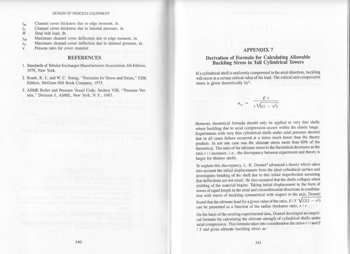
wYM
Ypv
1.
DESIGN OF PROCESS EQUIPMENT
Channel cover thickness due to edge moment, in.Channel cover thickness due to intemal pressure, in.Total bolt load, lbMaximum channel cover deflection due to edge moment, in.Maximum channel cover deflection due to intemal pressure, in.Poisson ratio for cover materia-
RDFERENCES
Standards of 'Ibbular Exchanger Manufacturers Association, 6th Rlition,1978, New York.
Roark, R. J., and W. C. Young, "Formulas for Stress and Strain," FifthEdition, McGraw-Hill Book Company, 1975.
ASME Boiler and hessure Vessel Code, Section VIII, "hessure Ves-sels," Division 1, ASME, New York, N.Y, 1983.
3.
3N 341
APPENDIX 7
Derivation of Formula for Calculating NlowableBuckling Stress in Tall Cylindrical Towers
If a cylindrical shell is uniforrnly compressed in the axial direction, buckling
will occur at a certain critical value of the load' The critical unit compressive
stress is given theoreticallY bYr:
,\,{r _;tEt
However. theoretical formula should only be applied to very thin shells
where buckling due to axial compression occurs within the elastic range'
Experiments with very thin cylindrical shells under axial pressure showed
tttat in at cases failure occurred at a shess much lower than the theory
predicts. ln not one case was the ultimate stress more than 607o of the
theoretical. The ratio of the ultimate stress to the theoretical decreases as the
ratio r / t increases, i.e., the discrepancy between experiment and theory is
larger for thinner shells.
To explain this discrepancy, L. H. Donnel2 advanced a theory which takes
into account the initial displacernents from the ideal cylindrical surface and
investigates bending of the shell due to this initial imperfection assuming
that deflections are not small. He also assumed that the shells collapse when
yielding of the material begins. Taking initial displacement in the form of
waves of equal length in the axial and circumferential directions in combina-
tion with waves oi buckling symmetrical with respect to the Tlr-8ryLfound that the ultimate load fora given value ofthe ratio, E/ I Vtz(t - 'z)can be presented as a function of the radius thickness ratio' r / t'
On the basis of the existing experimental data, Donnel developed an empiri-
cal formula for calculating the ultimate strength of cylindrical shells under
axial compression. This formula takes into consideration the ratios r / randE
/ I and gives ultimate buckling stress as:

DESIGN OF PR@ESS EQUIPMENT
" [o'u l-t'oY'
I + 0.004
(l+Neglecting the second tern in the numerator since it's very small comparedto .the first term, and using a factor of safety of 2. 14, we get the expression forallo$'able bucklins stress as:
;lE,,)
TNDEX
s= " E+A
dE
st
oocuk
(t + .oME tY)
.56tEd(r + .w4E tY)
NOMENCLATURE
Intemal lower diameter, in.Modulus of elasticity of tower material at operating temperarure , psi .
lnt€mal radius of tower, in.Allowable buckling stress for iower material, psi.Tower plate thickness, in.Yield point stress of lower material at operating temperatue, psi.Theoretical value of compressive stress, psi.Ultimaie buckling stress of tower, psi.Poisson ratio of to\ver material
REFERENCF^S
1. Timoshenko, S., "Theory of Elastic Stability," McGraw-Hill BookCompany Inc., New York, N.Y., 1936.
2. Donnel, L. H., "Results of Experirnents with Very Thin CylindricalShells Under Axial Plessure," ASME Tlans., Yol. 56, 1934.
Air coolers accessoriesfan. 288plenum, 288steam coil, 288structure.288
Air cooler's cover plate design, 302flange design, 302
Air cooler's headers, design, 290without partition or stiffener, 29'lwith single partition or stiffener,
293with two or more partitions and/or
stiffener, 295Air coolers headers, ty'pes
billet type, 287cover plate type, 286manifold type, 287plug type, 286
AL cooled heat exchangers, typesinduced draft, 281forced draft. 282
Air coolers tubes, typesbare,283double footed tension wrapped
finned,285edge wound tension wrapped
finned. 285
extruded finned, 284hot dipped solder bonded finned,
285single footed tension wrapped
finned,284tension wrapped embedded finned,
284Allowable shell buckling stress, 242Allowable stress in flange design
in hub of tapered flange, 83in loose type flange, 83radial in ring of flange, 83tangential in ring of flange, 83
Allowable stress in flanged and fluedexpansion joints
defection stress, 174pressure stress, 173total sfiess, 174
Allowable stress in pipe segmentexpansion joints
deflection stress, 189pressure stress, 189total shess, 189
Anchor bolt chair for support of tallstacks, 243
derivation of formulas. 321ASME Code
.N4 E rY)
342

lNl)l1XtNt)tix
flange design, 59types of circular flanges, 60,61,62
ASME Section VIII, Division Twoapplications, 231
comparison to Division One, 230
design criteria, 228introduction, 228limitations, 231
B class heat exchanger, definition, 21
Baffles, typesdisc and doughnut, 25,26orifice,26segmental,24
Base plate design for leg supPort,2r9
Bracing of leg supPolt, 219Bolt data, table, 70Bolt load, design, 69
Bolt spacing, maximum, 69Bottom plate design lor rectangular
tat|,ks,214Buckling of towers, derivation of
formula,34l
C class heat exchanger, definition, 2lCalculation forms for flange design
with full face gasket, 132
lap joint independent ring tYPe,
124slip on independent ring tYPe, 120
slip on or lap joint independenthub type, 128
weld neck dependent type, 114
weld neck independent tyPe, 116
weld neck with rib area, 112
Calculation forms for flange MAWPlap joint independent ring tYPe,
126slip on independent ring tYPe, 122
slip on or laP joint independenthub type, 130
weld neck independent tYPe, 118
Calculation form for ring tYPe
expansion joint design, 182
Checking strength ol'lcg support, 215
Class B heat exchanger, definition,2l
Class C heat exchanger, definition,2l
Class R heat exchanger, definition,2l
Concrete, allowable compressivestress, 244
Damping, definition, 236Damping of excessive vibration, 262Design of external bolting chairs for
stack support, 243Dimensions of steel pipe, 22Dynamic wind design for tall stacks,
244
Earthquake forces for vessels withbraced legs, 214
Earthquake forces for vessels withunbraced legs, 211
Exchanger (see heat exchanger)
fhcings, for gaskets, 64,65Fixed tubesheet design
miller's method, 161Flange, ASME circular types
integral,60,62Loose,60,62optional, 61,62
Flange design, ASME methoddeficiencies, 133
with full face gaskets, 106Flange sfiesses, maximum
axial hub stress, 83radial ring stress, 83tangential ring stress, 83
Flanged and flued expansion joints,allowable stress
deflection stress, 174pressure stress, 173
total stress, 174
Flanged and flued expanison joints,stress analysis
du( lo (lill.rctltilll llx)\crlrclll. l 7-
duc t0 intcrnal Prossulc, 172
Flat channel cover thickness'derivation of formula, 337
Floa(lng neaoexample design, 153
resultant stress, 150,151, 152
Floating head, shess analysis
due io extemal Pressure, 150
due to intemal Pressure, 149
Rrndamental frequencY of stack
vibration,238
Gasketscontact facings, 64,65factors, table for, 64,65material,64,65seating force, 63
seating stless, 64,65seating width, 66,67
Heat exchange! definition, 9Heat exchangeq shell and tube
classificationfixed{ubesheet tYPe, 17
floating-head tYPe, 18
inside iPlit backing-ring tYPe, l9outside-Packed lantem nng lYPe'
l8outside-Packed stuffing box tYPe,
18
pulhhrough bundle tYPe, 19
U-tube, 17
Heal exchanger. shell and tube design
ExamPle l, 28
ExamPle 2, 51
Heat ex&angel shell and tube
fabdcationbaffles, 24duplex tubes, 25'26ferrules, 27
flanges, 23
shells, 21
tube rolling, 27
tubes, 25
tubesheet and tube hole Pattem' 24
llcirt cxclrunScr. lunctlonschillcr,9condenseq l0cooler, l0final condenser, 10
forced circulation reboiler, l0exchanger, 10
heater, l0partial condenser, l0reboiler, l0steam generatot llsuperheater, 11
thermosiPhon reboiler, l0vaporizer, I Iwaste heat boiler, I I
Hub flange rotattondue to initial bolt tightening, 135
due to intemal Pressure, 136
due to unequal radial exPansion ot
the flange and shell, 138
methods oi reduction, 139,140
Hub of flange, ProPortioning, 69
lntegral flangeexample design, 86
Inrernal pressure formulas. derivation
ol 313
Le'g support, design foruxial loading, 215
combined loading, 216
eccentric loading, 215
wind or earthquake loading,216
Leg suppoil for vcrtical vessels 20T
Lu-g rupp.,n for |ertical vessels' 195
Map of seismic zones. 2 l2Map of wind Pressures, 208
Maximum allowable working pressure
for flanges, 100
Miller's met[od for fixed tubesheet
design, 161
Mode shapes for cantileveredcylinder,236
345344

INDEX
Natural frequency of vibration, 260Nomenclature of heat exchanger
components, 14
Pass rib area in flange design,84,85,86
Period of vibration, 235Pipe segment expansion joints,
allowable stressdeflection sffess, 189pressure stress, 189total stress, 189
Pipe segment expansion joints. stressanalysis
due to differential movement, 186
due to intemal pressure, 186
R class heat exchanger definition, 2lRectangular tank design
without stiffeners, 268with top edge stiffener 269with horizontal stiffeners, 271with vertical stiffenen, 272
Restrictions on using leg support,219
Resultant stressin floating head, 150,151,152
Ring expansion joint, typesflanged and flued head, 170flanged only head, 170flat plated with ring, 169
Ring flangeexample design, 97
Rotation of hub flangedue to initial bolt tightening, 135due to intemal pressure, 136due to unequal radial expansion of
the flange and shell, 138methods of reduction, 139,140
Seismic forces for stacks, 237Seismic zone map of the United
States,2l2Selection of approximate leg size,
2r0Stack frequency, affecting factors
gunite lining, 240base flexibility, 240
Standard flange specifications, 59,60
Stress analysis, of floating headsdue to extemal pressure, 150due to internal pressure, 149
Stress in vertical vesseldue to lug support, 198
Thickness of towers, derivation offormulas, 317
Tubsheet, derivation of equation,327 ,333
Type designation of heat exchangers,15
Vibration analysis of tall stacks ortowe$
Cantilever v ibrznon, 246,259ovaling vibration, 249
Von Karman vortex street for a stack,244
Vortex Shedding on a stack, 245
Wind forces for stacks, 233Wind forces for vessels
with braced legs, 214with unbraced legs, 207
Wind pressure map of the UnitedStates,208
Wind pressures as functions of heightabove ground, 209
346