Design of Perforated Plates
13
Journal of Engineering for Industry, Trans. ASME, Vol. 84, August, 1962 Paper No. 61-WA-llS W. J. O'DONNELL Associate Engineer, Westinghouse Bettis AtomicPowerlaboratory, Pittsburgh,Pa. Assoc.Mem.ASME B. F. LANGER ConsultingEngineer,WestinghouseBettis AtomicPowerlaboratory, Pittsburgh,Pa. FellowASME Design of Perforated Plates 1 This paper describes a method for calculating stresses and deflections in perJorated plates with a triangular penetration pattern. The method is based partly on theory and partly on experiment. Average ligament stresses are obtained from purely theoretical considerations but e.tfective elastic constants and peak stresses are derived from strain measurements and photoelast-ic tests. Acceptable limits for pressure stresses and ther- mal stresses in heat-exchanger tube sheets are also proposed. ----Nomenclature------------------------------ General Method ofAnalysis radial and tangential stresses in equivalent solid circular plate, psi 0' r or 0'0, whichever has largest absolute value, psi stresses in minimum ligament section, Fig. 7, psi (Continued on lIe.Tt paoe) co-ordinates shown in Figs. 7 and 8, in. width of plate rim, Fig. 13, in. minimum ligament width, Fig. 6, in. minimum ligament width for thin ligament at mis- drilled holes, in. outside radius of plate rim, Fig. 13, in. distance between center lines of perforations, Fig. 6', in. radius of perforations, Fig. 6, in. plate thickness, in. U T' (TO p H X, Y,Z b 2h 2hmin The general method of evaluating stresses and deflections in a perforated plate having a triangular penetration pattern is: Step 1. Calculate the nominal bending and membrane stresses and deflections of an equivalent solid plate having the effective modified elastic constants E* and p* and the same dimensions as the perforated plate. Step 2. Calculate physically meaningful perforated-plate stress values from the nominal stress values in the equivalent solid plate from Step 1. Deflections of the perforated plate are the same as the deflections of the equivalent solid plate. "Yhen the perforated plate is part of a structure, as in the case of a heat exchanger, Step 1 is accomplished using classical structural-analysis methods. A study of the effective elastic con- stants for use in Step 1 is contained herein, and values based on ficiency of 20 per cent, as specified in Par. R-2.5 of reference [11]. 'When service conditions are usually severe or when the utmost is desired in reliability and optimum design, stresses should be cal- culated in detail and realistic allowable stress values should be set. It is the realization of this fact that led to the previous work and the work described in this paper. Most of the proposed methods for analyzing perforated plates have involved the concept of an "equivalent" solid plate [3, 4]. In one method the equivalent solid plate has the same dimensions as the actual plate but its flexural rigidity is reduced by a factor called its defleetion efficiency. In another method the equivalent plate is also the same as the solid plate, but it has fictitious elastic constants E* and p* in place of the actual constants of the material E and P. The latter concept is used in this paper. Stresses 1 This work is part of a dissertation suhmitted by W. J. O'Donnell to the University of Pittsburgh in partial fulfillment of the require- ments for the degree of Doctor of Philosophy. 2 Numbers in brackets designate References at end of paper. 3 See, for example, reference [11],paragraphs R-7.122 and R-7.123. Contributed by the Petroleum Division for presentation at the Winter Annual Meeting, New York, N. Y., November 26-December 1, 1961, of THEAMERICANSOCIETY OF lvIECHANICAL ENGINEERS. Manuscript received at ASME Headquarters, July 26, 1961. Paper No. 61-WA-115. Material Properties D* E* H3/12 (1 - p*2), effective flexural rigidity of per- forated plate, lb-in. E elastic modulus of solid material, psi E* effective elastic modulus of perforated material, psi Sm - allowable membrane stress intensity of material, psi p Poisson's ratio of material, dimensionless p* effective Poisson's ratio for perforated material, dimen- sionless Pp Poisson's ratio of plastic-model material, dimensionless Pp * effective elastic modulus of perforated plastic models, di- mensionless OiT thermal expansion coefficient, in/in deg F Introduction TIm calculation of stresses in perforated plates is a subject which has received considerable attention as a result of the widespread use of flat tube sheets in heat-exchange equip- ment. Major contributions have been made by Horvay [1, 2],2 Malkin [3], Gardner [4, 5, 6], Duncan [7], Miller [8], Galletly and Snow [9], and Salerno and Mahoney [10]. Most of the pub- lished work has been limited to perforations arranged in an equilateral triangular pattern, and the present paper is no excep- tion. The Pressure Vessel Research Committee of the Welding Research Council is currently sponsoring work on square pat- terns of holes but no results are available as yet. Most heat-exchanger tube sheets are designed to meet the standards set by the Tubular Exchanger Manufacturers Associa- tion [11]. In these TEMA standards the thickness required to resist shear depends on the ligament efficiency of the perfora- tions, but the thickness required to resist bending is independent of ligament efficiency. S This does not mean, of course, that bending stress is not affected by ligament efficiency; it does mean, however, that all tube sheets designed to TEMA standards are designed to be safe with the minimum allowable ligament ef- Co-ordinatesand Dimensions l' = radial distance of ligament from center of circular per- forated plate, in. Discussion on this paper will be accepted at ASME Headquarters until January 10, 1962
-
Upload
scribduserbest -
Category
Documents
-
view
404 -
download
14
Transcript of Design of Perforated Plates
Journal of Engineering for Industry,Trans. ASME, Vol. 84, August, 1962
Paper No.61-WA-llS
W. J. O'DONNELLAssociate Engineer, Westinghouse Bettis
AtomicPower laboratory, Pittsburgh,Pa.Assoc.Mem.ASME
B. F. LANGERConsultingEngineer,WestinghouseBettisAtomicPower laboratory, Pittsburgh,Pa.
FellowASME
Design of Perforated Plates 1
This paper describes a method for calculating stresses and deflections in perJoratedplates with a triangular penetration pattern. The method is based partly on theory andpartly on experiment. Average ligament stresses are obtained from purely theoreticalconsiderations but e.tfective elastic constants and peak stresses are derived from strainmeasurements and photoelast-ic tests. Acceptable limits for pressure stresses and ther-mal stresses in heat-exchanger tube sheets are also proposed.
----Nomenclature------------------------------
GeneralMethodofAnalysis
radial and tangential stresses in equivalent solidcircular plate, psi
0'r or 0'0, whichever has largest absolute value, psistresses in minimum ligament section, Fig. 7, psi
(Continued on lIe.Tt paoe)
co-ordinates shown in Figs. 7 and 8, in.width of plate rim, Fig. 13, in.minimum ligament width, Fig. 6, in.minimum ligament width for thin ligament at mis-
drilled holes, in.outside radius of plate rim, Fig. 13, in.distance between center lines of perforations, Fig. 6',
in.radius of perforations, Fig. 6, in.plate thickness, in.
U T' (TO
pH
X, Y,Zb
2h2hmin
The general method of evaluating stresses and deflections in aperforated plate having a triangular penetration pattern is:
Step 1. Calculate the nominal bending and membrane stressesand deflections of an equivalent solid plate having the effectivemodified elastic constants E* and p* and the same dimensions asthe perforated plate.
Step2. Calculate physically meaningful perforated-plate stressvalues from the nominal stress values in the equivalent solid platefrom Step 1. Deflections of the perforated plate are the same asthe deflections of the equivalent solid plate.
"Yhen the perforated plate is part of a structure, as in the caseof a heat exchanger, Step 1 is accomplished using classicalstructural-analysis methods. A study of the effective elastic con-stants for use in Step 1 is contained herein, and values based on
ficiency of 20 per cent, as specified in Par. R-2.5 of reference [11].'When service conditions are usually severe or when the utmost isdesired in reliability and optimum design, stresses should be cal-culated in detail and realistic allowable stress values should beset. It is the realization of this fact that led to the previous workand the work described in this paper.
Most of the proposed methods for analyzing perforated plateshave involved the concept of an "equivalent" solid plate [3, 4].In one method the equivalent solid plate has the same dimensionsas the actual plate but its flexural rigidity is reduced by a factorcalled its defleetion efficiency. In another method the equivalentplate is also the same as the solid plate, but it has fictitious elasticconstants E* and p* in place of the actual constants of thematerial E and P. The latter concept is used in this paper.
Stresses
1 This work is part of a dissertation suhmitted by W. J. O'Donnellto the University of Pittsburgh in partial fulfillment of the require-ments for the degree of Doctor of Philosophy.
2 Numbers in brackets designate References at end of paper.3 See, for example, reference [11],paragraphs R-7.122 and R-7.123.Contributed by the Petroleum Division for presentation at the
Winter Annual Meeting, New York, N. Y., November 26-December1, 1961, of THE AMERICANSOCIETYOF lvIECHANICALENGINEERS.Manuscript received at ASME Headquarters, July 26, 1961. PaperNo. 61-WA-115.
Material PropertiesD* E* H3/12 (1 - p*2), effective flexural rigidity of per-
forated plate, lb-in.E elastic modulus of solid material, psi
E* effective elastic modulus of perforated material, psiSm - allowable membrane stress intensity of material, psi
p Poisson's ratio of material, dimensionlessp* effective Poisson's ratio for perforated material, dimen-
sionlessPp Poisson's ratio of plastic-model material, dimensionless
Pp * effective elastic modulus of perforated plastic models, di-mensionless
OiT thermal expansion coefficient, in/in deg F
IntroductionTIm calculation of stresses in perforated plates is a
subject which has received considerable attention as a result ofthe widespread use of flat tube sheets in heat-exchange equip-ment. Major contributions have been made by Horvay [1, 2],2Malkin [3], Gardner [4, 5, 6], Duncan [7], Miller [8], Galletlyand Snow [9], and Salerno and Mahoney [10]. Most of the pub-lished work has been limited to perforations arranged in anequilateral triangular pattern, and the present paper is no excep-tion. The Pressure Vessel Research Committee of the WeldingResearch Council is currently sponsoring work on square pat-terns of holes but no results are available as yet.
Most heat-exchanger tube sheets are designed to meet thestandards set by the Tubular Exchanger Manufacturers Associa-tion [11]. In these TEMA standards the thickness required toresist shear depends on the ligament efficiency of the perfora-tions, but the thickness required to resist bending is independentof ligament efficiency. S This does not mean, of course, thatbending stress is not affected by ligament efficiency; it does mean,however, that all tube sheets designed to TEMA standards aredesigned to be safe with the minimum allowable ligament ef-
Co-ordinatesand Dimensionsl' = radial distance of ligament from center of circular per-
forated plate, in.
Discussion on this paper will be accepted at ASME Headquarters until January 10, 1962
experimcntal results by Sampson are recommended. Methods ofevaluating average and peak ligament stresscs for Step 2 of theanalysis are developed and appropriate design limits are recom-mended for these values. A method of evaluating the accepta-bility of misplaced holes is also given.
Effective Elastic Constants for Perforated PlatesWhen a perforated plate is used as a part of a redundant struc-
ture, the values used for the effective elastic constants will affectcalculated stresses in the remainder of the structure, as well as inthe perforated plate itself. For example, the amount of rota-tion at the periphery of a steam-generator tube sheet depends onthe relative rigidity or the tube sheet with respect to the rest ofthe heat exchanger. If effective elastic constants (particularlyE*) which are too low are used in the analysis, the theoreticalrotation at the periphery of the tube sheet due to pressure loadsacross the tube sheet will be greater than the actual rotation. Thecalculated stresses at the periphery will then be lower than theactual stresses. This can be seen from fig. 29 of reference [12].Correspondingly, if an effective elastie modulus which is too highis used in the analysis, the calculated pressure stresses at thecenter of the tube sheet would be low. If the tube sheet is takento be too rigid, the calculated stresses, due to a pressure dropacross the tube sheet, in the head and shell at their junction ",;ththe tube sheet would be lower than the actual stresses. Sincestresses in these areas are usually among the highest stresses in aheat exchanger, it is important that they be evaluated properly.
Taking the tube sheet to be too flexible causes calculated ther-mal-stress values in the tube sheet and in the remainder of theheat exchanger to be below the actual stress values.
From the foregoing discussion it may be concluded that it is notpossible to insure conservatism in heat-exchanger or tube-sheetstress calculations by assuming effective elastic constants whichare known to be either too high or too low. The best estimates ofp* and E*, rather than the highest or lowest estimates should beused.
Many different sets of effective elastic constants for perforatedmaterials having a triangular penetration pattern have beenproposed. Five of the best known sets of values have been ob-tained from theoretical considerations and two have beenobtained experimentally:
1 Theoretical Horvay plane stress [1].2 Theoretical Horvay bending [2].3 Theoretical modified Horvay bending, corrected for con-
strained warping by Salerno and Mahoney [10].4 Theoretical Malkin bending [3].
5 Theoretical modified Malkin bending corrected for COIl-
strained warping by Salerno and Mahoney [10].6 Experimental Sampson plane stress []3].7 Experimental Sampson bending [13].
The "plane-stress" constants apply to loads in the plane of theperforated plate; i.e., tensile or compressive loads as opposed tobending. Allof the theoretieal values for E* and p* were intendedto apply only to those perforated materials having ligamentsthinner than those usually found in tube sheets. For example,Horvay recommends his theory only for ligament efficiencieslessthan 20 per cent.
Sampson Effective Elastic ConstantsThe Sampson experimental values of the effective elastic con-
stants for both plane stress and bending loads were obtainedin tests on rectangular coupons at the ~T estinghouse ResearchLaboratories. The test specimens were made of plastic material,p = 0.5. Subsequent tests were run to evaluate the effect of thematerial Poisson's ratio on the values for the effective elastic con-stants. Plane-stress constants were obtained by applying uni-axial tensile loads, and bending constants were obtained by apply-ing pure bending loads. These values were found to differ quitemarkedly from the theoretical values.
The validity of the general method of using effective elasticconstants and stress multipliers to calculate stresses and de-flections in tube sheets was checked by Leven in tests on per-forated circular plates [14, ]5]. The plates were made of plastic(p = 0.5) and were simply supported and uniformly loaded.Plate deflections were measured and ligament stress variationsalong radial sections were obtained. The results give supportto the validity of the Sampson experimental method of determin-ing the effective elastic constants using perforated rectangularcoupons subject to uniaxial loads. The measured deflectionsagreed best with those calculated using the effective elastic con-stants obtained experimentally by Sampson. Moreover, themeasured local stresses agreed closely "ith those calculated usingthe stress-ratio factors obtained by Sampson. Hence, the Samp-son effective elastic constants are considered to be the mostaccurate for use in design calculations.
The Sampson effective elastic constants for relatively thinplates in bending differ significantly from those in plane stress.However, as a plate in bending gets thicker, the stress gradientthrough the depth gets smaller and it is reasonable to expect thata very thick plate would not be affected appreciably by the smallstress gradient in the thickness direction. Consequently, the
----N0menclature'----------------------------Kr value given in Fig. 13K", value given in Fig. 15Ku value given in Fig. 10 for {3= 0
Y valuegiveninFig.]2
Others
F normal force carried uy ligament, Fig. 6, lb/in.11 shear force carried by ligament, Fig. 6, lb/in.
111 moment carried by ligament, Fig. 6, in-lb/in.P pressure on plate surface under consirleration, psi
I1P pressure drop across tube-sheet, psiT p temperature at primary tube-sheet, surface, deg FTs temperature at secondary tube-sheet surface, deg FTIl temperature of hot side of tube sheet, Fig. 14, deg FTc temperature of cold side of tube sheet, Fig. 14, deg Ff3 (jr/(jO or (jO/(jr whichever gives -1 <: f3 <: 1, dimen-
sionlessIf angular orientation of ligament, Fig. 7, radians
stresses averaged through depth of plate, psi
(jeer
(Jrim
U"max
Seer
transverse shear stress averaged through depth ofplate, psi
nominal bending plus membrane stress at insideof rim, psi
maximum principal stress basecI on averagestresses across minimum ligament section, psi
stress intensity based on stresses averaged acrossminimum ligament section at plate surface, psi
maximum local stress, psistress intensity based on stresses averaged across
minimum ligament section and through depthof plate, psi
Stress Multipliers (dimensionless)K value given in Fig. 10
Kn = value given in Fig. 14
i1:u 0"11' T1/X'ur,uo
2 Transactions of the AS M IE
40 60 80100204 6 8 10H/R
20.4 0.6 0.8 I
I I I I I I I I
1-
~
'"h 1 '\
=R 3 "tJ"
IIPLANE STRESS -=< I-
h .1.--, ""'- .......••. 1\R = 4
H = DEPTH OF PLATE2R = PITCH OF TRIANGULAR HOLE PATTERN2h = MINIMUM LIGAMENT WIDTH
I I I II I I I I I I I I I I Io0.2
0.1
0.6
0.2
0.3
E*/E
0.4
0.5
Fig.' Variation of Sampson effective elastic modulus with depth of a plate in bending (vp = 0.5Poisson's ratio of solid material)
I , I
IH = ~EPTH IOF IpLATE' I I'I
I
2R = PITCH OF TRIANGULAR HOLE PATTERN
2h = MINIMUM LIGAMENT WIDTH
h IR = 4"--"" V- /,..- r- tf
/ ~ II -...r- -Lr lih I PLANE STRESS -~ R . 3
~,..
I I
10
0.8
0.6
v*
0.4
0.2
o0.2 0.4 0.6 0.8 I 2 4
H/R6 8 10 20 40 60 80100
Fig. 2 Variation of Sampson effective Poisson's ratio with a depth of a plate in bending (vp = 0.5= Poisson's ratio of solid material)
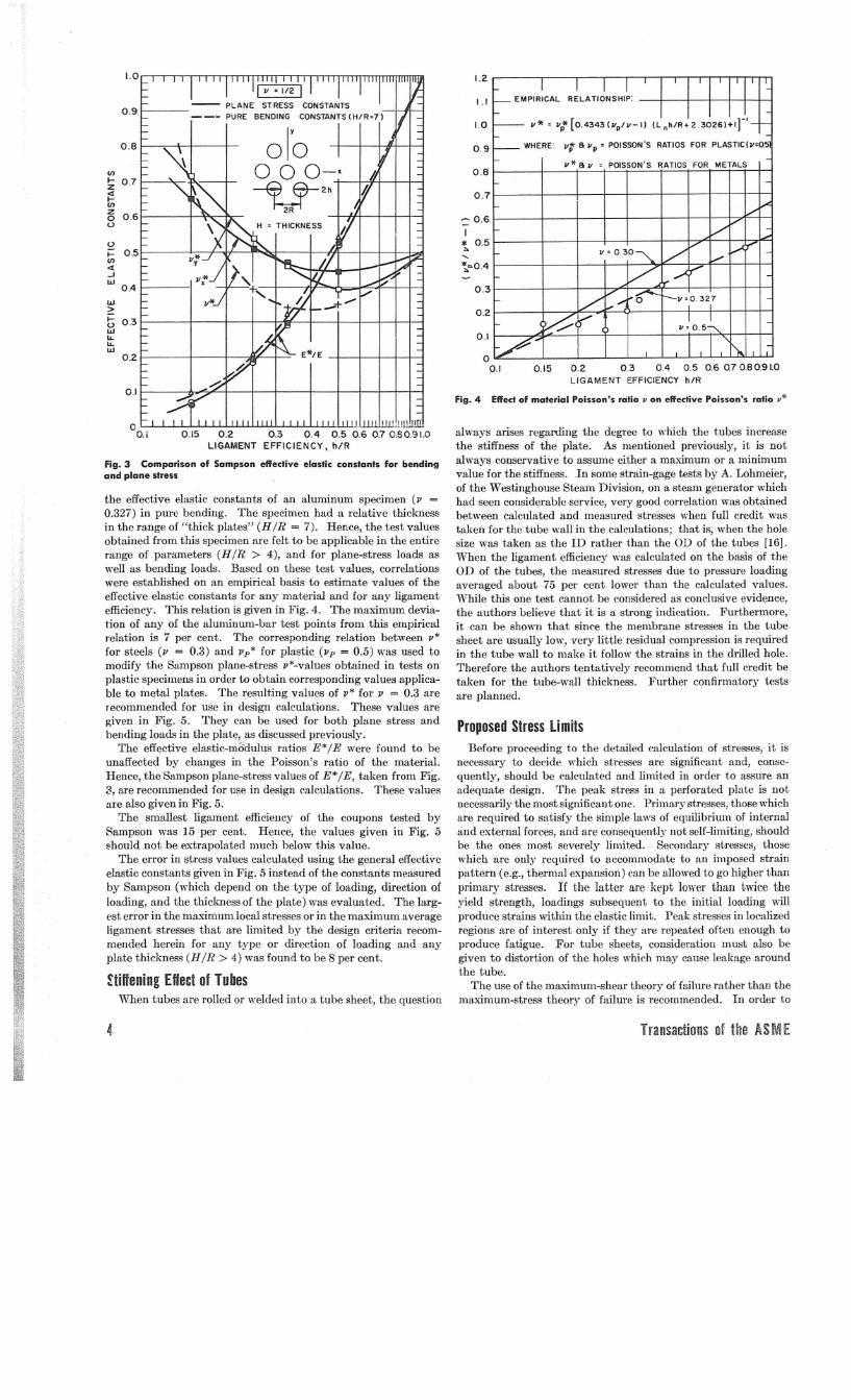
values for the effective elastic constants for a plate in bendingshould approach the plane stress values as the plate gets thick.Fig. 1 shows the variation of E* with the relative thickness of aplate in bending, and Fig. 2 shows the same variation for /1*.
Note the rather abrupt transition in the E* IE-values that occurin the vicinity of H IR = 4. This appears to be what might beinterpreted as a transition region between "thick" and "thin"perforated plates.
Obviously, it would be inconvenient to use one set of elasticconstants for bending loads and another set for in-plane loads.Fortunately, this is not necessary as long as the plate is thickerthan about twice the pitch of the perforations (Hill> 4) andthis situation occurs in most heavy-duty heat-exchange equip-ment which requires the refined analysis described here. Theeffective elastic cOllstants in bending for H IR > 4 do not differgreatly from the plane-stress values. Fig. 3 shows the bendingconstants at Hill = 7 plotted with the uniaxial plane-stress con-stants. Accordingly, the plane-stress constants appear to be the
most acceptable values for plates having a relative thicknes8HIR> 4.
Notice that the uniaxial plane-stress values of effective Pois-son's ratios (/1",* and /Iv *) vary with the orientation of the loadwith respect to the hole pattern. The impracticality of factoringthis anisotropic behavior into the analysis is immediately evi-dent, and values must be used which represent the approximatePoisson's effect in all directions. This is not considered to be aserious problem, however, partly because the principal strel:iSesare generally not oriented in the directions resulting in the largestdifferences between the effective Poisson's ratios (the x and y-directions, respectively, in Fig. 3), and partly because these dif-ferences do 1I0thave a large effeet on the calculated stresses.
Sampson evaluated the effective elastic constants for perforatedplastic materials (/lp = 0.5) over a wide range of ligament ef-ficiencies under bending and plane-stress loads. He then pro-ceeded to evaluate the effect of material Poisson's ratio on theeffective elastic constants. This was accomplished by measuring
Journal of Engineering for Indllstry 3
4 Transactions of the AS !ViE
Before proceeding to the detailed calculation of stresses, it isnecessary to decide which stresses are significant and, conse-quently, should be calculated and limited in order to assure anadequate design. The peak stress in a perforated plate is notnecessarily the most significant one. Primary stresses, those whichare required to satisfy the simple laws of equilibrium of internaland external forces, and are consequently not self-limiting, shouldbe the ones most severely limited. Secondary stresscs, thosewhich are only required to accommodate to an imposed strainpattern (e.g., thermal expansion) can be allowed to go higher thanprimary stresses. If the latter are kept lower than twice theyield strength, loadings subsequent to the initial loading willproduce strains within the elastic limit. Peak stresses in localizedregions are of interest only if they are repeated often enough toproduce fatigue. For tube sheets, consideration must also begiven to distortion of the holes which may cause leakage aroundthe tube.
The use of the maximum-shear theory of failure rather than them(lximum-st,ress theory of failure is recommended. In order to
Proposed Stress Limits
0.1
1.2
0.2
1.1
1.0 p*: vt[O.4343(VpIV-11 (Lnh/R+2.3026l+lr'
0.9 WHERE: vt 6 vp = POISSON'S RATIOS FOR PLASTIC(v:O.5
v* 6v : POISSON'S RATIOS FOR METALS
0.3
0.15 0.2 0.3 0.4 0.5 0.60.70.80.91.0LIGAMENT EFFICIENCY h/R
~ 0.6
I* 0.5
"-"-*,."0.4
0.7
0.8
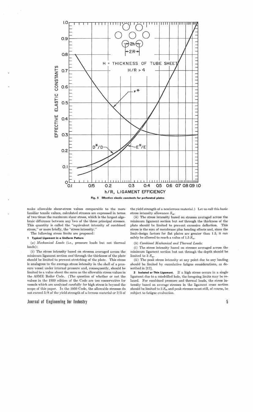
always arises regarding the degree to which the tubes increasethe stiffness of the plate. As mentioned previously, it is notalways conservative to assume either a maximum or a minimumvalue for the stiffness. In some strain-gage tests by A. Lohmeier,of the 'Vestinghouse Steam Division, on a steam generator whichhad seen considerable service, very good correlation was obtainedbetween calculated and measured sti'esses when full credit wastaken for the tube wall in the caleulations; that is, when the holesize was taken as the ID rather than the OD of the tubes [16].When the ligament effic.iencywas calculated on the basis of theOD of the tubes, the measured stresses due to pressure loadingaveraged about 75 per cent lower than the calculated values.While this one test cannot be considered as conclusive evidence,the authors believe that it is a strong indication. Furthermore,it can be shown that sinee the membrane stresses in the tubesheet are usually low, very little residual compression is requiredin the tube wall to make it follow the strains in the drilled hole.Therefore the authors tentatively recommend that fuJI credit betaken for the tube-wall thickness. Further confirmatory testsare planned.
Fig.4 Effect of material Poisson's ratio II on effective Poisson's ratio v*
E*/E
.!!I'I0.15 0.2 0.3 0.4 0.5 0.6 0.70.50.91.0
LIGAMENT EFFICIENCY, h/R
1.0
0.9
0.8 olYoV> o 0 o-x•... 0.7Z
~2h<l•...V>Z 2R0 0.6u
U
I- 0.5V><l...Jw
0.4
LoJ
~I- 0.3uwll..ll..LoJ
0.2
0.1
00.1
the effective elastic constants of an aluminum specimen (II =0.327) in pure bending. The specimen had a relative thicknessin the range of "thick plates" (H IR = 7). Hence, the test valuesobtained from this specimen are felt to be applicable in the entirerange of parameters (HIR > 4), and for plane-stress loads aswell as bending loads. Based on these test values, correlationswere established on an empirical basis to estimate values of theeffective elastic constants for any material and for any ligamentefficiency. This relation is given in Fig. 4. The maximum devia-tion of any of the aluminum-bar test points from. this empiricalrelation is 7 per cent. The corresponding relation between p*
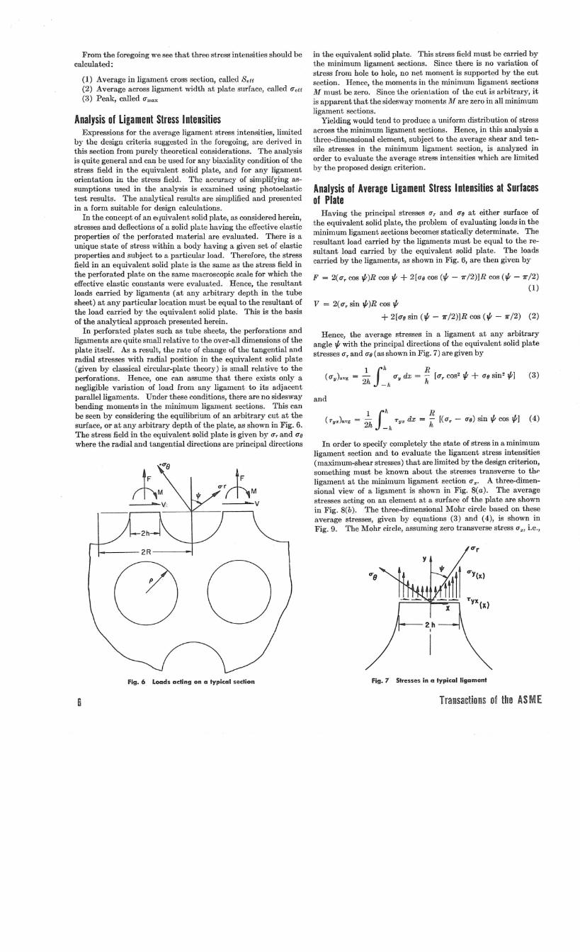
for steels (II = 0.3) and IIp* for plastic (lip = 0.5) was used tomodify the Sampson plane-stress II*-values obtained in tests onplastic specimens in order to obtain corresponding values applica-ble to metal plates. The resulting values of 11* for II = 0.3 arerecommended for use in design calculations. These values aregiven in Fig. 5. They can be used for both plane stress andbending loads in the plate, as discussed previously.
The effective elastic-madulus ratios E* IE were found to beunaffected by changes in the Poisson's ratio of the material.Hence, the Sampson plane-stress values of E* IE, taken from Fig.3, are recommended for use in design calculations. These valuesare also given in Fig. 5.
The smallest ligament efficiency of the coupons tested bySampson was 15 per cent. Hence, the values given in Fig. 5~hould not be extrapolated much below this value.
The error in stress values calculated using the general effectiveelastic constants given in Fig. 5 instead of the constants measuredby Sampson (which depend on the type of loading, direction ofloading, and the thickness of the plate) was evaluated. The larg-est error in the maximum local stresses or in the maximum averageligament stresses that are limited by the design criteria recom-mended herein for any type or direction of loading and anyplate thickness (HIR > 4) was found to be 8 per cent.
Wffening Effect of TubesWhen tubes are rolled or welded into a tube sheet, the question
Fig. 3 Comporison of Sompson effective elostic constants for bendingand plane stress
0.2 0.3 0.4 0.5 0.6 0.7 0.80.9 1.0h/R, LIGAMENT EFFICIENCY
0.15o
0./
0.1
0.8
H = THICKNESS OF(/)I- 0.7 H /R > 4zj:!(/)z0 0.6uuI-en 0.5<t.-JW
W> 0.4I-uWlJ..lJ.. 0.3w
D*/D E*/E0.2
0.9
1.0
Fig. 5 Effective elastic constants for perforated plates
make allowable shear-stress values comparable to the morefamiliar tensile values, calculated stresses are expressed in termsof two times the maximum slWar stress; which is the largest alge-braic difference between any"two of the three principal stresses.This quantity is called the "equivalent intensity of combinedstress," or more briefly, the "stress intensity."
The following stress limits are proposed:1 Typical Ligament in a Uniform Pattern
(a) llfechanical Loads (i.e., pressure loads but not thermalloads):
(i) The stress intensity based on stresses averaged across theminimum ligament section and through the thickness of the plateshould be limited to prevent stretching of the plate. This stressis analogous to the average stress intensity in the shell of a pres-sure vessel under internal pressure and, consequently, should belimited to a value about t.he same as the allowable stress values int.he ASME Boiler Code. (The quest.ion of whether or not thevalues in t.he 1959 edition of t.he Code are t.oo conservative forvessels which are analyzed carefully for high stress is beyond thescope of this paper. In t.he 1959 Code, the allowable stresses donot exceed 5/8 of the yield strength of a ferrous material or 2/3 of
the yield strength of a nonferrous material.) Let us call thi~ basicst.ress intensity allowance Sm.
(ii) The stress intensity based on stresses averaged across theminimum ligament section but not through the thickness of theplate should be limited to prevent excessive deflection. Thisstress is the sum of membrane plus bending effects and, since thelimit-design factors for flat plates are greater t.han 1.5, it cansafely be allowed to reach a value of 1.5 Sm.
(b) Combined ilfechani-eal and Thermal Loads:(i) The stress intensity based on stresses averaged across the
minimum ligament section but not through the depth should belimited to 3 Sm.
(ii) The peak stress intensity at any point due to any loadingshould be limited by cumuintivc fatigue considerations, as de-scribed in [17].
2 Isolated or Thin Ligament. If a high stress occurs in a singleligament due to a misdrilled hole, the foregoing limits may be re-laxed. For combined pressure and thermal loads, the stress in-tensity based on average stresses in the ligament cross seet-ionshould be limited to 3 S", and peak stresses must. still, of course, besubject to fatigue evaluation.
Journal of Engineering tor Industry 5
F = 2(rrT cos I/;)R cos I/; + 2[lIo cos (I/; - 7l"/2)]R cos (I/; - 7l"/2)(1)
Analysis of Average Ligament Stress Intensities at Surfacesof Plate
(4)
(3)1 flL R- rr dx = - [rr cos2 I/; + IIO sin2 1/;]2h -IL y h T
1 flL R(Tyz).Vg = - Tyz dx = - [(rrT - rro) sin I/; cos 1/;]
2h -IL h
and
In order to specify completely the state of stress in a minimumligament section and to evaluate the ligament stress intensities(maximum-shear stresses) that are limited by the design criterion,something must be known about the stresses transverse to th"ligament at the minimum ligament section rrx' A three-dimen-sional view of a ligament is shown in Fig. 8(a). The averagestresses acting on an element at a surface of the plate are shownin Fig. 8(b). The three-dimensional Mohr circle based on theseaverage stresses, given by equations (3) and (4), is shown inFig. 9. The Mohr circle, assuming zero transverSe stress rrx, i.e.,
Hence, the average stresses in a ligament at any arbitraryangle I/; ,,·;th the principal directions of the equivalent solid platestresses rrTand rro (as shown in Fig . .7)are given by
v = 2(rrT sin I/;)R cos I/;+ 2[rro sin (I/; - 7l"/2)]R cos (I/; - 7l"/2) (2)
in the equivalent solid plate. This stress field must be carried bythe minimum ligament sections. Since there is no variation ofstress from hole to hole, no net moment is supported by the cutsection. Hence, the moments in the minimum ligament sectionsM· must be zero. Since the orientation of the cut is arbitrary, itis apparent that the sidesway moments III are zero in all minimumligament sections.
Yielding would tend to produce a uniform distribution of stressacross the minimum ligament sections. Hence, in this analysis athree-dimensional element, subject to the average shear and ten-sile stresses in the minimum ligament section, is analyzed inorder to evaluate the average stress intensities which are limitedby the proposed design criterion.
Having the principal stresses lIT and rro at either surface ofthe equivalent solid plate, the problem of evaluating loads in theminimum ligament sections becomes statically determinate. Theresultant load carried by the ligaments must be equal to the re-sultant load carried by the equivalent solid plate. The loadscarried by the ligaments, as shown in Fig. 6, are then given by
From the foregoing we see that three stress intensities should becalculated:
(1) Average in ligament cross section, called Serr(2) Average across ligament width at plate surface, called rrerr(3) Peak, called rrmax
Analysis of Ligament Stress IntensitiesExpressions for the average ligament stress intensities, limited
by the design criteria suggested in the foregoing, are derived inthis section from purely theoretical considerations. The analysisis quite general and can be used for any biall.;ality condition of thestress field in the equivalent solid plate, and for any ligamentorientation in the stress field. The accuracy of simplifying as-sumptions used in the analysis is examined using photoelastictest results. The analytical results are simplified and presentedin a form suitable for design calculations.
In the concept of an equivalent solid plate, as considered herein,stresses and deflections of a solid plate having the effective elasticproperties of the perforated material are evaluated. There is aunique state of stress within a body having a given set of elasticproperties and subject to a particular load. Therefore, the stressfield in an equivalent solid plate is the same as the stress field inthe perforated plate on the same macroscopic scale for which theeffective elastic constants were evaluated. Hence, the resultantloads carried by ligaments (at any arbitrary depth in the tubesheet) at any particular location must be equal to the resultant ofthe load carried by the equivalent solid plate. This is the basisof the analytical approach presented herein.
In perforated plates such as tube sheets, the perforations andligaments are quite small relative to the over-all dimensions of theplate itself. As a result, the rate of change of the tangential andradial stresses with radial position in the equivalent solid plate(given by classical circular-plate theory) is small relative to theperforations. Hence, one can assume that there exists only anegligible variation of load from any ligament to its adjacentparallel ligaments. Under these conditions, there are no sideswaybending moments in the minimum ligament sections. This canbe seen by considering the equilibrium of an arbitrary cut at thesurface, or at any arbitrary depth of the plate, as shown in Fig. 6.The stress field in the equivalent solid plate is given by rrT and rrowhere the radial and tangential directions are principal directions
Fig. 6 Loads aeling on a typical seelion Fig. 7 Stresses in a typical ligament
6 Transactions of the AS M [
Ix I
\II
A/ "/ \
// ,,,/ \
"
z
(b) AVERAGE STRESSES AT PRIMARY
OR SECONDARY SURFACE
(0) 3- DIMENSIONAL VIEW OF LIGAMENT (e) AVERAGE STRESSES AVERAGED
THROUGH DEPTH
Fig. 8 Three-dimensional stresses
ACTUAL STRESSES IN PLANE OFTUBE SHEETACTUAL STRESSES IN PRINCIPALTRANSVERSE PLANESCALCULATED STRESSES IN PLANE OFTUBE SHEET ASSUMING PLANE STRESS..
tT
\\\
"-( O,'t"yx) --- :::--(CTX,"yX)--
Fig. 9 Three-dimensional Mohr circle for stresses averaged acrossminimum ligament section at su;:face of perforated plate
plane stress, is also shown for the plane of maximum shear. Forpurposes of this analysis, the transverse stresses 0"x will be takenequal to zero. The significance of this important assumption willbe explained subsequently. The corresponding maximum princi-pal stress, based on the average value of the stresses across theminimum ligament section, is given by
~ {O"r cos21/; + 0"0 sin2 if;h 2
The comparable expression for the stress intensity (twice themaximum shear stress) in the minimum ligament section is givenby
where (J"cff is the stress intensity limited by the design criterion.Equation (6) gives the stress intensity based on the average
stress across any particular minimum ligament section for anyligament orientation if; at either surface of the plate.
Consider the significance of assuming a zero transverse stressat the minimum ligament section. Obviously, the transversestress must be zero at the edges of the minimum ligament section.Moreover, this stress is usually small, even at the center of theligament. Photoelastic tests [18] have shown that the averagetransverse stress usually has the same sign as the average longi-tudinal stress, as shown in Fig. 9. When these stresses have thesame sign, the calculated value of the stress intensity in the planeof the plate, based on stresses averaged across the minimumligament section, will always be equal to or greater than thecorrect value of the stress intensity in that plane. This is il-lustrated in Fig. 9.
There are conditions for which the maximum shear does notoccur in the plane of the plate. This happens when the minimumprincipal stress in the plane of the plate has the same sign as themaximum principal stress in that plane (the transverse shearstresses being zero at the surfaces). The maximum shear can thenbe found by rotat.ing the element in the principal plane perpen-dicular t.o the plat.e because t.he difference bet.ween the maximumprincipal st.ress and the zero Z-direction stress' is great.er t.hant.he difference between any other principal stresses. However,the maximum shear st.resses in t.he plane of t.he plate calculated by
J'h}+ (O"T - 0"0)2 COS2 if; sin2 if;
Journal of Engineering for Industry
, Thc Z-dircction stress due to pressure acting at the surface of aplate is attenuated a short distance from the surface in the manner ofa bearing stress. Hence, although this stress should be considered inthe fatigue analysis of local peak stresses, it need not be considered in
(5) the average stress-intensity limitations because the latter are onlyintended to prevent excessiveyielding and deformation.
7
where
Analysis of ligament Stress Intensities Averaged ThroughDepth of Plate
The value of (T, averaged through the depth of a plate at anylocation is equal to the value of 00 averaged through the depth atthat location. Moreover, these average values do not vary withlocation in a symmetrically loaded circular plate because theyare produced by membrane-type loads. From equation (4), theaverage shear stress in the plane of the plate due to membrane
(8)
(T off =
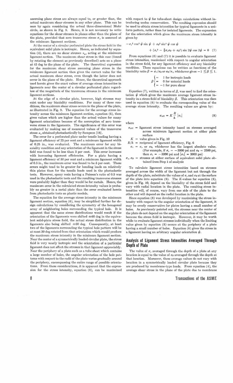
KR/h
ligament stress intensity based on stresses averagedacross minimum ligament section at either platesurface
value given in Fig. 10reciprocal of ligament efficiency, Fig. 6a, or (To, whichever has the largest absolute value.
(For example, if (T, = -3000 psi and (To = 2500 psi,then (T, = -3000 psi and /(T,j = 3000 psi)
stresses at either surface of equivalent solid plate ob-tained from Step 1 of analysis
To calculate ligament stress intensities based on stressesaveraged across the \\idth of the ligament but not through thedepth of the plate, substitute the values of (T, and (TOat the surfaceof the plate into equation (8). The K-values for equation (8),given in Fig. 10, depend on the biaxiality of the stress field andvary with radial location in the plate. The resulting stress in-tensities will, of course, vary from one side of the plate to theother and will depend on the radial location in the plate.
Since equation (8) was developed by maximizing the stress in-tensity with respect to the angular orientation of the ligament, itmay be overly conservative for plates having a small number ofholes. As previously pointed out, the stresses near the center ofthe plate do not depend on the angular orientation of the ligamentbecause the stress field is isotropic. However, it may be worthwhile to evaluate ligament stresses individually when the limitingvalue given by equation (8) occurs at the periphery of a platehaving a small number of holes. Equation (6) gives the stress ina ligament having an arbitrary angular orientation if;.
with respect to if; for tube-sheet design calculations without in-troducing undue conservatism. The resulting expression shouldbe used to obtain stress inteusities for typical ligaments in a uni-form pattern, !":ither than for isolated ligaments. The expressionfor the orientation which gives the maximum skess intensity isgiven by
- (Tr' cos3 if; sin if; + 002 sin3 if; cos if;+ (0,2 - j-(T,(TO + (T02) sin 2if; cos 2l/J = 0 (7)
From equations (6) and (7) it is possible to evaluate ligamentstress intensities, maximized \\ith respect, to angular orientationin the stress field, for any ligament effieiency and any biaxialitycondition. These equations can be written as functions of thebiaxiality ratio fJ = (T,/ (To or (To/a" whichever gives -1 ~ fJ ~ l.
1= 1 for isotropic loads
fJ = 0 for uniaxial loads= -1 for pure shear
Equation (7), written in terms of fJ, was used to find the orien-tation if; which gives the maximum average ligament stress in-tensity in a stress field of biaxiality fJ. This orientation was thenused in equation (6) to evaluate the corresponding value of theaverage stress intensity. The resulting values are given by:
assuming plane stresl'; are always equal to, or greater than, theactual maximum shear stresses in any other plane. This can beseen by again considering the aet-ual three-dimensionrL! Mohrcircle, as shown in Fig. 9. Hence, it is not necessary to writeequations for the shear stresses in planes other than the plane ofthe plate, provided that zero transverse stress (T" is assumed atthe minimum ligament sections.
At the center of a circular perforated plate the stress field in theequivalent solid p1a.te is isotropic. Hence, as indicated by equa-tion (4), there are no shear stresses Ty" acting at the minimumligament section. The maximum shear stress in this ('.ase(foundby rotating the element as previously described) acts on a planeat 45 deg to the plane of the plate. The theoretical expressionfor the maximum shear stress assuming plane stress in theminimum ligament section then gives the correct value for theactual maximum shear stress, even though the latter does notoccur in the plane of the p1a.te. Hence, the theoretical approachused herein gives the exact values of average stress intensities inligaments near the center of a circular perforated plate regard-less of the magnitude of the transverse stresses in the minimumligament sections.
At the edge of a circular plate, however, high stresses mayexist under any biaxiality conditions. For many of these con-ditions, the maximum shear stress occurs in thc plane of the plate,as illustrated in Fig. 9. The equation for the average stress in-tensity across the minimum ligament section, equation (6), thengives values which are higher than the actual values for manyligament orientations because of the assumption of zero trans-verse stress in the ligaments. The significance of this error wasevaluated by making use of measured values of the transversestress CJ'" obtained photoelastically by Sampson [18].
The error for a perforated plate under tensile loading having aligament efficiency of 25 per cent and a minimwn ligament widthof 0.25 in., was evaluated. The maximum error for any bi-axiality condition and any orientation of the ligament in the stressfield was fOlIDdto be less than 3 per cent. This error increaseswith increasing ligament efficiencies. For a plate having aligament efficiency of 50 per cent and a minimum ligament widthof 0.5 in., the maximum error was found to be 5 per cent. Theseerrors might tend to be greater for bending loads on relativelythin plates than for the tensile loads used in the photoelastictests. However, epoxy resin having a Poisson's ratio of 0.5 wasused in the photoelastic tests and the resulting transverse stresseswere probably higher than they would be for metals. Hence, themaximum error in the calculated stress-intensity values is proba-bly no greater in a metal plate than the error evaluated hereinfrom photo elastic tests on plastic models.
The equation for the average stress intensity in the minimumligament section, equation (6), Inay be simplified further for de-sign calculations by consiaering the symmetry of the hexagonalarray of neighboring holes surrounding the typical hole. It isapparent that the same stress distributions would result if theorientation of the ligaments were shifted ±60 deg in the equiva-lent solid-plate stress field, the actual stress distribution in theligaments also being shifted ±60 deg. Consequently, at leasttwo of the ligaments surrounding the typical hole pattern will beat most 30 deg rotated from that orientation which would producethe maximum stress intensity in the minimum ligament section.Near the cent.er of a symmetriC<'1.llyloaded circular plate, the stressfield is very nearly isotropic and the orientation of a particularligament does not affect the stresses in that ligament appreciably.Near the periphery of a plate such as a tube sheet which containsa large number of holes, the angular orientation of the hole pat-terns "ith respect to the radii of the plate varies gradually aroundthe periphery, encompassing the entire range of possible orienta-tions. From these considerations, it is apparent that the expres-sion for tbe stress intensity, equation (6), can be maximized
8 Transactions of the AS M E
K
2.0
1.9
a::: 1.80r-u~ 1.7
>-!:: 1.6(J)zw 1.5I-z00 1.400wa::: 1.3I-00
~ 1.2
1.1
1.0
CTeff = AVERAGE STRESS INTENSITY INMINIMUM LIGAMENT SECTION
CTr8CT8=STRESSES IN EQUIVALENTSOLID PLATE
CT,= CTror CT8(WHICHEVER HAS THELARGEST ABSOLUTE VALUE)
{3 = CTr or CT8 WHERE -I ~ {3:s ICT
8CTr
0.8- 1.0 - 0.8 -0.6 -0.4 - 0.2 0 +0.2 +0.4 +0.6 + 0.8 + 1.0
(3, BIAXIALITY RATIO
Fig. 10 Stress intensities in perforated-plate ligaments
loads TliZ is zero at the mllllmum ligament sections. Thetransverse shear stress averaged through the depth TlI' varieslinearly with radial location rin a circular plate.
Fig. 8(c) shows an element subject to the shear and tensilestresses averaged across the minimum ligament section andaveraged through the depth of the plate. The three-dimen-sionai Mohr circle based on these stress values is shown in Fig.11. Since the transverse stress in the ligament iTz has the samesign as the longitudinal stress iT; (as previously discussed), it isapparent that the maximum shear stress -due to membrane loadscan be found by rotating an '~lement in the principal plane sub-ject to the transverse shear Til'. The average stress intensity in aligament at any radial distance r from the center of the plate isgiven by
R [(APr)' J'/' (ma,.'I:with r = radiusSelf = - -- + (iTr)2 . (9)h H to outermost lIgament)
where
AP pressure drop across plater = radial distance of ligament from center of plate
iTr = iTo stresses averaged through depth of equivalent solidplate
H thickness of plate
Peak Stresses in Perforated PlatesMaximwn local stresses due to all loads (mechanicltl and
Journal of Engineering for Industry
- STRESSES IN PRINCIPAL PLANE OF MAXIMUM SHEAR STRESS
- STRESSES IN OTHER PRINCIPAL PLANES
Fig. 11 Three-dimensional Mohr circle for stresses averaged acrossminimum ligament section and averaged through depth of plate
thermal) are also limited by the suggested design criteria of thispaper. These stresses can be evaluated from the known stressesin the equivalent solid plate using the stress multipliers obtainedphotoelastically by Sampson. A minor correction was made onthese multipliers to account for the nonlinearity of the stress dis-
9
30
28
26
24
22
~20)(
0E 18
b
0 16~0:: 14enenw 120::t;>0- 10
8
6
4
2
I II I I I I I1\
CTmax = Y CTI
\ CTr a CT8 = smESSES IN EQUIVALENT\ SOLID PLATE
\ = CTr ORCTe (WHICHEVER HAS THE~
CT1 ~\ LARGEST ABSOLUTE VALUE)\
f3CTr ~
\ = - OR WHERE-I < f3 < I0"8 CTr - -
\ fir I
I 2R T1\ etC)\ \ i :, \ 000\
'\. \ q~'\. 1\'\. \ 2h, \ I I I
'" \~ /\URf S,H~A~(/3 = -,')
"-'\, I I I I I I I I I
'" ~UNI~XI~L ,S~R~S~(f3=~)
"""-. "" .-/ " I I I I f -, T
..•.•..••.. " /',<SO~ROPIC STRESS({3=1)
..•••..•... ~ ..•.. "-....•.•..•.../ " .......~ .............. .....•.. •••• .•..~ ~ ...-0""'-- -- ----
o0.1 0.15 0.2 0.3 0.4 0.5 0.6 0.70.80.9 1.0
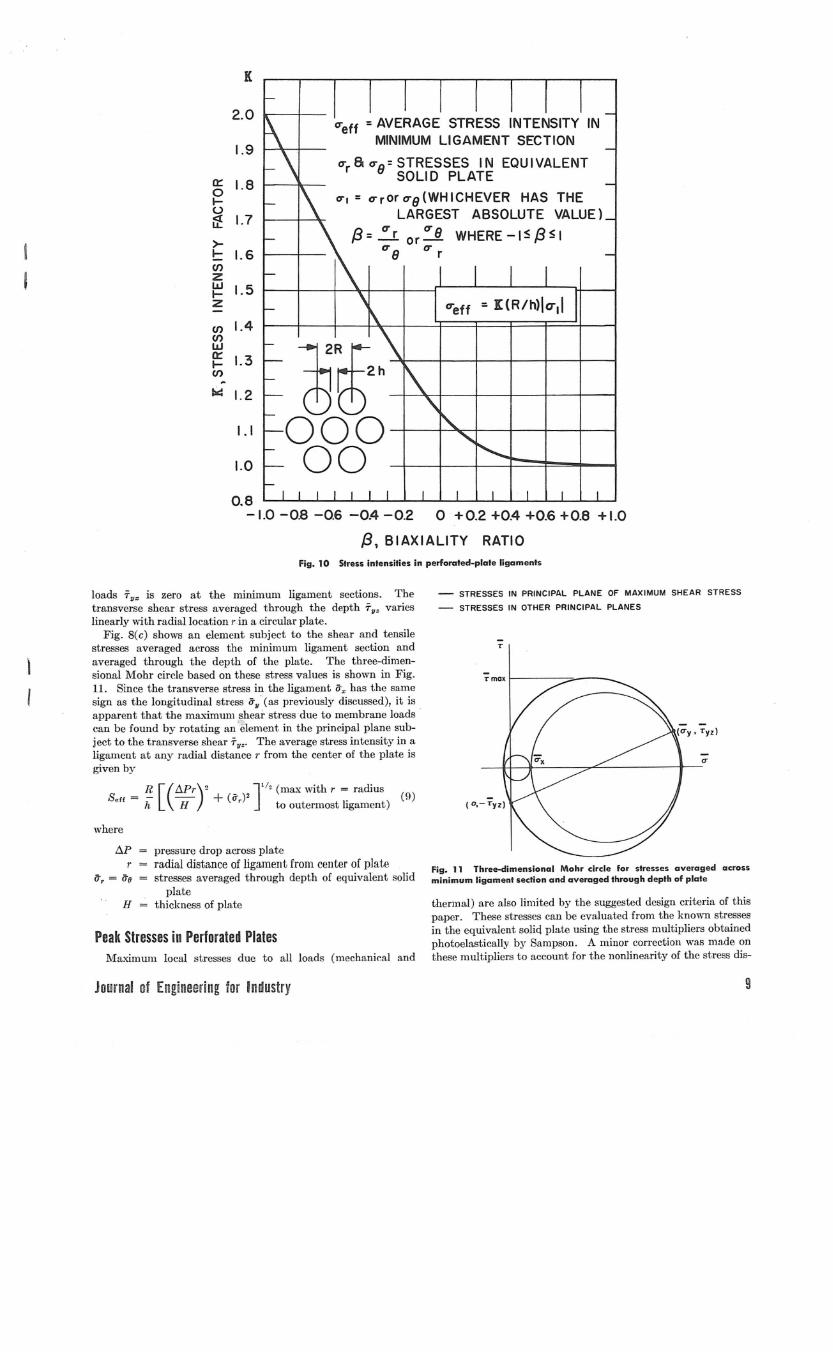
h/R, LIGAMENT EFFICIENCYFig. 12 Maximum local stresses in perforated plotes
tribution through the thickness of the coupons used by Sampson.The multipliers Yare functions of the biaxiality of the stressfield in the equivalent solid-plate fJ = (Jr/(Jo or (Jo/(Jr (whichevergives -1 ~ fJ ~). This ratio varies, of course, with radialloca-tion in the plate. The maximum stress for any particular thermalor pressure load is then given by the relation:
(10)
where
(J1 (Jr or (Jo (whichever has the largest absolute value)Y value given in Fig. 12P pressure acting on surface
All thermally induced maximum local stresses, as well as pres-sure stresses, must be considered in the cumulative fatigue limita-tions on the values of (Jm,,' The values given by equation (10)are the peak stresses throughout the perforated portion of theplate.
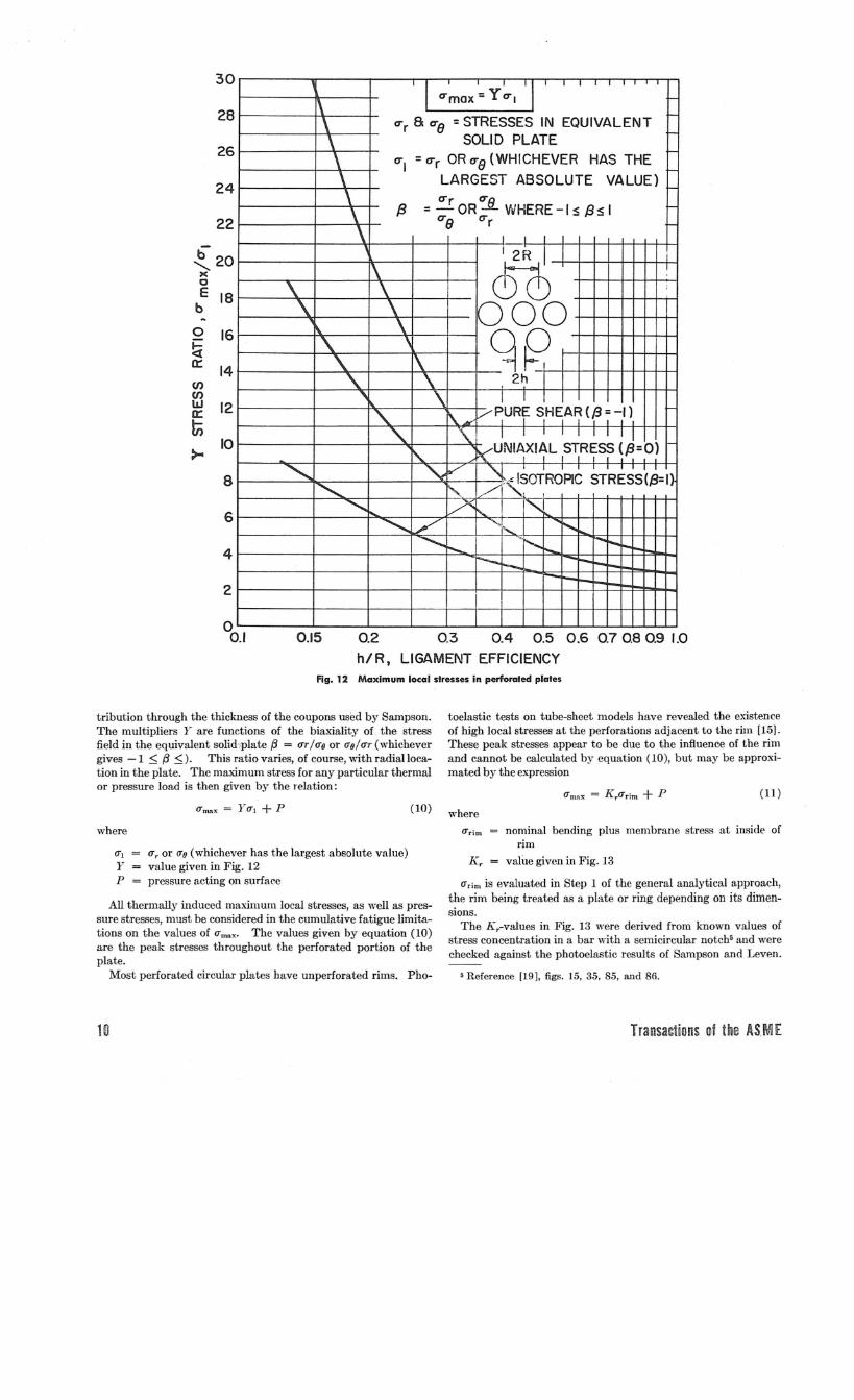
Most perforated circular plates have unperforated rims. Pho-
10
toelastic tests on tube-sheet models have revealed the existenceof high local stresses at the perforations adjacent to the rim (15].These peak stresses appear to be due to the influence of the rimand cannot be calculated by equation (10), but may be approxi-mated by the expression
(11)
where(Jrim nominal bending plus membrane stress at inside of
rim[(r value given in Fig. 13
(Jrim is evaluated in Step 1 of the general analytical approach,the rim being treated as a plate or ring depending on its dimen-sions.
The Kr-values in Fig. 13 were derived from known values ofstress concentration in a bar with a semicircular notch5 and werechecked against the photoelastic results of Sampson and Leven.
5 Reference [191. figs. 15.35.85. and 86.
Transactions of the UME
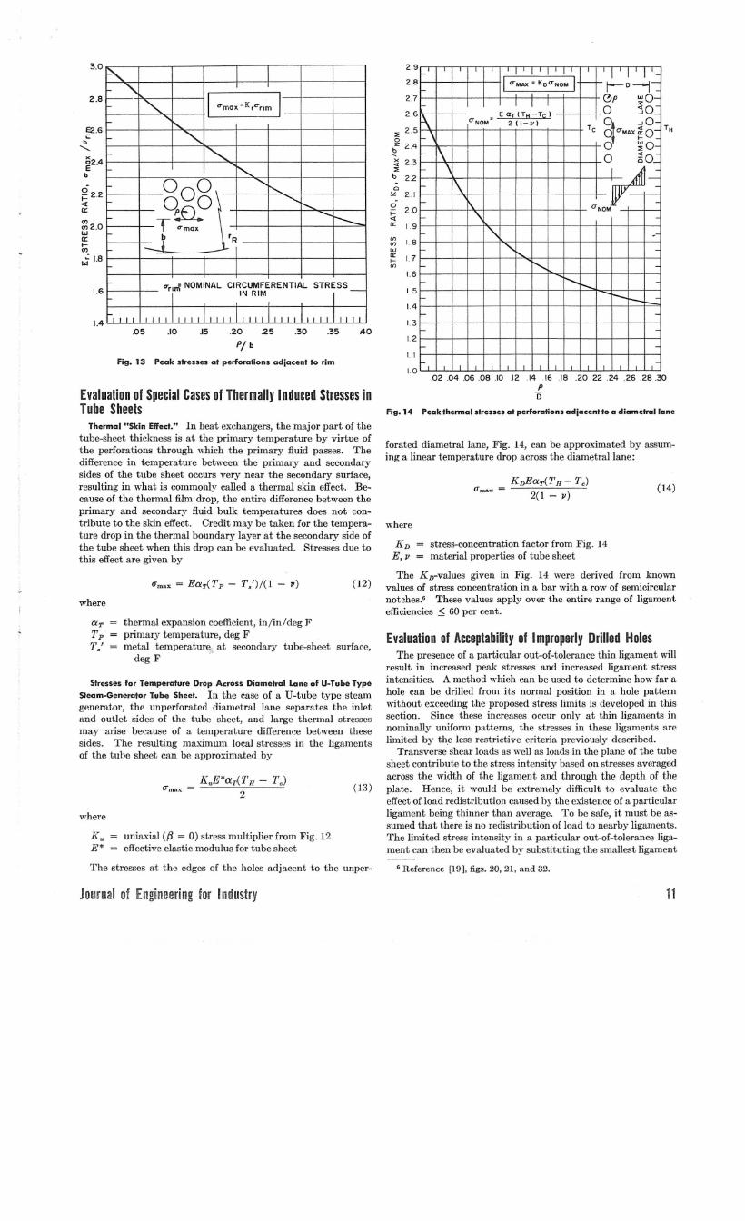
Fig. 13 Peak stresses at perforations adjacent to rim
O'"mox =K rC"'nm
, I I I I I I I II CTMAX = KOO"NOM 1- j-D-j-I I I (!)p ~o-
\ EaT(TH-Tc) 0 50_CTNOM
,2 (1- v) o~ -,0-
\Tc o O"MAX ~o-
\o ~o0 ~o_
\
~\
\."\
UNOM
"- -.......... -
...•...........•... -r--I--
-
, , , ,
2.3
2.4:; 2.5oz~x<l:;b 2.2
1.1
2.9
2.8
2726
14
1.3
1.2
1.5
~ 1.8w~ 1.7If)
1.0
1.6
a'" 2.1
g 2.0<l0:: 1.9
.40.35
STRESS
.30.20 .25
PI b
.15.10.05
2.8
3.0
1.6
1.4
g22<l:a:
~2.0wa:f-(J)
ti 1.8
§2.6b~
•.....•..
~2.4b
Evaluation of Special Cases of Thermally Induced Stresses inTube Sheets
.02 .04 .06.08 .10 .12 .14 .1618 .20.22 .24 .26 .28.30Po
Fig. 14 Peak thermal stresses at perforations adjacent to a diametrallane
where
K" uniaxial (/3 = 0) stress multiplier from Fig. 12E* effective elastic modulus for tube sheet
The stresses at the edges of the holes adjacent to the unper-
aT thermal expansion coefficient, in/in/deg FTp primary temperature, deg FT/ metal telnperature, at secondary tube-sheet surface,
deg F 0
(l4)KDEaT(TH- 7'.)
2(1 - II)([max
where
Evaluation of Acceptability of Improperly Drilled HolesThe presence of a particular out-of-tolerance thin ligament will
result in increased peak stresses and increased ligament stressintensities. A method which can be used to determine how far ahole can be drilled from its normal position in a hole patternwithout exceeding the proposed stress limits is developed in thissection. Since these increases occur only at thin ligaments innominally uniform patterns, the stresses in these ligaments arelimited by the less restrictive criteria previously described.
Transverse shear loads as well as loads in the plane of the tubesheet contribute to the stress intensity based on stresses averagedacross the width of the ligament and through the depth of theplate. Hence, it would be extremely difficult to evaluate theeffect of load redistribution caused by the existence of a particularligament being thinner than average. To be safe, it must be as-sumed that there is no redistribution of load to nearby ligaments.The limited stress intensity in a particular out-of-tolerance liga-ment can then be evaluat-ed by substituting the smallest ligament
G Reference [191. figs. 20, 21, and 32.
KD = stress-concentration factor from Fig. 14E, II = material properties of tube sheet
The KD-values given in Fig. 14 were derived from knownvalues of stress concentration in a bar with a row of semicircularnotches.6 These values apply over the entire range of ligamentefficiencies :::;60 per cent.
forated diametrallane, Fig. 14, can be approximated by assum-ing a linear temperature drop across the diametrallane:
(13)
(12)
K"E*aT(TH - TJ2
O"max
where
Thermal "Skin Effect." In heat exchangers, the major part of thetube-sheet thickness is at the primary temperature by virtue ofthe perforations through which the primary fluid passes. Thedifference in temperature hetween the primary and secondarysides of the tube sheet occurs very near the secondary surface,resulting in what is commonly called a thermal skin effect. Be-cause of the thermal film drop, the entire difference between theprimary and secondary fluid bulk temperatures does not con-tribute to the skin effect. Credit may be taken for the tempera-ture drop in the thermal boundary layer at the secondary side ofthe tube sheet when this drop can be evaluated. Stresses due tothis effect are given by
Stresses for Temperature Drop Across Diametral Lane of U-Tube Type
Steam-Generator Tube Sheet. In the case of a U-tube type steamgenerator, the unperforated diametral lane separates the inletand outlet sides of the tube sheet, and large thermal stressesmay arise because of a temperature difference between thesesides. The resulting maximum local stresses in the ligamentsof the tube sheet can be approximated by
Journal of Engineering for Industry 11
I '. I I I I I I
1/ Kmh'~"1Q
-l\ I
11"0\ \ ~,,\, -!
-_.I'\ " I
- !- 11"1 I\~ -I
\
\ \
'1\ -
1\ \~ -
1 \ .\1\-
f"\
II"-I~ \ ,~ -
"< i'-.. ."'- ~ -
"""'"~ ~ ~ -
I I I I I I I I I I I
3.4
3.2
3.0
2.8
I-II- 2.6zzIJJ,uJ--':;;: 2.4""1-<<r<.:lICl
~-J 2.2O-JIU<l: 2.0u:<::>a:fi:loa:z 1.8ZZVlVl 1.6VlVlwWa: a: 1.41-1-VlVl~~ 1.2«<l:ww0..0.. 1.0;;e
0.8
0.6
0.4
0.2
oo
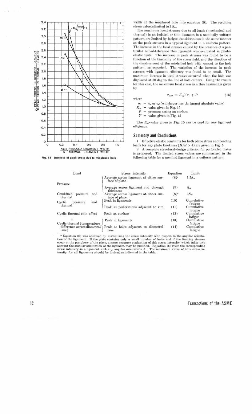
fig. 15
Q2 Q4 Q6 Q8 IDhmln REDUCED LIGAMENT WIDTH-h-" NORMAL LIGAMENT WIDTH
Increase of peak slress due 10 misplaced hole
width at the misplaced hole into elJuation (9). The resultingstress value is limited to 3 S""
The ma),i/lllJlll local stresses tlue (,0 all loatls (mcchanical alltlthermal) ill tm iso!:J.tedor thin ligament in a nominally uniformpattcrn are limitlxl by fatigue considerations in the same manneras the peak stresses ill a typical ligament in a uniform pattern.The increase in the Joeal stresses caused by the presenee of a par-ticular out-of-tolerance thin ligamen(, was evaluated in photo-elastic tests. The inerease in peak stresses was found to be afunction of the biaxiality of the stress field, and the direction ofthe displacement of the misdrilled hole with respect to the holepattern, as expected. The variation of the increasc in peakstresses \dth Jig:uneut efTiciclll'Ywas foulld (,0 be small. Themaximum increase in local stresses occurred when the hole wa~displaced at 30 deg to the line of hole centers. Using the resultsfor this ease, the maximum loeal st.ress in a.thin ligament is givenby
(15)where
<TI <Tr or <To (whiehever has t.he largest absolute value)K", value given in Fig. 15
P pressure acting on surraeeY value given in Fig. 12
The K",-v:tlue givcn in Fig. 15 can be used for any ligamentefficieney.
Summary and Conclusions1 Effeetive elastic constants for both plane stress and bending
loads for any plate thickness (H/R > 4) are given in Fig. 5.2 A complete structural-design criterion for perforated plates
is proposed. The limited stress values are summarized in thefollowing table for a nominal ligament in a uniform pattern.
';' ( Peak ill ligamentsCyclic thermal (temperature 1
difference across diametral Peak at holes adj:tcentlane) lane
Load
Pressure
Coml.:ined pressure andthermal
Cyclic pressure andthermal
Cyclic thermal skin effect
Stress intensity( Average across ligament at either sur-
I face of plate
Average across ligament and throughthickness
Average across ligament at either sur-face of plate
{Peak in ligaments
Peak at perforations adjacent to rim
Peak at surface
to diametral
Equation Limit(8)" 1.58",
(9) 8m
(8)" 38",
(10) Cumulativefatigue
(11) Cumulativefatigue
(12) Cumulativefatigue
(13) Cumulativefatigue
(14) Cumulativefatigue
12
o Equation (8) was obtaincd by maximizing thc stress intensity with respect to the angular orienta-tion of the ligament. If the plate contains only a small number of holes and if the limiting stressesoccur at the periphery of the plate, a more accurate evaluation of this stress intensity. which takes intoaccount the angular orientation of the ligament may be justified. Equation (6) gives the correspondingstress intensity in a ligament with any angular orientation f. The maximnm value of this stres>;irl-tensity for all ligaments should be limited as indicated in the table.
TransacHons of the AS M E
Journal oi Engineering for Industry
EquationEquation (9) with
hmiH substitutedfor h
(15)
3 A method of evaluating the acceptability of misdrilledholes is given. The relevant stresses and their proposed limitsare given in the following table.
Limit3S",
Cumulativefatigue
3 1. Malkin, "Notes on a Theoretical Basis for Design of TubeShects of Triangular Layout," TRANS. ASME, vol. 74, 1952, pp.387-396.
13
l"'inted in U. S. A.
4 K. A. Gardner, "Heat Exchanger Tube Sheet Design,",Journal of Applied 111echanics, vol. 15, TRANS.ASME, vol. 70, 1948,pp. 377-385.
5 K. A. Gardncr, "I-Ieat E.'xchanger Tube Sheet Design-2, FixedTube Sheets," Jottrual of Applied Jllechanics, vol. HI, TUANS.ASME,vol. 74, 1952, pp. 159-lG6.
6 K. A. Gardner, "Heat Exchanger Tuhe Sheet Design-3,U-Tube and Bayonet Tube Sheets," Journal of AP1Jlied 111eehanics,vol. 27, TRANS.ASME, Series E, vol. 82, 1960, pp. 25-33.
7 J. P. Duncan, "The Structural Efficiency of Tube Plates forHeat Exchangers," Proc:eerlings, I. 111eeh. E., vol. 169, 1955, pp.789-810.
8 K. A. G. i\liJler, "The Design of Tube Plates in Heat Ex-changers," Proceedings, I. ilIech. E., vol. 1 13, 1952, pp. 215-231.
9 G. D. Gallet!y and D. It. Snow, "Some Results on Con-tinuously Drilled Fixed Tube Plates," IJresented at the ASMEPetroleulll Conference, Nmv Orleans, La., September, 1960, PaperNo. 60-Pet-16.
10 V. L. Salerllo and J.B. i\fal1OlIcy, "A Heview, Comparison andi\Codification of Presen t Deflection Theory for Flat PerforatedPlates," Welding Research Council Bulletin No. 52, July, 1959.
11 "Standards of Tubular Exchanger Manufacturers Associa-tion," fourth edition, Tubular Exc:hanger Manufacturers Association,New York, N. Y., 1959.
12 S. Timoshenko and S. Woinowsky-Krieger, "Theory ofPlates aud Shells," second edition, McGraw-Hill Book Company.Inc., New York, N. Y., 1959, p. 5(;.
13 R. C. Sampson, "Photoe1asti<.: Frozen Stress Study of theEffective Elastic Constants of Perforated Materials, A ProgressReport," WAPD-DLE-3f9, May, 1959; available from Office ofTeehni<.:al Service, Department of Commerce, \Vashington 25, D. C.
14 i\if. i\L Levell, "Preliminary Report on Deflection of TubeShel,ts," vVAPD-DLE-320, i\Jay, 1959; available from Offiee ofTechnical Serviees, Departmcnt of eOlTlIlIer<.:e,vVashington 25, D. C.
15 i\f. lVI, Leven, "Photoelastic Determinat.iolT of Stresses inTube Sheets and COlllparison "Tith Calculated Value'S," Bettis Tech-nical Review, vVAPD-BT-1S, April, 1960; available from Office ofTechnical Services, Department of Commerce, \Vashington 25, D. C.
I6 W. J. O'Donnell, "The Effect of the Tubes on Stresses andDeflections in U-Tube Steam Generator Tube Steets," Bettis Tech-nical Review, \VAPD-BT-21, Novembe'r, 1960; available fromOffice of Teehnieal Services, Department of Commerce, vVashington25, D. C.
17 B. F. Langer, "Design Values fol' Thermal Stress in DuctileiVlaterials,', ASi\IE Paper No. 58-Met-l, The Weldina Joumal, Re-search Supplement, September, 1958, pp. 411s-417s.
18 R. C. Sampson, "Photoelastic Analysis of Stresses in Per-forated Material Subject to Teusion 01' Beuding," Bettis TechnicalReview, WAPD-BT-18. April, 1960; available from Office of Tech-nical Services, Department of Commerce. \Vashington 25, D. C.
19 R. E. Peterson, "Stress-Concentration Design Factors," JohnWiley & Sons, New York, N. Y, 1953.
Stress intensityAvera-ged across ligamen t
and through depth
Peak in ligaments
LoadCombined pressure
and thermal
Cyclic pressure andthermal
References1 G. Horvay, "The Plane-Stress Problem of Perforated Plates,"
JO'll1"1talof Applied 111echanies, vol. 19, TRANS.ASME, vol. 74, 1952,pp. 355-360.
2 G. Horvay, "Bending of Honeycombs and Perforated Plates,"Journal of A1Jplied 111eehanics,"'ol. 19, TRANS.ASME, vol. 74, 1952,pp. 122-123.
7 See reference [14], figs. 7-11, and reference [15], figs. 18, 19,20,24,and 25
4 The effective elastie COlJstalJbi and peak stress multipliersrecommended herein are based on those obtained experimentallyby Sampson. Stresses and ddlec:tiolls caleulated using thesevalues showed better agreement with the test results obtainedby Leven (on uniformly loaded, simply supported, circulnr per-forated pl:Ltes) thalJ any of the other appro:Lehl~s mentioned
herein!For most conventional steam generators, the design basis
recommended herein allows a slightly thinner tIl be sheet than doesTEMA [11]. For example, in a typiclll high-pressure designwhere TE:MA requires It minimum tube-sheet thid:ness of 10 in.,the design methods descrihed herein require a minimum thicknessof 91/, in. if S", is taken as 5/s of the yield strength of the materialand full credit is taken for the tubes. On the other hand, wheresevere thermal loads are antieipated, it may be necessary to makedesign modifications in order to meet the criteria recommendedherein, whereas TEMA does not account for thermal loads.
AcknowledgmentsThe design methods proposed on this paper are the culmination
of a program sponsored by the Bureau of Ships and co-ordinatedby the vVestinghouse Bettis Atomic 1'o"'er Laboratory. Thestress limits proposed, however, represent only the opinions of theauthors. The experimental work used as a basis for the pro-posed design methods was performed by Messrs. IVr. .M. Levenand R. C. Sampson at the \Vestinghouse Research Laboratoriesand by Mr. A. Lohmeier at the vVestinghouse Steam Division.To avoid duplication of effort, the program was co-ordinated bythe authors with a somewhat broader program on stresses inligaments being sponsored by the Pressure Vessel ResearchCommittee of the vVelding Research Couneil.