Design of Optimized Engine for Direct Sequence Spread ...ece734/project/s04/raja.pdf · for Direct...
53
Design of Optimized Engine for Direct Sequence Spread Spectrum Transceiver ECE 734 Project Report Spring 2004 Prepared By: Harish Rajagopal Varun Nawani
Transcript of Design of Optimized Engine for Direct Sequence Spread ...ece734/project/s04/raja.pdf · for Direct...
Design of Optimized Engine for Direct Sequence Spread
Spectrum Transceiver
ECE 734 Project Report
Spring 2004
Prepared By: Harish Rajagopal
Varun Nawani

Contents
1 Introduction
2 Theoretical Background for Direct Sequence Spread Spectrum
3 Implementation of Direct Sequence Spread Spectrum Engine 3.1 Acquisition
3.2 Tracking
3.3 Overall Design Implementation
3.4 System Optimization
3.4.1 Digital Matched Filter Optimization
3.4.2 Loop Filter Optimization
4 Simulation And Results 4.1 Verification of Digital Matched Filter Implementation
4.2 Performance of Direct Sequence Spread Spectrum Engine
4.3 Acquisition Performance
4.4 Tracking Performance
4.5 Results
5 Conclusion
6 References
Appendix A: Verilog Code for Optimized DSSS Engine
Appendix B: Verilog Code for Un-Optimized DSSS Engine

1. Introduction
The interference in the wireless communication channel leads to
spreading of the data to be transmitted over the entire frequency range thereby
making it resistant to noise. One of the popular techniques for spreading of the
data is Direct Sequence Spread spectrum (DSSS). It is used in popular
applications such as IEEE 802.11b and CDMA. The data that is to be transmitted
wirelessly is multiplied with a high frequency pseudo-random noise (PN)
sequence at the transmitter. This causes the spreading of the power spectral
density. The basic building blocks of the transceiver unit in DSSS consist of a
pseudo random sequence generator, Digital Matched filter, Delay locked loop
which consists of a detector, loop filter and numerically controlled oscillator.
At the receiver side the data is again multiplied with the same PN
sequence that is locally generated to recover back the original data symbols. The
most sensitive part of a Direct Sequence Spread Spectrum system is the
synchronization of the transmitter’s pseudo random sequence to that of the
receiver where an offset of even one chip cycle can result in noise rather than a
de-spread symbol sequence. Our project mainly focuses at the design of a fast
Direct Sequence Spread Spectrum engine such that there is a faster correlation
between the pseudo random sequence at the transmitter and the receiver.
2. Theoretical Background for Direct Sequence Spread Spectrum
The basic building block of the DSSS transmitter is shown below. The
symbol to be transmitted is multiplied with the PN sequence to generate the
spread symbol. The symbols are converted to analog form and are transmitted
after the modulation.

Figure 1: Basic DSSS Transmitter
The multiplication of the symbol with the PN sequence causes the
increase in the bandwidth by a factor known as the processing gain (PG). PG is
calculated by the ratio of symbol period, Ts, to the chip period of the PN
sequence, Tc: where Ts >> Tc.
=
C
S
TT
PG 10log.10
This results in the lowering of the peak power spectral density by the
processing gain.
Figure 2: Power Spectral density of Transmitted signal
The transmitted spread spectrum signal is thus a wideband signal that can
hardly be differentiated from channel noise, if the processing gain is high enough.
The amount of degradation faced by the signal in the transmission channel is
dependent on the degree and characteristics of interference sources present in

the channel. One of the advantages of spread spectrum its resistance to
narrowband noise. As we can see from the figure below, the spectrum of the
signal is so much wider than that of the narrowband interferer that most of the
signal power can still be received.
Figure 3: Narrow band Interference in Transmitted signal
The basic building block of the receiver is shown below. The received
signal is multiplied with a local replica of the transmitter’s PN sequence to
despread the signal the original data symbols. The local oscillator at the receiver
is assumed to be in synchronization with the oscillator at the transmitter.
Figure 4: Basic DSSS Receiver
The spread spectrum of the symbols recovered by the receiver along with
the noise added during transmission is shown below.

Figure 5: Power Spectral Density in the received signal
As we can see the interference is spread by the receiver as the data is
being despread. The timing diagram of the entire process is shown below.
Figure 6: Timing sequence of Spreading and Despreading
Direct sequence spreading can be done with short or long PN sequences.
A short PN sequence, Nc chips long, has a period equal to that of the symbol Ts.
Therefore, Nc.Tc=Ts where Tc is the chip period. A long code on the other hand
has a length several symbols long, Nc.Tc >> Ts. Therefore each symbol is
spread by a seemingly different chip pattern. If the PN sequences are perfectly
orthogonal then there is no interference between the users after dispreading and
the privacy of the communication of each user is protected. There are many

types of spreading sequences and methods of producing them. The type of
sequence we use depends on the communication channel using it.
The most sensitive aspect of a DS system is the synchronization of the
transmitter’s PN sequence to that of the receiver where an offset of even one PN
chip can result in noise rather than a despread symbol sequence.
Synchronization is composed of two elements namely acquisition and tracking.
These can be viewed as the alignment of the PN sequences, and the
maintenance of this aligned state. Synchronization systems use correlators to
determine the correlation of the received signal to the local replica of the
transmitted PN sequence. When a high correlation value is detected, acquisition
has been achieved. How fast the data is received depends on the how fast the
correlation between the PN sequences is achieved.
3. Implementation of Direct Sequence Spread Spectrum Engine
The DS spreading code synchronization system consist of two processes:
acquisition and tracking. The acquisition process provides the initial
synchronization between the local and incoming spread sequences with an
accuracy of + 0.5 of the chip clock. The tracking processes then achieves fine
synchronization and maintains it.
3.1 Acquisition
Correlator architectures are often categorized as either serial (active) or
parallel (passive). Serial correlators multiply the received signal with the local PN
sequence and accumulate the result on a chip-by-chip basis for the duration of a
symbol. If the required threshold is not met by the correlation value, a new
correlation process is initiated. Thus for a PN sequence of length Nc chips, and a
symbol duration of Ts seconds, it could take up to Nc.Ts seconds to achieve
acquisition. Parallel correlator architectures are based on matched filters. These
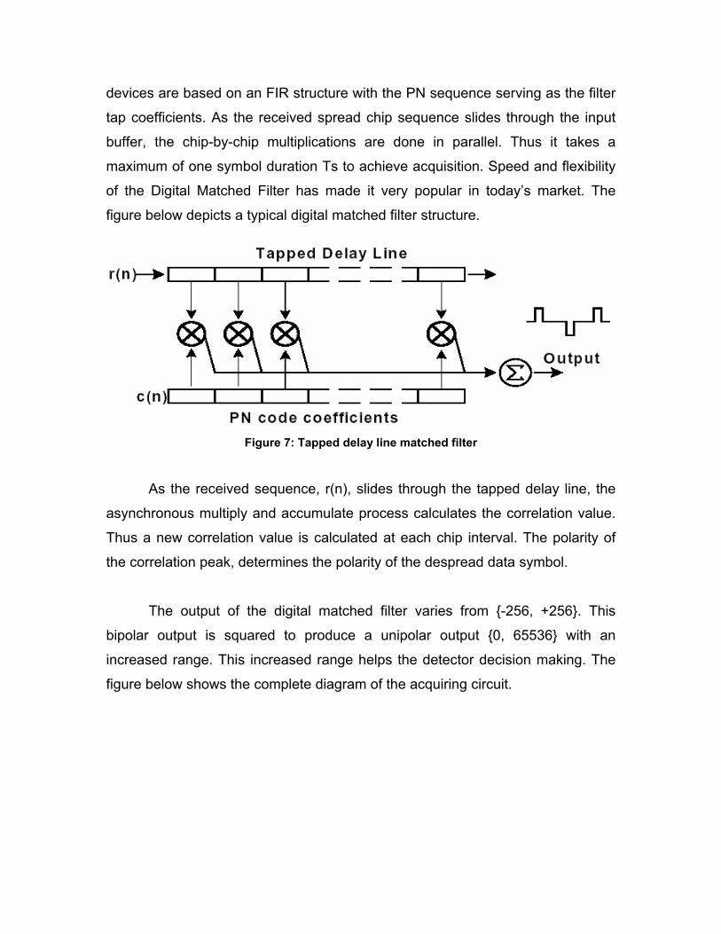
devices are based on an FIR structure with the PN sequence serving as the filter
tap coefficients. As the received spread chip sequence slides through the input
buffer, the chip-by-chip multiplications are done in parallel. Thus it takes a
maximum of one symbol duration Ts to achieve acquisition. Speed and flexibility
of the Digital Matched Filter has made it very popular in today’s market. The
figure below depicts a typical digital matched filter structure.
Figure 7: Tapped delay line matched filter
As the received sequence, r(n), slides through the tapped delay line, the
asynchronous multiply and accumulate process calculates the correlation value.
Thus a new correlation value is calculated at each chip interval. The polarity of
the correlation peak, determines the polarity of the despread data symbol.
The output of the digital matched filter varies from {-256, +256}. This
bipolar output is squared to produce a unipolar output {0, 65536} with an
increased range. This increased range helps the detector decision making. The
figure below shows the complete diagram of the acquiring circuit.

Figure 8: Acquisition Block Diagram
Before acquiring the PN sequence, the threshold constantly compares the
received signal to its threshold. Once this threshold has been met (acquisition
has been achieved) the detector sends a signal to the tracking circuit to start the
tracking process. From this point on, the threshold comparison is done at symbol
intervals. This is where the numerically controlled oscillator (NCO) comes in. It
pulses the detector at every symbol period so that the detector can do its
threshold comparison and output the despread data if still in acquisition. NCO is
modeled as a counter that counts at the chip rate up to its maximum value of
255. When this expires, it activates the detector.
3.2 Tracking
A time varying transmission channel can cause delays in the received DS
spread spectrum signal. This in turn causes the previously acquired PN
sequence to fall out of acquisition if no sampling time correction mechanism is
used. This mechanism is the tracking circuitry. The delay-locked loop (DLL),
sometimes called the “early-late gate”, is a common device used for tracking in
DS systems. The figure below shows a DLL that consists of two branches, each
very much similar to the acquisition circuitry.

Figure 9: Tracking Block Diagram
The upper branch called the “early branch” employs a replica of the DMF
used in the acquisition circuit, except that its PN sequence is advanced by a
fraction of one chip period. This fraction depends on the over-sampling rate of
the PN. We have used an over-sampling of 16. The DMF used by the bottom
branch, called the “late branch” contains the same PN sequence, however
retarded by a fraction of a chip period. If the incoming signal is on time, the
acquisition branch will sample at the peak correlation value and the two DLL
branches’ outputs will be equal, causing no error. If the incoming signal is
delayed, one of the two branches of the DLL will output a higher value than the
other. The difference of the two outputs, known as the timing error, is averaged
out by the loop filter to produce the dc value. The sign and magnitude of this dc
value then determines how much the phase of the NCO must be corrected to
eliminate the timing error.
Loop Filter
The timing error sometimes exhibits erroneous jitter that can mislead the
NCO’s timing circuitry. The FIR filter shown below, is used to average out the
timing error, e(n), so that a more accurate delay measurements, z(n), reaches
the NCO. The equation for the filter is as given below.
Z(n) = e(n)h(0) + e(n-1)h(1) + e(n-2)h(2) +e(n-3)h(4)

The structure of the Loop filter is given in the figure below.
Figure 10: Loop Filter Structure
The four-tap filter was expected to exhibit the frequency response
according to Matlab simulations. This shows that frequencies less than 10 KHz or
so, pass through unharmed. However high frequency components, especially
those above 30 KHz or more, suffer more than 10 dB of attenuation. The
Magnitude and phase response for the FIR filter is as given below
Figure 11: Magnitude plot of frequency Response for the Loop FIlter

Figure12: Phase plot of the frequency response for the loop filter
3.3 Overall Design Implementation
Figure 13: Overall Design Implementation Block Diagram
The overall system diagram is shown in the figure above. As we can see
the incoming bit-stream coming from an ADC is input to the system. The
acquisition branch of the system is used for the initial acquisition of the symbol.
Once the acquisition is complete the detector outputs the de-spread data
sequence. This branch can also be reused in the transmission mode to transmit

the data. This system design is based on a dual phase system such as a Binary
Phase Shift keying (BPSK) system.
3.4 System Optimization
As we said earlier, the most important part in the PN synchronization is
the digital matched filter, so optimizing the structure of the digital matched filter
was the main concern in our project.
3.4.1 Digital Matched filter optimization
The digital matched filter is similar to a tapped delay line which is
multiplied by the PN coefficient sequence. The diagram of the Digital Matched
Filter shown above can be simplified to the form shown below. This makes it
easier for us to analyze the circuit as its form is very similar to the one studied
and optimized in the class. Here x(n) is a bipolar input.
Figure 14: Conventional Digital Matched filter
The problem with conventional digital matched filter is that the integration
period of the matched filter is limited by the device length. Also despite of the fast
acquisition that the matched filter can provide, its application for long PN
spreading sequences results in significant false alarm probability or complexity
increase. Hence we now concentrated increasing the integration period of the
matched filter and decreasing the false alarm probability with minimum increase
in hardware complexity.
As we can see from the above diagram that the input sequence multiplies
with the locally generated PN sequence. The first change made by us was that
we used XOR gates instead of multiplication. For achieving this we first shifted
the input from bipolar to binary form. The PN sequence was also converted from
bipolar to binary form. This simplified the multiplication operation required to a
simple XOR operation. The critical path of the Digital matched filter now became
Tcrit = TA +TA +TA+... TA+ TXOR
The taps for the digital matched filter are obtained from sampling of the PN
sequence. We are considering a test PN sequence of 16 bits. With an over-
sampling of 16 bits, the number of taps becomes 256. For a 256 tap digital
matched filter that we are considering the equation becomes
Tcrit = 256*TA +TXOR ---------------- (1)
The next optimization that we applied was to reduce the critical path of the
Digital matched filter. This was achieved in the same manner as that for a FIR
filter by applying the Transposition Theorem to the signal flow graph of the
digital matched filter. After applying the transposition theorem to the above
graph we obtained the data- broadcast architecture as shown in the figure below.

Figure 15: Optimized Digital Matched Filter design
The output of the Digital Matched filter was converted to a bipolar output
so that we could have a higher range for correlation. This was done by adjusting
the bit range from {0 to 256} to {-256 to +256}. This gives us a 10 bit 2’s
complement number. The critical path of the optimized digital matched filter is
now given by the following equation
Tcrit = TXOR + TA ---------------- (2)
This is much smaller than the critical path for the un-optimized digital
matched filter. This optimization holds true independent of the number of taps of
the matched filter. i.e., even if the number of taps had been 512 the optimized
critical path would be given by equation 2. Considering an XOR with delay 2nS
and adder with delay of 12 nsec the reduction in critical path is approximately
99.5%. The critical path is reduced from 3072 nsec to 14 nsec. This improvement
in critical path allows us to sample the PN sequence as well as the incoming data
at a higher rate. This increase in sampling period only needs to be limited by the
requirements of the Analog to Digital Converter or the critical path.
x(n)
Output
XOR XOR XOR XOR
c(N-1) c(N-2) c(N-3) c(0)

The higher sampling rate possible will increase the number of taps in the
digital matched filter that can be used in the digital matched filter. This number
can increase exponentially and causes increased hardware utilization. To offset
this increase in hardware utilization that makes increasing the sampling rate
seem unattractive we needed to develop a method that actually reduces the
hardware utilization and optimizes the matched filter in both speed and area. The
conventional Digital Matched filter shown earlier requires increased area and
increased critical path with the increased number of taps unlike our
implementation. Thus we have successfully fulfilled the requirements of our
design, namely an unlimited period for integration with the least increase in
hardware.
3.4.2 Loop Filter Optimization
The loop filter is basically a simple FIR filter used to smooth the error
signal obtained by the subtracter node. Since the main requirement for the FIR
filter is smoothing we are using an averaging filter that averages over for data
over four clock periods. We have used powers of 2 as the coefficients for the FIR
filter since it is an averaging operation over 4 clock cycles. The clock period used
is four time that of the chip clock to maintain the timing requirements. The basic
loop filter structure shown in figure 10 has a critical path of
Tcrit = 3*TA+TM
Since the coefficients are powers of two we can reduce the multiplication
operation to a shifting operation which requires less time. We can easily do this
by discarding the last two bits of the input data. This structure is further optimized
using the Transposition Theorem as shown below.

Figure 16: Optimized loop filter
The critical path of the structure is now as shown below.
Tcrit = Tshift+ TA
Since the shift operation is virtually zero, as we are just discarding the last
two bits, the critical path becomes
Tcrit = TA
Hence this filter also does not limit the sampling speed at the input of the
Digital matched filter.
4. Simulations and Results
4.1 Verification of Digital Matched filter Impulse Response
After implementing the Digital Matched filter in hardware we verified the
impulse response of the hardware using MATLAB. The digital matched filter was
implemented using MATLAB and identical input sequences were passed through
both the structures. The hardware implementation was simulated using
ModelSim Verilog simulator using a test bench written for it. The responses
obtained are both plotted below.

Figure 17: Filter outputs for Digital Matched filter from Matlab and Verilog
4.2 Performance of Direct Sequence Spread Spectrum Engine
The time taken for acquisition and that taken for tracking was compared
between that of the optimized and un-optimized structure. A total of 16 symbols
were used with a PN sequence of length 16 and over sampling of 16 in the case
of the un-optimized structure and 256 in the case of optimized structure. The
following are the results obtained from the simulation. Bit errors have also been
introduced to test the stability of the Direct Sequence Spread Spectrum Engine.
The figures below show the inputs and outputs obtained from the Direct
Sequence Spread Spectrum Engine Implementation. The important pins required
for interpreting the data from the figures are given below. The input X gives the
sequential spread spectrum input to the system. The PN gives the 256 bit PN
sequence used. The pins S0 and S1 give the output from the system. The pin S0

becomes high when the received symbol is found to be zero and S1 becomes
high when the received symbol is found to be one. Both of them cannot be one at
the same time, but they can be zero at the same time, indicating that the receiver
is not able to detect what the symbol is. The pin ACQ becomes high when the
signal is acquired and remains high until the signal is found to be out of
synchronization. The value counter gives us the state of the NCO which is
incremented as long as the engine is in acquisition.
(a)
(b)
Figure 18: Waves from outputs of the (a) un-optimized and (b) optimized DSSS engines
The above figure shows the performance comparison of the un-optimized
and optimized systems designed for Direct Sequence Spread Spectrum Engine.
We can observe a performance improvement immediately from the figure. The
acquisition performance is far better with the Optimized structure acquiring
almost instant acquisition as compared to the un-optimized structure. The un-
optimized structure also displays falling out of acquisition mode at different
places when the errors are introduced. The optimized structure displays instant
resynchronization even after bit errors are introduced. The un-optimized structure

does not show the points where resynchronization occurs because of a feature
we had added by which the output remains in the state where it was before
falling out of resynchronization for one symbol period. But if there are double
symbol errors then the engine falls out of synchronization. In contrast the un-
optimized engine which does not have that feature shows better performance.
The reason that we did not introduce this feature to the optimized engine was
that it added to the critical path thus reducing the sampling speed which was
undesirable.
4.3 Acquisition performance
The figures below show the acquisition performance of the un-optimized
and the optimized structure. Essentially the optimized structure shows instant
acquisition as compared to the un-optimized structure which requires multiple
symbol delays before acquisition.
(a)
(b)
Figure 19: Waves from outputs for (a) un-optimized and optimized DSSS Engine for comparing acquisition performance

4.4 Tracking performance
The tracking performance of the un-optimized and optimized direct
sequence spread spectrum engine is compared below. The tracking is clearly
seen to be lost in the case of the un-optimized engine. This can be verified by the
fact that the counter which is supposed to incrementing while tracking is at zero.
In comparison the optimized engine has fallen out of acquisition and tracking but
regains it almost instantly.
(a)
(b)
Figure 20: Waves from (a) un-optimized and (b) optimized DSSS structure used for comparing tracking

4.5 Results
The simulation results that we obtained are representative of the increase
in speed that can be potentially obtained by using the optimized Direct Sequence
Spread Spectrum Engine. For comparison we have used only 256 times over
sampled sequence. But this result can be extended up till the sampling limit is
reached, which is dependent on the critical path. Since the critical path remains
constant irrespective of the number of taps used the limit for the sampling
frequency is limited by either the hardware capacity or 1/ Tcrit ie., 1/(TXOR+TA).
5. Conclusion
In conclusion we have implemented an optimized direct sequence spread
spectrum engine using signal flow algorithm to speed up the bottlenecks. This
optimized version has been compared with an un-optimized version and the
differences in performance and advantages had been noted. The performance
improvement has been in the comparison cases upto 96% with comparable
hardware utilization.

6. References
1. Rupert Baines and Doug Pulley, “A Total Cost Approach to Evaluating
different Reconfigurable Architectures for Baseband Processing in Wireless
Receivers,” IEEE Communications Magazine,
Volume: 41 Issue: 1: January 2003, Page(s): 105 - 113.
2. Chi-Kin Cha and Wong-Hing Lam, “ Efficient use of pseudo-noise sequences
in synchronous direct-sequence spread-spectrum multiple-access
communication systems,” In proceedings of the 44th IEEE Conference on
Vehicular Technology Conference, Volume: 1, 8-10 June 1994, Page(s):
540 –544.
3. Ming-Luen Lieu; Tzi-Dar Chiueh, “ A low-power digital matched filter for
direct-sequence spread-spectrum signal acquisition”, IEEE Journal of Solid-
State Circuits, Volume: 36 , Issue: 6 , June 2001 Pages:933 – 943.
4. Xiao-heng Tan; Shi-zhong Yang, “The design and FPGA realization of the
long PN code acquisition circuit based on digital matched-filter”, In
Proceedings of 2003 ASIC 5th International Conference, Volume: 2 , 21-24
Oct. 2003, Pages:744 – 747.
5. K.S. Shanmugan, “Estimating the power spectral density of ultra wideband
signals,” In Proceedings of the 2002 IEEE Conference on Personal Wireless
Communications, 15-17 December 2002, Page(s): 124 –128.
6. H.C. Miranda, P.C. Pinto, and S.B. Silva, “A self-reconfigurable receiver
architecture for software radio systems, Radio and Wireless Conference,” In
Proceedings of the 2003 IEEE Radio and Wireless Conference, 10-13 August
2003, Page(s): 241 – 244.

7. Yamamoto, J.S.; Kohno, R.; “Dynamic digital matched filter acquisition of DS
receiver” In the Proceedings of Spread Spectrum Techniques and
applications International symposium. 22-25 September 1996, Page(s): 131-
136.

Appendix A: Verilog Code for Optimized DSSS Engine `timescale 1ns/1ns `define clk 10 //chip clock `define fclk 5 //filter clock --> frequency = 2 x chip clock ////////////////////////////////////////////////////////// module newmacc(xn,HREG,CLK,RES,Y,result); parameter length = 256; input xn,CLK; input [length-1:0] HREG; input RES; output [9:0] Y; output [8:0] result; reg temp1; reg [1:0] temp2, temp3; reg [2:0] temp4, temp5, temp6, temp7; reg [3:0] temp8, temp9, temp10, temp11, temp12, temp13, temp14, temp15; reg [4:0] temp16, temp17, temp18, temp19, temp20, temp21, temp22, temp23, temp24, temp25, temp26, temp27, temp28, temp29, temp30, temp31; reg [5:0] temp32, temp33, temp34, temp35, temp36, temp37, temp38, temp39, temp40, temp41, temp42, temp43, temp44, temp45, temp46, temp47, temp48, temp49, temp50, temp51, temp52, temp53, temp54, temp55, temp56, temp57, temp58, temp59, temp60, temp61, temp62, temp63; reg [6:0] temp64, temp65, temp66, temp67, temp68, temp69, temp70, temp71, temp72, temp73, temp74, temp75, temp76, temp77, temp78, temp79, temp80, temp81, temp82, temp83, temp84, temp85, temp86, temp87, temp88, temp89, temp90, temp91, temp92, temp93, temp94, temp95, temp96, temp97, temp98, temp99, temp100, temp101, temp102, temp103, temp104, temp105, temp106, temp107, temp108, temp109, temp110, temp111, temp112, temp113, temp114, temp115, temp116, temp117, temp118, temp119, temp120, temp121, temp122, temp123, temp124, temp125, temp126, temp127; reg [7:0] temp128, temp129, temp130, temp131, temp132, temp133, temp134, temp135, temp136, temp137, temp138, temp139, temp140, temp141, temp142, temp143, temp144, temp145, temp146, temp147, temp148, temp149, temp150, temp151, temp152, temp153, temp154, temp155, temp156, temp157, temp158, temp159, temp160, temp161, temp162, temp163, temp164, temp165, temp166, temp167, temp168, temp169, temp170, temp171, temp172, temp173, temp174, temp175, temp176, temp177, temp178, temp179, temp180, temp181, temp182, temp183, temp184, temp185, temp186, temp187, temp188, temp189, temp190, temp191, temp192, temp193, temp194, temp195, temp196, temp197, temp198, temp199, temp200, temp201, temp202, temp203, temp204, temp205, temp206, temp207, temp208, temp209, temp210, temp211, temp212, temp213, temp214, temp215, temp216, temp217, temp218, temp219, temp220, temp221, temp222, temp223, temp224, temp225, temp226, temp227, temp228, temp229, temp230, temp231, temp232, temp233, temp234, temp235, temp236, temp237, temp238, temp239, temp240, temp241, temp242, temp243, temp244, temp245, temp246, temp247, temp248, temp249, temp250, temp251, temp252, temp253, temp254, temp255; reg [8:0] result; reg [9:0] Y; always@(posedge(RES)) begin temp1= 0; temp2= 0;

temp3= 0; temp4= 0; temp5= 0; temp6= 0; temp7= 0; temp8= 0; temp9= 0; temp10= 0; temp11= 0; temp12= 0; temp13= 0; temp14= 0; temp15= 0; temp16= 0; temp17= 0; temp18= 0; temp19= 0; temp20= 0; temp21= 0; temp22= 0; temp23= 0; temp24= 0; temp25= 0; temp26= 0; temp27= 0; temp28= 0; temp29= 0; temp30= 0; temp31= 0; temp32= 0; temp33= 0; temp34= 0; temp35= 0; temp36= 0; temp37= 0; temp38= 0; temp39= 0; temp40= 0; temp41= 0; temp42= 0; temp43= 0; temp44= 0; temp45= 0; temp46= 0; temp47= 0; temp48= 0; temp49= 0; temp50= 0; temp51= 0; temp52= 0; temp53= 0; temp54= 0; temp55= 0; temp56= 0; temp57= 0; temp58= 0; temp59= 0;

temp60= 0; temp61= 0; temp62= 0; temp63= 0; temp64= 0; temp65= 0; temp66= 0; temp67= 0; temp68= 0; temp69= 0; temp70= 0; temp71= 0; temp72= 0; temp73= 0; temp74= 0; temp75= 0; temp76= 0; temp77= 0; temp78= 0; temp79= 0; temp80= 0; temp81= 0; temp82= 0; temp83= 0; temp84= 0; temp85= 0; temp86= 0; temp87= 0; temp88= 0; temp89= 0; temp90= 0; temp91= 0; temp92= 0; temp93= 0; temp94= 0; temp95= 0; temp96= 0; temp97= 0; temp98= 0; temp99= 0; temp100= 0; temp101= 0; temp102= 0; temp103= 0; temp104= 0; temp105= 0; temp106= 0; temp107= 0; temp108= 0; temp109= 0; temp110= 0; temp111= 0; temp112= 0; temp113= 0; temp114= 0; temp115= 0; temp116= 0;

temp117= 0; temp118= 0; temp119= 0; temp120= 0; temp121= 0; temp122= 0; temp123= 0; temp124= 0; temp125= 0; temp126= 0; temp127= 0; temp128= 0; temp129= 0; temp130= 0; temp131= 0; temp132= 0; temp133= 0; temp134= 0; temp135= 0; temp136= 0; temp137= 0; temp138= 0; temp139= 0; temp140= 0; temp141= 0; temp142= 0; temp143= 0; temp144= 0; temp145= 0; temp146= 0; temp147= 0; temp148= 0; temp149= 0; temp150= 0; temp151= 0; temp152= 0; temp153= 0; temp154= 0; temp155= 0; temp156= 0; temp157= 0; temp158= 0; temp159= 0; temp160= 0; temp161= 0; temp162= 0; temp163= 0; temp164= 0; temp165= 0; temp166= 0; temp167= 0; temp168= 0; temp169= 0; temp170= 0; temp171= 0; temp172= 0; temp173= 0;

temp174= 0; temp175= 0; temp176= 0; temp177= 0; temp178= 0; temp179= 0; temp180= 0; temp181= 0; temp182= 0; temp183= 0; temp184= 0; temp185= 0; temp186= 0; temp187= 0; temp188= 0; temp189= 0; temp190= 0; temp191= 0; temp192= 0; temp193= 0; temp194= 0; temp195= 0; temp196= 0; temp197= 0; temp198= 0; temp199= 0; temp200= 0; temp201= 0; temp202= 0; temp203= 0; temp204= 0; temp205= 0; temp206= 0; temp207= 0; temp208= 0; temp209= 0; temp210= 0; temp211= 0; temp212= 0; temp213= 0; temp214= 0; temp215= 0; temp216= 0; temp217= 0; temp218= 0; temp219= 0; temp220= 0; temp221= 0; temp222= 0; temp223= 0; temp224= 0; temp225= 0; temp226= 0; temp227= 0; temp228= 0; temp229= 0; temp230= 0;

temp231= 0; temp232= 0; temp233= 0; temp234= 0; temp235= 0; temp236= 0; temp237= 0; temp238= 0; temp239= 0; temp240= 0; temp241= 0; temp242= 0; temp243= 0; temp244= 0; temp245= 0; temp246= 0; temp247= 0; temp248= 0; temp249= 0; temp250= 0; temp251= 0; temp252= 0; temp253= 0; temp254= 0; temp255= 0; Y=0; result=0; end always@(posedge(CLK)) begin // fork temp1<=(xn^HREG[length-256]); temp2<=(xn^HREG[length-255])+temp1; temp3<=(xn^HREG[length-254])+temp2; temp4<=(xn^HREG[length-253])+temp3; temp5<=(xn^HREG[length-252])+temp4; temp6<=(xn^HREG[length-251])+temp5; temp7<=(xn^HREG[length-250])+temp6; temp8<=(xn^HREG[length-249])+temp7; temp9<=(xn^HREG[length-248])+temp8; temp10<=(xn^HREG[length-247])+temp9; temp11<=(xn^HREG[length-246])+temp10; temp12<=(xn^HREG[length-245])+temp11; temp13<=(xn^HREG[length-244])+temp12; temp14<=(xn^HREG[length-243])+temp13; temp15<=(xn^HREG[length-242])+temp14; temp16<=(xn^HREG[length-241])+temp15; temp17<=(xn^HREG[length-240])+temp16; temp18<=(xn^HREG[length-239])+temp17; temp19<=(xn^HREG[length-238])+temp18; temp20<=(xn^HREG[length-237])+temp19; temp21<=(xn^HREG[length-236])+temp20; temp22<=(xn^HREG[length-235])+temp21; temp23<=(xn^HREG[length-234])+temp22; temp24<=(xn^HREG[length-233])+temp23; temp25<=(xn^HREG[length-232])+temp24;

temp26<=(xn^HREG[length-231])+temp25; temp27<=(xn^HREG[length-230])+temp26; temp28<=(xn^HREG[length-229])+temp27; temp29<=(xn^HREG[length-228])+temp28; temp30<=(xn^HREG[length-227])+temp29; temp31<=(xn^HREG[length-226])+temp30; temp32<=(xn^HREG[length-225])+temp31; temp33<=(xn^HREG[length-224])+temp32; temp34<=(xn^HREG[length-223])+temp33; temp35<=(xn^HREG[length-222])+temp34; temp36<=(xn^HREG[length-221])+temp35; temp37<=(xn^HREG[length-220])+temp36; temp38<=(xn^HREG[length-219])+temp37; temp39<=(xn^HREG[length-218])+temp38; temp40<=(xn^HREG[length-217])+temp39; temp41<=(xn^HREG[length-216])+temp40; temp42<=(xn^HREG[length-215])+temp41; temp43<=(xn^HREG[length-214])+temp42; temp44<=(xn^HREG[length-213])+temp43; temp45<=(xn^HREG[length-212])+temp44; temp46<=(xn^HREG[length-211])+temp45; temp47<=(xn^HREG[length-210])+temp46; temp48<=(xn^HREG[length-209])+temp47; temp49<=(xn^HREG[length-208])+temp48; temp50<=(xn^HREG[length-207])+temp49; temp51<=(xn^HREG[length-206])+temp50; temp52<=(xn^HREG[length-205])+temp51; temp53<=(xn^HREG[length-204])+temp52; temp54<=(xn^HREG[length-203])+temp53; temp55<=(xn^HREG[length-202])+temp54; temp56<=(xn^HREG[length-201])+temp55; temp57<=(xn^HREG[length-200])+temp56; temp58<=(xn^HREG[length-199])+temp57; temp59<=(xn^HREG[length-198])+temp58; temp60<=(xn^HREG[length-197])+temp59; temp61<=(xn^HREG[length-196])+temp60; temp62<=(xn^HREG[length-195])+temp61; temp63<=(xn^HREG[length-194])+temp62; temp64<=(xn^HREG[length-193])+temp63; temp65<=(xn^HREG[length-192])+temp64; temp66<=(xn^HREG[length-191])+temp65; temp67<=(xn^HREG[length-190])+temp66; temp68<=(xn^HREG[length-189])+temp67; temp69<=(xn^HREG[length-188])+temp68; temp70<=(xn^HREG[length-187])+temp69; temp71<=(xn^HREG[length-186])+temp70; temp72<=(xn^HREG[length-185])+temp71; temp73<=(xn^HREG[length-184])+temp72; temp74<=(xn^HREG[length-183])+temp73; temp75<=(xn^HREG[length-182])+temp74; temp76<=(xn^HREG[length-181])+temp75; temp77<=(xn^HREG[length-180])+temp76; temp78<=(xn^HREG[length-179])+temp77; temp79<=(xn^HREG[length-178])+temp78; temp80<=(xn^HREG[length-177])+temp79; temp81<=(xn^HREG[length-176])+temp80; temp82<=(xn^HREG[length-175])+temp81;

temp83<=(xn^HREG[length-174])+temp82; temp84<=(xn^HREG[length-173])+temp83; temp85<=(xn^HREG[length-172])+temp84; temp86<=(xn^HREG[length-171])+temp85; temp87<=(xn^HREG[length-170])+temp86; temp88<=(xn^HREG[length-169])+temp87; temp89<=(xn^HREG[length-168])+temp88; temp90<=(xn^HREG[length-167])+temp89; temp91<=(xn^HREG[length-166])+temp90; temp92<=(xn^HREG[length-165])+temp91; temp93<=(xn^HREG[length-164])+temp92; temp94<=(xn^HREG[length-163])+temp93; temp95<=(xn^HREG[length-162])+temp94; temp96<=(xn^HREG[length-161])+temp95; temp97<=(xn^HREG[length-160])+temp96; temp98<=(xn^HREG[length-159])+temp97; temp99<=(xn^HREG[length-158])+temp98; temp100<=(xn^HREG[length-157])+temp99; temp101<=(xn^HREG[length-156])+temp100; temp102<=(xn^HREG[length-155])+temp101; temp103<=(xn^HREG[length-154])+temp102; temp104<=(xn^HREG[length-153])+temp103; temp105<=(xn^HREG[length-152])+temp104; temp106<=(xn^HREG[length-151])+temp105; temp107<=(xn^HREG[length-150])+temp106; temp108<=(xn^HREG[length-149])+temp107; temp109<=(xn^HREG[length-148])+temp108; temp110<=(xn^HREG[length-147])+temp109; temp111<=(xn^HREG[length-146])+temp110; temp112<=(xn^HREG[length-145])+temp111; temp113<=(xn^HREG[length-144])+temp112; temp114<=(xn^HREG[length-143])+temp113; temp115<=(xn^HREG[length-142])+temp114; temp116<=(xn^HREG[length-141])+temp115; temp117<=(xn^HREG[length-140])+temp116; temp118<=(xn^HREG[length-139])+temp117; temp119<=(xn^HREG[length-138])+temp118; temp120<=(xn^HREG[length-137])+temp119; temp121<=(xn^HREG[length-136])+temp120; temp122<=(xn^HREG[length-135])+temp121; temp123<=(xn^HREG[length-134])+temp122; temp124<=(xn^HREG[length-133])+temp123; temp125<=(xn^HREG[length-132])+temp124; temp126<=(xn^HREG[length-131])+temp125; temp127<=(xn^HREG[length-130])+temp126; temp128<=(xn^HREG[length-129])+temp127; temp129<=(xn^HREG[length-128])+temp128; temp130<=(xn^HREG[length-127])+temp129; temp131<=(xn^HREG[length-126])+temp130; temp132<=(xn^HREG[length-125])+temp131; temp133<=(xn^HREG[length-124])+temp132; temp134<=(xn^HREG[length-123])+temp133; temp135<=(xn^HREG[length-122])+temp134; temp136<=(xn^HREG[length-121])+temp135; temp137<=(xn^HREG[length-120])+temp136; temp138<=(xn^HREG[length-119])+temp137; temp139<=(xn^HREG[length-118])+temp138;

temp140<=(xn^HREG[length-117])+temp139; temp141<=(xn^HREG[length-116])+temp140; temp142<=(xn^HREG[length-115])+temp141; temp143<=(xn^HREG[length-114])+temp142; temp144<=(xn^HREG[length-113])+temp143; temp145<=(xn^HREG[length-112])+temp144; temp146<=(xn^HREG[length-111])+temp145; temp147<=(xn^HREG[length-110])+temp146; temp148<=(xn^HREG[length-109])+temp147; temp149<=(xn^HREG[length-108])+temp148; temp150<=(xn^HREG[length-107])+temp149; temp151<=(xn^HREG[length-106])+temp150; temp152<=(xn^HREG[length-105])+temp151; temp153<=(xn^HREG[length-104])+temp152; temp154<=(xn^HREG[length-103])+temp153; temp155<=(xn^HREG[length-102])+temp154; temp156<=(xn^HREG[length-101])+temp155; temp157<=(xn^HREG[length-100])+temp156; temp158<=(xn^HREG[length-99])+temp157; temp159<=(xn^HREG[length-98])+temp158; temp160<=(xn^HREG[length-97])+temp159; temp161<=(xn^HREG[length-96])+temp160; temp162<=(xn^HREG[length-95])+temp161; temp163<=(xn^HREG[length-94])+temp162; temp164<=(xn^HREG[length-93])+temp163; temp165<=(xn^HREG[length-92])+temp164; temp166<=(xn^HREG[length-91])+temp165; temp167<=(xn^HREG[length-90])+temp166; temp168<=(xn^HREG[length-89])+temp167; temp169<=(xn^HREG[length-88])+temp168; temp170<=(xn^HREG[length-87])+temp169; temp171<=(xn^HREG[length-86])+temp170; temp172<=(xn^HREG[length-85])+temp171; temp173<=(xn^HREG[length-84])+temp172; temp174<=(xn^HREG[length-83])+temp173; temp175<=(xn^HREG[length-82])+temp174; temp176<=(xn^HREG[length-81])+temp175; temp177<=(xn^HREG[length-80])+temp176; temp178<=(xn^HREG[length-79])+temp177; temp179<=(xn^HREG[length-78])+temp178; temp180<=(xn^HREG[length-77])+temp179; temp181<=(xn^HREG[length-76])+temp180; temp182<=(xn^HREG[length-75])+temp181; temp183<=(xn^HREG[length-74])+temp182; temp184<=(xn^HREG[length-73])+temp183; temp185<=(xn^HREG[length-72])+temp184; temp186<=(xn^HREG[length-71])+temp185; temp187<=(xn^HREG[length-70])+temp186; temp188<=(xn^HREG[length-69])+temp187; temp189<=(xn^HREG[length-68])+temp188; temp190<=(xn^HREG[length-67])+temp189; temp191<=(xn^HREG[length-66])+temp190; temp192<=(xn^HREG[length-65])+temp191; temp193<=(xn^HREG[length-64])+temp192; temp194<=(xn^HREG[length-63])+temp193; temp195<=(xn^HREG[length-62])+temp194; temp196<=(xn^HREG[length-61])+temp195;

temp197<=(xn^HREG[length-60])+temp196; temp198<=(xn^HREG[length-59])+temp197; temp199<=(xn^HREG[length-58])+temp198; temp200<=(xn^HREG[length-57])+temp199; temp201<=(xn^HREG[length-56])+temp200; temp202<=(xn^HREG[length-55])+temp201; temp203<=(xn^HREG[length-54])+temp202; temp204<=(xn^HREG[length-53])+temp203; temp205<=(xn^HREG[length-52])+temp204; temp206<=(xn^HREG[length-51])+temp205; temp207<=(xn^HREG[length-50])+temp206; temp208<=(xn^HREG[length-49])+temp207; temp209<=(xn^HREG[length-48])+temp208; temp210<=(xn^HREG[length-47])+temp209; temp211<=(xn^HREG[length-46])+temp210; temp212<=(xn^HREG[length-45])+temp211; temp213<=(xn^HREG[length-44])+temp212; temp214<=(xn^HREG[length-43])+temp213; temp215<=(xn^HREG[length-42])+temp214; temp216<=(xn^HREG[length-41])+temp215; temp217<=(xn^HREG[length-40])+temp216; temp218<=(xn^HREG[length-39])+temp217; temp219<=(xn^HREG[length-38])+temp218; temp220<=(xn^HREG[length-37])+temp219; temp221<=(xn^HREG[length-36])+temp220; temp222<=(xn^HREG[length-35])+temp221; temp223<=(xn^HREG[length-34])+temp222; temp224<=(xn^HREG[length-33])+temp223; temp225<=(xn^HREG[length-32])+temp224; temp226<=(xn^HREG[length-31])+temp225; temp227<=(xn^HREG[length-30])+temp226; temp228<=(xn^HREG[length-29])+temp227; temp229<=(xn^HREG[length-28])+temp228; temp230<=(xn^HREG[length-27])+temp229; temp231<=(xn^HREG[length-26])+temp230; temp232<=(xn^HREG[length-25])+temp231; temp233<=(xn^HREG[length-24])+temp232; temp234<=(xn^HREG[length-23])+temp233; temp235<=(xn^HREG[length-22])+temp234; temp236<=(xn^HREG[length-21])+temp235; temp237<=(xn^HREG[length-20])+temp236; temp238<=(xn^HREG[length-19])+temp237; temp239<=(xn^HREG[length-18])+temp238; temp240<=(xn^HREG[length-17])+temp239; temp241<=(xn^HREG[length-16])+temp240; temp242<=(xn^HREG[length-15])+temp241; temp243<=(xn^HREG[length-14])+temp242; temp244<=(xn^HREG[length-13])+temp243; temp245<=(xn^HREG[length-12])+temp244; temp246<=(xn^HREG[length-11])+temp245; temp247<=(xn^HREG[length-10])+temp246; temp248<=(xn^HREG[length-9])+temp247; temp249<=(xn^HREG[length-8])+temp248; temp250<=(xn^HREG[length-7])+temp249; temp251<=(xn^HREG[length-6])+temp250; temp252<=(xn^HREG[length-5])+temp251; temp253<=(xn^HREG[length-4])+temp252;

temp254<=(xn^HREG[length-3])+temp253; temp255<=(xn^HREG[length-2])+temp254; result<=(xn^HREG[length-1])+temp255; // join Y<=2*result-256; end endmodule ////////////////////////////////////////////////////////////////////////////// module squarer(Y2,Y); //squares output of macc module, so dynamic range //increases, matches are more easily detectable parameter InputLen1 = 10; parameter InputLen2 = 17; input [InputLen1-1:0] Y; //10 bit signed input output [InputLen2-1:0] Y2; //17 bit unsigned output --> max value is 256 x 256 reg [InputLen2-1:0] Y2; reg [InputLen1-1:0] Yreg; //temperary variable, 10 bits unsigned reg sbit; //sign bit of input always @(Y[InputLen1-2:0]) begin //execute if Y changes sbit=Y[InputLen1-1]; if (sbit) Yreg = -Y; else Yreg = Y; Y2 = Yreg*Yreg; //output equals input squared end endmodule ///////////////////////////////////////////////////////// module detector(CLK,RES,Y2,Y,threshold,ACQ,S0,S1, counter, delay); //determines if and when parameter length = 256; //acquisition is acheived parameter InputLen2 = 17; parameter InputLen1 = 10; input [InputLen2-1:0] Y2; input [InputLen1-1:0] Y; input CLK, RES; //clocked at the chip rate input [1:0] delay; input [InputLen2-1:0] threshold; //threshold used to determine if acquisition acheived output ACQ, S0, S1; //acquisition, S0(0 received), and S1(1 received) outputs output [8:0] counter; //counter used for sample timing reg ACQ, S0, S1; reg [8:0] counter; always @(posedge CLK or posedge RES) begin //execute at chip rate if(RES) begin //initialize counter, output signals counter = 0; ACQ = 0; S1=0; S0=0; end else if(!ACQ) begin //if not in acquisition check for threshold crossing

if(Y2 >= threshold) begin //if crossed threshold ACQ = 1; //go into acquisition if(delay == 0) //input delay values determine next sampling instant counter = 0; //this way we mimic the NCO else if (delay == 1) //counter counts up to 255 before sampling, delays counter = 1; //add or subtract from this number else if (delay == 3) counter = 511; end S1 = ACQ && ~Y[InputLen1-1] && ~S0; //if acquisition acheived, S0 and S1 S0 = ACQ && Y[InputLen1-1] && ~S1; //depend on polarity of correlation end else if(ACQ) begin //if in acquisition execute if(counter == 255) begin //execute at symbol intervals if(Y2 < threshold) //if under threshold ACQ = 0; //go out of acquisition S1 = ACQ && !Y[InputLen1-1]; //reevaluate S0 and S1 S0 = ACQ && Y[InputLen1-1]; if(delay == 0) //these are offset from the previous adjustments by 1 counter = 511; //because they will be immediately incremented once else if (delay == 1) //we exit the 'if' statement counter = 0; else if (delay == 3) counter = 510; end counter <= counter+1; end end endmodule /////////////////////////////////////////////// module subtracter(Y2e, Y2l, filterin); //subtracter module used in DLL //subtracts early branch from late branch parameter InputLen2 = 17; //17 bit unsigned inputs input [InputLen2-1:0] Y2e, Y2l; output [InputLen2:0] filterin; //output is fead to the filter reg [InputLen2:0] filterin; always@(Y2e or Y2l) //execute when inputs change filterin = Y2l - Y2e; //output is the difference endmodule /////////////////////////////////////////////////// module LF(CLK, filterin, delay, RES, filterout); //loop filter used // in DLL parameter InputLen2 = 17; //loop filter is a two tap FIR with taps 1/2 and 1/2

parameter RegLen = 35; //impulse response is low pass input [InputLen2:0] filterin; input CLK, RES; output [1:0] delay; output [InputLen2:0] filterout; reg [InputLen2:0] filin; reg [1:0] delay; reg [RegLen:0] inreg; reg [InputLen2:0] filterout; always@(CLK or posedge RES) begin //execute on both edges of filter clock, thus sampling frequency of filter is 4 x chip rate //$monitor("filterout= %b",filterout); if (RES) begin delay = 0; inreg = 0; filterout = 0; filin = 0; end if (!RES) begin //begin filtering if(filterin[InputLen2]) //modify numbering system to aid in negative number arithmatic filin={filterin[InputLen2],~filterin[InputLen2-1:0]+1}; else filin=filterin; inreg = {filin[InputLen2], 1'b0, filin[InputLen2-1:1], inreg[RegLen:InputLen2+1]}; //input data register holding the last two samples if (inreg[RegLen] && inreg[InputLen2] ) //start filtering filterout = {1'b1,inreg[RegLen-1:InputLen2+1]+inreg[InputLen2-1:0]} ; else if (inreg[RegLen] && !inreg[InputLen2]) begin if (inreg[RegLen-1:InputLen2+1] > inreg[InputLen2-1:0]) filterout = {1'b1,inreg[RegLen-1:InputLen2+1] - inreg[InputLen2-1:0]}; else if (inreg[RegLen-1:InputLen2+1] < inreg[InputLen2-1:0]) filterout = {1'b0,inreg[InputLen2-1:0]- inreg[RegLen-1:InputLen2+1]}; end else if (!inreg[RegLen] && inreg[InputLen2]) begin if (inreg[RegLen-1:InputLen2+1] > inreg[InputLen2-1:0]) filterout = {1'b0,inreg[RegLen-1:InputLen2+1] - inreg[InputLen2-1:0]}; else if (inreg[RegLen-1:InputLen2+1] < inreg[InputLen2-1:0]) filterout = {1'b1,inreg[InputLen2-1:0] - inreg[RegLen-1:InputLen2+1]};

end else if (!inreg[RegLen] && !inreg[InputLen2]) filterout = {1'b0,inreg[RegLen-1:InputLen2+1]+inreg[InputLen2-1:0]} ; if (filterout == 0) //in the absence of a nonlinear quantizer, we adjust delay = 0; //the delay one chip per symbol else if (filterout[InputLen2]) delay = 1; else if(!filterout[InputLen2]) delay = 3; end end endmodule /////////////////////////////////////////////////// module synchronization(Y, X, RES,fCLK,CLK, PN, threshold, S0, S1, ACQ, delay, Y2, Y2e, Y2l, filterin, filterout, counter, result); //DS/CDMA synchronization system parameter length = 256; //Acquisition uses an sreg, a macc, a squarer, and the detector parameter InputLen2 = 17; //tracking part (DLL) uses two maccs, two squarers, the //subtractor, the LF, and reuses the sreg parameter InputLen1 = 10; input X,RES,fCLK,CLK; input [length-1:0] PN; input [InputLen2-1:0] threshold; output [InputLen2:0] filterin; output [InputLen2:0] filterout; output [InputLen2-1:0] Y2,Y2e,Y2l; output [InputLen1-2:0] counter; output [InputLen1-2:0] result; output [InputLen1-1:0] Y; output S0, S1, ACQ; //output [length-1:0] xbus; output [1:0] delay; wire ACQ, S0, S1; wire [InputLen1-1:0] Ye, Yl; //sreg datain(.X(X), .CLK(CLK), .RES(RES), .XREG(xbus)); newmacc macca(.xn(X), .HREG(PN), .CLK(CLK), .RES(RES), .Y(Y), .result(result)); newmacc macce(.xn(X), .HREG({PN[0], PN[length-1:1]}), .CLK(CLK),.RES(RES), .Y(Ye), .result()); newmacc maccl(.xn(X), .HREG({PN[length-2:0], PN[length-1]}), .CLK(CLK), .RES(RES), .Y(Yl), .result()); squarer sqa(.Y2(Y2),.Y(Y)); squarer sqe(.Y2(Y2e),.Y(Ye)); squarer sql(.Y2(Y2l),.Y(Yl)); detector det(.CLK(CLK),.RES(RES),.Y2(Y2),.Y(Y),.threshold(threshold),.ACQ(ACQ),.S0(S0),.S1(S1),.counter(counter), .delay(delay)); subtracter subtract(.Y2e(Y2e), .Y2l(Y2l), .filterin(filterin)); LF filter(.CLK(fCLK),.filterin(filterin), .delay(delay), .RES(RES), .filterout(filterout)); endmodule

////////////////////////////////////////////////////////////////// module testsynch(); reg fCLK,CLK, RES, X; reg [255:0] PN; reg [16:0] threshold; wire S0, S1, ACQ; wire [8:0] counter; wire [1:0] delay; wire [16:0] Y2,Y2e, Y2l; wire [17:0] filterout; wire [17:0] filterin; wire [8:0] result; wire [9:0] Y; integer f1; synchronization test(Y,X, RES,fCLK,CLK, PN, threshold, S0, S1, ACQ, delay, Y2, Y2e, Y2l, filterin, filterout, counter, result); initial begin f1= $fopen("./out1.txt"); $fmonitor(f1, "%d",Y); end initial begin fCLK = 0; CLK=0; RES=1; threshold=4000; //threshold= 65536; PN=256'hffff0000ffff0000ffff0000ffffffff0000ffffffff0000ffffffff00000000; X=0; #10 RES=0; //00111110000 // 0 #320 X=1; #320 X=0; #320 X=1; #320 X=0; #320 X=1; #320 X=0; #320 X=0; #320 X=1; #320 X=0; #320 X=0; #320 X=1; #320 X=0; #320 X=0; #320 X=1; #320 X=1; //0 #320 X=0; #320 X=1; #320 X=0; #320 X=1;

#320 X=0; #320 X=1; #320 X=0; #320 X=0; #320 X=1; #320 X=0; #320 X=0; #320 X=1; #320 X=0; #320 X=0; #320 X=1; #320 X=1; //1 #320 X=1; #320 X=0; #320 X=1; #320 X=0; #320 X=1; #320 X=0; #320 X=1; #320 X=1; #320 X=0; #320 X=1; #320 X=1; #320 X=0; #320 X=1; #320 X=1; #320 X=0; #320 X=0; //1 #320 X=1; #320 X=0; #320 X=1; #320 X=0; #320 X=1; #320 X=0; #320 X=1; #320 X=1; #320 X=0; #320 X=1; #320 X=1; #320 X=0; #320 X=1; #320 X=1; #320 X=0; #320 X=0; //1 #320 X=1; #320 X=0; #320 X=1; #320 X=0; #320 X=1; #320 X=0; #320 X=1; #320 X=1; #320 X=0; #320 X=1;

#320 X=1; #320 X=0; #320 X=1; #320 X=1; #320 X=0; #320 X=0; //1 #320 X=1; #320 X=0; #320 X=1; #320 X=0; #320 X=1; #320 X=0; #320 X=1; #320 X=1; #320 X=0; #320 X=1; #320 X=1; #320 X=0; #320 X=1; #320 X=1; #320 X=0; #320 X=0; //1 #320 X=1; #320 X=0; #320 X=1; #320 X=0; #320 X=1; #320 X=0; #320 X=1; #320 X=1; #320 X=0; #320 X=1; #320 X=1; #320 X=0; #320 X=1; #320 X=1; #320 X=0; #320 X=0; //0 #320 X=0; #320 X=1; #320 X=0; #320 X=1; #320 X=0; #320 X=1; #320 X=0; #320 X=0; #320 X=1; #320 X=0; #320 X=0; #320 X=1; #320 X=0; #320 X=0; #320 X=1; #320 X=1;

//0 #320 X=0; #320 X=1; #320 X=0; #320 X=1; #320 X=0; #320 X=1; #320 X=0; #320 X=0; #320 X=1; #320 X=0; #320 X=0; #320 X=1; #320 X=0; #320 X=0; #320 X=1; #320 X=1; //0 #320 X=0; #320 X=1; #320 X=0; #320 X=1; #320 X=0; #320 X=1; #320 X=0; #320 X=0; #320 X=1; #320 X=0; #320 X=0; #320 X=1; #320 X=0; #320 X=0; #320 X=1; #320 X=1; //0 #320 X=0; #320 X=1; #320 X=0; #320 X=1; #320 X=0; #320 X=1; #320 X=0; #320 X=0; #320 X=1; #320 X=0; #320 X=0; #320 X=1; #320 X=0; #320 X=0; #320 X=1; #320 X=1; $finish; end initial forever #`fclk fCLK <= ~fCLK; initial forever #`clk CLK <= ~CLK; endmodule

Appendix B: Verilog Code for Un-Optimized DSSS Engine `timescale 1ns/1ns `define clk 10 //chip clock `define fclk 5 //filter clock --> frequency = 2 x chip clock /////////////////////////////////////////////////////////// module sreg(X, CLK, RES, XREG); //shift register that holds last 256 chips parameter length = 256; input X; //serial overshampled input chips input CLK; //chip clock input RES; //reset signal used to initialize register output [length-1:0] XREG; //parallel contents of shift register are output reg [length-1:0] XREG; always @(posedge CLK or posedge RES) begin //execute at chip rate if (RES) XREG = 0; else XREG = {X , XREG[length-1:1]}; //shift new chip as MSB, shift out LSB end endmodule ////////////////////////////////////////////////////////// module macc(XREG, HREG, Y, result); //multiply and accumulate module determins the //degree of correlation between PN and input data parameter length = 256; input [length-1:0] XREG; input [length-1:0] HREG; //holds PN sequence output [9:0] Y; //output correlation value -256 to +256 output [8:0] result; //temperary variable 0 to 256 reg [length-1:0] product; //temperary variable holds xor values 256 bits reg [8:0] result; reg [9:0] Y; initial result=0; always@(XREG or HREG) begin //execute correlation when inputs change product = XREG ^ HREG; result = product[length-1]+product[length-2]+product[length-3]+product[length-4]+ product[length-5]+product[length-6]+product[length-7]+product[length-8]+ product[length-9]+product[length-10]+product[length-11]+product[length-12]+ product[length-13]+product[length-14]+product[length-15]+product[length-16]+ product[length-17]+product[length-18]+product[length-19]+product[length-20]+ product[length-21]+product[length-22]+product[length-23]+product[length-24]+ product[length-25]+product[length-26]+product[length-27]+product[length-28]+ product[length-29]+product[length-30]+product[length-31]+product[length-32]+
product[length-33]+product[length-34]+product[length-35]+product[length-36]+ product[length-37]+product[length-38]+product[length-39]+product[length-40]+ product[length-41]+product[length-42]+product[length-43]+product[length-44]+ product[length-45]+product[length-46]+product[length-47]+product[length-48]+ product[length-49]+product[length-50]+product[length-51]+product[length-52]+ product[length-53]+product[length-54]+product[length-55]+product[length-56]+ product[length-57]+product[length-58]+product[length-59]+product[length-60]+ product[length-61]+product[length-62]+product[length-63]+product[length-64]+ product[length-65]+product[length-66]+product[length-67]+product[length-68]+ product[length-69]+product[length-70]+product[length-71]+product[length-72]+ product[length-73]+product[length-74]+product[length-75]+product[length-76]+ product[length-77]+product[length-78]+product[length-79]+product[length-80]+ product[length-81]+product[length-82]+product[length-83]+product[length-84]+ product[length-85]+product[length-86]+product[length-87]+product[length-88]+ product[length-89]+product[length-90]+product[length-91]+product[length-92]+ product[length-93]+product[length-94]+product[length-95]+product[length-96]+ product[length-97]+product[length-98]+product[length-99]+product[length-100]+ product[length-101]+product[length-102]+product[length-103]+product[length-104]+ product[length-105]+product[length-106]+product[length-107]+product[length-108]+ product[length-109]+product[length-110]+product[length-111]+product[length-112]+ product[length-113]+product[length-114]+product[length-115]+product[length-116]+ product[length-117]+product[length-118]+product[length-119]+product[length-120]+ product[length-121]+product[length-122]+product[length-123]+product[length-124]+ product[length-125]+product[length-126]+product[length-127]+product[length-128]+ product[length-129]+product[length-130]+product[length-131]+product[length-132]+ product[length-133]+product[length-134]+product[length-135]+product[length-136]+ product[length-137]+product[length-138]+product[length-139]+product[length-140]+ product[length-141]+product[length-142]+product[length-143]+product[length-144]+

product[length-145]+product[length-146]+product[length-147]+product[length-148]+ product[length-149]+product[length-150]+product[length-151]+product[length-152]+ product[length-153]+product[length-154]+product[length-155]+product[length-156]+ product[length-157]+product[length-158]+product[length-159]+product[length-160]+ product[length-161]+product[length-162]+product[length-163]+product[length-164]+ product[length-165]+product[length-166]+product[length-167]+product[length-168]+ product[length-169]+product[length-170]+product[length-171]+product[length-172]+ product[length-173]+product[length-174]+product[length-175]+product[length-176]+ product[length-177]+product[length-178]+product[length-179]+product[length-180]+ product[length-181]+product[length-182]+product[length-183]+product[length-184]+ product[length-185]+product[length-186]+product[length-187]+product[length-188]+ product[length-189]+product[length-190]+product[length-191]+product[length-192]+ product[length-193]+product[length-194]+product[length-195]+product[length-196]+ product[length-197]+product[length-198]+product[length-199]+product[length-200]+ product[length-201]+product[length-202]+product[length-203]+product[length-204]+ product[length-205]+product[length-206]+product[length-207]+product[length-208]+ product[length-209]+product[length-210]+product[length-211]+product[length-212]+ product[length-213]+product[length-214]+product[length-215]+product[length-216]+ product[length-217]+product[length-218]+product[length-219]+product[length-220]+ product[length-221]+product[length-222]+product[length-223]+product[length-224]+ product[length-225]+product[length-226]+product[length-227]+product[length-228]+ product[length-229]+product[length-230]+product[length-231]+product[length-232]+ product[length-233]+product[length-234]+product[length-235]+product[length-236]+ product[length-237]+product[length-238]+product[length-239]+product[length-240]+ product[length-241]+product[length-242]+product[length-243]+product[length-244]+ product[length-245]+product[length-246]+product[length-247]+product[length-248]+ product[length-249]+product[length-250]+product[length-251]+product[length-252]+ product[length-253]+product[length-254]+product[length-255]+product[length-256];

Y = 2*result-length; //matches add to result, misses subtract from it end //this way we get a correlation range of -256 to +256 endmodule ////////////////////////////////////////////////////////////// module squarer(Y2,Y); //squares output of macc module, so dynamic range //increases, matches are more easily detectable parameter InputLen1 = 10; parameter InputLen2 = 17; input [InputLen1-1:0] Y; //10 bit signed input output [InputLen2-1:0] Y2; //17 bit unsigned output --> max value is 256 x 256 reg [InputLen2-1:0] Y2; reg [InputLen1-1:0] Yreg; //temperary variable, 10 bits unsigned reg sbit; //sign bit of input always @(Y[InputLen1-2:0]) begin //execute if Y changes sbit=Y[InputLen1-1]; if (sbit) Yreg = -Y; else Yreg = Y; Y2 = Yreg*Yreg; //output equals input squared end endmodule ///////////////////////////////////////////////////////// module detector(CLK,RES,Y2,Y,threshold,ACQ,S0,S1, counter, delay); //determines if and when parameter length = 256; //acquisition is acheived parameter InputLen2 = 17; parameter InputLen1 = 10; input [InputLen2-1:0] Y2; input [InputLen1-1:0] Y; input CLK, RES; //clocked at the chip rate input [1:0] delay; input [InputLen2-1:0] threshold; //threshold used to determine if acquisition acheived output ACQ, S0, S1; //acquisition, S0(0 received), and S1(1 received) outputs output [8:0] counter; //counter used for sample timing reg ACQ, S0, S1; reg [8:0] counter; always @(posedge CLK or posedge RES) begin //execute at chip rate if(RES) begin //initialize counter, output signals counter = 0; ACQ = 0; S1=0; S0=0; end else if(!ACQ) begin //if not in acquisition check for threshold crossing if(Y2 >= threshold) begin //if crossed threshold ACQ = 1; //go into acquisition

if(delay == 0) //input delay values determine next sampling instant counter = 0; //this way we mimic the NCO else if (delay == 1) //counter counts up to 255 before sampling, delays counter = 1; //add or subtract from this number else if (delay == 3) counter = 511; end S1 = ACQ && ~Y[InputLen1-1] && ~S0; //if acquisition acheived, S0 and S1 S0 = ACQ && Y[InputLen1-1] && ~S1; //depend on polarity of correlation end else if(ACQ) begin //if in acquisition execute if(counter == 255) begin //execute at symbol intervals if(Y2 < threshold) //if under threshold ACQ = 0; //go out of acquisition S1 = ACQ && !Y[InputLen1-1]; //reevaluate S0 and S1 S0 = ACQ && Y[InputLen1-1]; if(delay == 0) //these are offset from the previous adjustments by 1 counter = 511; //because they will be immediately incremented once else if (delay == 1) //we exit the 'if' statement counter = 0; else if (delay == 3) counter = 510; end counter <= counter+1; end end endmodule /////////////////////////////////////////////// module subtracter(Y2e, Y2l, filterin); //subtracter module used in DLL //subtracts early branch from late branch parameter InputLen2 = 17; //17 bit unsigned inputs input [InputLen2-1:0] Y2e, Y2l; output [InputLen2:0] filterin; //output is fead to the filter reg [InputLen2:0] filterin; always@(Y2e or Y2l) //execute when inputs change filterin = Y2l - Y2e; //output is the difference endmodule /////////////////////////////////////////////////// module LF(CLK, filterin, delay, RES, filterout); //loop filter used // in DLL parameter InputLen2 = 17; //loop filter is a two tap FIR with taps 1/2 and 1/2 parameter RegLen = 35; //impulse response is low pass input [InputLen2:0] filterin; input CLK, RES; output [1:0] delay;

output [InputLen2:0] filterout; reg [InputLen2:0] filin; reg [1:0] delay; reg [RegLen:0] inreg; reg [InputLen2:0] filterout; always@(CLK or posedge RES) begin //execute on both edges of filter clock, thus sampling //frequency of filter is 4 x chip rate if (RES) begin delay = 0; inreg = 0; filterout = 0; filin = 0; end if (!RES) begin //begin filtering if(filterin[InputLen2]) //modify numbering system to aid in negative number arithmatic filin={filterin[InputLen2],~filterin[InputLen2-1:0]+1}; else filin=filterin; inreg = {filin[InputLen2], 1'b0, filin[InputLen2-1:1], inreg[RegLen:InputLen2+1]}; //input data register holding the last two samples if (inreg[RegLen] && inreg[InputLen2] ) //start filtering filterout = {1'b1,inreg[RegLen-1:InputLen2+1]+inreg[InputLen2-1:0]} ; else if (inreg[RegLen] && !inreg[InputLen2]) begin if (inreg[RegLen-1:InputLen2+1] > inreg[InputLen2-1:0]) filterout = {1'b1,inreg[RegLen-1:InputLen2+1] - inreg[InputLen2-1:0]}; else if (inreg[RegLen-1:InputLen2+1] < inreg[InputLen2-1:0]) filterout = {1'b0,inreg[InputLen2-1:0]- inreg[RegLen-1:InputLen2+1]}; end else if (!inreg[RegLen] && inreg[InputLen2]) begin if (inreg[RegLen-1:InputLen2+1] > inreg[InputLen2-1:0]) filterout = {1'b0,inreg[RegLen-1:InputLen2+1] - inreg[InputLen2-1:0]}; else if (inreg[RegLen-1:InputLen2+1] < inreg[InputLen2-1:0]) filterout = {1'b1,inreg[InputLen2-1:0] - inreg[RegLen-1:InputLen2+1]}; end else if (!inreg[RegLen] && !inreg[InputLen2]) filterout = {1'b0,inreg[RegLen-1:InputLen2+1]+inreg[InputLen2-1:0]} ; if (filterout == 0) //in the absence of a nonlinear quantizer, we adjust

delay = 0; //the delay one chip per symbol else if (filterout[InputLen2]) delay = 1; else if(!filterout[InputLen2]) delay = 3; end end endmodule /////////////////////////////////////////////////// module synchronization(Y, X, RES,fCLK,CLK, PN, threshold, xbus, S0, S1, ACQ, delay, Y2, Y2e, Y2l, filterin, filterout, counter, result); //DS/CDMA synchronization system parameter length = 256; //Acquisition uses an sreg, a macc, a squarer, and the detector parameter InputLen2 = 17; //tracking part (DLL) uses two maccs, two squarers, the //subtractor, the LF, and reuses the sreg parameter InputLen1 = 10; input X,RES,fCLK,CLK; input [length-1:0] PN; input [InputLen2-1:0] threshold; output [InputLen2:0] filterin; output [InputLen2:0] filterout; output [InputLen2-1:0] Y2,Y2e, Y2l; output [InputLen1-2:0] counter; output [InputLen1-2:0] result; output [InputLen1-1:0] Y; output S0, S1, ACQ; output [length-1:0] xbus; output [1:0] delay; wire ACQ, S0, S1; wire [InputLen1-1:0] Ye, Yl; sreg datain(.X(X), .CLK(CLK), .RES(RES), .XREG(xbus)); macc macca(.XREG(xbus), .HREG(PN), .Y(Y), .result(result)); macc macce(.XREG(xbus), .HREG({PN[0], PN[length-1:1]}), .Y(Ye), .result()); macc maccl(.XREG(xbus), .HREG({PN[length-2:0], PN[length-1]}), .Y(Yl), .result()); squarer sqa(.Y2(Y2),.Y(Y)); squarer sqe(.Y2(Y2e),.Y(Ye)); squarer sql(.Y2(Y2l),.Y(Yl)); detector det(.CLK(CLK),.RES(RES),.Y2(Y2),.Y(Y),.threshold(threshold),.ACQ(ACQ),.S0(S0),.S1(S1),.counter(counter), .delay(delay)); subtracter subtract(.Y2e(Y2e), .Y2l(Y2l), .filterin(filterin)); LF filter(.CLK(fCLK),.filterin(filterin), .delay(delay), .RES(RES), .filterout(filterout)); endmodule ////////////////////////////////////////////////////////////////// module testsynch(); reg fCLK,CLK, RES, X; reg [255:0] PN; reg [16:0] threshold; wire S0, S1, ACQ; wire [8:0] counter; wire [1:0] delay;

wire [255:0] xbus; wire [16:0] Y2,Y2e, Y2l; wire [17:0] filterout; wire [17:0] filterin; wire [8:0] result; wire [9:0] Y; integer f1; synchronization test(Y,X, RES,fCLK,CLK, PN, threshold, xbus, S0, S1, ACQ, delay, Y2, Y2e, Y2l, filterin, filterout, counter, result); //initial //begin //f1 = $fopen("./in1.txt"); //$log("./in1.txt"); //f1 = $fopen("./out1.txt"); //$log("f1"); //end initial begin $monitor("%h",filterout); fCLK = 0; CLK=0; RES=1; threshold=25000; //threshold= 4000; PN=256'hffff0000ffff0000ffff0000ffffffff0000ffffffff0000ffffffff00000000; X=0; #10 RES=0; //00111110000 // 0 #320 X=1; #320 X=0; #320 X=1; #320 X=0; #320 X=1; #320 X=0; #320 X=0; #320 X=1; #320 X=0; #320 X=0; #320 X=1; #320 X=0; #320 X=0; #320 X=1; #320 X=1; //0 #320 X=0; #320 X=1; #320 X=0; #320 X=1; #320 X=0; #320 X=1; #320 X=0; #320 X=0; #320 X=1; #320 X=0;

#320 X=0; #320 X=1; #320 X=0; #320 X=0; #320 X=1; #320 X=1; //1 #320 X=1; #320 X=0; #320 X=1; #320 X=0; #320 X=1; #320 X=0; #320 X=1; #320 X=1; #320 X=0; #320 X=1; #320 X=1; #320 X=0; #320 X=1; #320 X=1; #320 X=0; #320 X=0; //1 #320 X=1; #320 X=0; #320 X=1; #320 X=0; #320 X=1; #320 X=0; #320 X=1; #320 X=1; #320 X=0; #320 X=1; #320 X=1; #320 X=0; #320 X=1; #320 X=1; #320 X=0; #320 X=0; //1 #320 X=1; #320 X=0; #320 X=1; #320 X=0; #320 X=1; #320 X=0; #320 X=1; #320 X=1; #320 X=0; #320 X=1; #320 X=1; #320 X=0; #320 X=1; #320 X=1; #320 X=0; #320 X=0;

//1 #320 X=1; #320 X=0; #320 X=1; #320 X=0; #320 X=1; #320 X=0; #320 X=1; #320 X=1; #320 X=0; #320 X=1; #320 X=1; #320 X=0; #320 X=1; #320 X=1; #320 X=0; #320 X=0; //1 #320 X=1; #320 X=0; #320 X=1; #320 X=0; #320 X=1; #320 X=0; #320 X=1; #320 X=1; #320 X=0; #320 X=1; #320 X=1; #320 X=0; #320 X=1; #320 X=1; #320 X=0; #320 X=0; //0 #320 X=0; #320 X=1; #320 X=0; #320 X=1; #320 X=0; #320 X=1; #320 X=0; #320 X=0; #320 X=1; #320 X=0; #320 X=0; #320 X=1; #320 X=0; #320 X=0; #320 X=1; #320 X=1; //0 #320 X=0; #320 X=1; #320 X=0; #320 X=1; #320 X=0;

#320 X=1; #320 X=0; #320 X=0; #320 X=1; #320 X=0; #320 X=0; #320 X=1; #320 X=0; #320 X=0; #320 X=1; #320 X=1; //0 #320 X=0; #320 X=1; #320 X=0; #320 X=1; #320 X=0; #320 X=1; #320 X=0; #320 X=0; #320 X=1; #320 X=0; #320 X=0; #320 X=1; #320 X=0; #320 X=0; #320 X=1; #320 X=1; //0 #320 X=0; #320 X=1; #320 X=0; #320 X=1; #320 X=0; #320 X=1; #320 X=0; #320 X=0; #320 X=1; #320 X=0; #320 X=0; #320 X=1; #320 X=0; #320 X=0; #320 X=1; #320 X=1; $finish; end initial forever #`fclk fCLK <= ~fCLK; initial forever #`clk CLK <= ~CLK; endmodule