Design of Non-seismic Beam-Column Joints According To...
17
201 Design of Non-seismic Beam-Column Joints According To ACI 352-02 ACI committee 352R-02 "Recommendations for Design of Beam-Column Connections in Monolithic Reinforced Concrete Structures) classifies structural connections into two categories; Type 1 and Type 2—based on the loading conditions for the connection and the anticipated deformations of the connected frame members when resisting lateral loads. Type 1 is a moment-resisting connection designed on the basis of strength in accordance with ACI 318-14, excluding Chapter 18. Type 2 is a connection that has members that are required to dissipate energy through reversals of deformation into the inelastic range. Connections in moment- resisting frames designed according to section 18.8 of ACI 318-14 are of this category. In the following section, design of Type 1 (non-seismic joint) is to be dealt with. Shear Forces at the Joint: Consider the equilibrium of the upper half of the joint as shown in the figure. The horizontal shear at mid-height of an exterior beam-column joint int jo , u V is given by . int , col n jo u V T V where: n T = normal force in the top steel in the joint = y s f A and 0 . 1
Transcript of Design of Non-seismic Beam-Column Joints According To...
201
Design of Non-seismic Beam-Column Joints According To ACI 352-02
ACI committee 352R-02 "Recommendations for Design of Beam-Column
Connections in Monolithic Reinforced Concrete Structures) classifies structural
connections into two categories; Type 1 and Type 2—based on the loading
conditions for the connection and the anticipated deformations of the connected
frame members when resisting lateral loads.
Type 1 is a moment-resisting connection designed on the basis of strength in
accordance with ACI 318-14, excluding Chapter 18.
Type 2 is a connection that has members that are required to dissipate energy
through reversals of deformation into the inelastic range. Connections in moment-
resisting frames designed according to section 18.8 of ACI 318-14 are of this
category.
In the following section, design of Type 1 (non-seismic joint) is to be dealt with.
Shear Forces at the Joint:
Consider the equilibrium of the upper half of the joint as shown in the figure. The
horizontal shear at mid-height of an exterior beam-column joint intjo,uV is given by
.int, colnjou VTV
where:
nT = normal force in the top steel in the joint = ys fA and 0.1
202
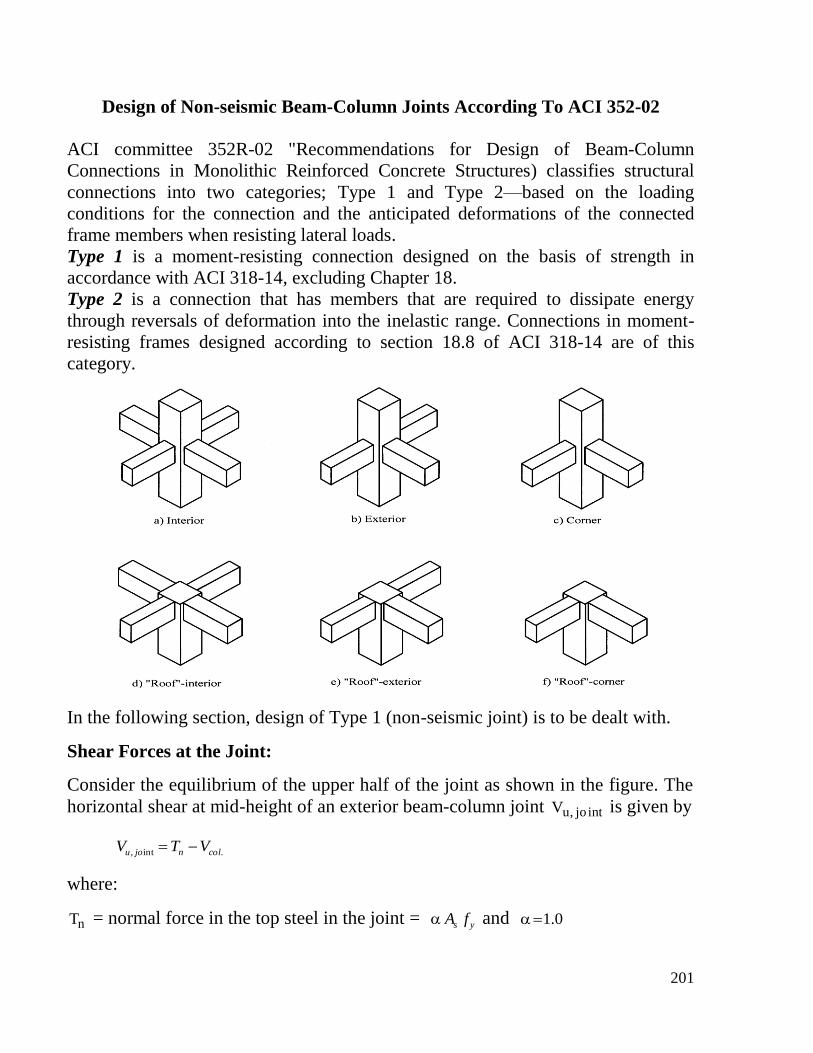
.colV = column shear, which can be evaluated from frame analysis or from the free
body diagram assuming the points of inflection at mid-height of each story.
For an interior beam-column joint, the horizontal shear at mid-height of the joint
intjo,uV is given by
.21int, colnnjou VCTV
Where:
1nT = normal force in the top steel in the joint = ys fA and 0.1
2nC = compressive force in concrete to the other side of the joint
Shear Strength of the Joint:
The nominal shear strength on a horizontal plane at mid-height of the joint is given
by
cjcn hbfV '265.0
The factored shear force on a horizontal plane at mid-height of the joint is to satisfy
the following equation.
nu VV
where:
= constant related to the confinement of the joint
ch = column dimension parallel to the shear force direction
jb = effective width of the joint
203
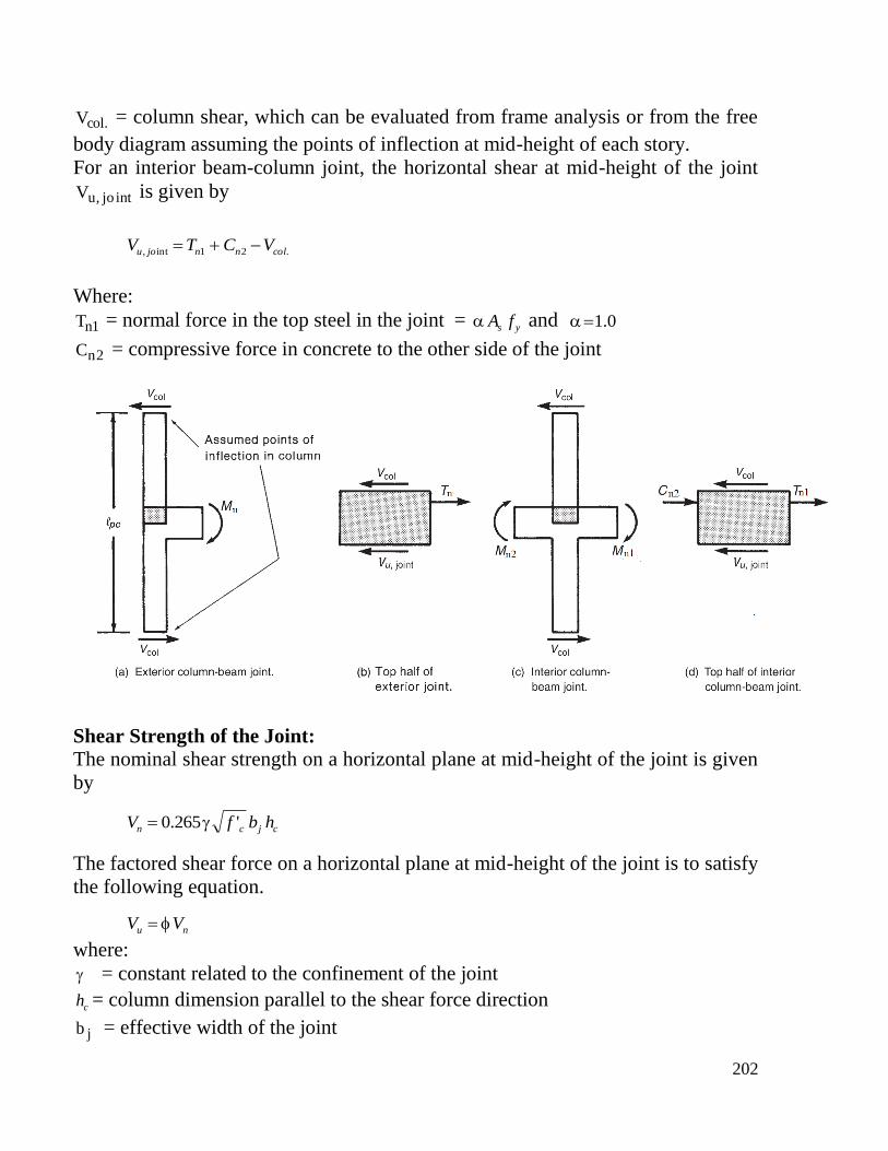
= cbcb hb
bb
2
bb = width of the beam parallel to the applied force
cb = dimension of the column perpendicular to the applied force
= strength reduction factor for shear = 0.75
If the previous equation is not satisfied, either the size of the column needs to be
increased or the shear force transferred to the joint needs to be decreased.
Width of Joint, jb
204
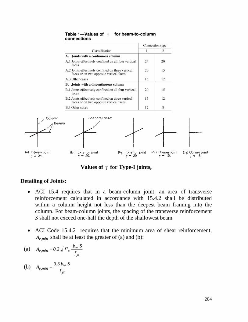
Values of for Type-I joints,
Detailing of Joints:
ACI 15.4 requires that in a beam-column joint, an area of transverse
reinforcement calculated in accordance with 15.4.2 shall be distributed
within a column height not less than the deepest beam framing into the
column. For beam-column joints, the spacing of the transverse reinforcement
S shall not exceed one-half the depth of the shallowest beam.
ACI Code 15.4.2 requires that the minimum area of shear reinforcement,
min,vA shall be at least the greater of (a) and (b):
(a) yt
wcmin,v
f
Sb'f2.0A
(b) yt
wmin,v
f
Sb5.3A
205
ACI 15.2.4 states that a beam-column joint shall be considered to be
"restrained" if the joint is laterally supported on four sides by beams of
approximately equal depth.
Development of longitudinal reinforcement terminating in the joint shall be
in accordance with 25.4.
Beam reinforcement terminating in a non-seismic joint should have 90-deg
hooks with c
bdh
f
dl
318 where dhl is not to be less than bd8 nor less than 15
cm.
The critical section for developing tension in the beam reinforcement is
taken at the face of the joint. If the development length for hooked bars dhl
is not satisfied, either the size of the column will need to be increased or the
amount of shear being transferred to the joint will need to be decreased.
Transverse Reinforcement at the Joint:
ACI committee 352 recommends that non-seismic joints be provided with at
least two layers of transverse reinforcement (ties) between the top and
bottom levels of longitudinal reinforcement in the deepest beam framing
into the joint. For gravity load only maximum spacing is kept to 30 cm and
to 15 cm for non-seismic lateral loads. This requirement is to be ignored if
the joint is considered "restrained" as defined in ACI 15.2.4.
206
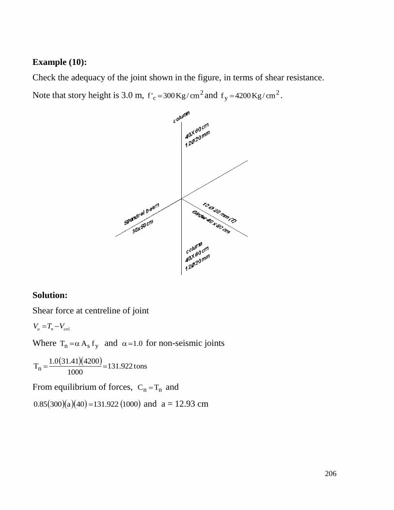
Example (10):
Check the adequacy of the joint shown in the figure, in terms of shear resistance.
Note that story height is 3.0 m, 2c cm/Kg300'f and 2
y cm/Kg4200f .
Solution:
Shear force at centreline of joint
.colnu VTV
Where ysn fAT and 0.1 for non-seismic joints
tons922.131
1000
420041.310.1Tn
From equilibrium of forces, nn TC and
1000922.13140a30085.0 and a = 12.93 cm
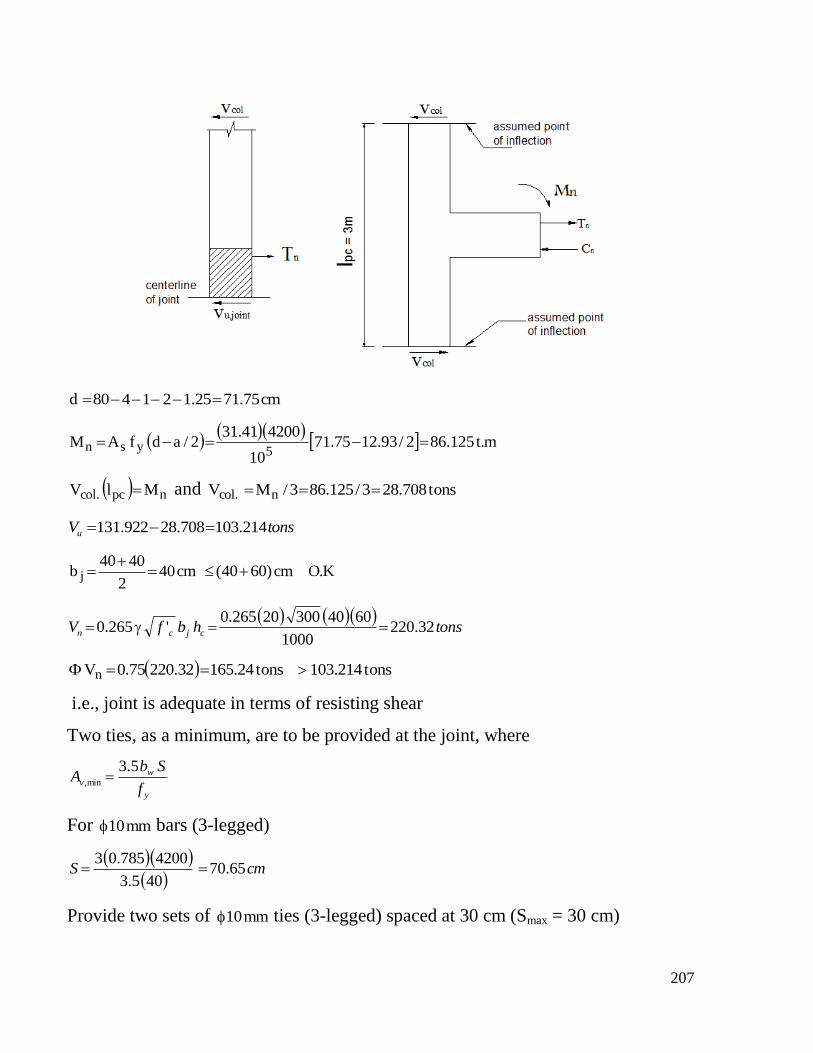
207
cm75.7125.121480d
m.t125.862/93.1275.7110
420041.312/adfAM
5ysn
npc.col MlV and tons708.283/125.863/MV n.col
tonsVu 214.103708.28922.131
K.Ocm)6040(cm402
4040b j
tonshbfV cjcn 32.220
1000
604030020265.0'265.0
tons214.103tons24.16532.22075.0Vn
i.e., joint is adequate in terms of resisting shear
Two ties, as a minimum, are to be provided at the joint, where
y
wv
f
SbA
5.3min,
For mm10 bars (3-legged)
cmS 65.70405.3
4200785.03
Provide two sets of mm10 ties (3-legged) spaced at 30 cm (Smax = 30 cm)

208
Anchorage of top reinforcement in girder:
cm
f
dl
c
bdh 72.36
300
2318
'
318
Available development length = 60 - 4 - 1 - 2 - 2.5 = 50.50 cm > 36.72 cm O.K
209
Joints of Special Moment Frames
The overall integrity of a structure is dependent on the behavior of the beam-
column joint. Degradation of the joint can result in large lateral deformations which
can cause excessive damage or even failure.
Requirements of ACI 18.8 are applicable for joints of special moment frames.
1- Scope:
This section shall apply to beam-column joints of special moment frames
forming part of the seismic-force resisting system.
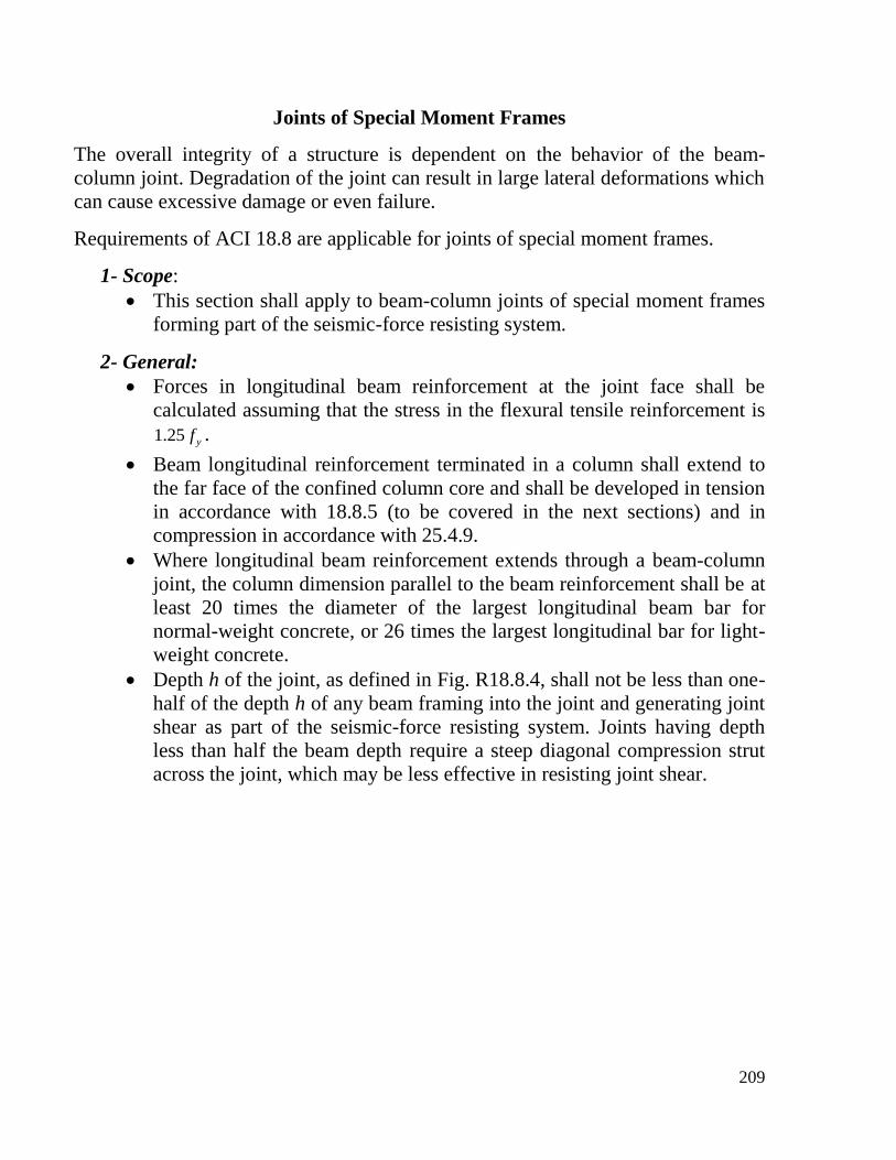
2- General:
Forces in longitudinal beam reinforcement at the joint face shall be
calculated assuming that the stress in the flexural tensile reinforcement is
yf25.1 .
Beam longitudinal reinforcement terminated in a column shall extend to
the far face of the confined column core and shall be developed in tension
in accordance with 18.8.5 (to be covered in the next sections) and in
compression in accordance with 25.4.9.
Where longitudinal beam reinforcement extends through a beam-column
joint, the column dimension parallel to the beam reinforcement shall be at
least 20 times the diameter of the largest longitudinal beam bar for
normal-weight concrete, or 26 times the largest longitudinal bar for light-
weight concrete.
Depth h of the joint, as defined in Fig. R18.8.4, shall not be less than one-
half of the depth h of any beam framing into the joint and generating joint
shear as part of the seismic-force resisting system. Joints having depth
less than half the beam depth require a steep diagonal compression strut
across the joint, which may be less effective in resisting joint shear.
210
3- Transverse Reinforcement:
The transverse reinforcement in a beam-column joint is intended to provide
adequate confinement of the concrete to ensure its ductile behavior and to
allow it to maintain its vertical load-carrying capacity even after spalling of
the outer shell.
ACI 18.8.3 requires transverse reinforcement in a joint regardless of the
magnitude of the calculated shear force.
Transverse reinforcement in a joint shall satisfy 18.7.5.2, 18.7.5.3,
18.7.5.4, and 18.7.5.7, except as permitted in 18.8.3.2
ACI 18.8.3.2 states that where beams frame into all four sides of the joint
and where each beam width is at least three-fourths the column width, the
amount of reinforcement required by 18.7.5.4 shall be permitted to be
reduced by one-half, and the spacing required by 18.7.5.3 shall be
permitted to be increased to 15 cm within the overall depth h of the
shallowest framing beam.
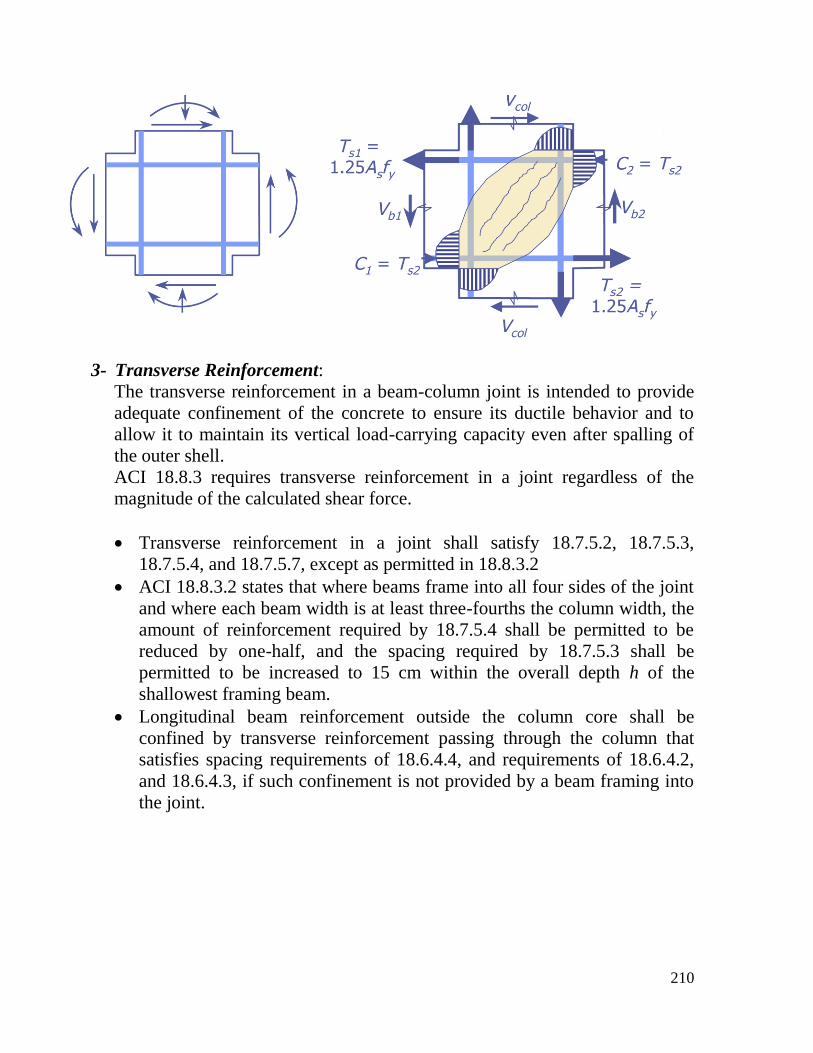
Longitudinal beam reinforcement outside the column core shall be
confined by transverse reinforcement passing through the column that
satisfies spacing requirements of 18.6.4.4, and requirements of 18.6.4.2,
and 18.6.4.3, if such confinement is not provided by a beam framing into
the joint.
211
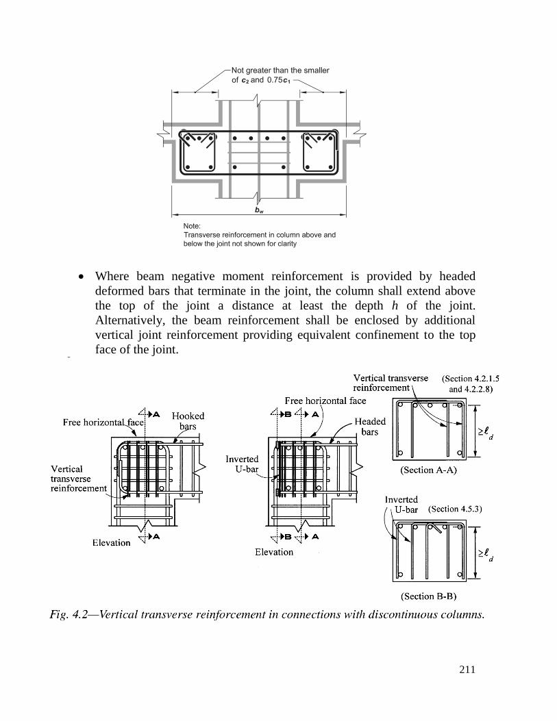
Where beam negative moment reinforcement is provided by headed
deformed bars that terminate in the joint, the column shall extend above
the top of the joint a distance at least the depth h of the joint.
Alternatively, the beam reinforcement shall be enclosed by additional
vertical joint reinforcement providing equivalent confinement to the top
face of the joint.
212
4- Shear Strength:
The nominal shear strength of the joint, Vn is calculated as shown
below:
- For joints confined on all four sides jc Af 3.5
- For joints confined on three faces or on two opposite faces
jc Af 4
- For other cases jc Af 2.3
A joint face is considered to be confined by a beam if the beam
width is at least ¾ of the effective joint width. Extensions of beams
at least one overall beam depth h beyond the joint face are
considered adequate for confining that joint face. Extensions of
beams shall satisfy 18.6.2.1(b), 18.6.3.1, 18.6.4.2, 18.6.4.3, and
18.6.4.4.
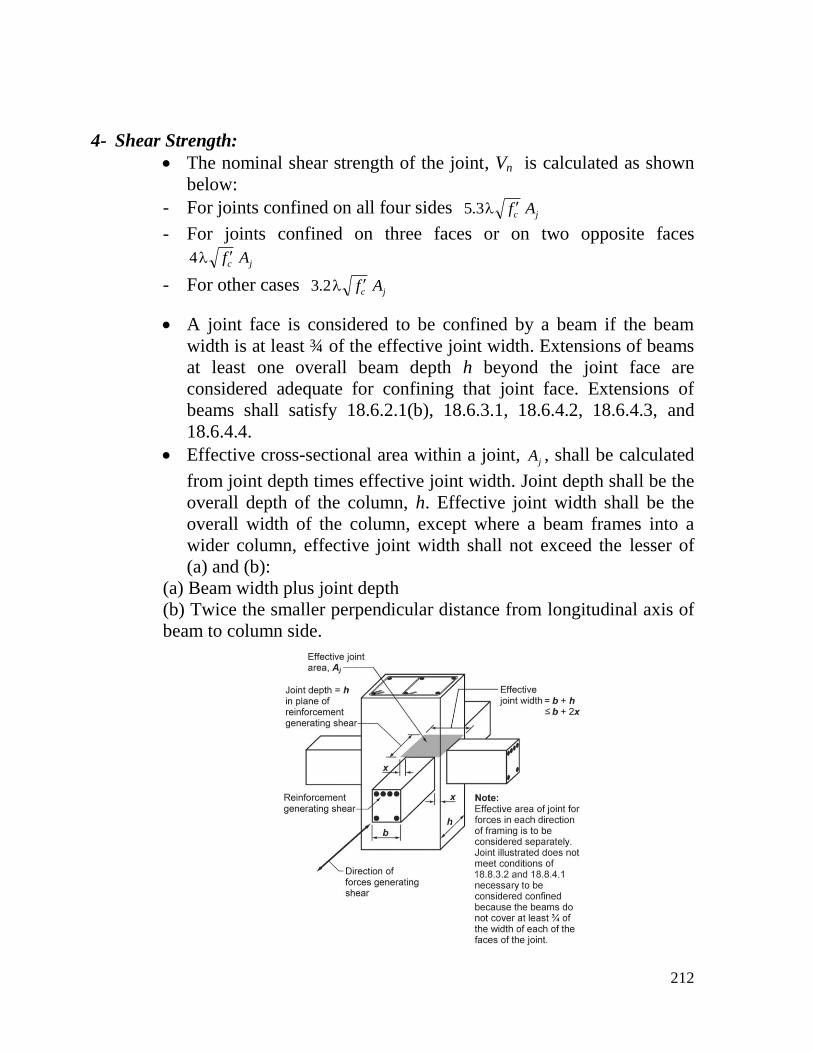
Effective cross-sectional area within a joint, jA , shall be calculated
from joint depth times effective joint width. Joint depth shall be the
overall depth of the column, h. Effective joint width shall be the
overall width of the column, except where a beam frames into a
wider column, effective joint width shall not exceed the lesser of
(a) and (b):
(a) Beam width plus joint depth
(b) Twice the smaller perpendicular distance from longitudinal axis of
beam to column side.
213
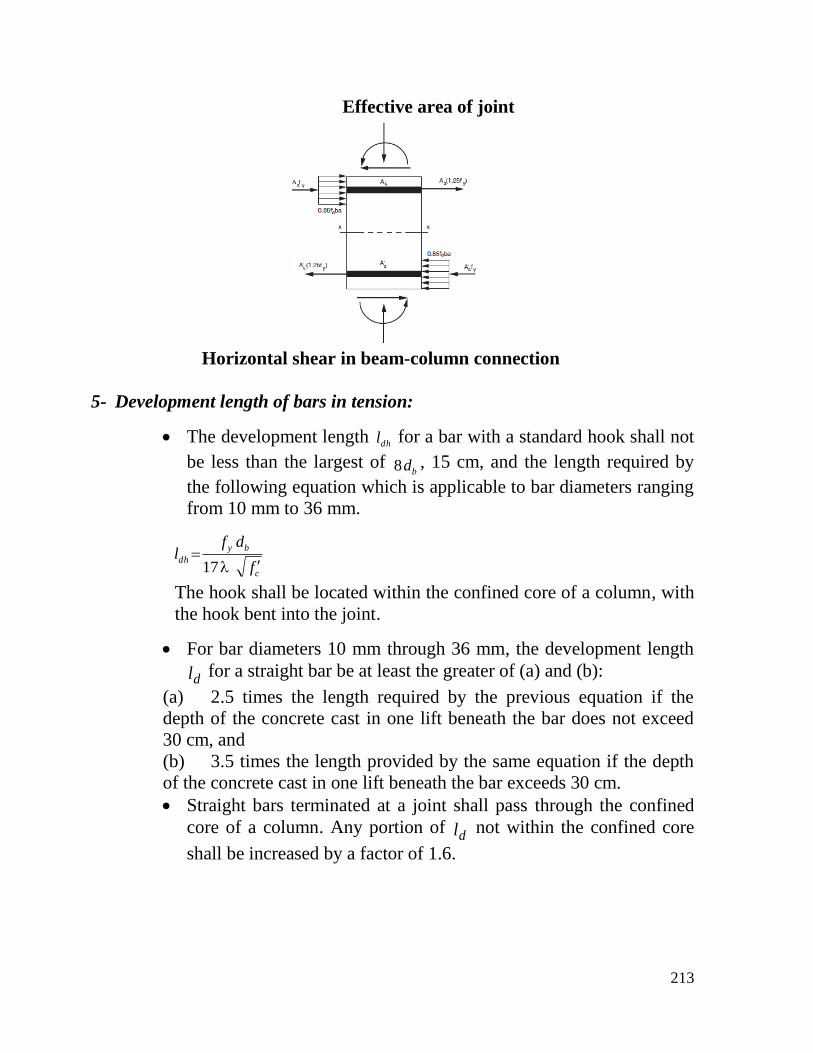
Effective area of joint
Horizontal shear in beam-column connection
5- Development length of bars in tension:
The development length dhl for a bar with a standard hook shall not
be less than the largest of bd8 , 15 cm, and the length required by
the following equation which is applicable to bar diameters ranging
from 10 mm to 36 mm.
c
by
dhf
dfl
17
The hook shall be located within the confined core of a column, with
the hook bent into the joint.
For bar diameters 10 mm through 36 mm, the development length
dl for a straight bar be at least the greater of (a) and (b):
(a) 2.5 times the length required by the previous equation if the
depth of the concrete cast in one lift beneath the bar does not exceed
30 cm, and
(b) 3.5 times the length provided by the same equation if the depth
of the concrete cast in one lift beneath the bar exceeds 30 cm.
Straight bars terminated at a joint shall pass through the confined
core of a column. Any portion of dl not within the confined core
shall be increased by a factor of 1.6.
214
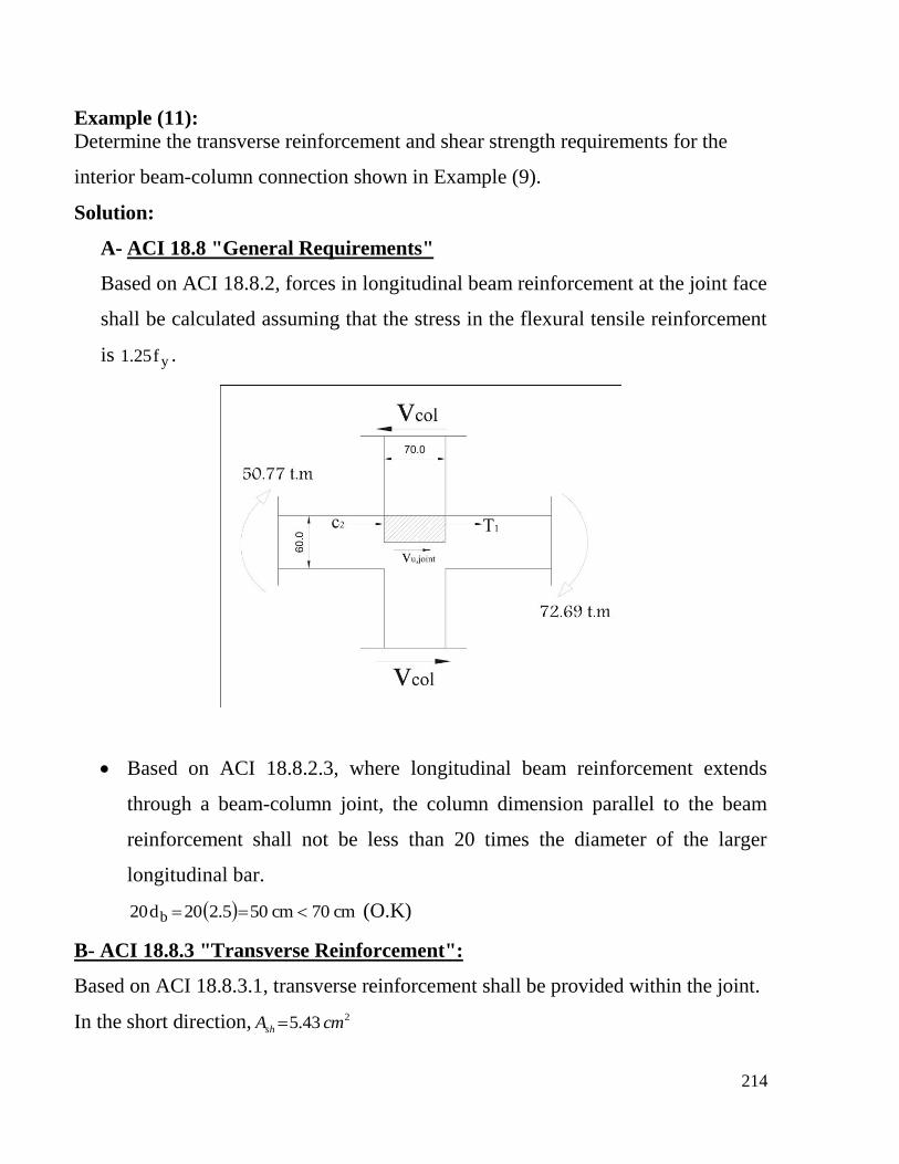
Example (11):
Determine the transverse reinforcement and shear strength requirements for the
interior beam-column connection shown in Example (9).
Solution:
A- ACI 18.8 "General Requirements"
Based on ACI 18.8.2, forces in longitudinal beam reinforcement at the joint face
shall be calculated assuming that the stress in the flexural tensile reinforcement
is yf25.1 .
Based on ACI 18.8.2.3, where longitudinal beam reinforcement extends
through a beam-column joint, the column dimension parallel to the beam
reinforcement shall not be less than 20 times the diameter of the larger
longitudinal bar.
cm70cm505.220d20 b (O.K)
B- ACI 18.8.3 "Transverse Reinforcement":
Based on ACI 18.8.3.1, transverse reinforcement shall be provided within the joint.
In the short direction, 243.5 cmAsh
215
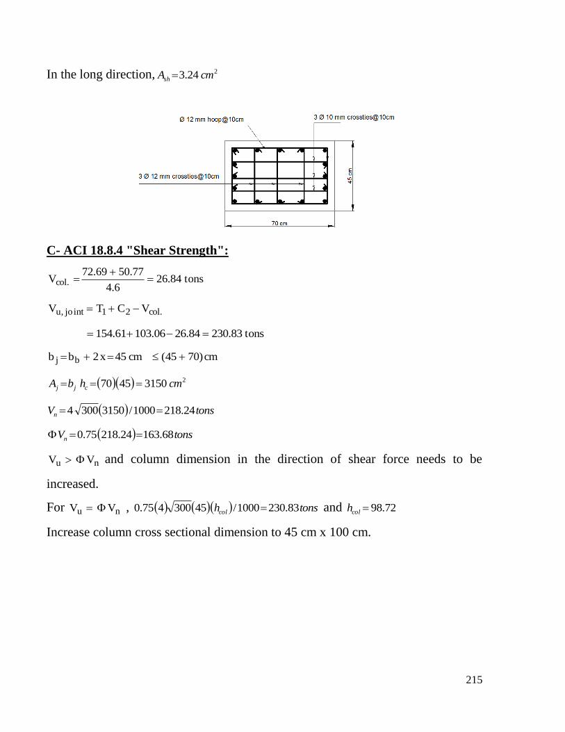
In the long direction, 224.3 cmAsh
C- ACI 18.8.4 "Shear Strength":
tons84.266.4
77.5069.72V .col
.col21intjo,u VCTV
tons83.23084.2606.10361.154
cm)7045(cm45x2bb bj
231504570 cmhbA cjj
tonsVn 24.2181000/31503004
tonsVn 68.16324.21875.0
nu VV and column dimension in the direction of shear force needs to be
increased.
For nu VV , tonshcol 83.2301000/45300475.0 and 72.98colh
Increase column cross sectional dimension to 45 cm x 100 cm.
216
Requirements For Foundations
This section shall apply to foundations resisting earthquake-induced forces or
transferring earthquake-induced forces between structure and ground in structures
assigned to SDC D, E, or F. The requirements for foundations are given in ACI 18.13,
presented below.
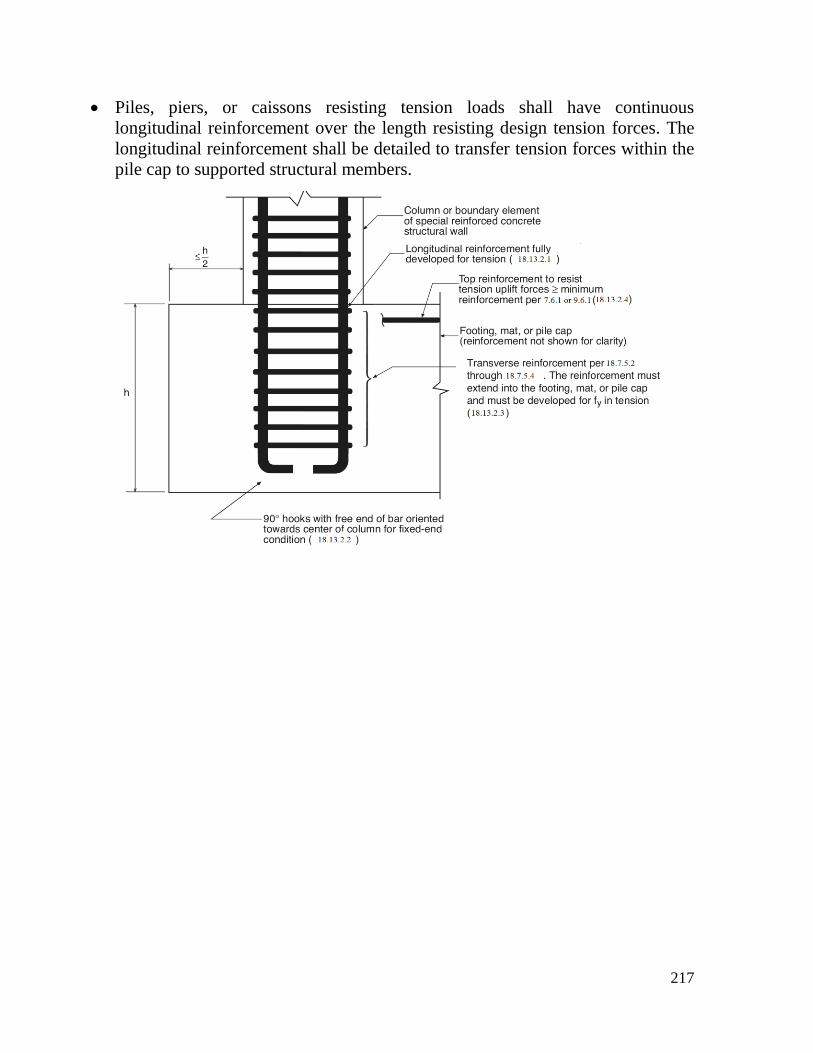
Longitudinal reinforcement of columns and structural walls resisting forces
induced by earthquake effects shall extend into the footing, mat, or pile cap, and
shall be developed for tension at the interface.
Columns designed assuming fixed-end conditions at the foundation, and if
hooks are required, longitudinal reinforcement resisting flexure shall have 90-
degree hooks near the bottom of the foundation with the free end of the bars
oriented toward the center of the column.
Columns or boundary elements of special structural walls that have an edge
within one-half the footing depth from the edge of the footing shall have
transverse reinforcement in accordance with 18.7.5.2 through 18.7.5.4 provided
below the top of the footing. This reinforcement shall extend into the footing,
mat, or pile cap a length equal to the development length calculated for yf in
tension, of the column or boundary element longitudinal reinforcement.
Where earthquake effects create uplift forces in boundary elements of special
structural walls or columns, flexural reinforcement shall be provided in the top
of the footing, mat, or pile cap to resist actions resulting from the factored load
combination, and shall be at least that required by 7.6.1 or 9.6.1.
Grade beams designed to act as horizontal ties between pile caps or footings
shall have continuous longitudinal reinforcement that shall be developed within
or beyond the supported column or anchored within the pile cap or footing at all
discontinuities.
Grade beams designed to act as horizontal ties between pile caps or footings
shall be sized such that the smallest cross-sectional dimension shall be at least
equal to the clear spacing between connected columns divided by 20, but need
not exceed 45 cm. Closed ties shall be provided at a spacing not to exceed the
lesser of one-half the smallest orthogonal cross-sectional dimension and 30 cm.
Grade beams and beams that are part of a mat foundation subjected to flexure
from columns that are part of the seismic-force-resisting system shall be in
accordance with 18.6 (beams of special moment frames).
217
Piles, piers, or caissons resisting tension loads shall have continuous
longitudinal reinforcement over the length resisting design tension forces. The
longitudinal reinforcement shall be detailed to transfer tension forces within the
pile cap to supported structural members.
![BEAM-COLUMN JOINTS STRENGTHENED WITH FRP SYSTEMS … in Seismic... · BEAM-COLUMN JOINTS STRENGTHENED WITH FRP SYSTEMS Ciro FAELLA Full Professor ... Paulay & Priestley [2] (model](https://static.fdocuments.in/doc/165x107/5af2d6ce7f8b9ad061913ad9/beam-column-joints-strengthened-with-frp-systems-in-seismicbeam-column-joints.jpg)