Design of Microwave oven using 8051 micro controller
15
In the partial fulfillment of the course INSTR/EEE 241 – Microprocessor Programming & Interfacing BITS- Pilani K.K.Birla Goa Campus Project by: NAVYA (2011A3PS240G) VAMSI REDDY (2011A8PS346G) OMPRAKASH REDDY (2011A8PS317G) GAUTHAM REDDY (2011A8PS364G)
-
Upload
gautham-reddy -
Category
Education
-
view
357 -
download
18
Transcript of Design of Microwave oven using 8051 micro controller
In the partial fulfillment of the course
INSTR/EEE 241 – Microprocessor Programming & Interfacing
BITS- Pilani K.K.Birla Goa Campus
Project by:
NAVYA (2011A3PS240G) VAMSI REDDY (2011A8PS346G)
OMPRAKASH REDDY (2011A8PS317G) GAUTHAM REDDY (2011A8PS364G)
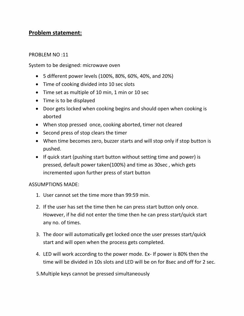
Problem statement:
PROBLEM NO :11
System to be designed: microwave oven
5 different power levels (100%, 80%, 60%, 40%, and 20%)
Time of cooking divided into 10 sec slots
Time set as multiple of 10 min, 1 min or 10 sec
Time is to be displayed
Door gets locked when cooking begins and should open when cooking is
aborted
When stop pressed once, cooking aborted, timer not cleared
Second press of stop clears the timer
When time becomes zero, buzzer starts and will stop only if stop button is
pushed.
If quick start (pushing start button without setting time and power) is
pressed, default power taken(100%) and time as 30sec , which gets
incremented upon further press of start button
ASSUMPTIONS MADE:
1. User cannot set the time more than 99:59 min.
2. If the user has set the time then he can press start button only once.
However, if he did not enter the time then he can press start/quick start
any no. of times.
3. The door will automatically get locked once the user presses start/quick
start and will open when the process gets completed.
4. LED will work according to the power mode. Ex- If power is 80% then the
time will be divided in 10s slots and LED will be on for 8sec and off for 2 sec.
5.Multiple keys cannot be pressed simultaneously
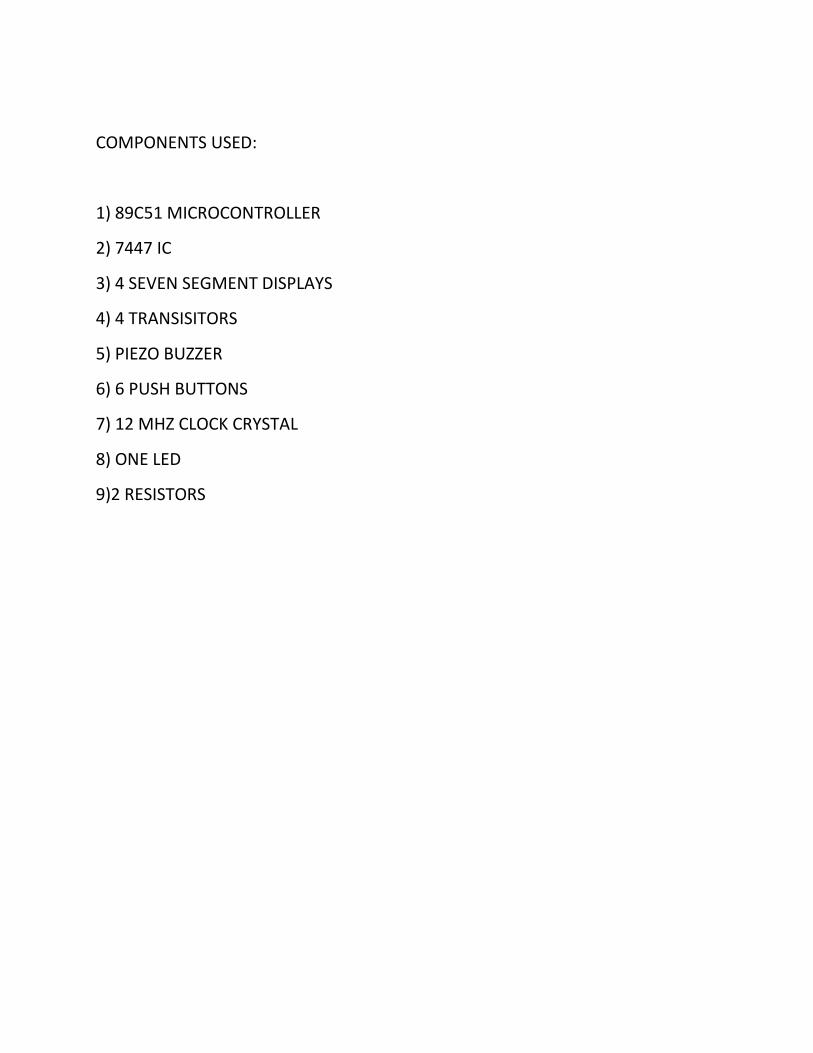
COMPONENTS USED:
1) 89C51 MICROCONTROLLER
2) 7447 IC
3) 4 SEVEN SEGMENT DISPLAYS
4) 4 TRANSISITORS
5) PIEZO BUZZER
6) 6 PUSH BUTTONS
7) 12 MHZ CLOCK CRYSTAL
8) ONE LED
9)2 RESISTORS
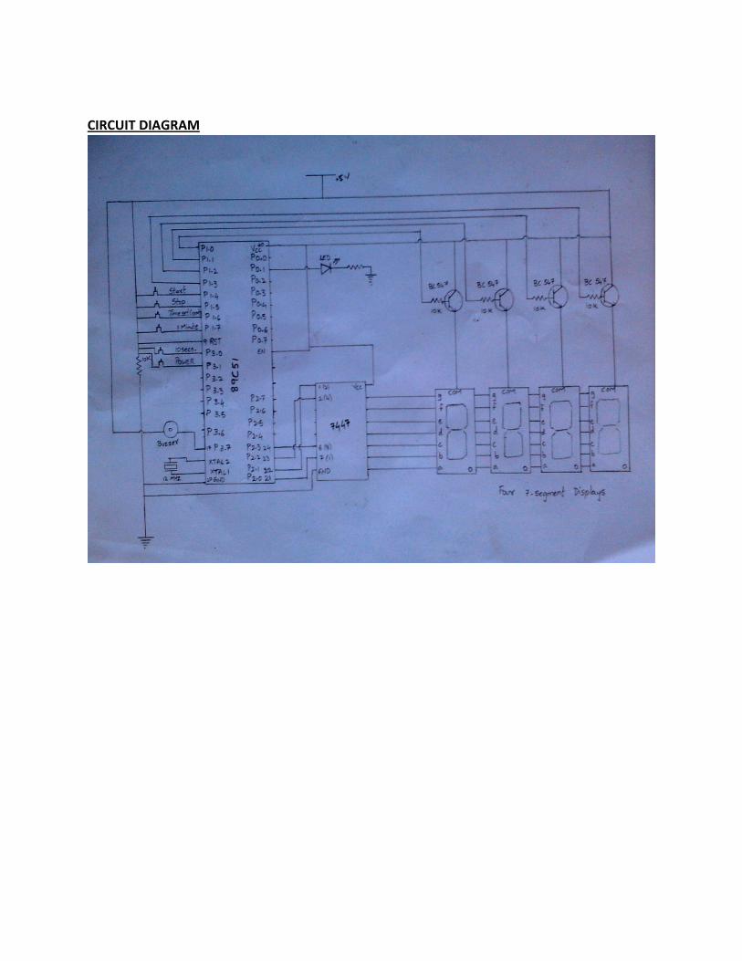
CIRCUIT DIAGRAM
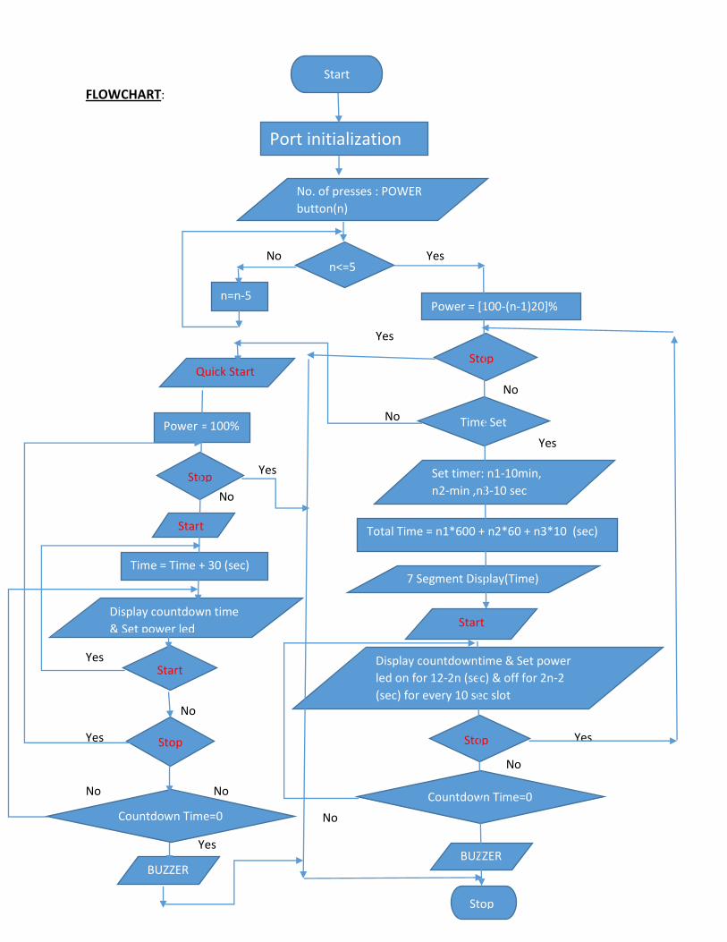
FLOWCHART:
No Yes
Yes
No
No
Yes
Yes
No
Yes
No
Yes Yes
No
No No
No
Yes
Port initialization
No. of presses : POWER
button(n)
n<=5
Power = [100-(n-1)20]% n=n-5
Stop
Time Set
Set timer: n1-10min,
n2-min ,n3-10 sec
Total Time = n1*600 + n2*60 + n3*10 (sec)
7 Segment Display(Time)
Start
Display countdowntime & Set power
led on for 12-2n (sec) & off for 2n-2
(sec) for every 10 sec slot
Stop
Countdown Time=0
BUZZER
Stop
Start
Quick Start
Power = 100%
Stop
Start
Time = Time + 30 (sec)
Display countdown time
& Set power led
Start
Stop
Countdown Time=0
BUZZER
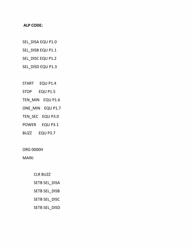
ALP CODE:
SEL_DISA EQU P1.0
SEL_DISB EQU P1.1
SEL_DISC EQU P1.2
SEL_DISD EQU P1.3
START EQU P1.4
STOP EQU P1.5
TEN_MIN EQU P1.6
ONE_MIN EQU P1.7
TEN_SEC EQU P3.0
POWER EQU P3.1
BUZZ EQU P3.7
ORG 0000H
MAIN:
CLR BUZZ
SETB SEL_DISA
SETB SEL_DISB
SETB SEL_DISC
SETB SEL_DISD
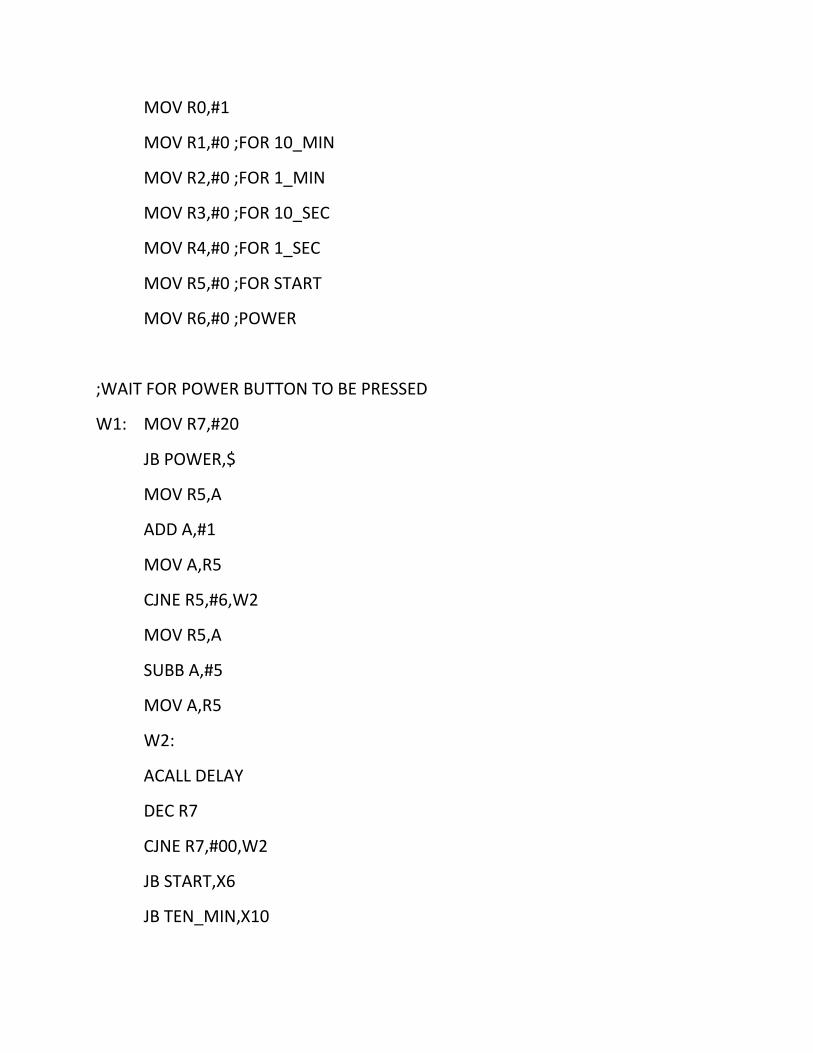
MOV R0,#1
MOV R1,#0 ;FOR 10_MIN
MOV R2,#0 ;FOR 1_MIN
MOV R3,#0 ;FOR 10_SEC
MOV R4,#0 ;FOR 1_SEC
MOV R5,#0 ;FOR START
MOV R6,#0 ;POWER
;WAIT FOR POWER BUTTON TO BE PRESSED
W1: MOV R7,#20
JB POWER,$
MOV R5,A
ADD A,#1
MOV A,R5
CJNE R5,#6,W2
MOV R5,A
SUBB A,#5
MOV A,R5
W2:
ACALL DELAY
DEC R7
CJNE R7,#00,W2
JB START,X6
JB TEN_MIN,X10
JB ONE_MIN,X10
JB TEN_SEC,X10
JMP W1
;SETTING TIME FOR TIMER NORMAL MODE
X10: JB START,X6
MOV R7,#20H
X11:JNB TEN_MIN,X7
SETB SEL_DISA
CLR SEL_DISB
CLR SEL_DISC
CLR SEL_DISD
INC R1
MOV P2,R1
X7:JNB ONE_MIN,X8
CLR SEL_DISA
SETB SEL_DISB
CLR SEL_DISC
CLR SEL_DISD
INC R2
MOV P2,R2
X8:JNB TEN_SEC,X9
CLR SEL_DISA
CLR SEL_DISB
SETB SEL_DISC
CLR SEL_DISD
INC R3
MOV P2,R3
X111: ACALL DELAY
DEC R7
CJNE R7,#00,X111
X9:JMP X10
;SETTING TIME FOR TIMER USING QUICK START MODE
JNB START,X13
INC R5
MOV R7,#20
S1:ACALL DELAY
DEC R7
CJNE R7,#00,S1
X13:
MOV A,R5
MOV B,#2
DIV AB
MOV A,B
CJNE A,#00,X21
MOV A,R3
ADD A,#03
MOV R3,A
X21:
MOV A,R5
MOV B,R0
DIV AB
CJNE A,#1,X22
MOV A,R0
ADD A,#2
MOV R0,A
X22:
MOV A,R5
MOV B,#20
DIV AB
MOV A,B
CJNE A,#00,X23
MOV A,R1
ADD A,#1
X23:
X6:
;RUNNING TIMER
X3:JB STOP,A1
MOV R4,#09
X2:MOV R7,#20
X1:SETB SEL_DISA
CLR SEL_DISB
CLR SEL_DISC
CLR SEL_DISD
MOV A,R1
MOV P2,A
CLR SEL_DISA
SETB SEL_DISB
CLR SEL_DISC
CLR SEL_DISD
MOV A,R2
MOV P2,R2
CLR SEL_DISA
CLR SEL_DISB
SETB SEL_DISC
CLR SEL_DISD
MOV A,R3
MOV P2,A
CLR SEL_DISA
CLR SEL_DISB
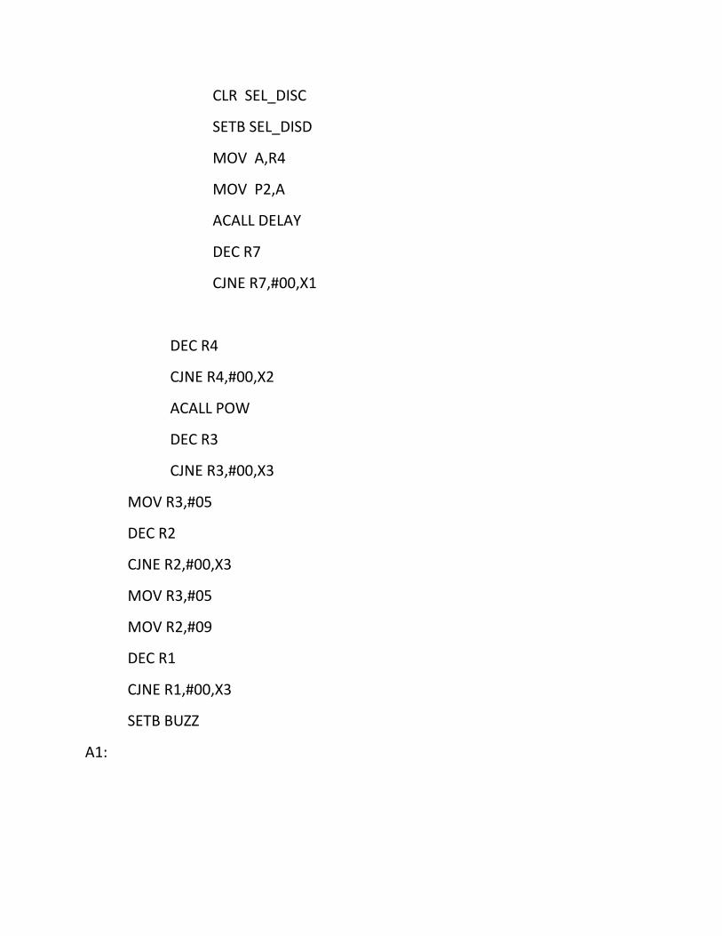
CLR SEL_DISC
SETB SEL_DISD
MOV A,R4
MOV P2,A
ACALL DELAY
DEC R7
CJNE R7,#00,X1
DEC R4
CJNE R4,#00,X2
ACALL POW
DEC R3
CJNE R3,#00,X3
MOV R3,#05
DEC R2
CJNE R2,#00,X3
MOV R3,#05
MOV R2,#09
DEC R1
CJNE R1,#00,X3
SETB BUZZ
A1:
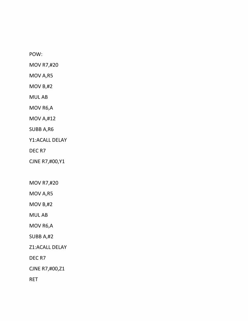
POW:
MOV R7,#20
MOV A,R5
MOV B,#2
MUL AB
MOV R6,A
MOV A,#12
SUBB A,R6
Y1:ACALL DELAY
DEC R7
CJNE R7,#00,Y1
MOV R7,#20
MOV A,R5
MOV B,#2
MUL AB
MOV R6,A
SUBB A,#2
Z1:ACALL DELAY
DEC R7
CJNE R7,#00,Z1
RET
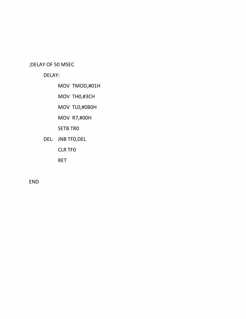
;DELAY OF 50 MSEC
DELAY:
MOV TMOD,#01H
MOV TH0,#3CH
MOV TL0,#0B0H
MOV R7,#00H
SETB TR0
DEL: JNB TF0,DEL
CLR TF0
RET
END