DESIGN OF MACHINING FIXTURE FOR TURBINE ROTOR BLADE · provided with devices for supporting and...
14
IJRET: International Journal of Research in Engineering and Technology eISSN: 2319-1163 | pISSN: 2321-7308 __________________________________________________________________________________________ Volume: 03 Issue: 03 | Mar-2014, Available @ http://www.ijret.org 1 DESIGN OF MACHINING FIXTURE FOR TURBINE ROTOR BLADE C.RadhaMadhavi 1 , B.Ramu 2 , K.Srinivasulu 3 1 Design Engg. in Sri Venkateshwara Mechanical & Electrical India L.td., Hyderabad, AP, India. 2 Asst. prof in Mech Engg, Anurag College of Engineering, Aushapur, Hyderabad, AP, India 3 Associate. prof in Mech Engg, Anurag College of Engineering, Aushapur, Hyderabad, AP, India Abstract This Project presents the Design of Machining Fixture for Gas Turbine Rotor Blade for Machining on VMC (Vertical Machining Centre). Fixture Design consists of High product rate, low manufacturing operation cost. The fixture should be designed in such-a- way that part/product change overtime is very less. The report consists of study of input data from customers like Part drawing and Assembly drawing. The fixture design begins with part modeling, Machining and Analysis of various parts in the fixture assembly using AutoCAD and Solid works, for a analysis COSMOS Software package is used. The actual design begins with study details of project proposal summary from customer. After that machining fixture concept is done. Locating and clamping points are decided. This also includes accessibility, loading and unloading sequence of parts, required material for this fixture is selected, and Fixture is designed at SRI VENKATESWARA MECHANICAL AND ELECTRICALENGINEERING INDUSTRIES, Hyderabad using Industrial application standards. Locating accuracy and machined part quality tested and found that the fixture is as good as any dedicated fixture in production. Keywords: Vertical Machining Centre, AutoCAD and Solid works, COSMOS Software. -----------------------------------------------------------------------***---------------------------------------------------------------------- I .INTRODUCTION This project is intended to design and develop a machining fixture for the gas turbine rotor blade. Machining fixture requires systematic design to clamp, hold and guide the tool during machining process. Using the design data and geometry of the component fixture is designed to hold the part with less time for loading and unloading the part. 1.1. Machining Fixtures The obvious place for Fixtures is in mass production, where large quantity of output offers ample opportunity for recovery of the necessary investment. It is a special tool used for locating and firmly holding a workspace in the proper position during a manufacturing operation. As a general rule it is provided with devices for supporting and clamping the work piece. It is fixed to the machine bed by clamping in such a position that the work in the correct relationship to the machine tool elements. These are the devices, which accelerate the production particularly with 100% interchangeable parts 1.2. Purpose of Machining Fixtures The main purpose of the fixture is to locate the work quickly and accurately, Support it properly and hold it securely, thereby ensuring that all parts produced in the fixture will come out alike within the specified limits. In this way accuracy and interchangeability of the parts are provided. By maintaining or even improving the interchangeability of the parts, a jig or fixture contributes to a considerable reduction in the cost of assembly, maintenance and the subsequent the potential of standard machines and the quality of the parts are produced. One important goal, to design a fixture in such a way as to make it foolproof, and there by contribute to added safety for the operator as well as for the machine tools and other parts being used. 1.3. CLASSIFICATION OF FIXTURES Fixtures are classified according to following factors. Application Based Purpose Based 1. Work holding fixtures 1.Unioverasal fixture 2. Tool holding fixtures 2. Re settable fixtures 3. Fit- up fixtures 3.UCF 4. Gauging fixtures 4. UAF 5. Holding fixtures 5.Specialized fixtures Based On Degree of Mechanization and Automation 1. Hand operated 2. Power operated 3. Semi automatic 4. Automatic Based On Operation 1. Milling fixtures 2. Turning fixtures 3. Grinding fixtures 4. Broaching fixtures 5. Welding fixtures
Transcript of DESIGN OF MACHINING FIXTURE FOR TURBINE ROTOR BLADE · provided with devices for supporting and...

IJRET: International Journal of Research in Engineering and Technology eISSN: 2319-1163 | pISSN: 2321-7308
__________________________________________________________________________________________
Volume: 03 Issue: 03 | Mar-2014, Available @ http://www.ijret.org 1
DESIGN OF MACHINING FIXTURE FOR TURBINE ROTOR BLADE
C.RadhaMadhavi1, B.Ramu
2, K.Srinivasulu
3
1Design Engg. in Sri Venkateshwara Mechanical & Electrical India L.td., Hyderabad, AP, India.
2Asst. prof in Mech Engg, Anurag College of Engineering, Aushapur, Hyderabad, AP, India
3Associate. prof in Mech Engg, Anurag College of Engineering, Aushapur, Hyderabad, AP, India
Abstract This Project presents the Design of Machining Fixture for Gas Turbine Rotor Blade for Machining on VMC (Vertical Machining
Centre). Fixture Design consists of High product rate, low manufacturing operation cost. The fixture should be designed in such-a-
way that part/product change overtime is very less. The report consists of study of input data from customers like Part drawing and
Assembly drawing. The fixture design begins with part modeling, Machining and Analysis of various parts in the fixture assembly
using AutoCAD and Solid works, for a analysis COSMOS Software package is used. The actual design begins with study details of
project proposal summary from customer. After that machining fixture concept is done. Locating and clamping points are decided.
This also includes accessibility, loading and unloading sequence of parts, required material for this fixture is selected, and Fixture is
designed at SRI VENKATESWARA MECHANICAL AND ELECTRICALENGINEERING INDUSTRIES, Hyderabad using Industrial
application standards. Locating accuracy and machined part quality tested and found that the fixture is as good as any dedicated
fixture in production.
Keywords: Vertical Machining Centre, AutoCAD and Solid works, COSMOS Software.
-----------------------------------------------------------------------***----------------------------------------------------------------------
I .INTRODUCTION
This project is intended to design and develop a machining
fixture for the gas turbine rotor blade. Machining fixture
requires systematic design to clamp, hold and guide the tool
during machining process. Using the design data and geometry
of the component fixture is designed to hold the part with less
time for loading and unloading the part.
1.1. Machining Fixtures
The obvious place for Fixtures is in mass production, where
large quantity of output offers ample opportunity for recovery
of the necessary investment. It is a special tool used for
locating and firmly holding a workspace in the proper position
during a manufacturing operation. As a general rule it is
provided with devices for supporting and clamping the work
piece. It is fixed to the machine bed by clamping in such a
position that the work in the correct relationship to the
machine tool elements.
These are the devices, which accelerate the production
particularly with 100% interchangeable parts
1.2. Purpose of Machining Fixtures
The main purpose of the fixture is to locate the work quickly
and accurately, Support it properly and hold it securely,
thereby ensuring that all parts produced in the fixture will
come out alike within the specified limits. In this way
accuracy and interchangeability of the parts are provided.
By maintaining or even improving the interchangeability of
the parts, a jig or fixture contributes to a considerable
reduction in the cost of assembly, maintenance and the
subsequent the potential of standard machines and the quality
of the parts are produced. One important goal, to design a
fixture in such a way as to make it foolproof, and there by
contribute to added safety for the operator as well as for the
machine tools and other parts being used.
1.3. CLASSIFICATION OF FIXTURES
Fixtures are classified according to following factors.
Application Based Purpose Based
1. Work holding fixtures 1.Unioverasal fixture
2. Tool holding fixtures 2. Re settable fixtures
3. Fit- up fixtures 3.UCF
4. Gauging fixtures 4. UAF
5. Holding fixtures 5.Specialized fixtures
Based On Degree of Mechanization and Automation
1. Hand operated
2. Power operated
3. Semi automatic
4. Automatic
Based On Operation
1. Milling fixtures
2. Turning fixtures
3. Grinding fixtures
4. Broaching fixtures
5. Welding fixtures
IJRET: International Journal of Research in Engineering and Technology eISSN: 2319-1163 | pISSN: 2321-7308
__________________________________________________________________________________________
Volume: 03 Issue: 03 | Mar-2014, Available @ http://www.ijret.org 2
6. Assembly fixtures
1.4. Elements of Fixtures
Five considerations are important, of which the first two are
common to both jigs and fixtures, the third applies to jigs only,
and the last two only to fixtures.
a) Location b) Clamping c) Guidance
d) Setting of cutters e) Securing to the machine table
1.5 Advantages of Jigs and Jixtures
Productivity: Jigs & Fixtures eliminate individual marking,
positioning and frequent checking. This reduces operation
time and increase productivity.
Interchangeability: Jigs & Fixtures facilitate uniform quality
in manufacture. There is no need for selective assembly. Any
part of the machine would fit properly in assembly and all
similar components are interchangeable.
Skill Reduction: Jigs & Fixtures simplify locating and
clamping of the work pieces. Tool guiding elements ensure
correct positioning of the tools with respect to the work pieces.
There is no need of skillful setting of the work piece or tool.
Any average person can be trained to use Jigs & Fixtures. The
replacement of a skilled workman with unskilled labor can
effect substantial saving in labor cost.
Cost Reduction: Higher production, reduction in scrap, easy
assembly and savings in labor costs results in substantial
reduction in the cost of work pieces produced with Jigs &
Fixtures.
1.6. Materials Used In Fixtures
Jigs and fixtures are made from a variety of materials some of
them can be hardened to resist wear. It is sometimes necessary
to use non-ferrous metals like Phosphor Bronze or Brass to
reduce wear of mating parts or Nylons or Fiber to prevent
damage to the work piece.
Mild steel: It is the cheapest and most widely used material in
Jigs & Fixtures. It contains less than 0.3%C. Steel En 2 falls in
this category. This steel can be case hardened to 56 HRC. It is
used to make parts which are not subjected to wear and not
highly stressed.
High Tensile Steels: These can be classified into medium
carbon steels with 0.45-0.65%C (En 8, En 9) and alloy steels
like En 24 (40Ni2Cr1Mo28).The tensile strength can be
increased up to 125 kg/mm2 by tempering.
Medium carbon steels are used widely for fasteners, structural
works while HTS are used for high stress applications.
Case Hardening Steels: These can be carburized and case
hardened to provide 0.6-1.5 mm thick, hard exterior (58-62
HRC). 17Mn1Cr95 steels with 1%Mn and 0.95%Cr is widely
used for locating pins, Rest pads etc. These steels are suitable
for parts which require only local hardness on small wearing
surfaces.(Ex: En 353, En 36).
Cast Iron: It contains 2-2.5%C. As it can withstand vibrations
well, it is used widely in milling fixtures. The ingenious
shaping of a casting and the pattern can save a lot of
machining time. Nodular CI is as strong as MS while
Meehanite castings have heat resistance, wear resistance and
corrosion resistance grades.
Nylon and Fiber: These are usually used as soft lining of
clamps to prevent denting or damage to work piece under high
clamping pressure. Nylon or Fiber pads are screwed or stuck
to mild steel clamps.
2. LITERATURE REVIEW
B John J. et al [1] have focused on the design of fixtures for
turbine blades is a difficult problem even for experienced
toolmakers. Turbine blades are characterized by complex
three-dimensional surfaces, high performance materials that
are difficult to manufacture, close tolerance finish
requirements, and high precision machining accuracy. A Al-
Habaibeh.et al [2] have made an attempt to an experimental
design and evaluation of a pin-type universal clamping
system. The clamping system is designed for holding
complex-shaped aerospace components, such as turbine
blades, during machining processes. S. Keith Hargrove et al
[3] has addressed many of the micro issues of automating the
fixture design process using computers. Most of this research
has concentrated on the geometric and kinematic factors that
determine the configuration of a computer-aided fixture design
(CAFXD) system Kailing Li Ran Liu et al [4] discussed
about the research and development of the CAD/CAPP/CAM
and the wide application of CNC technique in the
manufacturing, the traditional method for the jig and fixture
design has not adapted to the demands of complexity and
variety in the practical production with update of products
more and more rapid. Y. Zheng et al [5] has presented a
systematic finite element model to predict the fixture unit
stiffness by introducing nonlinear contact elements on the
contact surface between fixture components. The contact
element includes three independent springs: two in tangential
directions and one in the normal direction of the contact
surface. Strong nonlinearity is caused by possible separation
and sliding between two fixture components. G. Padilla at el
[6] have focused on the organization of the different stages of
the production cycle in order to shorten the time to market.
Within this context, fixture design is crucial: the fixture is the
major link between the machined part and the machine tool
with a strong influence on the part quality, manufacturing

IJRET: International Journal of Research in Engineering and Technology eISSN: 2319-1163 | pISSN: 2321-7308
__________________________________________________________________________________________
Volume: 03 Issue: 03 | Mar-2014, Available @ http://www.ijret.org 3
delays and costs. Production process difficulties are focused
on the fixture design.
It has been an evident case that the Design of Machining
Fixture for Rotor Blade on VMC machine is a research topic
of vitality. A thorough study of literature suggests the usage of
machining fixture for rotary blades. Fixture Design consists of
High product rate, low manufacturing cost operation.
3. FIXTURE DESIGN` FOR TURBINE ROTOR
BLADE
For making the machining fixture design it is required to study
in detail about the component for which fixture is designed
and customer requirements.
Component Description The component is Rotor Blade
Component material is Aluminum Alloy
Composition of Aluminum Alloy
1. Silicon
2. Magnesium
3. Manganese
4. Zinc
5. Chromium
Customer Requirement
The requirement is a machining Fixture.
Single component loading at a time.
Loading and unloading of part using lifting tackles and it
shouldn’t foul with either machine elements or fixture
elements.
Fool proofing while loading component.
Write-up of Interchangeable elements.
Machining Accuracy should be within 50 microns.
3.1 Component & Machine Details
Component : ROTOR BLADE
Material : ALUMINIUM ALLOY
Input Condition : Base Machined
Machine Used : VMC-4AXISTool Taper
: BALL NOSE TOOL
Operation: Face milling, drilling, slot milling.
ROTOR BLADE (A)
ROTOR BLADE (B)
ROTOR BLADE (C)
Fig 3.1
Vertical Machining Centre 4-Axis AS5/A40
Fig 3.2
Table 3.1 Vertical Machining Centre 4 Axis AS5/A40
S.No Parameters Specifications
1 Pallet Size 600 x 400 mm
2 X Traverse 600 mm
3 Y Traverse 350mm
4 Z Traverse 400 mm
5 Spindle RPM 12,000
6 Rapid Traverse 50 m/min
7 Cutting Feed rate 50 m/min
8 Positional Accuracy 0.025mm
9 Indexing 0.3Sec
10 ATC Capacity 20 Tools
11 Tool to Tool 5 sec
12 Chip to Chip 3.8 sec
IJRET: International Journal of Research in Engineering and Technology eISSN: 2319-1163 | pISSN: 2321-7308
__________________________________________________________________________________________
Volume: 03 Issue: 03 | Mar-2014, Available @ http://www.ijret.org 4
13 Power 7Kw
14 Material Removal
Rate 1mm
15 Maximum Tool
Weight 3.5kg
(a) Cutting Tool (Ball Nose Tool)
(b) Cutting Tool Profile (Ball Nose Tool)
Fig 3.3
Conceptual Layout
Fixture is to be designed for face milling, drilling and taping.
The holes are to be drilled on the machined face. Hole sizes
and lengths are given in details in operation sheet. So from the
nature of the operations to be carried out.
By taking all above factors into considerations, we have
generated a conceptual layout of fixture as follows.
1) Part to be loaded on cylindrical pin and Diamond pin with
the help of Rough Guide pins.
2) Part to be butted against rest pads.
3) Hydraulic swing clamps to be used for clamping.
4) Orientation to be kept always on pre machined hole.
5) Part seat check to be accommodated on rest pads.
3.2 LIST OF OPERATIONS MACHINE:
AS5/A40 VMC-4AXIS MACHINE
VMC-CV&CX Profiles Roughing
After clamping the component in the fixture, the fixture is
loaded with help of clamping plug with 0-180 degrees in rotor
axis on the machine. first operation is roughing operation is
done on vmc -4axis machine with 10diameter ball nose tool
on both sides cv and cx profiles for the component convex
operation is done with 0-180 degrees ,after convex operation
fixture is rotated 0-200 degrees for the concave operation.
Heat Treatment
This operation has to do after roughing operation in this
operation component is heated up to 140 degrees centigrade. It
will continuously heated up to 45 mints
VMC-CV & CX Profiles Semi Finishing
Semi finishing operation is done after heat treatment on VMC
-4axis machine with 8 diameter ball nose tool on both sides
cv and cx profiles for the component.
VMC-CV&CX Profiles Finishing
Finishing operation is done after semi finishing operation on
vmc -4axis machine with 8diameter ball nose tool on both
sides cv and cx profiles
3.3 Procedure for Fixture Design
1) Pre-DAP 2) DAP (Design Approval Process)
3) Finalize Layout 4) Detailing
5) Documentation
3.4. MAIN ELEMENTS OF FIXTURE
1. Fixture plate 2. Clamping bracket
3. Bracket-LH 4. Bracket-RH
5. Centre plug-RH 6. Centre plug –LH
7. V- block 8. Thumb screw
9. Grub screw 10. Locating plug
11. Support pin, Tenon, Spl T-nut, Hex soc head cap screw.
Fixture Assembly:
This subassembly is made of different parts of which many are
standard items used for particular application. The main parts
of this assembly are as follows:
(a) Assembly of Fixture with Component (Rotor Blade)
Component Centre plug-LH
Bracket-LH
Fixture plate
Clamping Bracket
Locating plug Bracket-RH
IJRET: International Journal of Research in Engineering and Technology eISSN: 2319-1163 | pISSN: 2321-7308
__________________________________________________________________________________________
Volume: 03 Issue: 03 | Mar-2014, Available @ http://www.ijret.org 5
(b) Assembly of Fixture with Component (Rotor Blade)
Fig 3.4
3.5 CALCULATIONS
3.5.1 For CV & CX Profiles Face Milling:
Available Data:
Component Material: Al Alloy
Cutting Tool: Ball nose tool
Cutting Speed = 3000 rpm
Cutter Dia(D) = Ø10 mm
Width of Cut, (b)= 5 mm
No of Teeth, (Z) = 2
Feed(S) = 1000 mm/min
Notations Used: RPM – Revolutions per Minute
Q – Material Removal Rate,cm3/min
P – Unit Power, kW/ cm3/min
Ts – Torque, N-m
Sm – Feed per min, mm/min
P – Spindle Power, kW
Sz - Feed per Tooth, mm/tooth
Fc – Cutting Force, N or kgf
Speed Calculations (v):
V = πDN/1000 m/min = πx10x3000/1000
= 94.24 m/min
Feed/Tooth (Sz):
Sz= S/ZxSpeed = 1000/2x3000
= 0.16 mm/tooth
Feed per minute(Sm): Sm = Sz x Zx x N = 0.16 x 2 x 3000
= 960 mm/min
Material removal rate(Q): Q = b x d x Sm / 1000 = 5 x 0.5 x 960
= 2.4 cm3/min
Where b = width of cut
d = depth of cut , Sm = Feed /min.
Unit power:
U = 2.4 kw / cm3 / min
Correction factor for flank wear (Kh): = (1.10-1.25)
Correction factor for radial rake angle (Kr): = 0.87
Radial rake angle: = 20 degrees
Power at the spindle (N): N = U x Kh x Kr x Q kw
= 2.4 x 1.15 x 0.87 x 2.4 = 6 kw
Power at the motor (Nel): Nel = N /E = 6/0.8 = 7.5 kw
Tangential cutting force (Pz) : Pz = 6120 x N / V kgf
Pz = 6120 x 6 / 94.24 = 389.64 = 3818.5 N
Torque at spindle ( Ts) : Ts = 975 x N / n = 975 x 6 / 3000
= 1.95 = 19.1 N-M
Clamping force(Fc):
Fc = 3 x cutting force = 3 x 3818.5
= 11455.5 N
3.5.2 For Slot Milling
Available Data:
Component Material: Al Alloy
Cutting Tool:Ball nose tool
Cutting Speed = 2000 rpm
Cutter Dia(D) = Ø5 mm
Depth of Cut,(d)=0.5 mm
Width of Cut, (b)= 2.5 mm
No of Teeth, (Z) = 2
Feed(S) = 1200 mm/min.
Speed Calculations (v):
V = πDN/1000 = πx5x2000/1000
= 31.41 m/min
Feed/ Tooth (Sz):
Sz = S/ZxSpeed = 1200/2x2000
= 0.3 mm/tooth.
Feed per minute(Sm): Sm = Sz x Zx x N = 0.3 x 2 x 2000 cm
3
= 1200 mm/min
Grub screw holes
Centre plug-RH
T- slots Counter bore holes
Centre plug-LH

IJRET: International Journal of Research in Engineering and Technology eISSN: 2319-1163 | pISSN: 2321-7308
__________________________________________________________________________________________
Volume: 03 Issue: 03 | Mar-2014, Available @ http://www.ijret.org 6
Material removal rate (Q): Q = b x d x Sm / 1000 cm
3/min
= 2.5 x 0.5 x 1200 = 1.5 cm3/min
Where b = width of cut
d = depth of cut, Sm = Feed /min
Unit power(U):
U = 2.4 kw / cm3 / min
Correction factor for flank wear (Kh): = (1.10-1.25)
Correction factor for radial rake angle (Kr): = 0.87
Radial rake angle: = 20 degrees
Power at the spindle (N): N = U x Kh x Kr x Q = 2.4 x 1.15 x 0.87 x 1.5
= 3.2 kW
Power at the motor (Nel):
Nel = N /E = 3.2/0.8 = 4.11 kw
Tangential cutting force (Pz) : Pz = 6120 x N / V = 6120 x 3.2 / 31.41
= 623.45 kgf
= 6110.2 N
Torque at spindle ( Ts) :
Ts = 975 x N / n = 975 x 3.2/ 2000
= 15.21 N-M.
Clamping force (Fc):
Fc = 3 x cutting force = 3 x 6110.2
=18330.6 N.
3.5.3. For Hole Drilling
Available Data:
Component Material: Al Alloy
Hardness = 190 – 220 BHN
Speed (N) = 1500 rpm
Drill Dia = Ø2.5 mm
Max Drill Depth = 5 mm
Feed per Revolution = 0.04 -0.06 mm/rev
Notations Used:
kWs – Spindle Power, kW
Tf – Thrust Force, N or kgf
Cutting Speed Calculations(V):
V = π x D x N / 1000 m/min
= π x 2.5 x 1500 /1000 = 11.78 m/min
Material factor[11
]: k = 0.55
Torque: T = 975 x N/ n = 975 x 0.036 /1500
= 0.0234 kgf = 0.229 N
Spindle Power:
N = 1.25 x D2 x k x n (0.056 + 1.5 x s) / 10
5
= 1.25 x (2.5) 2
x 0.55 x 1500 x (0.056 + 1.5 x 0.04) /105
= 0.036 kw
Power at the motor :
Rel = N / E kw = 0.036/ 0.8 = 0.045 kw
= 4.5 kw
Thrust Force:
Tf = 1.16 K D (100 x s)0.85
kgf
= 1.16 x 0.55 x 2.5 x (100 x 0.04)
0.8
= 5.18 kgf = 50.7 N
Clamping force (Fc):
Fc = 3 x cutting force
= 3 x 50.7 = 152.1 N.
3.5.4 For CV& CX profiles finishing milling
Available Data:
Component Material: Al Alloy
Q – Material Removal Rate, cm3/min
Cutting Speed(N) = 4000 rpm
Dia of cutter(D) = Ø8 mm
Max Depth of cut(d) = 0.2 mm
Feed per Revolution(S) =1000 mm/min
Cutting tool =Ball nose tool
No of teeth (Z) =2
Speed Calculations (v)[11]
: V = πDN/1000 m/min = πx8x4000/1000
= 100.53 m/min
Feed/Tooth(Sz):
Sz = S/ZxSpeed = 1000/2x4000
= 0.125 mm/tooth
Feed per minute (Sm):
Sm = Sz x Zx x N mm/min = 0.125 x 2 x 4000
= 1000 mm/min
Material removal rate(Q):
Q = b x d x Sm / 1000 cm3/min
= 4 x 0.2 x 1000 = 0.8 cm3/min
Where, b = width of cut, d = depth of cut
Sm = Feed /min
Unit power:
U = 2 kw /cm3/ min
Correction factor for flank wear(Kh): = (1.10-1.25)
Correction factor for radial rake angle(Kr): = 0.87, Radial
rake angle: = 20 degrees
Power at the spindle (N): N = U x Kh x Kr x Q kw

IJRET: International Journal of Research in Engineering and Technology eISSN: 2319-1163 | pISSN: 2321-7308
__________________________________________________________________________________________
Volume: 03 Issue: 03 | Mar-2014, Available @ http://www.ijret.org 7
= 2.4 x 1.15 x 0.87 x 0.8
= 1.92~2 kw
Power at the motor (Nel):
Nel = N /E = 2/0.8 = 2.5 kw
Tangential cutting force (Pz) :
Pz = 6120 x N / V kgf
= 6120 x 2 / 100.53
= 121.75 kgf = 1193.1 N
Torque at spindle ( Ts) :
Ts = 975 x N / n kgf.m
= 975 x 2 / 4000
= 0.4875 kgf.m = 4.77 N-M
Clamping force(Fc): Fc = 3 x cutting force
= 3 x 1193.1 = 3579.3 N.
3.6 ANALYSIS OF FIXTURE BODY
3.6.1 Selection of Fixture Body
The customer is used vertical machining center for the
machining of component. So that my concept is to keep the
component horizontal to the machine bed. For this purpose, I
select Tombstone structure. This structure should withstand
the cutting forces applied. This Tombstone dimensions should
fall under the work envelope of specific machine and it
could accommodate the component and fixture elements.
Therefore the dimensions of Tombstone (X, Y) 600 X 400.
The width of Tombstone will be decided by the analysis, used
as Solid works COSMOS as below. By this analysis, the
deflection is came 2 microns at maximum force of drilling
(5.18 Kgf) at the centre hole point. This value is within the
safe tolerance of customer requirement.
Table.3.2 Fixture plate Study
A) Material properties
Property Name Value Units Value
Type
Elastic modulus 2.1e+011 N/m^2 Constant
Poisson's ratio 0.28 NA Constant
Shear modulus 7.9e+010 N/m^2 Constant
Mass density 7800 kg/m^3 Constant
Tensile strength 3.9983e+008 N/m^2 Constant
Yield strength 2.2059e+008 N/m^2 Constant
Thermal xpansion
coefficient
1.3e-005 /Kelvin Constant
Thermal
conductivity
43 W/(m.K) Constant
Specific heat 440 J/(kg.K) Constant
(a) Fixture plate-stress plot
(b) Fixture plate-Displacement plot
(c) Fixture plate-strain plot
Fig.3.13. Fixture plate
Fig.3.13 (a) shows the variation of von mises stress. The max
value of von mises stress is (1.80306e+007) and is developed
where there is maximum load. The value of von mises stress is
less, where there is minimum load. Fig.3.13(b) shows the
variation of resultant displacement. The max value of resultant
displacement is2.45948e-006m and is developed where there
is maximum load.
Fig.3.13 (c) shows the variation of equivalent strain. The max
value of equivalent strain is3.92623e-005 and is developed
where there is maximum load. The value of equivalent strain
is less, where there is minimum load.

IJRET: International Journal of Research in Engineering and Technology eISSN: 2319-1163 | pISSN: 2321-7308
__________________________________________________________________________________________
Volume: 03 Issue: 03 | Mar-2014, Available @ http://www.ijret.org 8
B). Study Results of Fixture plate
Name Type Min Location Max Location
Stress1 VON:von Mises
Stress
49616.3
N/m^2
Node: 23474
(-2.29223e-007 mm,
-10.5 mm,
-23.0048 mm)
1.80306e+007
N/m^2
Node: 16675
(8.74987 mm,
49.9996 mm,
-9.50067 mm)
Displacement1 URES: Resultant
Displacement
0 m
Node: 5
(2.79 mm,
-39.8324 mm,
-35 mm)
2.45948e-006 m
Node: 1577
(150 mm,
44.9983 mm,
-0.00174476 mm)
Strain1 ESTRN:
Equivalent Strain
2.279e-007
Element:
6917
(-39.9583 mm,
33.8766 mm,
-24.449 mm)
3.92623e-005
Element: 6602
(8.55571 mm,
52.7547 mm,
-10.1624 mm)
B). Study Results of Bracket-LH
Name Type Min Location Max Location
Stress1 VON: von Mises
Stress
8761.98 N/m^2
Node: 247
(-41.9997 mm,
114.767 mm,
-37.4978 mm)
1.95621e+007
N/m^2
Node: 9307
(7.35617 mm,
4.35072 mm,
37.5001 mm)
Displacement1 URES:Resultant
Displacement
0 m
Node: 127
(-60 mm,
-1.02349e-012 mm,
5.5 mm)
3.32987e-006
m
Node: 8924
(-6.9999 mm,
69.7635 mm,
37.5017 mm)
Strain1 ESTRN:
Equivalent Strain
2.29337e-008
Element: 2970
(-67.0372 mm,27.5372
mm,-35.4297 mm)
5.8501e-005
Element: 8559
(7.62384 mm,
4.79117 mm,35.1563
mm)
Table.3.3 Bracket-LH-Study
A) Material Properties:
Property
Name
Value Units Value
Type
Elastic
modulus
2.1e+011 N/m^2 Constant
Poisson's ratio 0.28 NA Constant
Shear
modulus
7.9e+010 N/m^2 Constant
Mass density 7800 kg/m^3 Constant
Tensile
strength
3.9983e+008 N/m^2 Constant
Yield strength 2.2059e+008 N/m^2 Constant
Thermal
expansion
coefficient
1.3e-005 /Kelvin Constant
Thermal
conductivity
43 W/(m.K) Constant
Specific heat 440 J/(kg.K) Constant
(a) Bracket-LH_Von-Mises Stress Plot
(b) Bracket –LH- Displacement Plot
(c ) Bracket-LH-Strain Plot
Fig 3.14 Bracket-LH

IJRET: International Journal of Research in Engineering and Technology eISSN: 2319-1163 | pISSN: 2321-7308
__________________________________________________________________________________________
Volume: 03 Issue: 03 | Mar-2014, Available @ http://www.ijret.org 9
Fig.3.14 (a) shows the variation of von mises stress. The max
value of von mises stress is1.95621e+007 and is developed
where there is maximum load. The value of von mises stress is
less, where there is minimum load. The maximum load
developed at the bottom of the bracket-LH.
Fig.3.14 (b) shows the variation of resultant displacement. The
max value of resultant displacement is3.32987e-006 and is
developed where there is maximum load.
Fig.3.14 (c) shows the variation of equivalent strain. The max
value of equivalent strain is5.8501e-005 and is developed
where there is maximum load. The value of equivalent strain
is less, where there is minimum load.
Table 3.4 Bracket-RH-Study
A) Material Properties:
Property
Name
Value Units Value
Type
Elastic
modulus
2.1e+011 N/m^2 Constant
Poisson's
ratio
0.28 NA Constant
Shear
modulus
7.9e+010 N/m^2 Constant
Mass density 7800 kg/m^3 Constant
Tensile
strength
3.9983e+008 N/m^2 Constant
Yield
strength
2.2059e+008 N/m^2 Constant
Thermal
expansion
coefficient
1.3e-005 /Kelvin Constant
Thermal
conductivity
43 W/(m.K) Constant
Specific heat 440 J/(kg.K) Constant
(a) Bracket-RH –Stress plot
(b) Bracket-RH-Displacement plot
(c)Bracket-RH strain plot
Fig 3.15 Bracket-RH
Fig.3.15 (a) shows the variation of von mises stress. The max
value of von mises stress is29569.2 and is developed where
there is maximum load. The value of von mises stress is less,
where there is minimum load.
Fig.3.15 (b) shows the variation of resultant displacement. The
max value of resultant displacement is5.11953e-009 m and is
developed where there is maximum load.
Fig.3.15(c) shows the variation of equivalent strain. The max
value of equivalent strain is9.69231e-008 and is developed
where there is maximum load. The value of equivalent strain
is less, where there is minimum load.
Table. 3.5 Clamping Bracket Study
A) Material Properties:
Property
Name
Value Units Value
Type
Elastic
modulus
2.1e+011 N/m^2 Constant
Poisson's
ratio
0.28 NA Constant
Shear
modulus
7.9e+010 N/m^2 Constant
Mass density 7800 kg/m^3 Constant
Tensile
strength
3.9983e+008 N/m^2 Constant
Yield
strength
2.2059e+008 N/m^2 Constant
Thermal
expansion
1.3e-005 /Kelvin Constant
IJRET: International Journal of Research in Engineering and Technology eISSN: 2319-1163 | pISSN: 2321-7308
__________________________________________________________________________________________
Volume: 03 Issue: 03 | Mar-2014, Available @ http://www.ijret.org 10
coefficient
Thermal
conductivity
43 W/(m.K) Constant
Specific heat 440 J/(kg.K) Constant
(a) Clamping Bracket Stress plot
(b) Clamping Bracket-Displacement plot
(C)Clamping Bracket-strain plot
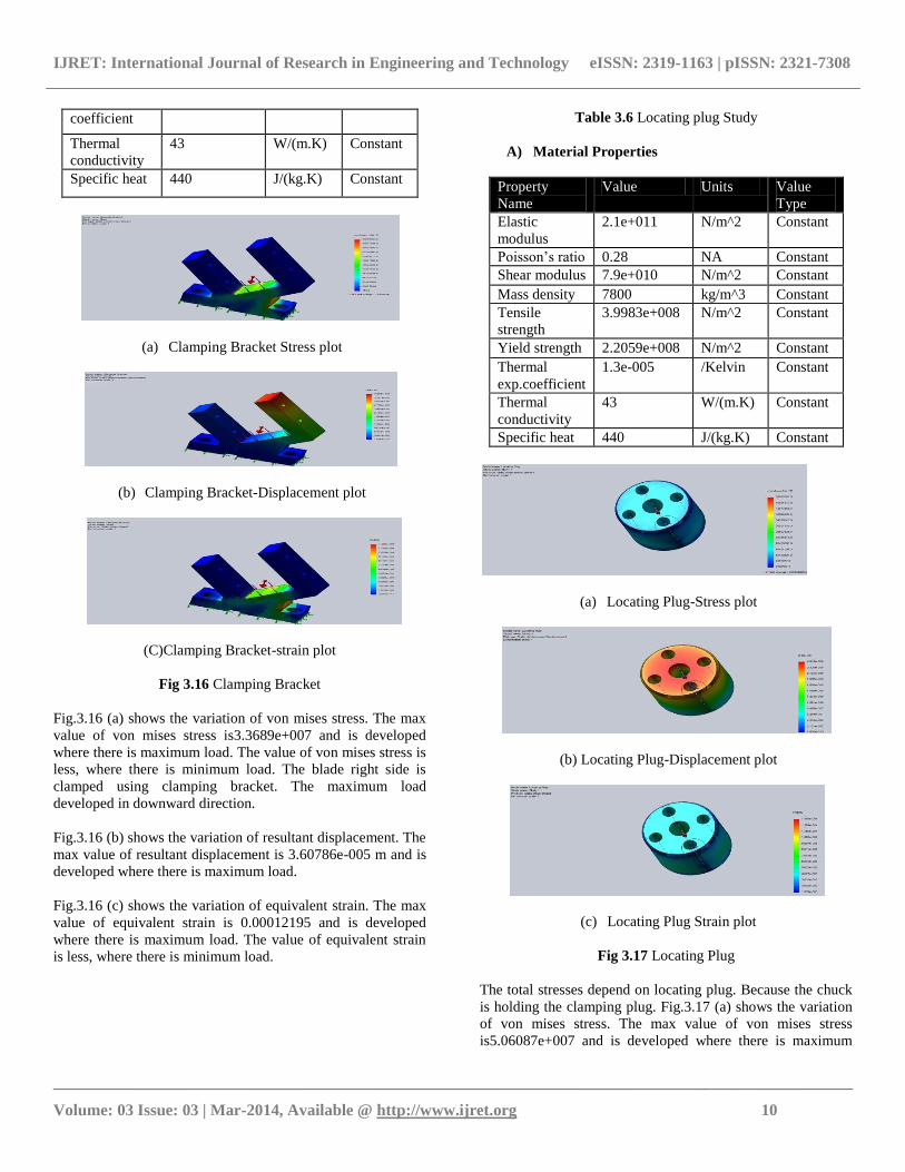
Fig 3.16 Clamping Bracket
Fig.3.16 (a) shows the variation of von mises stress. The max
value of von mises stress is3.3689e+007 and is developed
where there is maximum load. The value of von mises stress is
less, where there is minimum load. The blade right side is
clamped using clamping bracket. The maximum load
developed in downward direction.
Fig.3.16 (b) shows the variation of resultant displacement. The
max value of resultant displacement is 3.60786e-005 m and is
developed where there is maximum load.
Fig.3.16 (c) shows the variation of equivalent strain. The max
value of equivalent strain is 0.00012195 and is developed
where there is maximum load. The value of equivalent strain
is less, where there is minimum load.
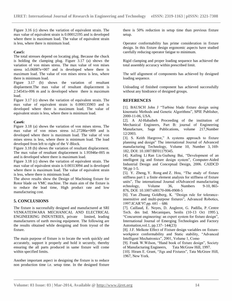
Table 3.6 Locating plug Study
A) Material Properties
Property
Name
Value Units Value
Type
Elastic
modulus
2.1e+011 N/m^2 Constant
Poisson’s ratio 0.28 NA Constant
Shear modulus 7.9e+010 N/m^2 Constant
Mass density 7800 kg/m^3 Constant
Tensile
strength
3.9983e+008 N/m^2 Constant
Yield strength 2.2059e+008 N/m^2 Constant
Thermal
exp.coefficient
1.3e-005 /Kelvin Constant
Thermal
conductivity
43 W/(m.K) Constant
Specific heat 440 J/(kg.K) Constant
(a) Locating Plug-Stress plot
(b) Locating Plug-Displacement plot
(c) Locating Plug Strain plot
Fig 3.17 Locating Plug
The total stresses depend on locating plug. Because the chuck
is holding the clamping plug. Fig.3.17 (a) shows the variation
of von mises stress. The max value of von mises stress
is5.06087e+007 and is developed where there is maximum

IJRET: International Journal of Research in Engineering and Technology eISSN: 2319-1163 | pISSN: 2321-7308
__________________________________________________________________________________________
Volume: 03 Issue: 03 | Mar-2014, Available @ http://www.ijret.org 11
load. The value of von mises stress is less, where there is
minimum load.
Fig.3.17 (b) shows the variation of resultant displacement. The
max value of resultant displacement is 2.54541e-006 m and is
developed where there is maximum load.
Fig.3.17 (c) shows the variation of equivalent strain. The max
value of equivalent strain is 0.000135903 and is developed
where there is maximum load. The value of equivalent strain
is less, where there is minimum load.
Table 3.7. V-Block Study
A) Material Properties
Property
Name
Value Units Value
Type
Elastic
modulus
2.1e+011 N/m^2 Constant
Poisson's
ratio
0.28 NA Constant
Shear
modulus
7.9e+010 N/m^2 Constant
Mass density 7800 kg/m^3 Constant
Tensile
strength
3.9983e+008 N/m^2 Constant
Yield strength 2.2059e+008 N/m^2 Constant
Thermal exp.
coefficient
1.3e-005 /Kelvin Constant
Thermal
conductivity
43 W/(m.K) Constant
Specific heat 440 J/(kg.K) Constant
(a) Support Stress plot
(b) V-Support Displacement plot
(c) V-Support-Strain plot
Fig 3.18 V-Support
Fig.3.18 (a) shows the variation of von mises stress. The max
value of von mises stress is1.27286e+009 and is developed
where there is maximum load. The value of von mises stress is
less, where there is minimum load. The load developed from
left to right of the V-Block.
Fig.3.18 (b) shows the variation of resultant displacement. The
max value of resultant displacement is 1.95946e-005 m and is
developed where there is maximum load.
Fig.3.18 (c) shows the variation of equivalent strain. The max
value of equivalent strain is 0.00313094 and is developed
where there is maximum load. The value of equivalent strain
is less, where there is minimum load.
The above results show the Design of Machining fixture for
Rotor blade on VMC machine. The main aim of the fixture is
to reduce the lead time, High product rate and low
manufacturing cost.
3.6.2 Features of Fixture Assembly
1) Machining fixture:
Machining fixture are used for quick operations to perform
actions such as butting the component against pads, clamping
and orientation of the part. It saves loading time since many
actions are performed simultaneously.It ensures proper
clamping and butting against locating pads due to use of
hydraulic supports and clamps.
2) Repeatability and accuracy of loading and hence
operations to be performed
3) Fool proofing Ensures the part is always loaded in correct
position
4) Reduction in cycle time Due to use of hydraulic elements,
automatic loading tackles, and HMC the cycle time is reduced
to a large extent.
5) Longer life of fixture assembly Long life of the fixture is
ensured due to the use of changeable parts in case of wear and
strength of the parts is also ensured by the use of rigid plates
and castings.
6) Cost Effectiveness Since the cycle time is reduced, the cost
per piece is also reduced.

IJRET: International Journal of Research in Engineering and Technology eISSN: 2319-1163 | pISSN: 2321-7308
__________________________________________________________________________________________
Volume: 03 Issue: 03 | Mar-2014, Available @ http://www.ijret.org 12
7) Manufacturing feasibility The parts are designed by
considering the manufacturing possibilities and also form the
point of mfg costs of the parts.
8) Use of Standard parts Standard parts are used wherever
possible and hence lead time is reduce
B) Study Results of Bracket-RH
Name Type Min Location Max Location
Stress1 VON: von Mises
Stress
16.7346
N/m^2
Node: 12786
(-68 mm,20mm,
-12.3438 mm)
29569.2
N/m^2
Node: 12946
(7.3594 mm,
4.35443 mm,-12.5
mm)
Displacement1 URES: Resultant
Displacement
0 m
Node: 211
(-60 mm,-
1.02002e
-012 mm,5.5 mm)
5.11953e-009
m
Node: 13966
(1.45362 mm,
114.958mm,15 mm)
Strain1 ESTRN:
Equivalent Strain
2.20901e-010
Element: 369
(-67.1043 mm,
19.6489 mm,
-6.52443 mm)
9.69231e-008
Element:
2661
(7.83594 mm,
4.61988 mm,
-11.9517 mm)
B). Study Results of Clamping Bracket
Name Type Min Location Max Location
Stress1 VON: von
Mises Stress
116.104
N/m^2
Node: 11815
(1.66621 mm,
139.405mm,-
1.39032 mm)
3.3689e+007
N/m^2
Node: 10510
(-11.6668mm,19.1233
mm, -49.0009 mm)
Displacement1
URES:
Resultant
Displacement
0 m
Node: 178
(0 mm, -4 mm,
43.5 mm)
3.60786e-005 m
Node: 289
(-25.0003mm,150.114
mm,-14.1611 mm)
Strain1
ESTRN:
Equivalent
Strain
4.98094e-010
Element:
9565
(-22.258
mm,147.077
mm,-
4.8263mm)
0.00012195
Element: 8765
(-7.53101 mm,
17.8654 mm,-47.935
mm,
B). Study Results of Locating Plug
Name Type Min Location Max Location
Stress1 VON: von
Mises Stress
2.39857e+006
N/m^2
Node: 222
(-16.3002 mm,
-3.32448e-007 mm,
10.11 mm)
5.06087e+007
/m^2
Node: 347
(-4.22822 mm,
-16.5174 mm,
0 mm)
Displacement1 URES:
Resultant
Displacement
0 m
Node: 6
(3.05 mm,-5.28276
mm,0 mm)
2.54541e-006 m
Node: 11839
(3.60625mm,-
3.60624
mm,34.9975 mm)
Strain1 ESTRN:
Equivalent
Strain
1.63942e-005
Element: 3964
(-0.333289 mm,
16.8188 mm,
9.87042 mm)
0.000135903
Element: 1897
(16.6995 mm,
4.88732 mm,
0.871527 mm)

IJRET: International Journal of Research in Engineering and Technology eISSN: 2319-1163 | pISSN: 2321-7308
__________________________________________________________________________________________
Volume: 03 Issue: 03 | Mar-2014, Available @ http://www.ijret.org 13
B). Study Results of V-Support
Name Type Min Location Max Location
Stress1 VON: von Mises
Stress
2.21557e+007
N/m^2
Node: 6270
(6.13578 mm,
2.99703 mm,
0.173526 mm)
1.27286e+009
/m^2
Node: 103
(9.99417 mm,
0.000837307 mm,
0.999628 mm)
Displacement1 URES: Resultant
Displacement
0 m
Node: 35
(0 mm,-3.09808
mm,
-1.78868 mm)
1.95946e-005
m
Node: 242
(13.9865 mm,
6.94412
mm,3.99821 mm)
Strain1 ESTRN:
Equivalent Strain
0.000109444
Element:
2572
(2.74185
mm,3.49539
mm,0.260865 m)
0.00313094
Element: 741
(9.96304
mm,0.328087
mm,1.24376 mm)
4. RESULTS AND DISCUSSION
In the present work, the analysis of fixture is carried out using
Solid works COSMOS. The geometric model of the Fixture
elements is drawn by using AutoCAD. The fixture is loaded
with the help of clamping plug with 0-1800 in rotor axis on the
machine.First operation is roughing operation, is done on vmc
-4axis machine with 10diameter ball nose tool on both sides
cv and cx profiles. For the component convex operation is
done with 0-180 degrees, after convex operation fixture is
rotated 0-200 degrees for the concave operation.Semi
finishing operation is done after heat treatment on VMC -4axis
machine with 8 diameter ball nose tool on both sides cv and
cx profiles for the component.Finishing operation is done after
semi finishing operation on vmc -4axis machine with
8diameter ball nose tool on both sides cv and cx profilesSo, all
the operations are carried out by using same fixture at
different control conditions. At ought milling operation the
material removal rate is high. so at that time max stress is
developed on fixture. In finishing operation material removal
rate is less so stress developed at that time less The fixture is
developed at max load condition and min load condition. The
values are calculated to design the fixture using Solid works
COSMOS analysis tool, to find out the stress, strain and
displacement for each and every component of the fixture
assembly. These results are
Case 1:
Figure 3.13 (a) shows the variation of von mises stress. The
max value of von mises stress is (1.80306e+007) and is
developed where there is maximum load. The value of von
mises stress is less, where there is minimum load.
Figure 3.13 (b) shows the variation of resultant
displaement.The max value of resultant displacement
is2.45948e-006m and is developed where there is maximum
load.
Figure 3.13 (c) shows the variation of equivalent strain. The
max value of equivalent strain is3.92623e-005 and is
developed where there is maximum load. The value of
equivalent strain is less, where there is minimum load.
Case 2:
Figure 3.14 (a) shows the variation of von mises stress. The
max value of von mises stress is1.95621e+007 and is
developed where there is maximum load. The value of von
mises stress is less, where there is minimum load. The
maximum load developed at the bottom of the bracket-LH.
Figure 3.14 (b) shows the variation of resultant
displaement.The max value of resultant displacement
is3.32987e-006 and is developed where there is maximum
load.
Figure 3.14 (c) shows the variation of equivalent strain. The
max value of equivalent strain is5.8501e-005 and is developed
where there is maximum load. The value of equivalent strain
is less, where there is minimum load.
Case 3:
Figure 3.15 (a) shows the variation of von mises stress. The
max value of von mises stress is29569.2 and is developed
where there is maximum load. The value of von mises stress is
less, where there is minimum load.
Figure 3.15 (b) shows the variation of resultant
displaement.The max value of resultant displacement
is5.11953e-009 m and is developed where there is maximum
load.
Figure 3.15 (c) shows the variation of equivalent strain. The
max value of equivalent strain is9.69231e-008 and is
developed where there is maximum load. The value of
equivalent strain is less, where there is minimum load.
Case4:
Figure 3.16 (a) shows the variation of von mises stress. The
max value of von mises stress is3.3689e+007 and is developed
where there is maximum load. The value of von mises stress is
less, where there is minimum load. The blade right side is
clamped using clamping bracket. The maximum load
developed in downward direction.
Figure 3.16 (b) shows the variation of resultant
displaement.The max value of resultant displacement is
3.60786e-005 m and is developed where there is maximum
load.
IJRET: International Journal of Research in Engineering and Technology eISSN: 2319-1163 | pISSN: 2321-7308
__________________________________________________________________________________________
Volume: 03 Issue: 03 | Mar-2014, Available @ http://www.ijret.org 14
Figure 3.16 (c) shows the variation of equivalent strain. The
max value of equivalent strain is 0.00012195 and is developed
where there is maximum load. The value of equivalent strain
is less, where there is minimum load.
Case5:
The total stresses depend on locating plug. Because the chuck
is holding the clamping plug. Figure 3.17 (a) shows the
variation of von mises stress. The max value of von mises
stress is5.06087e+007 and is developed where there is
maximum load. The value of von mises stress is less, where
there is minimum load.
Figure 3.17 (b) shows the variation of resultant
displaement.The max value of resultant displacement is
2.54541e-006 m and is developed where there is maximum
load.
Figure 3.17 (c) shows the variation of equivalent strain. The
max value of equivalent strain is 0.000135903 and is
developed where there is maximum load. The value of
equivalent strain is less, where there is minimum load.
Case6:
Figure 3.18 (a) shows the variation of von mises stress. The
max value of von mises stress is1.27286e+009 and is
developed where there is maximum load. The value of von
mises stress is less, where there is minimum load. The load
developed from left to right of the V-Block.
Figure 3.18 (b) shows the variation of resultant displacement.
The max value of resultant displacement is 1.95946e-005 m
and is developed where there is maximum load.
Figure 3.18 (c) shows the variation of equivalent strain. The
max value of equivalent strain is 0.00313094 and is developed
where there is maximum load. The value of equivalent strain
is less, where there is minimum load.
The above results show the Design of Machining fixture for
Rotor blade on VMC machine. The main aim of the fixture is
to reduce the lead time, High product rate and low
manufacturing cost.
5. CONCLUSIONS
The fixture is successfully designed and manufactured at SRI
VENKATESWARA MECHANICAL AND ELECTRICAL
ENGINEERING INDUSTRIES, private limited, leading
manufacturers of earth moving equipment. The following are
the results obtained while designing and from tryout of the
fixture.
The main purpose of fixture is to locate the work quickly and
accurately, support it properly and hold it securely, thereby
ensuring the all parts produced in same fixture will come
within specified limits.
Another important aspect in designing the fixture is to reduce
non production time i.e. setup time. In the designed fixture
there is 50% reduction in setup time than previous fixture
setup.
Operator conformability has prime consideration in fixture
design. In this fixture design ergonomic aspects have studied
carefully reducing operator fatigue to minimum.
Rigid clamping and proper loading sequence has achieved the
total assembly accuracy within prescribed limit.
The self alignment of components has achieved by designed
loading sequence.
Unloading of finished component has achieved successfully
without any hindrance of designed groups.
REFERENCES
[1]. BAUSCH John J “Turbine blade fixture design using
kinematic Methods and Genetic Algorithms”, SPIE Publisher,
2000-11-06, USA.
[2]. A Al-Habaibeh Proceeding of the institution of
Mechanical Engineers, Part B: journal of Engineering
Manufacture, Sage Publications, volume 217,Number
12/2003.
[3]. S. Keith Hargrove,” A systems approach to fixture
planning and design” The international Journal of Advanced
manufacturing Technology, Volume 10, Number 3, 169-
182, DOI: 10.1007/BF01179345.
[4]. Kailing Li Ran Liu Guiheng Bai, “Development of an
intelligent jig and fixture design system”, Computer-Aided
Industrial Design and Conceptual Design, 2006. CAIDCD
'06.pp 1-5.
[5]. Y. Zheng, Y. Rong and Z. Hou, “The study of fixture
stiffness part I: a finite element analysis for stiffness of fixture
units”, The international Journal ofAdvanced manufacturing
echnology, Volume 36, Numbers 9-10, 865-
876, DOI: 10.1007/s00170-006-0908-5
[6]. Yan Zhuang Goldberg, K. “Design rule for tolerance-
insensitive and multi-purpose fixtures”, Advanced Robotics,
1997.ICAR’97.pp. 681 – 686
[7]. Caillaud, E. Noyes, D. Anglerot, G. Padilla, P. Centre
Tech. des Ind. Mecaniques, Senlis (10-13 Oct 1995 ),
“Concurrent engineering: an expert system for fixture design”,
International Journal of Emerging Technologies and Factory
Automation,vol.1, pp.137- 144(23)
[8]. J.F. Melkote Effect of Fixture design variables on fixture-
workpiece conformability and Static stability, “Advanced
Intelligent Mechatronics”, 2001, Volume 1, Como
[9]. Frank W.Wilson, “Hand book of fixture design”, Society
of Manufacturing Engineers, Tata McGraw Hill, 1997.
[10]. Hiram E. Grant, “Jigs and Fixtures”, Tata McGraw Hill,
1967, New York.