Design of M Sub-Mirror Handling Manipulator for LAMOST
8
Design of M B Sub-Mirror Handling Manipulator for LAMOST Heng Zuo [1,2] , Guoping Li [1] , Fanghua Jiang [1] National Astronomical Observatories/Nanjing Institute of Astronomical Optics & Technology, Chinese Academy of Sciences, Nanjing 210042, P. R. China Graduate School of Chinese Academy of Sciences Abstract LAMOST is a quasi-meridian reflecting Schmidt telescope, which consists of a reflecting Schmidt corrector M A , a spherical primary mirror M B and a focal plane. The telescope with its optical axis tilted by an angle of 25° to the horizon tracks the celestial objects by the movements of M A to make the light throughout aim at M B , and M B mirror consists of 37 spherical segments hanged upside down on the truss which tilted by about 25° to the horizon. This paper presents a design of M B sub-mirror segment handling manipulator for LAMOST, carries out a simulation analysis, presents an engineering program and describes the program's design principles and ideas. The manipulator including grab, declutch, elevation, stretch, pitching, rotation, automatic control and several other parts, and the control system can coordinate all these movements so that each segment can be located installed and handled precisely. In the structural design process the stiffness and positioning accuracy problems have been taken full account of. Keywords: LAMOST, Handling Manipulator, Design Scheme, Simulation Analysis 1. Introduction In this fall the whole system of LAMOST should be in place, when final testing will begin, first light will mean the end of a long journey to bring LAMOST into this world. LAMOST is a meridian reflecting Schmidt telescope laid down on the ground with its optical axis fixed in the meridian plane. It consists of a reflecting Schmidt corrector M A at the northern end, a spherical primary mirror M B at the southern end and a focal plane in between. Both the primary mirror and the focal plane are fixed on their ground bases. LAMOST’s eyes include two mirrors composed of 1-meterwide hexagonal segments. The Schmidt corrector M A consists of 24 hexagonal segments and each of them is 1.1m across the diagonal and 25mm in thickness. The primary mirror M B consists of 37 hexagonal segments and each of them is 1.1m across the diagonal and 75mm in thickness. Its focal plane is 1.75m in diameter, corresponding to a 5° field of view, may accommodate as many as 4000 optical fibers. Advanced Optical and Mechanical Technologies in Telescopes and Instrumentation, edited by Eli Atad-Ettedgui, Dietrich Lemke, Proc. of SPIE Vol. 7018, 70183I, (2008) · 0277-786X/08/$18 · doi: 10.1117/12.786900 Proc. of SPIE Vol. 7018 70183I-1
Transcript of Design of M Sub-Mirror Handling Manipulator for LAMOST

Design of MB Sub-Mirror Handling Manipulator
for LAMOST Heng Zuo[1,2], Guoping Li[1], Fanghua Jiang[1]
National Astronomical Observatories/Nanjing Institute of Astronomical Optics & Technology, Chinese Academy of Sciences, Nanjing 210042, P. R. China
Graduate School of Chinese Academy of Sciences
Abstract
LAMOST is a quasi-meridian reflecting Schmidt telescope, which consists of a reflecting Schmidt corrector MA, a spherical primary mirror MB and a focal plane. The telescope with its optical axis tilted by an angle of 25° to the horizon tracks the celestial objects by the movements of MA to make the light throughout aim at MB, and MB mirror consists of 37 spherical segments hanged upside down on the truss which tilted by about 25° to the horizon. This paper presents a design of MB sub-mirror segment handling manipulator for LAMOST, carries out a simulation analysis, presents an engineering program and describes the program's design principles and ideas. The manipulator including grab, declutch, elevation, stretch, pitching, rotation, automatic control and several other parts, and the control system can coordinate all these movements so that each segment can be located installed and handled precisely. In the structural design process the stiffness and positioning accuracy problems have been taken full account of. Keywords: LAMOST, Handling Manipulator, Design Scheme, Simulation Analysis
1. Introduction
In this fall the whole system of LAMOST should be in place, when final testing will begin, first light will mean the end of a long journey to bring LAMOST into this world. LAMOST is a meridian reflecting Schmidt telescope laid down on the ground with its optical axis fixed in the meridian plane. It consists of a reflecting Schmidt corrector MA at the northern end, a spherical primary mirror MB at the southern end and a focal plane in between. Both the primary mirror and the focal plane are fixed on their ground bases. LAMOST’s eyes include two mirrors composed of 1-meterwide hexagonal segments. The Schmidt corrector MA consists of 24 hexagonal segments and each of them is 1.1m across the diagonal and 25mm in thickness. The primary mirror MB consists of 37 hexagonal segments and each of them is 1.1m across the diagonal and 75mm in thickness. Its focal plane is 1.75m in diameter, corresponding to a 5° field of view, may accommodate as many as 4000 optical fibers.
Advanced Optical and Mechanical Technologies in Telescopes and Instrumentation, edited by Eli Atad-Ettedgui,Dietrich Lemke, Proc. of SPIE Vol. 7018, 70183I, (2008) · 0277-786X/08/$18 · doi: 10.1117/12.786900
Proc. of SPIE Vol. 7018 70183I-1

N s M.SphPnm,yMüotFid
FS S.,faeL7Sm
M Reflclin Sbjiijdi PIicAll-k. Mwniig
W,n4Shcld_I______ I KoF%I
liii I
Fig. 1 LAMOST Overview
After the segments are installed, in order to maintain the quality of their reflective surface at the high expectations of the astronomers, they need to be dismounted regularly, washed, treated with acid to remove the aluminum and then freshly coated and then integrated into their mirror cells and attached to the telescope. In the above outlined operation cycle we need special handling tools to complete all the actives. In this paper we designed a special handling manipulator to complete the primary mirror handling.
2. MB Structure The dimension of MB is about 6.7 m × 6 m, it is composed of 37 hexagonal sub-mirrors and each of them is 1.1m across the diagonal and 75mm in thickness, made of Zerodur glass-ceramics, Because the reflecting Schmidt corrector MA tracks the motion of celestial objects, during the observation the primary mirror MB is fixed. At the same time, due to the unconventional optical design, whole MB mirror is face down in 25°. The above two points characterize support system of MB as a very different one from primary mirror of other large telescopes. In order to get good image quality, each sub-mirror should be supported properly and all of them should maintain correct position.
Proc. of SPIE Vol. 7018 70183I-2

'\
II III 'I
Fig. 2 Solid model of Primary Mirror
The special installation method and mechanical properties of LAMOST’s primary mirror MB require that it is always resting on a specially designed support system. The number of supporting point of each segment is 18, which can meet our mirror figure requirement. In our design, we select whiffletrees as the axial support system because they are kinematical, lightweight and compact. Based on common point support methods, 18 points supports can meet our mirror figure requirement for every sub-mirror. A center-hole is used for the center lateral support system on each sub-mirror. The lateral support point is located at the center of gravity of the sub-mirror so there are not overturning moment. The above support systems have been designed and analyzed carefully by FEM, all of them being qualified for earthquakes:
Proc. of SPIE Vol. 7018 70183I-3
\ •••••
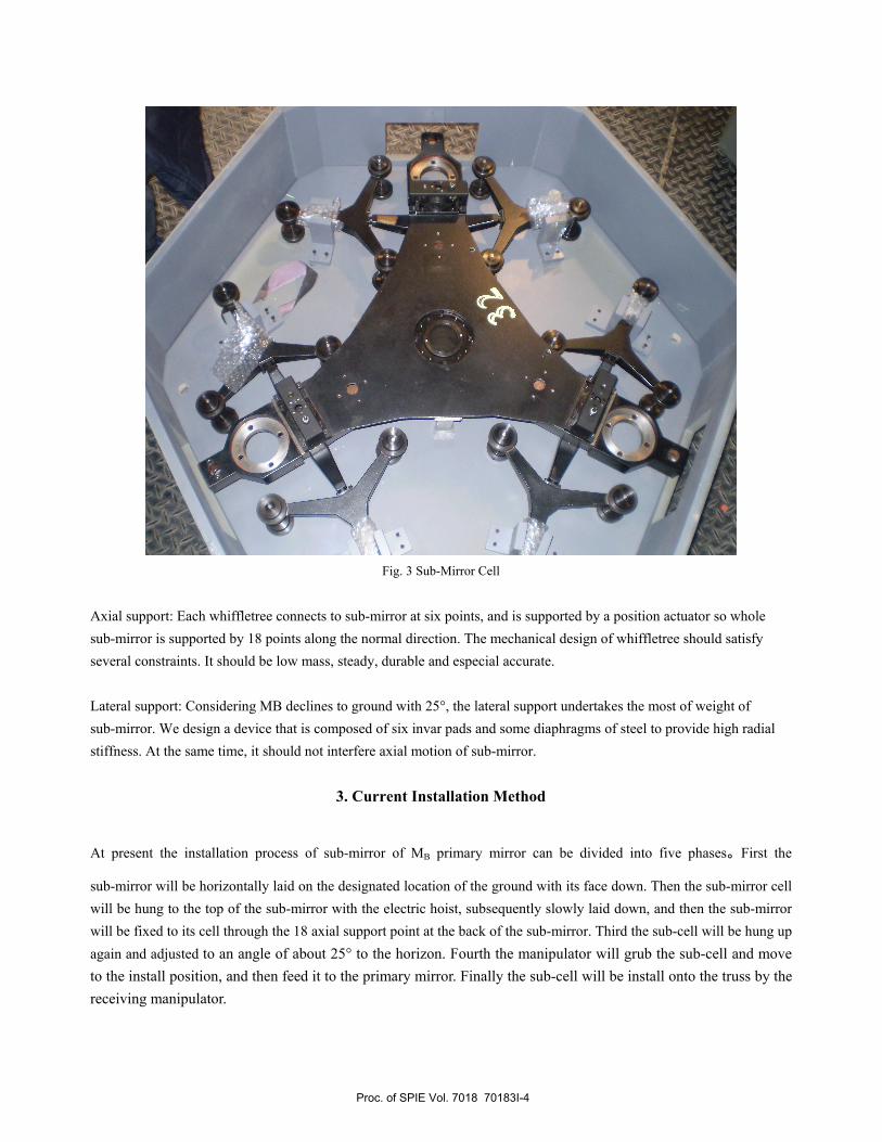
Fig. 3 Sub-Mirror Cell
Axial support: Each whiffletree connects to sub-mirror at six points, and is supported by a position actuator so whole sub-mirror is supported by 18 points along the normal direction. The mechanical design of whiffletree should satisfy several constraints. It should be low mass, steady, durable and especial accurate. Lateral support: Considering MB declines to ground with 25°, the lateral support undertakes the most of weight of sub-mirror. We design a device that is composed of six invar pads and some diaphragms of steel to provide high radial stiffness. At the same time, it should not interfere axial motion of sub-mirror.
3. Current Installation Method
At present the installation process of sub-mirror of MB primary mirror can be divided into five phases。First the
sub-mirror will be horizontally laid on the designated location of the ground with its face down. Then the sub-mirror cell will be hung to the top of the sub-mirror with the electric hoist, subsequently slowly laid down, and then the sub-mirror will be fixed to its cell through the 18 axial support point at the back of the sub-mirror. Third the sub-cell will be hung up again and adjusted to an angle of about 25° to the horizon. Fourth the manipulator will grub the sub-cell and move to the install position, and then feed it to the primary mirror. Finally the sub-cell will be install onto the truss by the receiving manipulator.
Proc. of SPIE Vol. 7018 70183I-4

N
Fig. 4 Current Installation Process
1: Sub-mirror, 2: Sub-mirror Cell, 3: Manipulator
The manipulator currently used is fixed on a platform of a hydraulic lift truck. When the sub-mirror will be installed, the hydraulic lift truck is fist moved to the underneath of the truss, setting aside a certain distance for the fine-tuning, Then the platform is lifted to the designated height to achieve the coarse location of the sub-cell. After the hydraulic lift truck is fixed, in order to make the sub-cell centre aim at the install position centre on the truss we can adjust the horizontal distance through the guide rail on the platform and vertical height through the hoisting jack. Afterwards we rotate the sub-cell round the axis parallel with the primary mirror to make the sub-mirror basic parallel with the primary mirror. Next the manipulator feed to the primary mirror in its vertical direction as far as the receiving manipulator on the truss can grab the sub-cell and install it on the truss. The present manipulator has five degrees of freedom, including: two orthogonal translational DOFs in horizontal plane, one translational DOF in vertical plane and two rotation DOFs.
Fig. 5 Current Handling Manipulator
Proc. of SPIE Vol. 7018 70183I-5
P
In the current installation method, the precise position’s measure is all by works eye estimation, so the whole installation process takes too much time, and in the process there have to be a person on the platform of the hydraulic lift truck, who will operate the manipulator to adjust the sub-cell’s position. He is very dangerous in the high-altitude work. So we plan to design an automatic handling manipulator to avoid these problems in this current installation process.
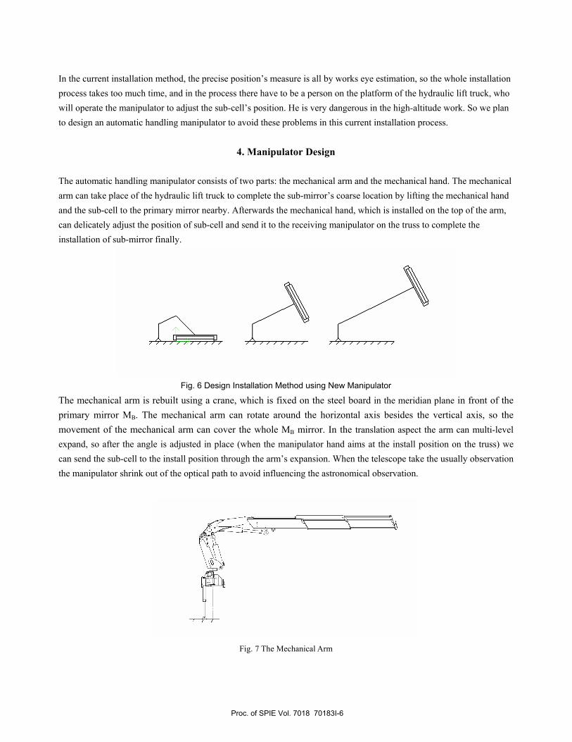
4. Manipulator Design The automatic handling manipulator consists of two parts: the mechanical arm and the mechanical hand. The mechanical arm can take place of the hydraulic lift truck to complete the sub-mirror’s coarse location by lifting the mechanical hand and the sub-cell to the primary mirror nearby. Afterwards the mechanical hand, which is installed on the top of the arm, can delicately adjust the position of sub-cell and send it to the receiving manipulator on the truss to complete the installation of sub-mirror finally.
Fig. 6 Design Installation Method using New Manipulator
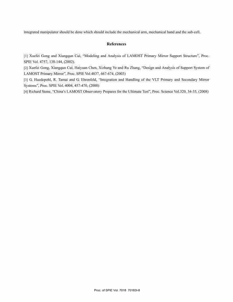
The mechanical arm is rebuilt using a crane, which is fixed on the steel board in the meridian plane in front of the primary mirror MB. The mechanical arm can rotate around the horizontal axis besides the vertical axis, so the movement of the mechanical arm can cover the whole MB mirror. In the translation aspect the arm can multi-level expand, so after the angle is adjusted in place (when the manipulator hand aims at the install position on the truss) we can send the sub-cell to the install position through the arm’s expansion. When the telescope take the usually observation the manipulator shrink out of the optical path to avoid influencing the astronomical observation.
Fig. 7 The Mechanical Arm
Proc. of SPIE Vol. 7018 70183I-6

After the mechanical arm sends the hands to the install position, we use the manipulator hands to delicately adjust the sub-cell’s position and make it parallel with the primary mirror. The manipulator hand is the wrist of the whole handling manipulator, and it can achieve the rotation around the vertical axis, the rotation around the axis parallel with the mirror, the translation of two directions parallel with the mirror and the feed ahead the primary mirror. As the figure, the support axis at the bottom rotates under the motor-driven. A horizon platform with two orthogonal guides is on the top of the vertical axis, and the platform can elevate along the vertical axis in the promotion of the jack. The sub-cell can rotate around the axis parallel with the primary mirror for the push of the thread guide vertical to the sub-mirror.
Fig. 8 Mechanical Hand
The entire manipulator is driven by a hydraulic system. The mechanical arm uses the hydraulic solenoid valve control the break over and the flow rate in the oil circuit. The hydraulic solenoid valve can be remotely controlled, so we can control the accurate volume and the speed of the arm’s rotation and feed by remotely controlling the amount and the rate of the hydraulic oil flowing into the crane’s cylinder by close-cycle control.
5. Conclusion On the basis of above work, we have completed the designing and modeling of the manipulator of LAMOST primary mirror. It seems we have a good model that meets design require, but we think several modification should be done further, including: the connection unit of the mechanical arm and the mechanical hand; Movement accuracy of the mechanical hand’s figure should be improved; With the detail model of the entire manipulator, a FEM analysis of the
Proc. of SPIE Vol. 7018 70183I-7
integrated manipulator should be done which should include the mechanical arm, mechanical hand and the sub-cell.
References
[1] Xuefei Gong and Xiangqun Cui, “Modeling and Analysis of LAMOST Primary Mirror Support Structure”, Proc. SPIE Vol. 4757, 138-144, (2002). [2] Xuefei Gong, Xiangqun Cui, Haiyuan Chen, Xizhang Ye and Ru Zhang, “Design and Analysis of Support System of LAMOST Primary Mirror”, Proc. SPIE Vol.4837, 667-674, (2003) [3] G. Huedepohl, R. Tamai and G. Ehrenfeld, “Integration and Handling of the VLT Primary and Secondary Mirror Systems”, Proc. SPIE Vol. 4004, 457-470, (2000) [4] Richard Stone, “China’s LAMOST Observatory Prepares for the Ultimate Test”, Proc. Science Vol.320, 34-35, (2008)
Proc. of SPIE Vol. 7018 70183I-8