Design of High-Voltage-Tolerant ESD Protection Circuit in ...
10
IEEE TRANSACTIONS ON DEVICE AND MATERIALS RELIABILITY, VOL. 9, NO. 1, MARCH2009 1 Design of High-Voltage-Tolerant ESD Protection Circuit in Low-Voltage CMOS Processes 1 2 Ming-Dou Ker, Fellow, IEEE, and Chang-Tzu Wang, Student Member, IEEE 3 Abstract—Two new electrostatic discharge (ESD) protection 4 design by using only 1 × VDD low-voltage devices for mixed- 5 voltage I/O buffer with 3 × VDD input tolerance are proposed. 6 Two different special high-voltage-tolerant ESD detection circuits 7 are designed with substrate-triggered technique to improve ESD 8 protection efficiency of ESD clamp device. These two ESD de- 9 tection circuits with different design concepts both have effective 10 driving capability to trigger the ESD clamp device on. These ESD 11 protection designs have been successfully verified in two different 12 0.13-μm 1.2-V CMOS processes to provide excellent on-chip ESD 13 protection for 1.2-V/3.3-V mixed-voltage I/O buffers. 14 Index Terms—Electrostatic discharge (ESD), low-voltage 15 CMOS, mixed-voltage I/O, substrate-triggered technique. 16 I. I NTRODUCTION 17 W ITH the decrease of the power supply voltage for 18 low-power applications, the thickness of gate oxide in 19 advanced CMOS technologies has been scaled down to improve 20 circuit performance and to meet the gate-oxide reliability. For 21 whole system integration, the I/O buffers may drive or receive 22 high-voltage signals to communicate with other ICs in the 23 microelectronic system. However, the traditional I/O buffers 24 will suffer from gate-oxide reliability and leakage current path 25 when the I/O buffers receive high-voltage signals. Therefore, 26 the I/O buffers should be designed with consideration on high- 27 voltage tolerance to prevent overstress voltage on the thinner 28 gate oxide of the devices in I/O buffers [1]–[3]. To avoid gate- 29 oxide reliability issue without using additional thick gate oxide 30 process, the stacked NMOS configuration has been widely 31 used in the mixed-voltage I/O buffers. However, the stacked 32 NMOS configuration usually has a lower electrostatic discharge 33 (ESD) level and slow turn-on speed of the parasitic lateral 34 n-p-n device, as compared with the single NMOS [4], [5]. 35 The disadvantages result from the longer base width of the 36 lateral n-p-n BJT in the stacked NMOS devices. Therefore, 37 additional ESD protection design must be provided to protect 38 the stacked NMOS in the mixed-voltage I/O buffer without 39 additional leakage current path [6]. 40 Manuscript received August 27, 2007; revised January 17, 2008 and May 15, 2008. This work was supported in part by the National Science Council (NSC), Taiwan, under Contract NSC 97-2221-E-009-170 and in part by United Microelectronics Corporation, Taiwan. M.-D. Ker is with the Institute of Electronics, National Chiao-Tung Univer- sity, Hsinchu 300, Taiwan, and also with the Department of Electronic Engi- neering, I-Shou University, Kaohsiung 84001, Taiwan (e-mail: mdker@ ieee.org). C.-T. Wang is with the Institute of Electronics, National Chiao-Tung Univer- sity, Hsinchu 300, Taiwan (e-mail: [email protected]). Digital Object Identifier 10.1109/TDMR.2008.2008639 The mixed-voltage I/O buffer to receive 3 × VDD input 41 signals by using only 1 × VDD low-voltage devices without 42 suffering gate-oxide reliability issue has been proposed [7]. 43 Nevertheless, the ESD protection design for such a 3 × 44 VDD-tolerant mixed-voltage I/O buffer was not considered. 45 To achieve a good whole-chip ESD protection scheme for the 46 mixed-voltage I/O applications, it is required to design the low 47 leakage power-rail ESD clamp circuit with only low-voltage 48 devices that can sustain the high power-supply voltage without 49 suffering gate-oxide reliability [8]–[11]. Recently, the ESD 50 protection scheme for the 3.3-V mixed-voltage I/O buffers with 51 1-V/2.5-V dual gate low-voltage devices has been successfully 52 verified in 0.13-μm CMOS process [10]. However, this prior 53 design still needs extra mask-set to implement the thick gate- 54 oxide devices (2.5-V devices). Therefore, how to design an 55 effective ESD protection circuit with only low-voltage devices 56 without suffering gate-oxide reliability for mixed-voltage I/O 57 buffer with 3 × VDD input tolerance is a significant challenge. 58 In this paper, two new high-voltage-tolerant ESD protection 59 designs realized with only 1 × VDD low-voltage devices to 60 protect the mixed-voltage I/O buffer with 3 × VDD input 61 tolerance are proposed [12], [13]. These new ESD protection 62 designs have different efficient ESD detection circuit to trigger 63 on the ESD clamp device, so that the turn-on efficiency of ESD 64 clamp device can be significantly improved. The proposed ESD 65 protection design has been successfully verified in two different 66 0.13-μm 1.2-V CMOS processes. 67 II. ESD PROTECTION SCHEME FOR 3 × VDD-TOLERANT 68 MIXED-VOLTAGE I/O BUFFER 69 To improve ESD robustness of the mixed-voltage I/O inter- 70 faces, an ESD protection concept by using the on-chip ESD 71 bus had been reported [14]. However, in this prior art, the 72 gate-oxide reliability was not considered in its circuit imple- 73 mentation. With consideration on the gate-oxide reliability, the 74 new ESD protection scheme for mixed-voltage I/O buffer with 75 3 × VDD input tolerance is shown in Fig. 1. The circuit 76 design for 3 × VDD-tolerant I/O buffer realized with only 1 × 77 VDD devices has been reported in [7]. In the 3 × VDD I/O 78 buffer, the dynamic gate-bias circuit controls the gate voltages 79 of the stacked NMOS, as shown in Fig. 1. When the I/O 80 buffer receives a logic high (3 × VDD), the gate voltages of 81 the stacked NMOS are biased at VDD and 2 × VDD from 82 left to right, respectively. When operating at other receiving 83 or transmitting modes, the stacked NMOS can also be well 84 biased by the dynamic gate-bias circuit. Therefore, the 3 × 85 VDD I/O buffer can tolerate 3 × VDD input signals without 86 1530-4388/$25.00 © 2008 IEEE
Transcript of Design of High-Voltage-Tolerant ESD Protection Circuit in ...

IEEE TRANSACTIONS ON DEVICE AND MATERIALS RELIABILITY, VOL. 9, NO. 1, MARCH 2009 1
Design of High-Voltage-Tolerant ESD ProtectionCircuit in Low-Voltage CMOS Processes
1
2
Ming-Dou Ker, Fellow, IEEE, and Chang-Tzu Wang, Student Member, IEEE3
Abstract—Two new electrostatic discharge (ESD) protection4design by using only 1 × VDD low-voltage devices for mixed-5voltage I/O buffer with 3 × VDD input tolerance are proposed.6Two different special high-voltage-tolerant ESD detection circuits7are designed with substrate-triggered technique to improve ESD8protection efficiency of ESD clamp device. These two ESD de-9tection circuits with different design concepts both have effective10driving capability to trigger the ESD clamp device on. These ESD11protection designs have been successfully verified in two different120.13-µm 1.2-V CMOS processes to provide excellent on-chip ESD13protection for 1.2-V/3.3-V mixed-voltage I/O buffers.14
Index Terms—Electrostatic discharge (ESD), low-voltage15CMOS, mixed-voltage I/O, substrate-triggered technique.16
I. INTRODUCTION17
W ITH the decrease of the power supply voltage for18
low-power applications, the thickness of gate oxide in19
advanced CMOS technologies has been scaled down to improve20
circuit performance and to meet the gate-oxide reliability. For21
whole system integration, the I/O buffers may drive or receive22
high-voltage signals to communicate with other ICs in the23
microelectronic system. However, the traditional I/O buffers24
will suffer from gate-oxide reliability and leakage current path25
when the I/O buffers receive high-voltage signals. Therefore,26
the I/O buffers should be designed with consideration on high-27
voltage tolerance to prevent overstress voltage on the thinner28
gate oxide of the devices in I/O buffers [1]–[3]. To avoid gate-29
oxide reliability issue without using additional thick gate oxide30
process, the stacked NMOS configuration has been widely31
used in the mixed-voltage I/O buffers. However, the stacked32
NMOS configuration usually has a lower electrostatic discharge33
(ESD) level and slow turn-on speed of the parasitic lateral34
n-p-n device, as compared with the single NMOS [4], [5].35
The disadvantages result from the longer base width of the36
lateral n-p-n BJT in the stacked NMOS devices. Therefore,37
additional ESD protection design must be provided to protect38
the stacked NMOS in the mixed-voltage I/O buffer without39
additional leakage current path [6].40
Manuscript received August 27, 2007; revised January 17, 2008 and May 15,2008. This work was supported in part by the National Science Council(NSC), Taiwan, under Contract NSC 97-2221-E-009-170 and in part by UnitedMicroelectronics Corporation, Taiwan.
M.-D. Ker is with the Institute of Electronics, National Chiao-Tung Univer-sity, Hsinchu 300, Taiwan, and also with the Department of Electronic Engi-neering, I-Shou University, Kaohsiung 84001, Taiwan (e-mail: [email protected]).
C.-T. Wang is with the Institute of Electronics, National Chiao-Tung Univer-sity, Hsinchu 300, Taiwan (e-mail: [email protected]).
Digital Object Identifier 10.1109/TDMR.2008.2008639
The mixed-voltage I/O buffer to receive 3 × VDD input 41
signals by using only 1 × VDD low-voltage devices without 42
suffering gate-oxide reliability issue has been proposed [7]. 43
Nevertheless, the ESD protection design for such a 3 × 44
VDD-tolerant mixed-voltage I/O buffer was not considered. 45
To achieve a good whole-chip ESD protection scheme for the 46
mixed-voltage I/O applications, it is required to design the low 47
leakage power-rail ESD clamp circuit with only low-voltage 48
devices that can sustain the high power-supply voltage without 49
suffering gate-oxide reliability [8]–[11]. Recently, the ESD 50
protection scheme for the 3.3-V mixed-voltage I/O buffers with 51
1-V/2.5-V dual gate low-voltage devices has been successfully 52
verified in 0.13-µm CMOS process [10]. However, this prior 53
design still needs extra mask-set to implement the thick gate- 54
oxide devices (2.5-V devices). Therefore, how to design an 55
effective ESD protection circuit with only low-voltage devices 56
without suffering gate-oxide reliability for mixed-voltage I/O 57
buffer with 3 × VDD input tolerance is a significant challenge. 58
In this paper, two new high-voltage-tolerant ESD protection 59
designs realized with only 1 × VDD low-voltage devices to 60
protect the mixed-voltage I/O buffer with 3 × VDD input 61
tolerance are proposed [12], [13]. These new ESD protection 62
designs have different efficient ESD detection circuit to trigger 63
on the ESD clamp device, so that the turn-on efficiency of ESD 64
clamp device can be significantly improved. The proposed ESD 65
protection design has been successfully verified in two different 66
0.13-µm 1.2-V CMOS processes. 67
II. ESD PROTECTION SCHEME FOR 3 × VDD-TOLERANT 68
MIXED-VOLTAGE I/O BUFFER 69
To improve ESD robustness of the mixed-voltage I/O inter- 70
faces, an ESD protection concept by using the on-chip ESD 71
bus had been reported [14]. However, in this prior art, the 72
gate-oxide reliability was not considered in its circuit imple- 73
mentation. With consideration on the gate-oxide reliability, the 74
new ESD protection scheme for mixed-voltage I/O buffer with 75
3 × VDD input tolerance is shown in Fig. 1. The circuit 76
design for 3 × VDD-tolerant I/O buffer realized with only 1 × 77
VDD devices has been reported in [7]. In the 3 × VDD I/O 78
buffer, the dynamic gate-bias circuit controls the gate voltages 79
of the stacked NMOS, as shown in Fig. 1. When the I/O 80
buffer receives a logic high (3 × VDD), the gate voltages of 81
the stacked NMOS are biased at VDD and 2 × VDD from 82
left to right, respectively. When operating at other receiving 83
or transmitting modes, the stacked NMOS can also be well 84
biased by the dynamic gate-bias circuit. Therefore, the 3 × 85
VDD I/O buffer can tolerate 3 × VDD input signals without 86
1530-4388/$25.00 © 2008 IEEE

2 IEEE TRANSACTIONS ON DEVICE AND MATERIALS RELIABILITY, VOL. 9, NO. 1, MARCH 2009
Fig. 1. Proposed ESD protection scheme for mixed-voltage I/O buffer with 3 × VDD input tolerance realized with only 1 × VDD devices.
gate-oxide reliability issue. The detailed circuit implantation87
to realize such dynamic gate-bias circuit, which can trace the88
voltage level at the I/O pad, can be found in [7].89
To receive the input signals with 3.3-V voltage level, the90
traditional ESD protection with direct diode connection from91
I/O pad to VDD of 1.2 V is forbidden. Therefore, the ESD92
protection circuit is realized with diodes Dp, Dn, D1, ESD bus,93
ESD detection circuit, ESD clamp device, and the power-rail94
ESD clamp circuit between VDD and VSS, as shown in Fig. 1.95
Under positive-to-VSS (PS-mode) ESD stress on I/O pad,96
the ESD current can be discharged through the diode Dp to97
the ESD bus and then through the ESD clamp device [silicon98
control rectifier (SCR)] to the grounded VSS, instead of through99
stacked NMOS in the I/O buffer to ground. Under positive-100
to-VDD (PD-mode) ESD stress on I/O pad, the ESD current101
can be discharged through Dp, ESD bus, and the ESD clamp102
device to VSS power line, and then through the power-rail103
ESD clamp circuit between VDD and VSS to the grounded104
VDD. Under negative-to-VSS (NS-mode) ESD stress on I/O105
pad, the negative ESD current can be discharged through the106
diode Dn in forward-biased condition to the grounded VSS.107
Under negative-to-VDD (ND-mode) ESD stress on I/O pad,108
the negative ESD current can be discharged through Dn to the109
floating VSS power line, and then through the power-rail ESD110
clamp circuit between VDD and VSS to the grounded VDD.111
The four modes of ESD stresses on the mixed-voltage I/O pad112
to VDD or VSS have the corresponding well-designed ESD113
discharging paths in the proposed ESD protection scheme.114
When an ESD stress is applied to the I/O pad, the transient115
voltage-limiting criteria of the 3 × VDD tolerant I/O buffer can116
be expressed as117
Vmax = IESD × RESD + VBD_NMOS (1)
where Vmax is the maximum transient voltage that the 3 ×118
VDD I/O buffer can sustain, IESD is the ESD current, and the119
VBD_NMOS is the transient breakdown voltage of the stacked120
NMOS between the RESD and VSS in Fig. 1. Under the ESD121
stress event, all nodes in the 3 × VDD I/O buffer are floating122
initially. The transient breakdown voltage VBD_NMOS is given 123
by the drain breakdown voltage of the stacked NMOS in the 124
3 × VDD I/O buffer. In order to prevent the ESD current from 125
injecting into the 3 × VDD I/O buffer, the trigger voltage and 126
the clamp voltage of the 3 × VDD-tolerant ESD clamp circuit 127
should be less than Vmax. The clamp voltage of the 3 × VDD- 128
tolerant ESD clamp circuit can be expressed as 129
Vclamp = VD + Vhold + IESD × Ron (2)
where VD is the voltage drop across the diode Dp, Vhold is 130
the holding voltage of the 3 × VDD-tolerant ESD clamp 131
circuit, and Ron is the equivalent turn-on resistance of the diode 132
Dp, parasitic routing resistance, and the 3 × VDD-tolerant 133
ESD clamp circuit. Therefore, RESD should be designed to 134
be slightly greater than some critical value to make sure that 135
Vclamp is less than Vmax. The criterion of RESD can be found as 136
RESD > Ron +VD + Vhold − VBD_NMOS
IESD. (3)
In this paper, VBD_NMOS of ∼7.5 V is measured from the 137
breakdown voltage of the stacked NMOS. For a VD of 0.7 V, 138
Vhold of 3.3 V, and Ron of 3 Ω, the resistance RESD should 139
be greater than 0.4 and 1.7 Ω for 2 kV (IESD of 1.33 A) and 140
4 kV (IESD of 2.66 A) human-body-model (HBM) ESD levels, 141
respectively. Under these criteria, the ESD current is discharged 142
through the proposed ESD protection circuit rather than the 3 × 143
VDD I/O buffer under ESD stress, so that the stacked NMOS in 144
the 3 × VDD I/O buffer can be safely protected by the proposed 145
ESD protection scheme in Fig. 1. 146
The power-rail ESD clamp circuit between VDD and VSS 147
can be realized by the traditional RC-based ESD detection 148
circuit [15]. The SCR device, which is composed of the cross- 149
coupled n-p-n and p-n-p BJTs with regenerative feedback, with 150
a low holding voltage can sustain a high ESD level within 151
a small silicon area in CMOS technology [16]. However, the 152
main concerns of SCR device as the ESD clamp device are 153
the slow turn-on speed, high switching voltage, and latchup 154
issue. To solve the latchup issue, several diodes are added in 155

KER AND WANG: DESIGN OF HIGH-VOLTAGE-TOLERANT ESD PROTECTION CIRCUIT 3
Fig. 2. Device structure of the ESD clamp device composed of substrate- triggered SCR device with diodes in series.
series with SCR as the ESD clamp device to increase its overall156
holding voltage for such (3.3-V) mixed-voltage I/O buffer [17].157
Because these two ESD protection design were implemented158
in two different foundries, the electrical characteristic of SCR159
devices used as ESD clamp device were quite different. The160
holding voltage of SCR device is dominated by the doping pro-161
files correlated with the process of each foundry, and therefore162
the numbers of diodes added in series with SCR for two ESD163
clamp circuit are different to avoid the latchup issue. In this164
paper, three (two) diodes are added with SCR in series to in-165
crease its overall holding voltage to approximately 4 V for such166
3.3-V tolerant ESD clamp circuit A (B). The holding voltage a167
little higher than 3.3 V is used to overcome overshooting supply168
voltage. The device structure of the ESD clamp device used in169
these work is shown in Fig. 2. The purpose of the additional170
N-well region under the N+ diffusion at the cathode of the171
SCR device with the substrate-triggered technique is to further172
enhance the turn-on speed of the SCR device for better turn-173
on efficiency, because that can increase the equivalent substrate174
resistance (Rsub) in this device structure.175
To avoid the ESD damage on I/O buffer before ESD clamp176
device is turned on, the substrate-triggered technique is used177
to quickly trigger on the ESD clamp device. Because ESD bus178
line will be biased at 3.3 V through the diode Dp when 3.3-V179
input signals reach to the I/O pad, the ESD detection circuit180
connected between ESD bus and VSS must sustain the high-181
voltage (3.3 V) stress during normal circuit operating condition.182
Some ESD detection circuits proposed to increase the turn-183
on speed of SCR device will suffer gate-oxide reliability issue184
under 3.3-V bias with only 1.2-V low-voltage devices [18].185
Therefore, how to design a turn-on-efficient ESD detection186
circuit with only 1.2-V devices to sustain 3.3-V bias becomes a187
quite significant challenge to this 1.2/3.3-V mixed-voltage I/O188
buffer.189
III. 3 × VDD-TOLERANT ESD CLAMP CIRCUITS190
During normal circuit operating condition with 1.2-V VDD191
power supply and grounded VSS, when a 3 × VDD (3.3-V)192
input signal is applied to the I/O pad, the voltage level at193
the internal ESD bus will be charged up to 3.3 V through the194
diode Dp connected between I/O pad and ESD bus. For the195
convenience of easily describing the circuit operation of the 3 ×196
VDD-tolerant ESD clamp circuit with HSPICE simulations, the197
ESD bus is treated as an external 3.3 V power supply in this198
section.199
Fig. 3. Circuit implementation of the 3 × VDD-tolerant ESD clamp circuit Arealized with 1 × VDD devices.
A. 3 × VDD-Tolerant ESD Clamp Circuit A 200
The ESD clamp circuit that can be operated under 3.3-V 201
bias with only 1.2-V low-voltage devices is shown in Fig. 3. 202
Under normal circuit operating condition, the diode-connected 203
PMOS (Mp1 ∼ Mp3) are used as the voltage divider to bias the 204
substrate driver (Mn1, Mp4, and Mp5) of the ESD detection 205
circuit, where a deep N-well is used in Mn1 to avoid the gate- 206
oxide overstress between gate and bulk. The NMOS (Mn2) is 207
used to keep the voltage level of the trigger node at VSS, so the 208
ESD clamp device is guaranteed to be kept off in the normal 209
circuit operating condition. Here, the RC time constant of R1 210
and Mp7 should be designed around the order of ∼1 µs to 211
distinguish the normal circuit operating condition from the ESD 212
transition [11]. 213
1) Operation Under Normal Circuit Operating Condition: 214
During normal circuit operating condition, the node 1 and 215
node 2 in the ESD detection circuit will be biased at 2.2 and 216
1.1 V, respectively. The node 5 is biased at 1.2 V through the 217
1-kΩ resistor of R2 to VDD, so that Mp5 is turned off. There is 218
no trigger current generated from the ESD detection circuit into 219
the ESD clamp device. In addition, the Mn2 in the turned-on 220
state, whose gate is connected to VDD through the resistor of 221
R2, can increase the noise margin of the ESD detection circuit 222
to guarantee the ESD clamp device against false triggering 223
during the normal circuit operating conditions. All devices in 224

4 IEEE TRANSACTIONS ON DEVICE AND MATERIALS RELIABILITY, VOL. 9, NO. 1, MARCH 2009
Fig. 4. Cross-sectional view of the NMOS Mn1 and the Hspice-simulatedvoltages at the nodes of ESD detection circuit under the normal circuit operatingcondition.
the proposed ESD detection circuit with 1.2-V gate oxide can225
be free from gate-oxide reliability issue under the ESD bus226
of 3.3 V.227
In this ESD detection circuit, the drain-to-gate voltage of228
Mn1 is (3.3 V–2.2 V), where Mn1 is working at inversion229
region under the normal circuit operating conditions. However,230
the induced channel region of Mn1 could be insufficient to231
shade the strength of the electric field across the gate and bulk232
if its bulk region is grounded. There is somewhat gate-oxide233
reliability concern on Mn1 if its bulk is grounded. Therefore,234
to avoid this possible issue, the bulk of Mn1 is connected to235
its own source node. To avoid the leakage current path through236
the bulk (p-well) of Mn1 to the grounded p-substrate, the bulk237
(p-well) of Mn1 is isolated by the deep N-well with 3.3-V bias238
from the common p-substrate, as the diagram shown in Fig. 4.239
Fig. 4 also marks with the Spice-simulated voltages at the nodes240
of the ESD detection circuit during normal circuit operating241
condition. From these simulated voltages, the voltages between242
each two adjacent nodes of devices do not exceed their voltage243
limitation (1.32 V for 1.2-V devices). Therefore, the ESD244
detection circuit is free from the gate-oxide reliability issue.245
2) Operation Under ESD Transition: When ESD voltage is246
applied to the I/O pad with VSS relatively grounded, such ESD247
transient voltage will be conducted into ESD bus through the248
Dp diode in forward-biased condition. Therefore, the ESD bus249
will have a fast rising-up ESD voltage. The capacitor (Mp6) will250
couple some ESD transient voltage to the node 1 to turn on Mn1251
and to pull up the node 3. The RC delay from R1 and Mp7 in252
the ESD detection circuit will keep the gate of Mp4 (node 4)253
at a relatively lower voltage level (compared to the node 3)254
for a long time. The VDD is initially floating with an initial255
voltage level of 0 V during a PS-mode ESD stress at I/O pad.256
Some ESD transient voltage would be coupled to VDD through257
the parasitic capacitance during ESD zapping, but the R2 and258
the parasitic capacitance at the gates of Mp5 and Mn2 will259
hold the gate of Mp5 at a low voltage level for a long time to260
keep Mp5 in on state. Therefore, Mp4 and Mp5, whose initial261
gate voltages are at low voltage level, can be quickly turned262
on by ESD energy to generate the substrate-triggered current263
Fig. 5. Hspice-simulated voltages on the nodes of ESD detection circuit andthe substrate-triggered current through Mp5 under 0-to-6 V ESD-like transitionon ESD bus.
into the substrate of SCR. Then, the ESD clamp device can be 264
quickly triggered on to discharge ESD current from ESD bus 265
to VSS. 266
Fig. 5 shows the Hspice-simulated voltages and the substrate- 267
triggered current of the ESD detection circuit under ESD tran- 268
sition. A 0-to-6 V ESD-like voltage pulse with a rise time of 269
10 ns is applied to the ESD bus to simulate the ESD transient 270
voltage. The Spice-simulated results show that the gate voltage 271
of Mn1 (node 1) is quickly pulled high through Mp6, whereas 272
the gate voltage of Mp4 (node 4) is kept low due to the RC time 273
delay from R1 and Mp7. Therefore, the ESD clamp device can 274
be triggered on to discharge ESD current from ESD bus to VSS. 275
The substrate driver can provide the substrate-triggered current 276
larger than 35 mA within 10 ns when the 0-to-6 V transient 277
voltage is applied to ESD bus, as shown in Fig. 5. By selecting 278
the suitable device dimensions of R1, Mp7, and the substrate 279
driver (Mn1, Mp4, and Mp5), the peak current and the period of 280
the substrate-triggered current can be adjusted to meet different 281
applications or specifications. 282
B. 3 × VDD-Tolerant ESD Clamp Circuit B 283
The other 3 × VDD-tolerant power-rail ESD clamp circuit, 284
which contains ESD clamp device and ESD detection circuit 285
with additional control, is shown in Fig. 6, where the ESD 286
clamp device is realized by a substrate-triggered SCR with two 287
diodes in series. The new proposed 3 × VDD-tolerant power- 288
rail ESD clamp circuit is also realized with only 1.2-V low- 289
voltage devices to operate at 3.3-V power supply (3 × VDD) 290
without the risk of gate-oxide reliability. 291
Under normal circuit operating condition, the diode- 292
connected PMOS (Md1~Md6) are used as the voltage divider to 293
bias the substrate driver (Mp1, Mp2, and Mp3) and the control 294
circuit (M1 ∼ M6, Mp4 and Mp5) of the ESD detection circuit. 295
Here, the RC time constant of R1 and Mc1 should be designed 296
around the order of ∼1 µs to distinguish ESD stress event 297
from the normal circuit operating conditions. Furthermore, 298

KER AND WANG: DESIGN OF HIGH-VOLTAGE-TOLERANT ESD PROTECTION CIRCUIT 5
Fig. 6. Circuit implementation of the 3 × VDD-tolerant ESD clamp circuit Brealized with 1 × VDD devices.
the special control circuit can further enhance the substrate-299
triggered current generated by substrate driver in ESD detection300
circuit.301
1) Operation Under Normal Circuit Operating Condition:302
During the normal circuit operating condition, the node a and303
node e in the ESD detection circuit are biased at 2.2 and 1.1 V,304
respectively. The gate voltage (node k) of Mp5 will be biased305
at 0.6 V due to the body effect of Md6, so that Mp5 is turned306
on and the node d is biased at 1.1 V. The gate-to-source voltage307
of Mp3 is 0 V, and therefore Mp3 is turned off. There is no308
trigger current generated from the ESD detection circuit into309
the ESD clamp device. In the ESD detection circuit, the gate310
voltage of Mp1 and M1 is biased at 3.3 V through the resistor311
R1. Therefore, the Mp1 and M1 are kept in off state. Owing312
to the turned-off M1, there is no current path from ESD bus313
line through the PMOS M1, M2, and M3 to VSS, so that M2314
is kept in off state. Therefore, the source-to-gate voltage of M2315
is less than the threshold voltage of the 1.2-V PMOS transistor316
(|Vtp|), so the voltage level of node v is kept between 2.2 V317
(node a) and (2.2 V + |Vtp|). With the same reason, M3 is also318
kept in off state, and the gate voltage (node r) of M4 and Mp4319
is kept between 1.1 V and (1.1 V + |Vtp|), so that M4 and Mp4320
are both in on state, and therefore the voltage level of node c321
and node u are biased at 2.2 V. The gate-to-source voltages of322
M5, M6, and Mp2 are nearly 0 V, so these transistors are all in323
off state. In this situation, all 1.2-V devices are free from gate-324
oxide reliability issue under normal circuit operating condition325
with the ESD bus of 3.3 V.326
Fig. 7 shows the Hspice-simulated voltages on the nodes of327
the proposed ESD detection circuit during the normal circuit328
operating condition with 10% variation in supply voltage of329
ESD bus (3 to 3.6 V). From the simulation results, the volt-330
ages across the gate-to-drain, gate-to-source, and gate-to-bulk331
terminals of every device in Fig. 6 do not exceed the process332
limitation, even if 10% voltage variation exists in ESD bus line.333
Therefore, the ESD detection circuit can be ensured against334
gate-oxide reliability issue.335
2) Operation Under ESD Transition: When ESD voltage is336
conducted to the ESD bus line with VSS relatively grounded,337
Fig. 7. Hspice-simulated voltages on nodes of the ESD detection circuitunder normal circuit operating conditions with 10% voltage variation in theESD bus line.
the RC delay of R1 and Mc1 in the ESD detection circuit keep 338
the gates of Mp1 and M1 (node b) at a relatively low voltage 339
level, compared with the ESD bus line for a long time. M1 and 340
Mp1 can be turned on, and therefore, the voltage levels at node c 341
and node v rise rapidly. The voltage levels at node a and node e 342
are initially floating with a voltage level of ∼0 V, so that M2 343
and Mp2 can be turned on, and the voltage levels at node r and 344
node d also rise as the voltage levels at node v and node c. 345
Mp5, whose gate voltage (node k) is relatively lower than its 346
source voltage (node d), is in on state, and the voltage level at 347
node e should rise with the voltage level at node d. However, 348
the RC delay of the turn-on resistance of Mp5 and the parasitic 349
capacitance of Mn1 keep the node e in a low voltage level to 350
ensure that Mp3 is in the turned-on state during ESD stress 351
event. Moreover, the gate voltage (node r) of M5 is higher than 352
its source voltage (node e). Therefore, M5 is turned on to keep 353
the voltage level at node u in a low voltage level as that at 354
node e. Therefore, the gate-to-drain voltage of M6 is nearly 355
zero to keep the voltage level at node a around the voltage 356
level at node e plus a threshold voltage of M6, when the vol- 357
tage level at node a is one threshold voltage higher than the 358
voltage level at node u. Furthermore, the gate voltage (node r) 359
of Mp4 is as high as its source voltage (node c), so that Mp4 360
is in off state to ensure that the voltage level at node a can be 361
kept in a low voltage level compared with node c. Therefore, 362
the substrate driver of Mp1, Mp2, and Mp3, whose gates are 363
at relatively low voltage levels, can be quickly turned on by 364
ESD energy to generate the substrate-triggered current into the 365
trigger node (node f) of the SCR. 366
Fig. 8 shows the Hspice-simulated voltages of the ESD 367
detection circuit under ESD stress event. A 0-to-6 V ESD- 368
like pulse with a rise time of 10 ns is applied to the ESD bus 369
line to simulate the ESD transient voltage. From the simulation 370
results, such low voltage levels at node a, node b, and node e 371
guarantee that Mp1, Mp2, and Mp3 can be turned on during 372
ESD stress event. Therefore, the substrate-triggered current can 373
be generated by the substrate driver into the trigger node of SCR 374
to trigger on the ESD clamp device to discharge ESD current 375
from the ESD bus to VSS. 376

6 IEEE TRANSACTIONS ON DEVICE AND MATERIALS RELIABILITY, VOL. 9, NO. 1, MARCH 2009
Fig. 8. Hspice-simulated voltages on the nodes of ESD detection circuit under0-to-6 V ESD-like transition on ESD bus line (the line for node e overlaps withthe line for node u).
C. Discussion on 3 × VDD-Tolerant ESD Clamp Circuits377
The 3 × VDD-tolerant ESD clamp circuit A seems to be eas-378
ily implemented, however it needs extra mask and process steps379
for deep N-well formation with the additional bias connection380
of 1 × VDD supply. If 1 × VDD supply does not power on381
simultaneously with 3 × VDD supply by several microseconds382
or even miniseconds, the ESD detection circuit may malfunc-383
tion to generate large leakage current or be damaged due to384
gate-oxide overstress during power-on transition. Although the385
3 × VDD-tolerant ESD clamp circuit B is more complicated386
as compared with circuit A, it needs only conventional twin-387
well CMOS process to implement. Besides, it needs only 3 ×388
VDD supply to eliminate the malfunction and gate-oxide reli-389
ability issue due to nonsimultaneous power-on transition. Fur-390
thermore, the ESD detection circuit with additional control in391
the 3 × VDD-tolerant ESD clamp circuit B can further enhance392
the detection function to ESD events rather than only using the393
function of RC delay.394
The substrate driver in the ESD detection circuit is guaran-395
teed to be kept in off state under the normal circuit operating396
condition. In this situation, the P/V/T variation could only affect397
the leakage current of the ESD detection circuit rather than the398
circuit operation. During the ESD event, any process variation399
might affect the triggered current generated by the substrate400
driver. The amount of triggered current that can trigger the401
SCR device on is around several milliamperes, which will be402
shown in the next section with measured data from silicon403
chip. By adjusting the device dimension in the substrate driver,404
the triggered current can be over designed greater than the405
minimum required current. Therefore, the circuit operation of406
ESD detection circuit can still function well under reasonable407
P/V/T variation in CMOS processes.408
IV. EXPERIMENTAL RESULTS409
The proposed ESD protection circuits have been fabricated in410
two different 0.13-µm silicided CMOS process with only 1.2-V411
devices. In these proposed ESD protection circuits, the ESD412
Fig. 9. Measured dc I–V characteristics of the ESD clamp device (SCR withtwo diodes in series) under different temperatures.
detection circuits and ESD clamp devices are fully silicided. In 413
3 × VDD-tolerant ESD clamp circuit A, the widths of SCR in 414
ESD clamp device are varied in 45 and 90 µm. On the other 415
hand, the widths of SCR in ESD clamp device are varied in 30, 416
45, and 60 µm in 3 × VDD-tolerant ESD clamp device B. 417
A. DC I–V Characteristics of ESD Clamp Device 418
The dc I–V characteristics of the ESD clamp device (SCR 419
with two diodes in series) in 3 × VDD-tolerant ESD clamp 420
circuit B is measured by using Tek370 curve tracer. 421
To avoid the issue of false triggering and latchup, the holding 422
voltage of the SCR-based ESD clamp device with diodes in 423
stacked configuration must be designed to be greater than 424
the maximum voltage level of 3 × VDD (3.3 V in 0.13-µm 425
CMOS process) under the normal circuit operating condition. 426
The measured dc I–V characteristics of the ESD clamp device 427
under different temperatures are shown in Fig. 9. The inset 428
in Fig. 9 is the enlarged view around the holding points of 429
one SCR with two stacked diodes in series (SCR + 2-D). The 430
holding voltages of the ESD clamp device are 3.98, 3.82, and 431
3.64 V under the temperatures of 25 ◦C, 75 ◦C, and 125 ◦C, 432
respectively. These holding voltages are higher than the voltage 433
level of 3 × VDD (3.3 V) under the normal circuit operating 434
conditions. Even if the ESD clamp device was mistriggered due 435
to noise disturbance, it can be recovered to the normal condition 436
after the noise source is removed. Therefore, the SCR-based 437
ESD clamp device with a suitable number of stacked diodes in 438
series can be safely applied in 3 × VDD-tolerant ESD clamp 439
circuit without any latchup issue. 440
The measured dc I–V characteristics of the ESD clamp 441
device under different substrate-triggered currents (I_trig) into 442
the p+ trigger node are shown in Fig. 10. The measurement 443
setup is also shown as the inset in Fig. 10. When the SCR- 444
based ESD clamp device has no substrate-triggered current 445
(I_trig = 0 mA), the SCR is essentially triggered on by junc- 446
tion avalanche breakdown. As shown in Fig. 10, the trigger 447
voltage of the fabricated SCR-based ESD clamp device without 448
KER AND WANG: DESIGN OF HIGH-VOLTAGE-TOLERANT ESD PROTECTION CIRCUIT 7
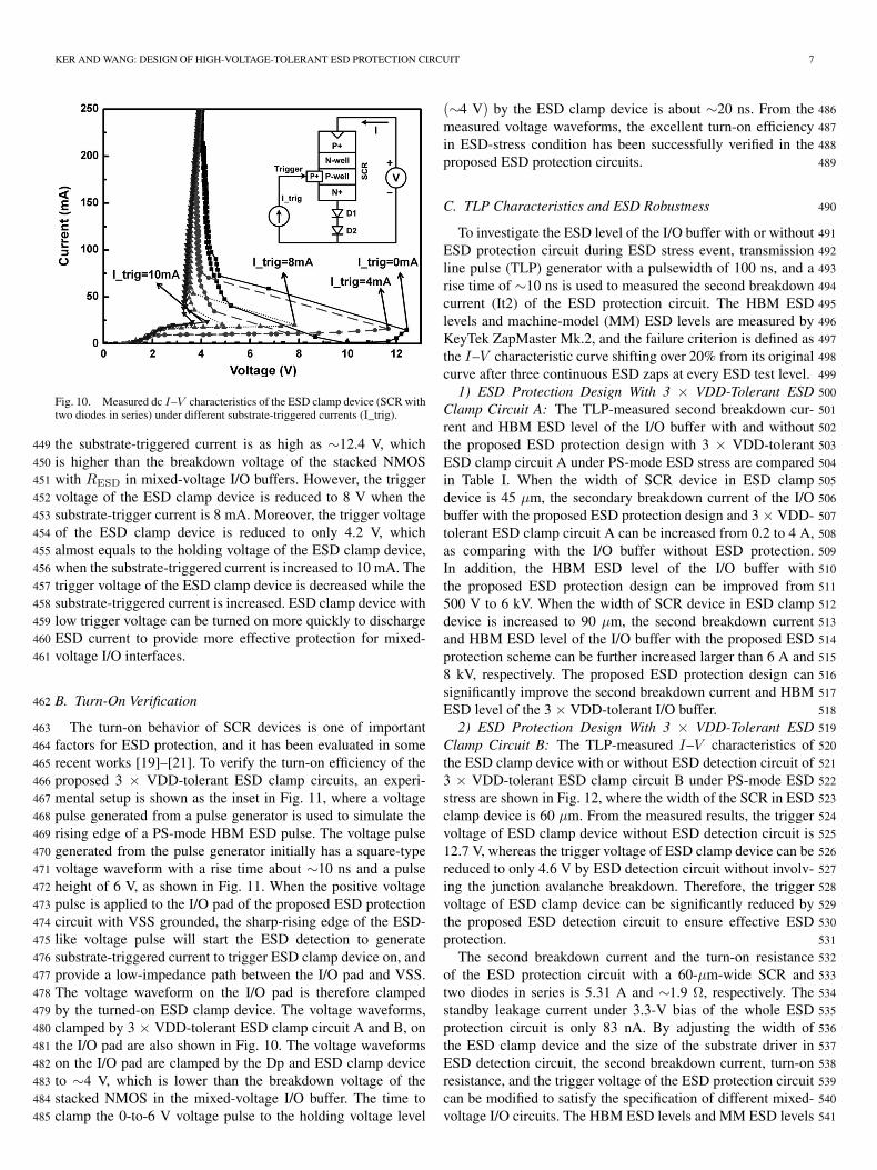
Fig. 10. Measured dc I–V characteristics of the ESD clamp device (SCR withtwo diodes in series) under different substrate-triggered currents (I_trig).
the substrate-triggered current is as high as ∼12.4 V, which449
is higher than the breakdown voltage of the stacked NMOS450
with RESD in mixed-voltage I/O buffers. However, the trigger451
voltage of the ESD clamp device is reduced to 8 V when the452
substrate-trigger current is 8 mA. Moreover, the trigger voltage453
of the ESD clamp device is reduced to only 4.2 V, which454
almost equals to the holding voltage of the ESD clamp device,455
when the substrate-triggered current is increased to 10 mA. The456
trigger voltage of the ESD clamp device is decreased while the457
substrate-triggered current is increased. ESD clamp device with458
low trigger voltage can be turned on more quickly to discharge459
ESD current to provide more effective protection for mixed-460
voltage I/O interfaces.461
B. Turn-On Verification462
The turn-on behavior of SCR devices is one of important463
factors for ESD protection, and it has been evaluated in some464
recent works [19]–[21]. To verify the turn-on efficiency of the465
proposed 3 × VDD-tolerant ESD clamp circuits, an experi-466
mental setup is shown as the inset in Fig. 11, where a voltage467
pulse generated from a pulse generator is used to simulate the468
rising edge of a PS-mode HBM ESD pulse. The voltage pulse469
generated from the pulse generator initially has a square-type470
voltage waveform with a rise time about ∼10 ns and a pulse471
height of 6 V, as shown in Fig. 11. When the positive voltage472
pulse is applied to the I/O pad of the proposed ESD protection473
circuit with VSS grounded, the sharp-rising edge of the ESD-474
like voltage pulse will start the ESD detection to generate475
substrate-triggered current to trigger ESD clamp device on, and476
provide a low-impedance path between the I/O pad and VSS.477
The voltage waveform on the I/O pad is therefore clamped478
by the turned-on ESD clamp device. The voltage waveforms,479
clamped by 3 × VDD-tolerant ESD clamp circuit A and B, on480
the I/O pad are also shown in Fig. 10. The voltage waveforms481
on the I/O pad are clamped by the Dp and ESD clamp device482
to ∼4 V, which is lower than the breakdown voltage of the483
stacked NMOS in the mixed-voltage I/O buffer. The time to484
clamp the 0-to-6 V voltage pulse to the holding voltage level485
(∼4 V) by the ESD clamp device is about ∼20 ns. From the 486
measured voltage waveforms, the excellent turn-on efficiency 487
in ESD-stress condition has been successfully verified in the 488
proposed ESD protection circuits. 489
C. TLP Characteristics and ESD Robustness 490
To investigate the ESD level of the I/O buffer with or without 491
ESD protection circuit during ESD stress event, transmission 492
line pulse (TLP) generator with a pulsewidth of 100 ns, and a 493
rise time of ∼10 ns is used to measured the second breakdown 494
current (It2) of the ESD protection circuit. The HBM ESD 495
levels and machine-model (MM) ESD levels are measured by 496
KeyTek ZapMaster Mk.2, and the failure criterion is defined as 497
the I–V characteristic curve shifting over 20% from its original 498
curve after three continuous ESD zaps at every ESD test level. 499
1) ESD Protection Design With 3 × VDD-Tolerant ESD 500
Clamp Circuit A: The TLP-measured second breakdown cur- 501
rent and HBM ESD level of the I/O buffer with and without 502
the proposed ESD protection design with 3 × VDD-tolerant 503
ESD clamp circuit A under PS-mode ESD stress are compared 504
in Table I. When the width of SCR device in ESD clamp 505
device is 45 µm, the secondary breakdown current of the I/O 506
buffer with the proposed ESD protection design and 3 × VDD- 507
tolerant ESD clamp circuit A can be increased from 0.2 to 4 A, 508
as comparing with the I/O buffer without ESD protection. 509
In addition, the HBM ESD level of the I/O buffer with 510
the proposed ESD protection design can be improved from 511
500 V to 6 kV. When the width of SCR device in ESD clamp 512
device is increased to 90 µm, the second breakdown current 513
and HBM ESD level of the I/O buffer with the proposed ESD 514
protection scheme can be further increased larger than 6 A and 515
8 kV, respectively. The proposed ESD protection design can 516
significantly improve the second breakdown current and HBM 517
ESD level of the 3 × VDD-tolerant I/O buffer. 518
2) ESD Protection Design With 3 × VDD-Tolerant ESD 519
Clamp Circuit B: The TLP-measured I–V characteristics of 520
the ESD clamp device with or without ESD detection circuit of 521
3 × VDD-tolerant ESD clamp circuit B under PS-mode ESD 522
stress are shown in Fig. 12, where the width of the SCR in ESD 523
clamp device is 60 µm. From the measured results, the trigger 524
voltage of ESD clamp device without ESD detection circuit is 525
12.7 V, whereas the trigger voltage of ESD clamp device can be 526
reduced to only 4.6 V by ESD detection circuit without involv- 527
ing the junction avalanche breakdown. Therefore, the trigger 528
voltage of ESD clamp device can be significantly reduced by 529
the proposed ESD detection circuit to ensure effective ESD 530
protection. 531
The second breakdown current and the turn-on resistance 532
of the ESD protection circuit with a 60-µm-wide SCR and 533
two diodes in series is 5.31 A and ∼1.9 Ω, respectively. The 534
standby leakage current under 3.3-V bias of the whole ESD 535
protection circuit is only 83 nA. By adjusting the width of 536
the ESD clamp device and the size of the substrate driver in 537
ESD detection circuit, the second breakdown current, turn-on 538
resistance, and the trigger voltage of the ESD protection circuit 539
can be modified to satisfy the specification of different mixed- 540
voltage I/O circuits. The HBM ESD levels and MM ESD levels 541

8 IEEE TRANSACTIONS ON DEVICE AND MATERIALS RELIABILITY, VOL. 9, NO. 1, MARCH 2009
Fig. 11. Measured voltage waveforms, clamped by 3 × VDD-tolerant ESD clamp circuit A and B, on the I/O pad when a 0-to-6 V voltage pulse is applying toI/O pad under the PS-mode ESD stress (VDD floating and VSS grounded).
TABLE IESD ROBUSTNESS OF I/O BUFFER WITH OR WITHOUT ESD PROTECTION
CIRCUIT WITH ESD CLAMP CIRCUIT A
Fig. 12. Measured TLP I–V characteristics of the ESD clamp device in the3 × VDD-tolerant ESD clamp circuit B with or without ESD detection circuitunder PS-mode ESD stress.
of the proposed ESD protection circuit with 3 × VDD-tolerant542
ESD clamp circuit B with various widths of SCR-based ESD543
clamp devices under PS-mode ESD stress are listed in Table II.544
TABLE IIESD ROBUSTNESS OF THE PROPOSED ESD PROTECTION CIRCUIT WITH
ESD CLAMP CIRCUIT B WITH VARIOUS WIDTHS OF ESD CLAMP DEVICES
The HBM ESD levels of ESD protection circuit under ESD 545
clamp device width of 30, 45, and 60 µm are 4 kV, 6.2 kV, 546
and larger than 8 kV, respectively. Besides, the MM ESD levels 547
of ESD protection circuit under ESD clamp device width of 548
30, 45, and 60 µm are 260, 380, and 440 V, respectively. The 549
corresponding second breakdown current measured by TLP is 550
also listed in Table II. 551
The CDM ESD robustness of the proposed ESD protection 552
circuits are also verified by KeyTek RCDM tester. The 3 × 553
VDD-tolerant I/O buffer protected by the proposed ESD protec- 554
tion circuits in this paper (both 3 × VDD-tolerant ESD clamp 555
circuits A and B) can achieve a CDM ESD level of greater than 556
±1 kV. 557
V. PIN-TO-PIN ESD PROTECTION 558
In the whole chip ESD protection design, the proposed 3 × 559
VDD-tolerant ESD protection circuit can be shared with other 560
3 × VDD-tolerant I/O buffers by connecting ESD bus to each 561
other to achieve pin-to-pin ESD protection, as shown in Fig. 13. 562
During the pin-to-pin ESD test, the ESD stress is applied to 563
one I/O pad with other I/O pad grounded, where the VDD 564
and VSS are initially floating. The ESD current will flow from 565
one I/O pad through the forward diode Dp, ESD bus line, 566
and then through the proposed 3 × VDD-tolerant ESD clamp 567
circuit to the VSS line, finally from the VSS line through the 568

KER AND WANG: DESIGN OF HIGH-VOLTAGE-TOLERANT ESD PROTECTION CIRCUIT 9
Fig. 13. Shared ESD bus and 3 × VDD-tolerant ESD clamp circuit for whole set of I/O buffers to achieve pin-to-pin ESD protection.
forward diode Dn to the other grounded I/O pad. Therefore, the569
pin-to-pin ESD protection can be achieved by using this ESD570
protection scheme with the proposed 3 × VDD-tolerant ESD571
clamp circuit for 3 × VDD-tolerant mixed-voltage I/O buffers.572
VI. CONCLUSION573
Two novel circuit solutions on ESD protection design, re-574
alized with 1 × VDD devices for mixed-voltage I/O buffer575
with 3 × VDD input tolerance, have been successfully verified576
in two different 0.13-µm 1.2-V CMOS process. The four-577
mode (PS, NS, PD, and ND) ESD stresses and pin-to-pin578
ESD stresses on the 1.2/3.3-V mixed-voltage I/O buffer can579
be effectively discharged by the ESD protection scheme, with580
the proposed 3 × VDD-tolerant power-rail ESD clamp circuits.581
The proposed 3 × VDD-tolerant power-rail ESD clamp circuits582
operates without gate-oxide reliability issue under the normal583
circuit operating conditions. By using the special control circuit584
in the 3 × VDD-tolerant ESD clamp circuit B, the device585
sizes of the resistor, capacitor, and the substrate driver can be586
reduced. Therefore, the active area and the standby leakage587
current of the ESD detection circuit in 3 × VDD-tolerant ESD588
clamp circuit B can be further reduced. In addition, the ESD589
detection circuit has also shown significant help on reducing590
the trigger voltage of ESD clamp device. The turn-on behaviors591
of the ESD clamp device have been measured to verify the592
effectiveness of the ESD detection circuit for both two 3 ×593
VDD-tolerant ESD clamp circuits. The experimental results594
have also confirmed that the ESD robustness of the 3 × VDD595
mixed-voltage I/O buffer can be significantly increased up to596
8 kV with the proposed ESD protection designs. These two597
proposed power-rail ESD clamp circuit with the advantages of598
low leakage current, high ESD robustness, and no gate-oxide599
reliability issue are the excellent ESD protection solutions to600
the mixed-voltage I/O interfaces with high-voltage input/output 601
signals. 602
REFERENCES 603
[1] M.-D. Ker, S.-L. Chen, and C.-S. Tsai, “Overview and design of mixed- 604voltage I/O buffers with low-voltage thin-oxide CMOS transistors,” IEEE 605Trans. Circuits Syst. I, Reg. Papers, vol. 53, no. 9, pp. 1934–1945, 606Sep. 2006. 607
[2] Y. Luo, D. Nayak, D. Gitlin, M.-Y. Hao, C.-H. Kao, and C.-H. Wang, “Ox- 608ide reliability of drain engineered I/O NMOS from hot carrier injection,” 609IEEE Electron Device Lett., vol. 24, no. 11, pp. 686–688, Nov. 2003. 610
[3] B. Serneels, T. Piessens, M. Steyaert, and W. Dehaene, “A high-voltage 611output driver in a standard 2.5 V 0.25µm CMOS technology,” in Proc. 612IEEE Int. Solid-State Circuit Conf. Dig. Tech. Papers, 2004, pp. 146–147. 613
[4] W. R. Anderson and B. Krakauer, “ESD protection for mixed-voltage 614I/O using NMOS transistors stacked in a cascode configuration,” in Proc. 615EOS/ESD Symp., 1998, pp. 54–62. 616
[5] J. Miller, M. Khazhinsky, and J. Weldon, “Engineering the cascoded 617NMOS output buffer for maximum Vt1,” in Proc. EOS/ESD Symp., 2000, 618pp. 308–317. 619
[6] M.-D. Ker and K.-H. Lin, “Overview on electrostatic discharge protection 620designs for mixed-voltage I/O interfaces: Design concept and circuit im- 621plementations,” IEEE Trans. Circuits Syst. I, Reg. Papers, vol. 53, no. 2, 622pp. 235–246, Feb. 2006. 623
[7] M.-D. Ker and S.-L. Chen, “Mixed-voltage I/O buffer with dynamic gate- 624bias circuit to achieve 3× VDD input tolerance by using 1× VDD devices 625and single VDD supply,” in Proc. IEEE Int. Solid-State Circuits Conf. Dig. 626Tech. Papers, 2005, pp. 524–525. 627
[8] T. Maloney and W. Kan, “Stacked PMOS clamps for high voltage power 628supply protection,” in Proc. EOS/ESD Symp., 1999, pp. 70–77. 629
[9] S. S. Poon and T. Maloney, “New considerations for MOSFET power 630clamps,” in Proc. EOS/ESD Symp., 2002, pp. 1–5. 631
[10] M.-D. Ker, W.-Y. Chen, and K.-C. Hsu, “Design on power-rail ESD 632clamp circuit for 3.3-V I/O interface by using only 1-V/2.5-V low-voltage 633devices in a 130-nm CMOS process,” in Proc. IEEE Int. Rel. Phys. Symp., 6342005, pp. 606–607. 635
[11] M.-D. Ker, W.-J. Chang, C.-T. Wang, and W.-Y. Chen, “ESD protection 636for mixed-voltage I/O in low-voltage thin-oxide CMOS,” in Proc. IEEE 637Int. Solid-State Circuits Conf. Dig. Tech. Papers, 2006, pp. 546–547. 638
[12] M.-D. Ker and C.-T. Wang, “ESD protection design by using only 1 × 639VDD low-voltage devices for mixed-voltage I/O buffers with 3 × VDD 640input tolerance,” in Proc. IEEE Asian Solid-State Circuits Conf., 2006, 641pp. 287–290. 642

10 IEEE TRANSACTIONS ON DEVICE AND MATERIALS RELIABILITY, VOL. 9, NO. 1, MARCH 2009
[13] M.-D. Ker, C.-T. Wang, T.-H. Tang, and K.-C. Su, “Design of high-643voltage-tolerant power-rail ESD clamp circuit in low-voltage CMOS644processes,” in Proc. IEEE Int. Rel. Phys. Symp., 2007, pp. 594–595.645
[14] L. R. Avery, “ESD protection for overvoltage friendly input/output cir-646cuits,” U.S. Patent 5 708 550, Jan. 13, 1998.647
[15] M.-D. Ker, “Whole-chip ESD protection design with efficient VDD-to-648VSS ESD clamp circuit for submicron CMOS VLSI,” IEEE Trans. Elec-649tron Devices, vol. 46, no. 1, pp. 173–183, Jan. 1999.650
[16] M.-D. Ker and K.-C. Hsu, “Overview of on-chip electrostatic discharge651protection design with SCR-based devices in CMOS integrated circuits,”652IEEE Trans. Device Mater. Rel., vol. 5, no. 2, pp. 235–249, Jun. 2005.653
[17] M.-D. Ker and K.-C. Hsu, “Latchup-free ESD protection design with654complementary substrate-triggered SCR devices,” IEEE J. Solid-State655Circuits, vol. 38, no. 8, pp. 1380–1392, Aug. 2003.656
[18] M.-D. Ker and C.-H. Chuang, “Electrostatic discharge protection de-657sign for mixed-voltage CMOS I/O buffers,” IEEE J. Solid-State Circuits,658vol. 37, no. 8, pp. 1046–1055, Aug. 2002.659
[19] M.-D. Ker and K.-C. Hsu, “SCR device fabricated with dummy-gate660structure to improve turn-on speed for effective ESD protection in CMOS661technology,” IEEE Trans. Semicond. Manuf., vol. 18, no. 2, pp. 320–327,662May 2005.663
[20] J. D. Sarro, K. Chatty, R. Gauthier, and E. Rosenbaum, “Evaluation of664SCR-based ESD protection devices in 90 nm and 65 nm CMOS technolo-665gies,” in Proc. IEEE Int. Rel. Phys. Symp., 2007, pp. 348–357.666
[21] G. Wybo, S. Verleye, B. V. Camp, and O. Marchial, “Characterizing667the transient device behavior of SCRs by means of VFTLP waveform668analysis,” in Proc. EOS/ESD Symp., 2007, pp. 366–375.669
Ming-Dou Ker (S’92–M’94–SM’97–F’08) received670the Ph.D. degree from the Institute of Electronics,671National Chiao-Tung University (NCTU), Hsinchu,672Taiwan, in 1993.673
He was the Department Manager with the VLSI674Design Division, Computer and Communication Re-675search Laboratories, Industrial Technology Research676Institute, Hsinchu. Since 2004, he has been a Full677Professor with the Department of Electronics En-678gineering, NCTU. From 2006 to 2008, he served679as the Director of Master Degree Program with the680
College of Electrical Engineering and Computer Science, NCTU, as well as the681Associate Executive Director of the National Science and Technology Program682on System-on-Chip (NSoC Office), Taiwan. In 2008, he was rotated to serve683as the Chair Professor and the Vice President of I-Shou University, Kaohsiung,684Taiwan. He has proposed many inventions to improve the reliability and quality685of integrated circuits, which have been granted with 136 U.S. patents and 143686(Taiwan) patents. He had been invited to teach and/or to consult the reliability687and quality design for integrated circuits by hundreds of design houses and688semiconductor companies in the worldwide IC industry. In the field of relia-689bility and quality design for circuits and systems in CMOS technology, he has690published over 350 technical papers in international journals and conferences.691His current research interests include reliability and quality design for nano-692electronics and gigascale systems, high-speed and mixed-voltage I/O interface693circuits, on-glass circuits for system-on-panel applications, and biomimetic694circuits and systems for intelligent prosthesis.695
Dr. Ker has served as a member of the Technical Program Committee and696the Session Chair of numerous international conferences. He served as the697Associate Editor for the IEEE TRANSACTIONS ON VLSI SYSTEMS. He has698been selected as the Distinguished Lecturer in the IEEE Circuits and Systems699Society (for year 2006–2007) and in the IEEE Electron Devices Society (since7002008). He was the President of Foundation in the Taiwan ESD Association. In7012005, one of his patents on ESD protection design has been awarded with the702National Invention Award in Taiwan. In 2008, he has been elevated as an IEEE703Fellow “for his contributions to the electrostatic protection in integrated circuits704and the performance optimization of VLSI microsystems.”705
Chang-Tzu Wang (S’06) was born in Taiwan 706in 1983. He received the B.S. degree from the 707Department of Electronics Engineering, National 708Chiao-Tung University, Hsinchu, Taiwan, in 2005, 709where he is currently working toward the Ph.D. 710degree in the Institute of Electronics. 711
In 2006, he was with the ESD Engineering Depart- 712ment, Reliability Technology and Assurance Divi- 713sion, United Microelectronic Corporation, Hsinchu, 714as a Senior Engineer. His current research interests 715include on-chip ESD protection circuit design for 716
mixed-voltage I/O circuits and low-power applications. 717