Protective Control for Robot Manipulator by Sliding Mode ...
Upload
waqas-tariqCategory
view
213download
1
Farzin Piltan, N. Sulaiman, M. H. Marhaban, Adel Nowzary & Mostafa Tohidian
International Journal of Robotics and Automation, (IJRA), Volume (2): Issue (3) : 2011 173
Design of FPGA-based Sliding Mode Controller for Robot Manipulator
Farzin Piltan [email protected] Department of Electrical and Electronic Engineering, Faculty of Engineering, Universiti Putra Malaysia 43400 Serdang, Selangor, Malaysia
N. Sulaiman [email protected] Department of Electrical and Electronic Engineering, Faculty of Engineering, Universiti Putra Malaysia 43400 Serdang, Selangor, Malaysia
M. H. Marhaban [email protected] Department of Electrical and Electronic Engineering, Faculty of Engineering, Universiti Putra Malaysia 43400 Serdang, Selangor, Malaysia
Adel Nowzary [email protected] Industrial Electrical and Electronic Engineering SanatkadeheSabze Pasargad. CO (S.S.P. Co), NO:16 , PO.Code 71347-66773, Fourth floor Dena Apr , Seven Tir Ave , Shiraz , Iran
Mostafa Tohidian [email protected] Industrial Electrical and Electronic Engineering SanatkadeheSabze Pasargad. CO (S.S.P. Co), NO:16 , PO.Code 71347-66773, Fourth floor Dena Apr , Seven Tir Ave , Shiraz , Iran
Abstract
One of the most active research areas in the field of robotics is robot manipulators control, because these systems are multi-input multi-output (MIMO), nonlinear, and uncertainty. At present, robot manipulators is used in unknown and unstructured situation and caused to provide complicated systems, consequently strong mathematical tools are used in new control methodologies to design nonlinear robust controller with satisfactory performance (e.g., minimum error, good trajectory, disturbance rejection). Robotic systems controlling is vital due to the wide range of application. Obviously stability and robustness are the most minimum requirements in control systems; even though the proof of stability and robustness is more important especially in the case of nonlinear systems. One of the best nonlinear robust controllers which can be used in uncertainty nonlinear systems is sliding mode controller (SMC). Chattering phenomenon is the most important challenge in this controller. Most of nonlinear controllers need real time mobility operation; one of the most important devices which can be used to solve this challenge is Field Programmable Gate Array (FPGA). FPGA can be used to design a controller in a single chip Integrated Circuit (IC). In this research the SMC is designed using VHDL language for implementation on FPGA device (XA3S1600E-Spartan-3E), with minimum chattering and high processing speed (63.29 MHz).
Keywords: Robot Manipulator, Sliding Mode Controller, Chattering Phenomenon, FPGA, VHDL language.
Farzin Piltan, N. Sulaiman, M. H. Marhaban, Adel Nowzary & Mostafa Tohidian
International Journal of Robotics and Automation, (IJRA), Volume (2): Issue (3) : 2011 174
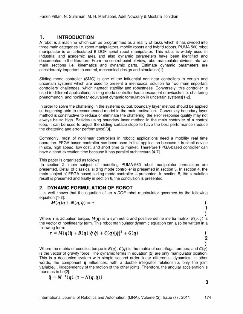
1. INTRODUCTION A robot is a machine which can be programmed as a reality of tasks which it has divided into three main categories i.e. robot manipulators, mobile robots and hybrid robots. PUMA 560 robot manipulator is an articulated 6 DOF serial robot manipulator. This robot is widely used in industrial and academic area and also dynamic parameters have been identified and documented in the literature. From the control point of view, robot manipulator divides into two main sections i.e. kinematics and dynamic parts. Estimate dynamic parameters are considerably important to control, mechanical design and simulation[1]. Sliding mode controller (SMC) is one of the influential nonlinear controllers in certain and uncertain systems which are used to present a methodical solution for two main important controllers’ challenges, which named: stability and robustness. Conversely, this controller is used in different applications; sliding mode controller has subsequent drawbacks i.e. chattering phenomenon, and nonlinear equivalent dynamic formulation in uncertain systems[1-2].
In order to solve the chattering in the systems output, boundary layer method should be applied so beginning able to recommended model in the main motivation. Conversely boundary layer method is constructive to reduce or eliminate the chattering; the error response quality may not always be so high. Besides using boundary layer method in the main controller of a control loop, it can be used to adjust the sliding surface slope to have the best performance (reduce the chattering and error performance)[3].
Commonly, most of nonlinear controllers in robotic applications need a mobility real time operation. FPGA-based controller has been used in this application because it is small device in size, high speed, low cost, and short time to market. Therefore FPGA-based controller can have a short execution time because it has parallel architecture [4-7].
This paper is organized as follows: In section 2, main subject of modelling PUMA-560 robot manipulator formulation are presented. Detail of classical sliding mode controller is presented in section 3. In section 4, the main subject of FPGA-based sliding mode controller is presented. In section 5, the simulation result is presented and finally in section 6, the conclusion is presented.
2. DYNAMIC FORMULATION OF ROBOT It is well known that the equation of an n-DOF robot manipulator governed by the following equation [1-2]: ������ � ���, � � � (
1)
Where τ is actuation torque, ���� is a symmetric and positive define inertia matrix, �� , � is the vector of nonlinearity term. This robot manipulator dynamic equation can also be written in a following form: � ������ � ������ � � � ������ �� � ���� (
2)
Where the matrix of coriolios torque is ����, ���� is the matrix of centrifugal torques, and ���� is the vector of gravity force. The dynamic terms in equation (2) are only manipulator position. This is a decoupled system with simple second order linear differential dynamics. In other words, the component �� influences, with a double integrator relationship, only the joint variable �, independently of the motion of the other joints. Therefore, the angular acceleration is found as to be[2]: �� ������. �� � ���, � ��
3
Farzin Piltan, N. Sulaiman, M. H. Marhaban, Adel Nowzary & Mostafa Tohidian
International Journal of Robotics and Automation, (IJRA), Volume (2): Issue (3) : 2011 175
) This technique is very attractive from a control point of view. This paper is focused on the design FPGA-based controller for PUMA-560 robot manipulator.
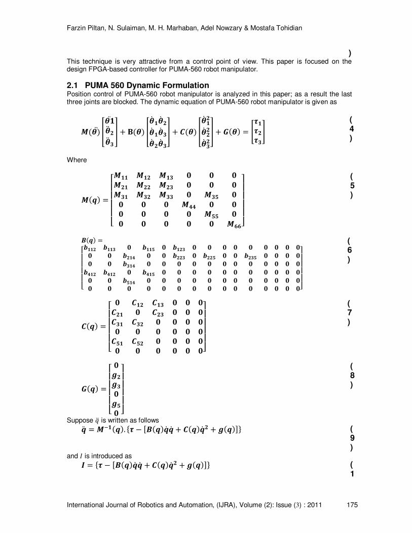
2.1 PUMA 560 Dynamic Formulation Position control of PUMA-560 robot manipulator is analyzed in this paper; as a result the last three joints are blocked. The dynamic equation of PUMA-560 robot manipulator is given as
����� ����� ��� �� � � ��� �� �� �� �� �� �� �� � ���� �� ��� ��� ��� � ���� !������" (
4)
Where
���� #$$$$%��� ��� ��� & & &��� ��� ��� & & &��� ��� ��� & ��' && & & �(( & && & & & �'' && & & & & �))*+
+++,
(5)
����
#$$$$%-��� -��� & -��' & -��� & & & & & & & & && & -��( & & -��� & -��' & & -��' & & & && & -��( & & & & & & & & & & & &-(�� -(�� & -(�' & & & & & & & & & & && & -'�( & & & & & & & & & & & && & & & & & & & & & & & & & &*+
+++,
(6)
���� #$$$$% & ��� ��� & & &��� & ��� & & &��� ��� & & & && & & & & &�'� �'� & & & && & & & & &*+
+++,
(7)
���� #$$$$% &.�.�&.'& *+
+++,
(8)
Suppose � is written as follows �� ������. �� � ������ � � ����� � � .����� (9)
and / is introduced as 0 �� � ������ � � ����� � � .����� (1
Farzin Piltan, N. Sulaiman, M. H. Marhaban, Adel Nowzary & Mostafa Tohidian
International Journal of Robotics and Automation, (IJRA), Volume (2): Issue (3) : 2011 176
0) � can be written as �� ������. 0 (11)
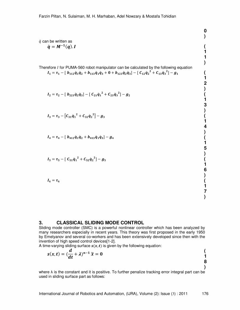
Therefore / for PUMA-560 robot manipulator can be calculated by the following equation 0� �� � � -���� �� � � -���� �� � � & � -���� �� �� � � ���� �� � ���� ��� � .� (12) 0� �� � � -���� �� �� � � ���� �� � ���� ��� � .� (13) 0� �� � 1���� �� � ���� ��2 � .� (14) 0( �( � � -(��� �� � � -(��� �� �� � .( (15) 0' �' � � �'�� �� � �'�� ��� � .' (16) 0) �) (17)
3. CLASSICAL SLIDING MODE CONTROL Sliding mode controller (SMC) is a powerful nonlinear controller which has been analyzed by many researchers especially in recent years. This theory was first proposed in the early 1950 by Emelyanov and several co-workers and has been extensively developed since then with the invention of high speed control devices[1-2]. A time-varying sliding surface 3�4, 5� is given by the following equation: 3�4, 5� � 665 � 7�8�� 49 &
(18)
where λ is the constant and it is positive. To further penalize tracking error integral part can be used in sliding surface part as follows:
Farzin Piltan, N. Sulaiman, M. H. Marhaban, Adel Nowzary & Mostafa Tohidian
International Journal of Robotics and Automation, (IJRA), Volume (2): Issue (3) : 2011 177
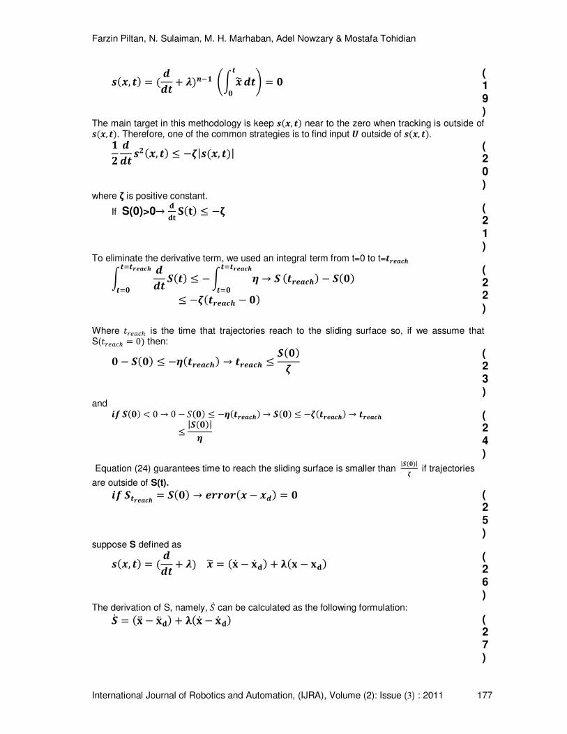
3�4, 5� � 665 � 7�8�� :; 495& 65< &
(19)
The main target in this methodology is keep 3�4, 5� near to the zero when tracking is outside of 3�4, 5�. Therefore, one of the common strategies is to find input = outside of 3�4, 5�. �� 665 3��4, 5� > �?|3�4, 5�| (20)
where ζ is positive constant.
If S(0)>0A BBC D�C� > �E (21)
To eliminate the derivative term, we used an integral term from t=0 to t=5FGHIJ ; 6655K5FGHIJ5K& L�5� > � ; M A L5K5FGHIJ
5K& �5FGHIJ� � L�&�> �?�5FGHIJ � &�
(22)
Where NOPQRS is the time that trajectories reach to the sliding surface so, if we assume that S(NOPQRS 0� then: & � L�&� > �M�5FGHIJ� A 5FGHIJ > L�&�?
(23)
and UV L�&� W 0 A 0 � X�&� > �M�5FGHIJ� A L�&� > �?�5FGHIJ� A 5FGHIJ> |L�&�|M
(24)
Equation (24) guarantees time to reach the sliding surface is smaller than |L�&�|? if trajectories
are outside of S(t). UV L5FGHIJ L�&� A GFFYF�4 � 46� & (25)
suppose S defined as 3�4, 5� � 665 � 7� 49 �Z � Z B� � [�Z � ZB� (26)
The derivation of S, namely, X can be calculated as the following formulation: L �Z� � Z� B� � [�Z � Z B� (27)
Farzin Piltan, N. Sulaiman, M. H. Marhaban, Adel Nowzary & Mostafa Tohidian
International Journal of Robotics and Automation, (IJRA), Volume (2): Issue (3) : 2011 178
suppose define the second order system as, 4� V � \ A L V � = � 4� 6 � [�Z � Z B� (28)
Where f is the dynamic uncertain, and also if X 0 ]^_ X 0, to have the best approximation
,=̀ defined by, =̀ �Va � 4� 6 � 7�Z � Z B� (29)
A simple solution to get the sliding condition when the dynamic parameters have uncertainty is the switching control law: =6U3 =̀ � b�4ccd, 5�. 3.8�3� (
30)
Where the function of 3.8�L� defined as;
3.8�3� e � 3 f 0�� 3 W 0& 3 &g (31)
and the b�4ccd, 5� is the positive constant. Suppose to rewrite the equation (20) by the following equation, �� 665 3��4, 5� D . D 1V � Va � b3.8�3�2. L hV � Vai. L � b|L|
(32)
Another method is using equation (23) instead of (24) to get sliding surface 3�4, 5� � 665 � 7�� :; 495& 65<
�Z � Z B� � �7�Z � Z B� � [��Z � ZB�
(33)
in this method the approximation of = can be calculated as =̀ �Va � 4� 6 � �7�Z � Z B� � [��Z � ZB� (34)
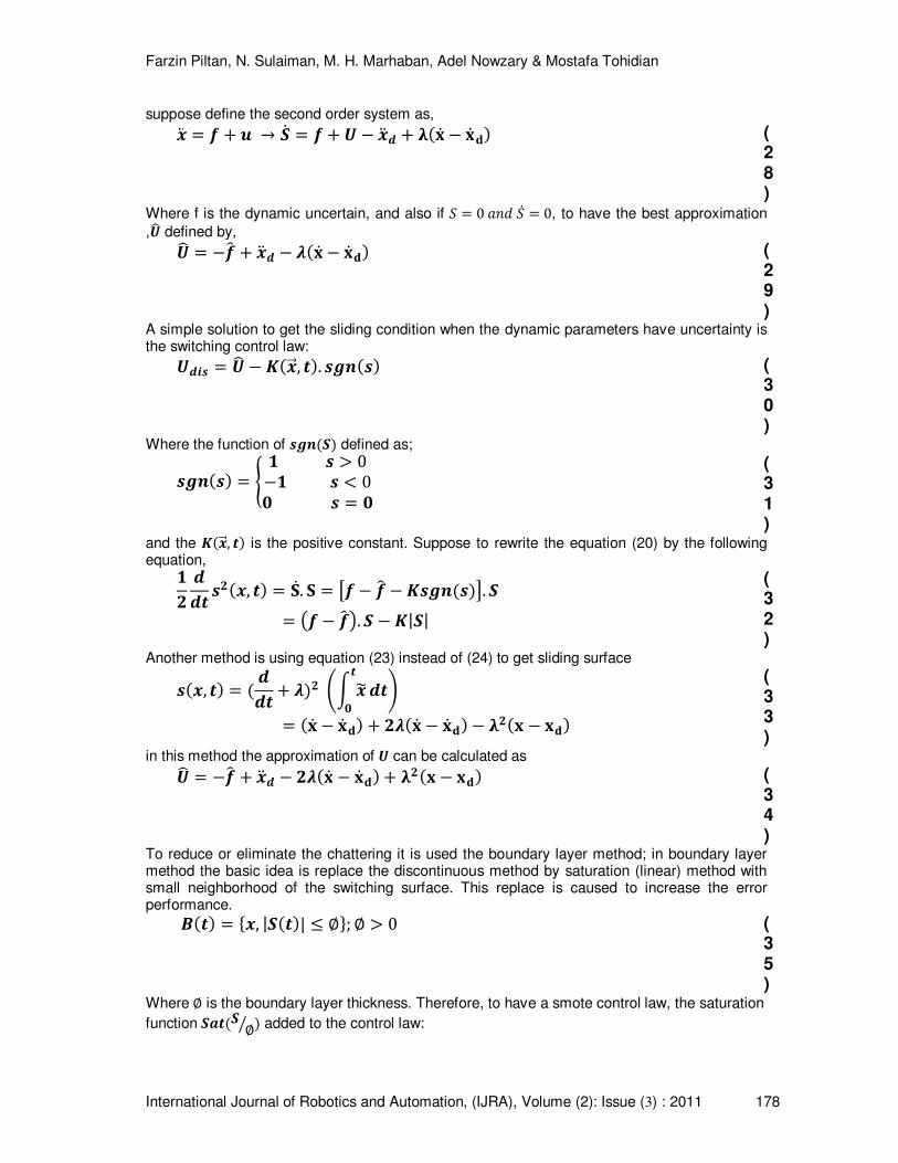
To reduce or eliminate the chattering it is used the boundary layer method; in boundary layer method the basic idea is replace the discontinuous method by saturation (linear) method with small neighborhood of the switching surface. This replace is caused to increase the error performance.
��5� �4, |L�5�| > j�; j f 0 (35)
Where j is the boundary layer thickness. Therefore, to have a smote control law, the saturation
function LH5�L jl � added to the control law:
Farzin Piltan, N. Sulaiman, M. H. Marhaban, Adel Nowzary & Mostafa Tohidian
International Journal of Robotics and Automation, (IJRA), Volume (2): Issue (3) : 2011 179
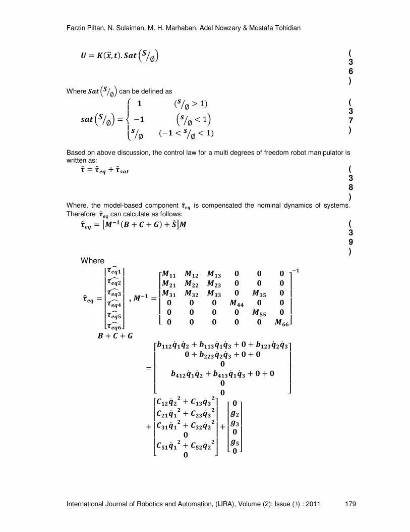
= b�4ccd, 5�. LH5 mL jl n (36)
Where LH5 mL jl n can be defined as
3H5 mL jl n opqpr � �3 jl f 1�
�� m3 jl W 1n3 jl ��� W 3 jl W 1�g
(37)
Based on above discussion, the control law for a multi degrees of freedom robot manipulator is written as: �t �tG� � �t3H5 (
38)
Where, the model-based component �tG� is compensated the nominal dynamics of systems.
Therefore �tG� can calculate as follows: �tG� 1����� � � � �� � L 2� (39)
Where
�tG� #$$$$$%�G��u�G��u�G��u�G�(u�G�'u�G�)u *+
++++, , ���
#$$$$%��� ��� ��� & & &��� ��� ��� & & &��� ��� ��� & ��' && & & �(( & && & & & �'' && & & & & �))*+
+++,
��
� � � � �
#$$$$%-���� �� � � -���� �� � � & � -���� �� �& � -���� �� � � & � &&-(��� �� � � -(��� �� � � & � &&& *+
+++,
�#$$$$$%���� �� � ���� ������ �� � ���� ������ �� � ���� ��&�'�� �� � �'�� ��& *+
++++,
�#$$$$% &.�.�&.'& *+
+++,
Farzin Piltan, N. Sulaiman, M. H. Marhaban, Adel Nowzary & Mostafa Tohidian
International Journal of Robotics and Automation, (IJRA), Volume (2): Issue (3) : 2011 180
L #$$$$$%L �L �L �L (L 'L )*+
++++, and �
#$$$$%��� ��� ��� & & &��� ��� ��� & & &��� ��� ��� & ��' && & & �(( & && & & & �'' && & & & & �))*+
+++,
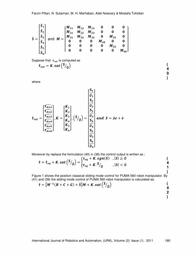
Suppose that �3H5 is computed as �t3H5 b. 3H5 mL jl n (
40)
where
�t3H5 #$$$$%�6v3�w�6v3�w�6v3�w�6v3(w�6v3'w�6v3)w *+
+++, , b
#$$$$%b�b�b�b(b'b)*+
+++, , mL jl n
#$$$$$$$$$$$$%D�j�D�j�D�j�D(j(D'j'D)j)*+
+++++++++++,
H86 L 7G � G
Moreover by replace the formulation (40) in (38) the control output is written as ;
�t �tG� � b. 3H5 mL jl n e�G� � b. 3.8�L� , |L| x j�G� � b. L jl , |L| W jg (41)
Figure 1 shows the position classical sliding mode control for PUMA-560 robot manipulator. By (41) and (39) the sliding mode control of PUMA 560 robot manipulator is calculated as; �t 1����� � � � �� � L 2� � b. 3H5 mL jl n (
42)
Farzin Piltan, N. Sulaiman, M. H. Marhaban, Adel Nowzary & Mostafa Tohidian
International Journal of Robotics and Automation, (IJRA), Volume (2): Issue (3) : 2011 181
4. FPGA-BASED SLIDING MODE CONTROLLER Research on FPGA-based control of systems is considerably growing as their applications such as industrial automation, robotic surgery, and space station's robot arm demand more accuracy, reliability, high performance. For instance, the FPGA-based controls of robot manipulator have been reported in [5-6, 8-13]. Shao and Sun [8, 10]have proposed an adaptive control algorithm based on FPGA for control of SCARA robot manipulator. They are designed this controller into two micro base controller, the linear part controller is implemented in the FPGA and the nonlinear estimation controller is implemented in DSP. Moreover this controller is implemented in a Xilinx-FPGA XC3S400 with the 20 KHz position loop frequency. The FPGA based servo control and inverse kinematics for Mitsubishi RV-M1 micro robot is presented in[9, 11-12] which to reduce the limitation of FPGA capacitance they are used 42 steps finite state machine (FSM) in 840 n second. Meshram and Harkare [5-6] have presented a multipurpose FPGA-based 5 DOF robot manipulator using VHDL coding in Xilinx ISE 11.1. This controller has two most important advantages: easy to implement and flexible. Zeyad Assi Obaid et al. [13] have proposed a digital PID fuzzy logic controller using FPGA for tracking tasks that yields semi-global stability of all closed-loop signals.
The basic information about FPGA has been reported in [4-5, 12-15]. A review of design and implementation of FPGA-based systems has been presented in [4]. The FPGA-based sliding mode control of systems has been reported in [7, 16-18]. Lin et al. [7] have presented low cost and high performance FPGA-based fuzzy sliding mode controller for linear induction motor with
80% of flip flops. The fuzzy inference system has 2 inputs �X & X� and one output z{ with nine
rules. Ramos et al. [16] have reported FPGA-based fixed frequency quasi sliding mode control algorithm to control of power inverter. Their proposed controller is implemented in XC4010E-3-PC84 FPGA from XILINX with acceptable experimental and theoretical performance. FPGA-based robust adaptive backstepping sliding mode control for verification of induction motor is reported in [17].
The introduction of language and architecture of Xilinx FPGA such as VHDL or Verilog in sliding mode control of robot manipulator will be investigated in this section. The Xilinx Spartan 3E FPGAs has 5 major blocks: Configurable Logic Blocks (CLBs), standard and high speed Input/output Blocks (IOBs), Block RAM’s (BRAMs), Multipliers Blocks, and Digital Clock Managers (DCMs). CLBs is include flexible look up tables (LUTs) to implement memory (storage element) and logic gates. There are 4 slices per CLB each slice has two LUT’s. IOB does control the rate of data between input/output pins and the internal logic gates or elements.
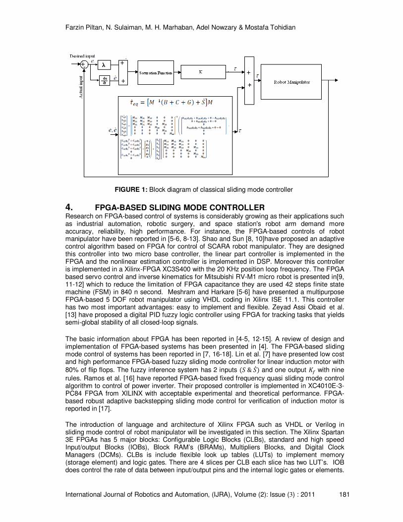
FIGURE 1: Block diagram of classical sliding mode controller
Farzin Piltan, N. Sulaiman, M. H. Marhaban, Adel Nowzary & Mostafa Tohidian
International Journal of Robotics and Automation, (IJRA), Volume (2): Issue (3) : 2011 182
It supports bidirectional data with three state operation and multiplicity of signal standards. BRAMs require the data storage including 18-Kbit dual-port blocks. Product two 18-bit binary numbers is done by multiplier blocks. Self-calibrating, digital distributing solution, delaying, multiplying, dividing and phase-shift clock signal are done by DCM [15].
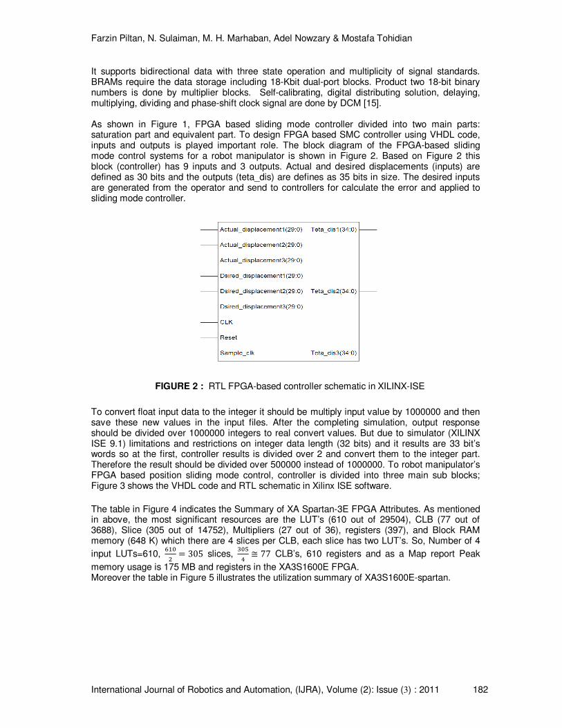
As shown in Figure 1, FPGA based sliding mode controller divided into two main parts: saturation part and equivalent part. To design FPGA based SMC controller using VHDL code, inputs and outputs is played important role. The block diagram of the FPGA-based sliding mode control systems for a robot manipulator is shown in Figure 2. Based on Figure 2 this block (controller) has 9 inputs and 3 outputs. Actual and desired displacements (inputs) are defined as 30 bits and the outputs (teta_dis) are defines as 35 bits in size. The desired inputs are generated from the operator and send to controllers for calculate the error and applied to sliding mode controller.
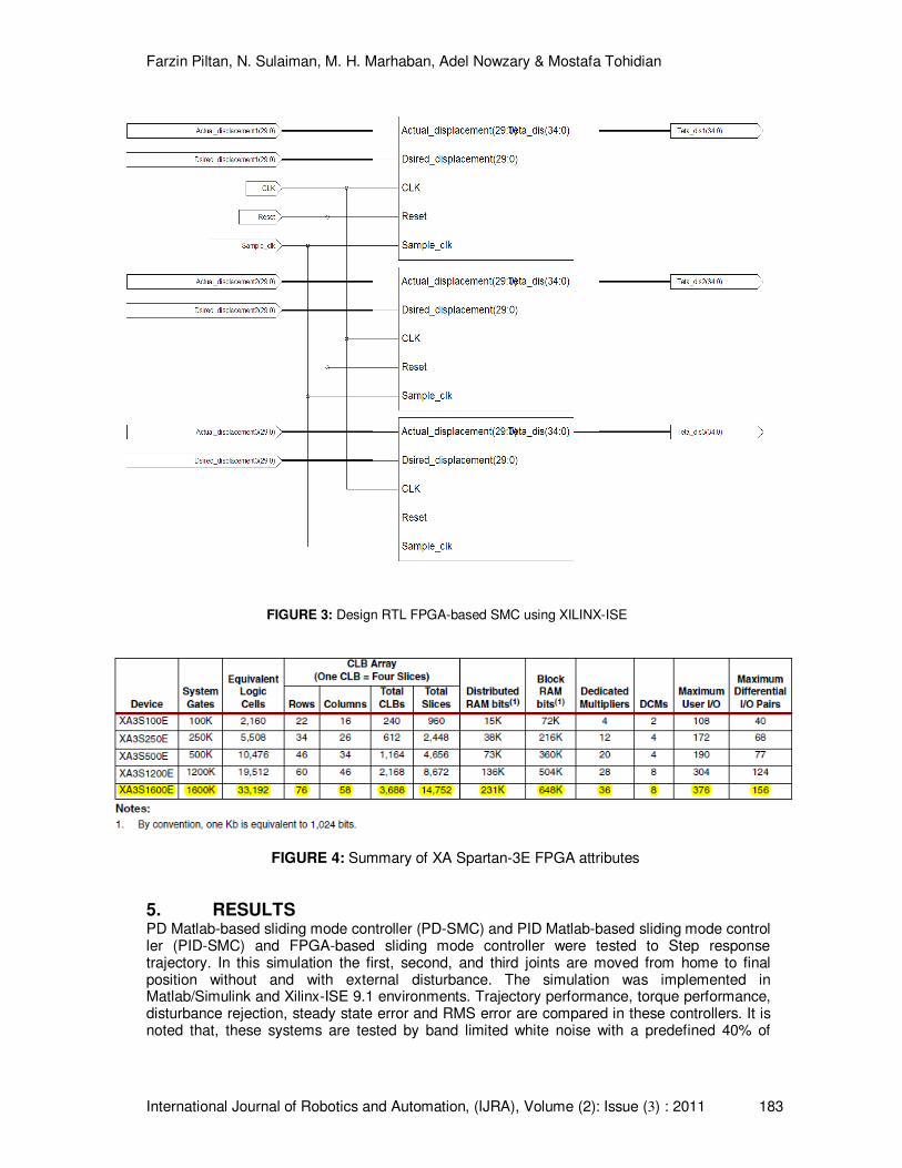
To convert float input data to the integer it should be multiply input value by 1000000 and then save these new values in the input files. After the completing simulation, output response should be divided over 1000000 integers to real convert values. But due to simulator (XILINX ISE 9.1) limitations and restrictions on integer data length (32 bits) and it results are 33 bit’s words so at the first, controller results is divided over 2 and convert them to the integer part. Therefore the result should be divided over 500000 instead of 1000000. To robot manipulator’s FPGA based position sliding mode control, controller is divided into three main sub blocks; Figure 3 shows the VHDL code and RTL schematic in Xilinx ISE software.
The table in Figure 4 indicates the Summary of XA Spartan-3E FPGA Attributes. As mentioned in above, the most significant resources are the LUT’s (610 out of 29504), CLB (77 out of 3688), Slice (305 out of 14752), Multipliers (27 out of 36), registers (397), and Block RAM memory (648 K) which there are 4 slices per CLB, each slice has two LUT’s. So, Number of 4
input LUTs=610, |}~� 305 slices,
�~�� � 77 CLB’s, 610 registers and as a Map report Peak
memory usage is 175 MB and registers in the XA3S1600E FPGA. Moreover the table in Figure 5 illustrates the utilization summary of XA3S1600E-spartan.
FIGURE 2 : RTL FPGA-based controller schematic in XILINX-ISE
Farzin Piltan, N. Sulaiman, M. H. Marhaban, Adel Nowzary & Mostafa Tohidian
International Journal of Robotics and Automation, (IJRA), Volume (2): Issue (3) : 2011 183
5. RESULTS PD Matlab-based sliding mode controller (PD-SMC) and PID Matlab-based sliding mode control ler (PID-SMC) and FPGA-based sliding mode controller were tested to Step response trajectory. In this simulation the first, second, and third joints are moved from home to final position without and with external disturbance. The simulation was implemented in Matlab/Simulink and Xilinx-ISE 9.1 environments. Trajectory performance, torque performance, disturbance rejection, steady state error and RMS error are compared in these controllers. It is noted that, these systems are tested by band limited white noise with a predefined 40% of
FIGURE 4: Summary of XA Spartan-3E FPGA attributes
FIGURE 3: Design RTL FPGA-based SMC using XILINX-ISE
Farzin Piltan, N. Sulaiman, M. H. Marhaban, Adel Nowzary & Mostafa Tohidian
International Journal of Robotics and Automation, (IJRA), Volume (2): Issue (3) : 2011 184
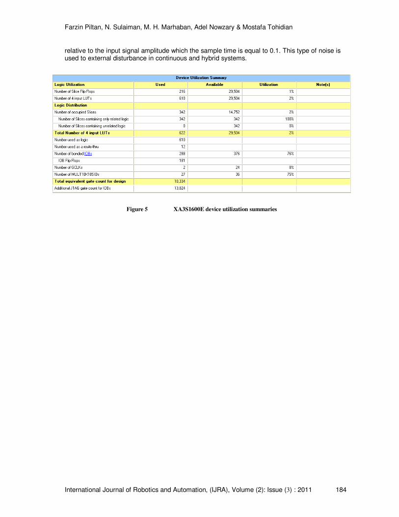
relative to the input signal amplitude which the sample time is equal to 0.1. This type of noise is used to external disturbance in continuous and hybrid systems.
5.1 Matlab-Based Sliding Mode Controller Figure 6 shows the tracking performance in PD-SMC and PID SMC without disturbance for Step trajectory. The best possible coefficients in Step PID-SMC are; z� z� z� 30, j} j� j� 0.1, ]^_ �} 3, �� 6, �� 6 as well as similarly in Step PD-SMC are; z� z� 10,j} j� j� 0.1, ]^_ �} 1, �� 6, �� 8.
Figure 5 XA3S1600E device utilization summaries
Farzin Piltan, N. Sulaiman, M. H. Marhaban, Adel Nowzary & Mostafa Tohidian
International Journal of Robotics and Automation, (IJRA), Volume (2): Issue (3) : 2011 185
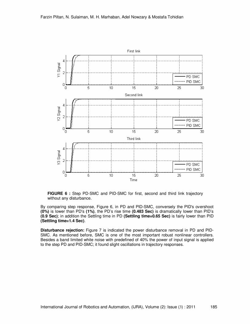
By comparing step response, Figure 6, in PD and PID-SMC, conversely the PID's overshoot (0%) is lower than PD's (1%), the PD’s rise time (0.483 Sec) is dramatically lower than PID’s (0.9 Sec); in addition the Settling time in PD (Settling time=0.65 Sec) is fairly lower than PID (Settling time=1.4 Sec).
Disturbance rejection: Figure 7 is indicated the power disturbance removal in PD and PID-SMC. As mentioned before, SMC is one of the most important robust nonlinear controllers. Besides a band limited white noise with predefined of 40% the power of input signal is applied to the step PD and PID-SMC; it found slight oscillations in trajectory responses.
FIGURE 6 : Step PD-SMC and PID-SMC for first, second and third link trajectory without any disturbance.
Farzin Piltan, N. Sulaiman, M. H. Marhaban, Adel Nowzary & Mostafa Tohidian
International Journal of Robotics and Automation, (IJRA), Volume (2): Issue (3) : 2011 186
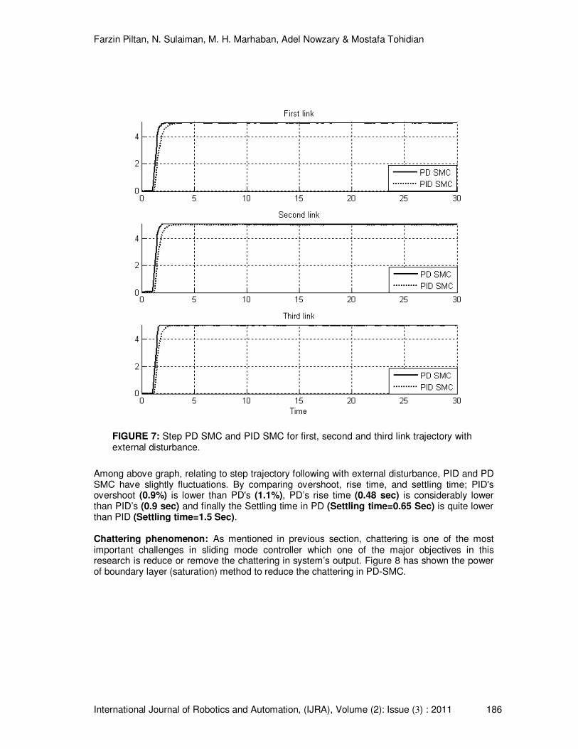
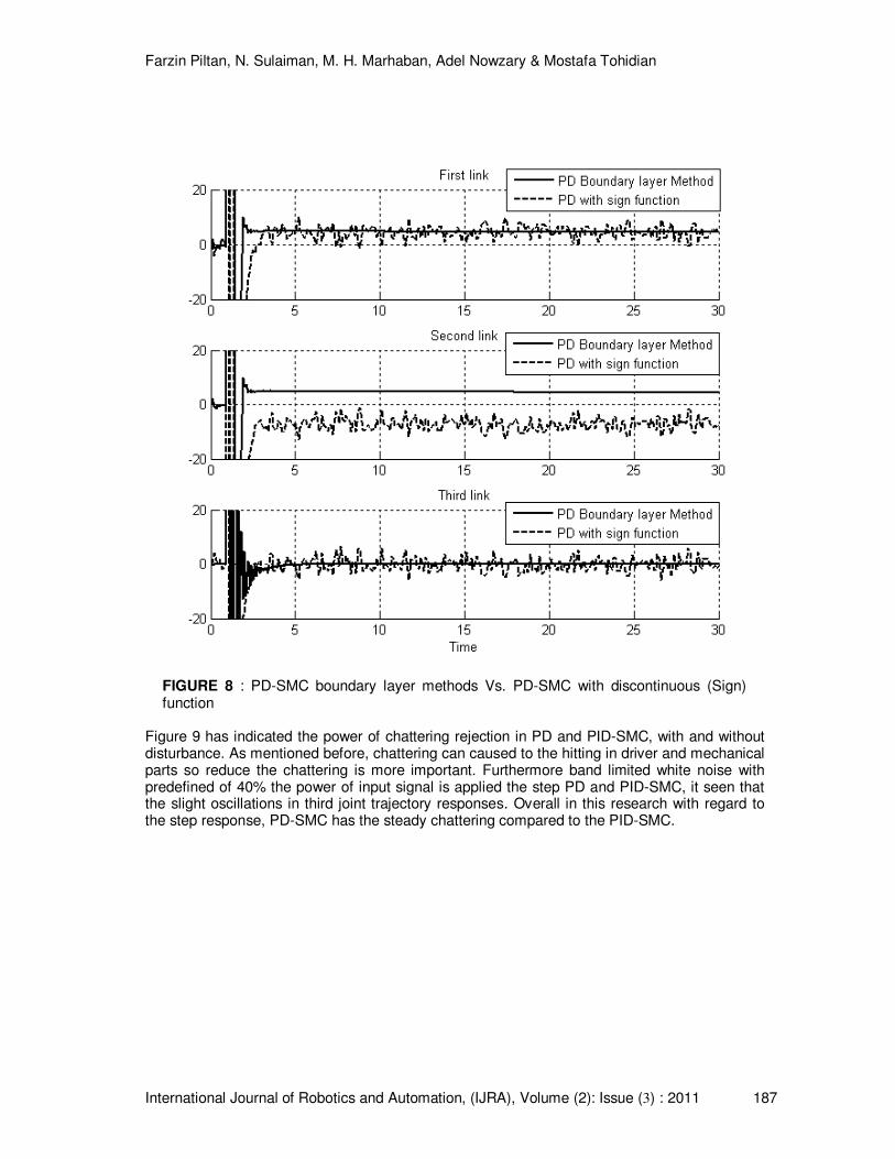
Among above graph, relating to step trajectory following with external disturbance, PID and PD SMC have slightly fluctuations. By comparing overshoot, rise time, and settling time; PID's overshoot (0.9%) is lower than PD's (1.1%), PD’s rise time (0.48 sec) is considerably lower than PID’s (0.9 sec) and finally the Settling time in PD (Settling time=0.65 Sec) is quite lower than PID (Settling time=1.5 Sec). Chattering phenomenon: As mentioned in previous section, chattering is one of the most important challenges in sliding mode controller which one of the major objectives in this research is reduce or remove the chattering in system’s output. Figure 8 has shown the power of boundary layer (saturation) method to reduce the chattering in PD-SMC.
FIGURE 7: Step PD SMC and PID SMC for first, second and third link trajectory with external disturbance.
Farzin Piltan, N. Sulaiman, M. H. Marhaban, Adel Nowzary & Mostafa Tohidian
International Journal of Robotics and Automation, (IJRA), Volume (2): Issue (3) : 2011 187
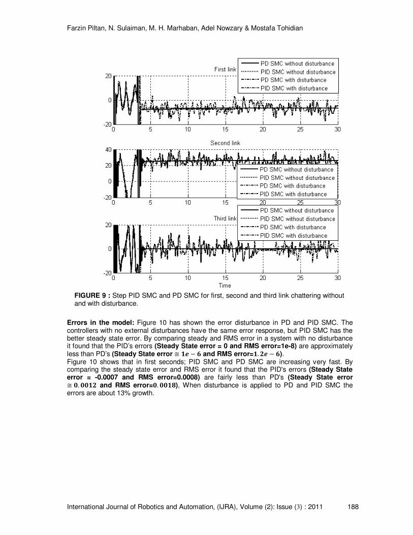
Figure 9 has indicated the power of chattering rejection in PD and PID-SMC, with and without disturbance. As mentioned before, chattering can caused to the hitting in driver and mechanical parts so reduce the chattering is more important. Furthermore band limited white noise with predefined of 40% the power of input signal is applied the step PD and PID-SMC, it seen that the slight oscillations in third joint trajectory responses. Overall in this research with regard to the step response, PD-SMC has the steady chattering compared to the PID-SMC.
FIGURE 8 : PD-SMC boundary layer methods Vs. PD-SMC with discontinuous (Sign) function
Farzin Piltan, N. Sulaiman, M. H. Marhaban, Adel Nowzary & Mostafa Tohidian
International Journal of Robotics and Automation, (IJRA), Volume (2): Issue (3) : 2011 188
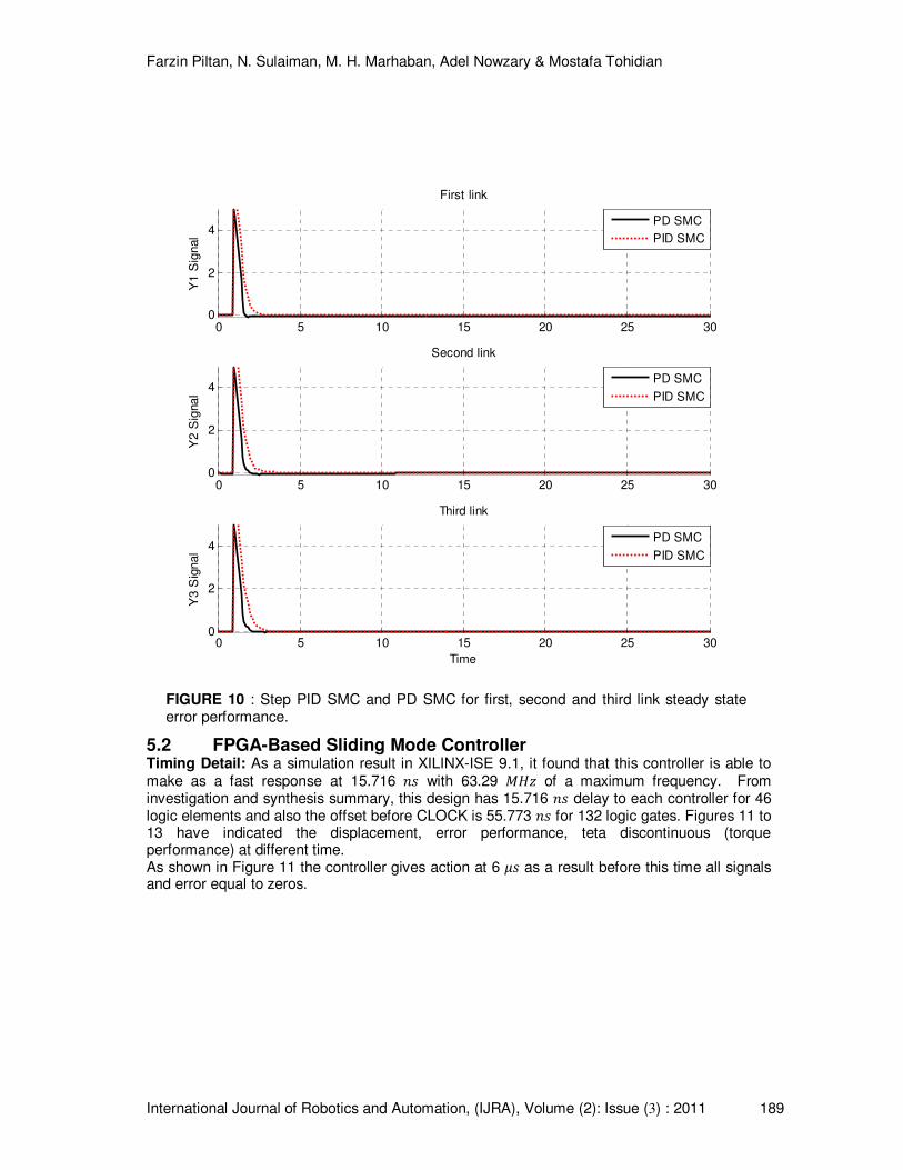
Errors in the model: Figure 10 has shown the error disturbance in PD and PID SMC. The controllers with no external disturbances have the same error response, but PID SMC has the better steady state error. By comparing steady and RMS error in a system with no disturbance it found that the PID’s errors (Steady State error = 0 and RMS error=1e-8) are approximately less than PD’s (Steady State error � �G � ) and RMS error=�. �G � )). Figure 10 shows that in first seconds; PID SMC and PD SMC are increasing very fast. By comparing the steady state error and RMS error it found that the PID's errors (Steady State error = -0.0007 and RMS error=0.0008) are fairly less than PD's (Steady State error � &. &&�� and RMS error=&. &&��), When disturbance is applied to PD and PID SMC the errors are about 13% growth.
FIGURE 9 : Step PID SMC and PD SMC for first, second and third link chattering without and with disturbance.
Farzin Piltan, N. Sulaiman, M. H. Marhaban, Adel Nowzary & Mostafa Tohidian
International Journal of Robotics and Automation, (IJRA), Volume (2): Issue (3) : 2011 189
5.2 FPGA-Based Sliding Mode Controller Timing Detail: As a simulation result in XILINX-ISE 9.1, it found that this controller is able to make as a fast response at 15.716 ^� with 63.29 ��� of a maximum frequency. From investigation and synthesis summary, this design has 15.716 ^� delay to each controller for 46 logic elements and also the offset before CLOCK is 55.773 ^� for 132 logic gates. Figures 11 to 13 have indicated the displacement, error performance, teta discontinuous (torque performance) at different time. As shown in Figure 11 the controller gives action at 6 �� as a result before this time all signals and error equal to zeros.
FIGURE 10 : Step PID SMC and PD SMC for first, second and third link steady state error performance.
0 5 10 15 20 25 300
2
4
Y1 S
ignal
First link
0 5 10 15 20 25 300
2
4
Y2 S
ignal
Second link
0 5 10 15 20 25 300
2
4
Y3 S
ignal
Time
Third link
PD SMC
PID SMC
PD SMC
PID SMC
PD SMC
PID SMC
Farzin Piltan, N. Sulaiman, M. H. Marhaban, Adel Nowzary & Mostafa Tohidian
International Journal of Robotics and Automation, (IJRA), Volume (2): Issue (3) : 2011 190
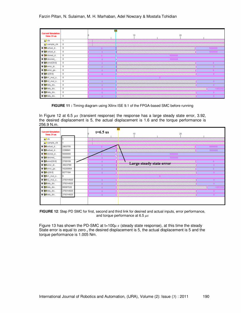
FIGURE 11 : Timing diagram using Xilinx ISE 9.1 of the FPGA-based SMC before running
In Figure 12 at 6.5 �� (transient response) the response has a large steady state error, 3.92, the desired displacement is 5, the actual displacement is 1.6 and the torque performance is 256.9 N.m.
FIGURE 12: Step PD SMC for first, second and third link for desired and actual inputs, error performance, and torque performance at 6.5 ��
Figure 13 has shown the PD-SMC at t=100� � (steady state response), at this time the steady State error is equal to zero , the desired displacement is 5, the actual displacement is 5 and the torque performance is 1.005 Nm.
Farzin Piltan, N. Sulaiman, M. H. Marhaban, Adel Nowzary & Mostafa Tohidian
International Journal of Robotics and Automation, (IJRA), Volume (2): Issue (3) : 2011 191
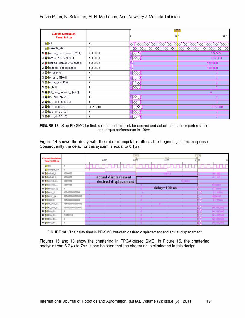
FIGURE 13 : Step PD SMC for first, second and third link for desired and actual inputs, error performance, and torque performance in 100��.
Figure 14 shows the delay with the robot manipulator affects the beginning of the response. Consequently the delay for this system is equal to 0.1� �.
FIGURE 14 : The delay time in PD-SMC between desired displacement and actual displacement
Figures 15 and 16 show the chattering in FPGA-based SMC. In Figure 15, the chattering analysis from 6.2 �� to 7��. It can be seen that the chattering is eliminated in this design.
Farzin Piltan, N. Sulaiman, M. H. Marhaban, Adel Nowzary & Mostafa Tohidian
International Journal of Robotics and Automation, (IJRA), Volume (2): Issue (3) : 2011 192
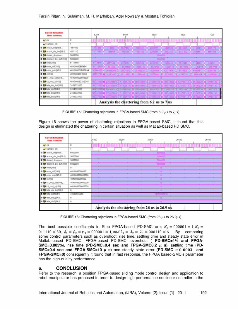
FIGURE 15: Chattering rejections in FPGA-based SMC (from 6.2 �� to 7��)
Figure 16 shows the power of chattering rejections in FPGA-based SMC, it found that this design is eliminated the chattering in certain situation as well as Matlab-based PD SMC.
FIGURE 16: Chattering rejections in FPGA-based SMC (from 26 �� to 26.9��)
The best possible coefficients in Step FPGA-based PD-SMC are; z� 000001 1, z� 011110 30, j} j� j� 000001 1, ]^_ �} �� �� 000110 6. By comparing some control parameters such as overshoot, rise time, settling time and steady state error in Matlab–based PD-SMC, FPGA-based PD-SMC; overshoot ( PD-SMC=1% and FPGA-SMC=0.005%), rise time (PD-SMC=0.4 sec and FPGA-SMC8.2 � s), settling time (PD-SMC=0.4 sec and FPGA-SMC=10 � s) and steady state error (PD-SMC � &. &&&� and FPGA-SMC=0) consequently it found that in fast response, the FPGA based-SMC’s parameter has the high-quality performance.
6. CONCLUSION Refer to the research, a position FPGA-based sliding mode control design and application to robot manipulator has proposed in order to design high performance nonlinear controller in the
Farzin Piltan, N. Sulaiman, M. H. Marhaban, Adel Nowzary & Mostafa Tohidian
International Journal of Robotics and Automation, (IJRA), Volume (2): Issue (3) : 2011 193
presence of certainties. Regarding to the positive points in sliding mode controller and FPGA the output has improved. Sliding mode controller by adding to the FPGA single chip IC has covered negative points. Obviously PUMA 560 robot manipulator is nonlinear so this paper focuses on comparison between Matlab-based sliding mode controller and FPGA-based sliding mode controller, to opt for mobility control method for the industrial manipulator.
Higher implementation speed and small chip size versus an acceptable performance is reached by designing FPGA-based sliding mode controller. This implementation considerably reduces the chattering phenomenon and error in the presence of certainties. The controller works with a maximum clock frequency of 63.29 MHz and the computation time (delay in activation) of this controller is 0.1��. As a result, this controller will be able to control a wide range of robot manipulators with a high sampling rates because it's small size versus high speed markets.
REFERENCES: [1] T. R. Kurfess, Robotics and automation handbook: CRC, 2005. [2] B. Siciliano and O. Khatib, Springer handbook of robotics: Springer-Verlag New York
Inc, 2008. [3] O. Kaynak, "Guest editorial special section on computationally intelligent
methodologies and sliding-mode control," IEEE Transactions on Industrial Electronics, vol. 48, pp. 2-3, 2001.
[4] N. Sulaiman, et al., "Design and Implementation of FPGA-Based Systems-A Review,"
Australian Journal of Basic and Applied Sciences, vol. 3, pp. 3575-3596, 2009. [5] U. Meshram, et al., "Robot arm controller using FPGA," 2009, pp. 8-11. [6] U. D. Meshram and R. Harkare, "FPGA Based Five Axis Robot Arm Controller." [7] F. J. Lin, et al., "FPGA-based fuzzy sliding-mode control for a linear induction motor
drive," 2005, pp. 1137-1148. [8] X. Shao and D. Sun, "Development of an FPGA-based motion control ASIC for robotic
manipulators," 2006, pp. 8221-8225. [9] Y. S. Kung, et al., "FPGA-implementation of inverse kinematics and servo controller for
robot manipulator," Proc. IEEE Int. on Robotics and Biomimetics, pp. 1163–1168, 2006.
[10] X. Shao, et al., "A new motion control hardware architecture with FPGA-based IC
design for robotic manipulators," 2006, pp. 3520-3525. [11] Y. S. Kung, et al., "Design and Implementation of a Servo System for Robotic
Manipulator," ed: CACS, 2005. [12] Y. S. Kung and G. S. Shu, "Development of a FPGA-based motion control IC for robot
arm," 2006, pp. 1397-1402. [13] Z. A. Obaid, et al., "Developed Method of FPGA-based Fuzzy Logic Controller Design
with the Aid of Conventional PID Algorithm," Australian Journal of Basic and Applied Sciences, vol. 3, pp. 2724-2740, 2009.
[14] S. T. Karris, Digital circuit analysis and design with Simulink modeling and introduction
to CPLDs and FPGAs: Orchard Pubns, 2007.
Farzin Piltan, N. Sulaiman, M. H. Marhaban, Adel Nowzary & Mostafa Tohidian
International Journal of Robotics and Automation, (IJRA), Volume (2): Issue (3) : 2011 194
[15] K. D. Rogers, "ACCELERATION AND IMPLEMENTION OF A DSP PHASE-BASED FREQUENCY ESTIMATION ALGORITHM: MATLAB/SIMULINK TO FPGA VIA XILINX SYSTEM GENERATOR," Citeseer, 2004.
[16] R. R. Ramos, et al., "A fixed-frequency quasi-sliding control algorithm: application to
power inverters design by means of FPGA implementation," Power Electronics, IEEE Transactions on, vol. 18, pp. 344-355, 2003.
[17] F. J. Lin, et al., "FPGA-based adaptive backstepping sliding-mode control for linear
induction motor drive," Power Electronics, IEEE Transactions on, vol. 22, pp. 1222-1231, 2007.
[18] S. Lentijo, et al., "FPGA based sliding mode control for high frequency power
converters," 2004, pp. 3588-3592.