Design of experimental set-up for establishing empirical ...
13
779 Design of experimental set-up for establishing empirical relationship for chaff cutter energized by human powered flywheel motor P.B. Khope 1 and J.P. Modak 2 1 Research Scholar and Assistant Professor, Department of Mechanical Engineering, Priyadarshini College of Engineering, Nagpur, Maharashtra, India, 2 Emeritus Professor (AICTE) and Dean (R&D), Department of Mechanical Engineering, Priyadarshini College of Engineering, Nagpur, Maharashtra, India P.B. Khope and J.P. Modak (2013) Design of experimental set-up for establishing empirical relationship for chaff cutter energized by human powered flywheel motor. Journal of Agricultural Technology 9(4):779-791. A human powered chaff cutter has been developed in the absence of any data. Literature survey reveals thata system for pumping using muscular energy in the flywheel is feasible and then the energy stored in flywheel can used for different applications. Accordingly, it was decided to work on chaff cutter with this concept and to establish an empirical relationship for human powered chaff cutting process. Since this is a man-machine system, it is rather difficult and unreliable to adopt total theoretical approach for the development, thus, the experimental approach was adopted. This set up consists of three subsystems namely. (i) Human powered flywheel motor (HPFM) i.e. energy unit. (ii)Torque amplification gears and clutch unit and (iii) process unit i.e. chaff cutter. This paper reports the design of experimental setup for carrying out the experimentation to establish empirical relationship for chaff cutter energized by human powered flywheel motor. Key words: Human powered Flywheel Motor, Chaff cutter. Introduction In India, animal husbandry is an integral part of the rural economy. The forage (dry or wet) production requires high labor, coupled with a lack of sufficient land for forage. Production and forage scarcity during the dry season means that available forage must be efficiently used to minimize waste. Traditionally, the farmers chop forage into small pieces for easy consumption by the animals as shown in Figure1. This method is tedious, time consuming and quite dangerous to operator, as well as low output and lack of Corresponding author : P.B. Khope; e-mail: [email protected] Journal of Agricultural Technology 2013 Vol. 9(4): 779-791 Available online http://www.ijat-aatsea.com ISSN 1686-9141
Transcript of Design of experimental set-up for establishing empirical ...

Journal of Agricultural Technology 2013, Vol. 9(4): 779-791
779
Design of experimental set-up for establishing empirical
relationship for chaff cutter energized by human powered
flywheel motor
P.B. Khope1
and J.P. Modak2
1Research Scholar and Assistant Professor, Department of Mechanical Engineering,
Priyadarshini College of Engineering, Nagpur, Maharashtra, India, 2Emeritus Professor
(AICTE) and Dean (R&D), Department of Mechanical Engineering, Priyadarshini College of
Engineering, Nagpur, Maharashtra, India
P.B. Khope and J.P. Modak (2013) Design of experimental set-up for establishing empirical
relationship for chaff cutter energized by human powered flywheel motor. Journal of
Agricultural Technology 9(4):779-791.
A human powered chaff cutter has been developed in the absence of any data. Literature survey
reveals thata system for pumping using muscular energy in the flywheel is feasible and then the
energy stored in flywheel can used for different applications. Accordingly, it was decided to
work on chaff cutter with this concept and to establish an empirical relationship for human
powered chaff cutting process. Since this is a man-machine system, it is rather difficult and
unreliable to adopt total theoretical approach for the development, thus, the experimental
approach was adopted. This set up consists of three subsystems namely. (i) Human powered
flywheel motor (HPFM) i.e. energy unit. (ii)Torque amplification gears and clutch unit and (iii)
process unit i.e. chaff cutter. This paper reports the design of experimental setup for carrying
out the experimentation to establish empirical relationship for chaff cutter energized by human
powered flywheel motor.
Key words: Human powered Flywheel Motor, Chaff cutter.
Introduction
In India, animal husbandry is an integral part of the rural economy. The
forage (dry or wet) production requires high labor, coupled with a lack of
sufficient land for forage. Production and forage scarcity during the dry season
means that available forage must be efficiently used to minimize waste.
Traditionally, the farmers chop forage into small pieces for easy
consumption by the animals as shown in Figure1. This method is tedious, time
consuming and quite dangerous to operator, as well as low output and lack of
Corresponding author : P.B. Khope; e-mail: [email protected]
Journal of Agricultural Technology 2013 Vol. 9(4): 779-791
Available online http://www.ijat-aatsea.com ISSN 1686-9141

780
uniformity. Presently mechanized forage cutters are electric motor driven or
hand driven. But today, there is huge scarcity of electricity almost everywhere
in India, which results in six totwelve hours load shedding. The power cut (load
shedding) badly affects daily needs that require power supply. Hand muscles
are weaker than leg muscles, so it can be used in muscle-driven flywheel motor
to replace the electric driven cutting unit.
Fig. 1. Traditional hand chopping
Materials and methods
Formulation of the Present Problem
In the human powered flywheel motor concept, the bicycle mechanism
for converting and transmitting human energy through paddling to rotational
kinetic energy of flywheel is hereby proposed. The energy stored in the
flywheel can then used for actual cutting process. This human energy output is
in the low range and the processes could be operated intermittently can be
considered for utilization. Modak (2004) gave a landmark paper, in which he
presented reports on (1) functional feasibility and (2) economic viability of
human powered flywheel motor. A schematic representation of the set-up is
given in figure 2. A driver sits on seat and paddles the bicycle mechanism
converting oscillating motion of things into rotational motion of flywheel with
increasing speed.

Journal of Agricultural Technology 2013, Vol. 9(4): 779-791
781
Fig. 2. Schematic of Human Powered Flywheel Motor.
1-Chain Sprocket 2-Pedal 3-Chain 4-Freewheel 5,6-Bearings for bicycle side 7-Gear-I 8-
Bearing 9-Tachogenerator for flywheel shaft 10-Pinion-I 11-Bearing for flywheel shaft 12-
Flywheel 13-Bearing for flywheel 14-Two jaw clutch 15,15-Bearing of intermediate shaft 17-
Pinion II 18-Gear II 19,20-Bearing for process unit shaft21-Coupling 22-Chaff Cutter blade 23-
Tachogenerator for chaff Cutter shaft
The load on the thighs (legs) of the rider is only the inertia load of the
flywheel. The rider pumps energy in the flywheel at an energy input rate
convenient to him. Thus, this man-machine system brings out ways for energy
conversion of human muscular energy into rotational kinetic energy of
flywheel. It was necessary to develop the energy unit of this man-machine
system for chaff cutter scientifically. An approach of methodology of
experimentation (Schenk, 1962) is adapted and worked out for the detailed
design of experimentation for chaff cutter.
Formulation of the dimensional Equations
Dimensional Analysis of the parameters affecting the chaff cutter
energized by human powered flywheel motor was identified and listed in Table
1. Dimensional analysis was used to express the required functional
relationship between the different parts of the chaff cutting process. The main
advantage of this analysis is the reduction of the number of variables.
Dimensional equations for response variables is :
1. Resistive Torque (Tc) :
(D/gI) Tc = f {( dWbtb/D3 ),(D
4/gI) E,G,n, α, ,(√D/g) ω,(√g/d)tc,} (1)
2. Number of cuts (Cp):
(√D/g)Cp =f{( dWbtb/D3
),(D4/gI) E,G,n, α, ,(√D/g) ω,(√g/d)tc,} (2)

782
3. Process time for cutting (tp):
(√g/D)tp = f{( dWbtb/D3
),(D4/gI) E,G,n, α, ,(√D/g) ω,(√g/d)tc,} (3)
Where: d = Hub Diameter of blade Wb = Width of cutting blade
tb = Thickness of cutting blade D = Tip diameter of blade
g = Acceleration due to gravity I = Moment of inertia of flywheel
E = Young’s modulus of elasticity of cutting blade = Cutting blade angle
G = Gear ratio n = Number of blades
e = Kinetic energy of flywheel ω = Angular velocity
Tc = Instantaneous torque on cutting blade Cp = Number of cuts during cutting
tp = Process time for cutting
Table 1. Dimensional Matrix
d Wb tb D g I E n ω tc e G Tc Cp tp
M 0 0 0 0 0 0 1 0 0 0 0 1 0 1 0 0
L 1 1 1 1 1 1 -2 0 0 0 0 2 0 2 0 0
T 0 0 0 0 -2 -2 -1 0 0 -1 1 -2 0 -2 0 1
The variables listed were combined to from dimensionless ratio or π terms on the basis of
nature of physical quantities. These formed groups have been used for experimentation, as
given in Table 2.
Table 2. Dimensionless ratio or π terms
Sr.
No.
Independent dimensionless ratio or π
terms
Nature of basic physical quantities
1
Geometric Variables
2
Material of blade
3
Instantaneous Terminal velocity of
cutter
4 Gear Ratio
5 Cutting blade angle
6 No. of cutting blade
7
Cutting time
8
Terminal speed of flywheel
9
Resistive torque

Journal of Agricultural Technology 2013, Vol. 9(4): 779-791
783
10
No. of cuts by cutter
11
Process time
Finalization of Test Envelope and Test Point
It is necessary to decide the range of parameters which would be varied
during experimentation. The test envelope, test points and test sequence for
every independent π terms is given in Table 2.
Table 2. The test envelope, test points and test sequence
Sr.
No
Ratio Test
Envelop
Range
Test
Point
Test Sequence
1 2 3 4
01 π 1 =dWbtb/D3 5.33×10⁻³ Constant
02 π2 =(D4/gI)E 1.46×10⁹ Constant
03 π 3= G 2,3,4 2.3.4 2.3.4 2.3.4 2.3.4 2.3.4 2.3.4 2.3.4 2.3.
4
04 π 4 = α 0.122 Constant
05 π5 =n 2,3 2 3 2 3 2 3 2 3
06 π 6= (D/2g)ωf2 31.428-62.857
31.426 41.904 52.380 62.857
Next step is to design and fabrication of an experimental set-up for the
proposed experimentation.
Design of Experimental set up
Flywheel
2 2
s m
Wk K
g
(4)
Where,
Ks = Coefficient of speed Fluctuation, E = The maximum fluctuation of energy. k = Radius
of gyration
Ks = {0.12[Do2 + (Do – 2h)
2]}
1/2
m = mean velocity in radians/second, h = rim thickness, b = rim width
Considering E = 42,035 J
( 2 2
max min
1 1
2 2I I
) (5)

784
max mins
mean
N NK
N
2 2
s m
Wk K
g
2 2
s m
2
s m
= mk K ω
=IK ω
Where,
I = Moment Of Inertia of Flywheel.
E = 42,035 J, Ks = 2, m 41.866 rad/sec
E = 2
s mIK ω
42,035 = I 2 (41.866)2
I = 11.99 kg-m2
We consider, I = 12 kg-m2
Assume Dm = flywheel mean diameter. =0.98m k = 0.49m
Assuming that the rim provides 95 percent of the required moment of inertia,
mk2
= 0.95 I = 0.9512=11.4 (6)
m =11.4/ k2
= 11.4/0.492 m = 47.48 kg
Other dimensions of flywheel:
b = 100 mm, h = 19.7mm, Do = 1000 mm, No. of arms = 6.
Stresses in the flywheel:
Centrifugal stress = 13.53 MPa, Bending stress = 187.21 MPa, resultant stress
= 56.79 MPa
Chain Drive
Rated Power, PR= 900 W, Design Power(Pd) : PrK1 (7) Where,
K1 =Load Factor, From design data book it should be 1.2 for moderate shock and service of 10
hours per day [Shiwalkar B. D., 2004).
Pd = 900 1.2 =1080 W =1.44 hp
Speed of smaller sprocket = 120 rpm.
From design data book graph, chain No. 50 for which Pitch (p) = 15.875 was
selected. The chain sprocket with the 24 teeth on the smaller sprocket and 48
teeth on the larger sprocket is available in the market.
Pitch Diameter of smaller Sprocket (Dp2)

Journal of Agricultural Technology 2013, Vol. 9(4): 779-791
785
p2
2
D =180
sin
p
T
(8)
T2 = No. of teeth on smaller sprocket = 24
p2
1.1875D =
180sin
24
=106.5 mm
Pitch Line Velocity(Vp) :
Vp2= ( Dp2N2)/60 = (3.14106.510-3120)/60, Vp2 = 0.66 m/sec
Power capacity per strand:
1.41
2 318026 25cos 10
104 526
V VP p
T
(9)
where, p= chain pitch=15.875mm, V =Vp2 =0.66m/sec , T =T2 =21
1.41
2 30.66 0.66 18015.875 26 25cos 10
104 526 24P
P = 1275.6W
No. of strands = 1080/1275.6 =0.84
No. of strands =1
Tooth Load (Ft) = Pd/Vp = 1080/0.66 = 1636.36 N
Other dimensions
Pitch diameter of larger sprocket = 232.17 mm, center distance C =
120.82 mm, recommended Cmin = 285.42mm, length of chain in pitch Lp =
72.75, Outer Diameter of the smaller sprocket = 130.10 mm, outer diameter of
the larger sprocket = 251.73mm, width of the sprocket 9 mm.
Gear Design (Stage 1)
Pd = 2000 W, Module = m, pitch diameter, Dp=20m,
Vp = 0.8373m,
Ft = Pd/Vp = 2000/0.8373m = 2388.63/m
Assuming 1045 steel with heat treatment, So= 210 MPa, (Shiwalkar B. D.,
2004; Bhandari V.B.(2005).
Bending strength,
Fb = So.Cv.b.Y.m =2100.300.341510mm = 21.145m2
Basic strength, So = 210 MPa
Velocity factor, Cv=0.3 (trial value), face width of gears, b= 10m (trial value.)
Modified Lewis form factor,
786
Y = 0.485 – 2.87/tp = 0.485 - 2.87/20 = 0.3415
Fb = 215.145m2
Equating Fb = Ft ,215.145m2
= 2388.63/m, m = 2.23, select module, m = 3.
Dp =m.tp = 320 = 60 mm.
After calculation, the actual values of Vp, Cv and Ft are as follows :
Vp= 2.5119 m/sec, Cv = 0.544, Ft = 796.21 N
Calculated dimensions for other gears
Pinion Gear
m=3 m=3
T=20 t=80
Dp=60mm Dp=240mm
Design of shaft
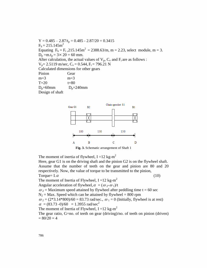
Fig. 3. Schematic arrangement of Shaft 1
The moment of inertia of flywheel, I =12 kg-m2
Here, gear G1 is on the driving shaft and the pinion G2 is on the flywheel shaft.
Assume that the number of teeth on the gear and pinion are 80 and 20
respectively. Now, the value of torque to be transmitted to the pinion,
Torque= I. (10)
The moment of Inertia of Flywheel, I =12 kg-m2
Angular acceleration of flywheel, = ( 2- 1)/t
2 = Maximum speed attained by flywheel after peddling time t = 60 sec
N2 = Max. Speed which can be attained by flywheel = 800 rpm
2 = (2*3.14*800)/60 = 83.73 rad/sec., 1 = 0 (Initially, flywheel is at rest)
= (83.73 -0)/60 = 1.3955 rad/sec2
The moment of Inertia of Flywheel, I =12 kg-m2
The gear ratio, G=no. of teeth on gear (driving)/no. of teeth on pinion (driven)
= 80/20 = 4

Journal of Agricultural Technology 2013, Vol. 9(4): 779-791
787
The load torque can be overcome (because of the M.I.) of the flywheel=I. =
G.I. =41283.73 = 66.984 N-m.
The maximum torque to be transmitted from gear G1 to the pinion G2 =66.984
N-m.
Fig. 4. Forces in vertical plane on Shaft 1
FGV = tangential force acting on gear tooth, FGC = radial force acting on the gear
tooth
T = FGV r (r = pitch circle radius of gear) , T = Torque
66.984 = FGV120
FGV = 558.2 N, FGV = 558.2 N, FGC = 558.2
tan20 = 203.168 N
Let Ft be the tension in the chain
Ft .(p2D
2) = 558.2120, Ft (106.51/2) = 558.2120, Ft = 1257.79 N
FBV + FDV = 558.2
-8.2100 - FDV300 = 0
FDV = (-558.2100) / 300 = -186 N
FBV = 744.2 N
Bending moment at A =0
Bending moment at B = -558.2100 = -55820 N-mm
Bending moment at C = -186 150 = -27900 N-mm
Bending moment at D = 0
Forces in H.P.
FBH + FDH = FGC +Ft
FBH + FDH = 203.168 + 1257.79 = 1460.98
M@B = 0
203.168100 + 1257.79150 +FDH 300 = 0

788
FDH = 561.17, FBH = 899.788
Bending moment at A =0
Bending moment at B = 203.16 100 = 20316.8 N-mm
Bending moment at C = -561.17 150 = -84175.5. N-mm
Bending moment at D = 0.
Resultant Bending Moment at B = 2 255820 20316.8 = 59402.39 N-mm
Resultant Bending Moment at C = 2 227900 84175.5 = 88678.77 N-mm
Maximum Bending Moment = M = 88678.77 N-mm
Selecting Material of shaft as SAE1030 for which :
Syt = 296MPa & Sut = 527Mpa, max < 0.30Syt or max < 0.18 Sut
Therefore the design shear stress should be
Sds = 0.30Syt = 0.30*296 = 88.8MPa or Sds = 0.18 Sut= 0.18*527 =94.86 MPa
We consider provision for Keyways, Sds should be reduced by 25 percent
Sds = 0.75*88.8 =66.6 Mpa , max = 66.6 Mpa
D = 18.54mm
If we consider the factors for gradually load
Kb =1.5 & Kt = 1 (Bhandari V.B.,2005; Shiwalkar B. D.,2004),
By Calculation, D = 22.5 mm. Select D = 25 mm.
Similarly by calculations,
Diameter of shaft 2, D = 25.13 mm. Select D = 30 mm.
Diameter of shaft 3, D = 25.51 mm. Select D = 30 mm.
Bearing
For shaft 1:
The horizontal and vertical components of the reactions at two bearings B1 &
B2 are already calculated while designing the shaft.
The reactions at two bearings are given by: 2 2 2 2
B1 DH DVR = R +R = 561.17 +186 = 591.19 N (11)
2 2 2 2
B2 BH BVR = R +R = 899.788 +744.2 =1167.66 N
The expected bearing life (L10) :
10h10 6
60×n×LL =
10 (12)
Where, n = speed of rotation of shaft= 200 rpm.
L10h = Expected bearing life = 20000 hours (for the machines used for eight
hours of service per day –
L10 = (6020020000)/106
= 240 million revolutions.
The dynamic load carrying capacity (C1 & C2):
Load factor = 1.5 (for Chain Drive)
C1 = P1[L10]1/3
(Load Factor)

Journal of Agricultural Technology 2013, Vol. 9(4): 779-791
789
Considering no axial load, P1 =RB1=591.19 N
C1 = 591.192401/31.5 = 5510.89 N
C2 = P2[L10]1/3
(Load Factor)
Considering no axial load, P2 =RB2=1167.66 N
C2 = 1167.66 2401/31.5 = 10884.57 N
For the Shaft diameter 25 mm following Bearings are available:
i) No. 61805 (C =3120 N), ii) No. 16005 (C = 7610 N), iii) No. 6005 (C
=11200 N)
For required dynamic load carrying capacity, bearing no. 6005 is suitable for
B1 & B2.
Other dimensions of the bearing:
Inner diameter of the bearing = 25 mm, outer diameter of the bearing = 47 mm,
Axial width of the bearing = 12 mm.
Similarly by calculations,
Bearings available for shaft 2 and 3,
i) No. 61806 (C =3120 N), ii) No. 16006 (C = 11200 N), iii) No. 6006 (C
=13300 N ).
For required dynamic load carrying capacity, Bearing No. 16006 is suitable at
B3 & B4.
Other dimensions of the bearing:
Inner diameter of the bearing = 30 mm, Outer diameter of the bearing =55 mm,
Axial width of the bearing = 9 mm.
An experimental set-up for human powered chaff cutter (Fig. 5) was developed,
constructed and tested.
Fig. 5. View of the experimental set-up.

790
Results and discussions
The assembly was checked for its sturdiness and was found to be reliable.
There were no vibrations in the set-up. The driver paddles for 1 minute and it
was noticed that the flywheel shaft reached a speed of 350 RPM with a gear
ratio of 1:2. The paddling was stopped after one minute and the set-up was
checked for its free running. The flywheel shaft came to rest after 25 minutes. It
proved that the alignment of bearing and other parts of the experimental set-up
was satisfactory. Thus now the experimental set-up is ready to perform the
desired task.
The developed machine is similar to that reported by Dhale and Modak
(2010), wherein they formulated the approximate generalized data based model
for oilseed presser using human powered flywheel motor as an energy source.
Other human powered machines had been developed such as the one used for
lime-fly ash-sand bricks (Modak, 1882), manually driven flywheel motor that
operates on wood turning process (Modak and Bapat, 1993) and manually
powered apparatus for keyed bricks production (Sohoni, et al., 1997).
The output of this research coincides with the research of Deshpande et
al. (2009), who had confirmed the application of human powered flywheel
motor as an energy source for rural generation of electrical energy for rural
applications along with computer aided analysis of battery charging process.
Acknowledgements
The full financial support of Rajiv Gandhi Science & Technology Commission,
Government of Maharashtra to the successful completion of this research is
hereby greatly acknowledged.
References
Askhedkar R.D. and Modak J.P. (1994). Hypothesis for the Extrusion of Lime-Fly-ash-Sand
Bricks Using Manually Driven Brick Making Machine. Building Research &
Information U.K. 22(1): pp. 47-54.
Bhandari V.B. (2005). Design of Machine Elements, Tata McGraw Hill Publication, India.
Deshpande S.B., Modak, J.P. and Tarnekar, S.B. (2009). Confirming Application of human
powered flywheel motor as an energy source for rural generation of electrical energy for
rural applications, and computer aided analysis of battery charging process. Human
Power, USA International Human Power Vehicle Association 58:10-16.
Dhale, A. and Modak, J.P. (2010). Formulation of the approximate generalized data based
model for oilseed presser using human powered flywheel motor as an energy source”
International Journal of Agricultural Engineering 3(2):348-354.
H. Schenk Jr. (1962). Theories of Engineering Experimentation”, McGraw Hill Book Co., New
York, pp. 101.

Journal of Agricultural Technology 2013, Vol. 9(4): 779-791
791
Modak, J.P. (1982) Manufacturing of Lime-fly ash-sand bricks using manually driven brick
making machine. Project report, a project sponsored by Maharashtra Housing & Area
Development Authority, (MHADA), Bombay, India.
Modak, J.P. and Bapat, A.R.( 1993). Manually driven flywheel motor operates wood turning
process. Contemporary Ergonomics, Proc. Ergonomics Society Annual Convention 13-
16 April, Edinburgh, Scotland, pp. 352-357.
Modak, J.P. and Bapat, A.R. (1994). Formulation of Generalized Experimental Model for a
Manually Driven Flywheel Motor and its Optimization, Applied Ergonomics, U.K.
25(2):119-122.
Modak, J.P. and Katpatal A.A. (1994). Design of Manually Energized Centrifugal Drum Type
Algae Formation Unit. Proceedings International AMSE Conference on System,
Analysis, Control and Design, Layon (France), (3):227-232.
Modak J.P. and Bapat A.R. (2003).Various efficiency of a Human Power Flywheel motor.
Human Power, USA International Human Power Vehicle Association 54:21-23.
Modak J.P. (2004). Design and development of manually energized process machines having
relevance to village / agriculture and other productive operations. Human Power, USA,
International Human Power Vehicle Association, 57:16-22.
Modak, J.P. (2005). “Influence of development and human powered process machine and its
impact on energy management of rural and interior sector”, Proceeding of National
Conference on Energy Management in Changing Business Scenario, (EMCBS 2005),
BITS Pilani.
Shiwalkar, B.D. (2004). Design Data for Machine Elements, Denett & Co., India.
Sohoni, V.V., H.P. Aware and Modak, J.P. (1997). Manually Powered Manufacture of Keyed
Bricks, Building Research & Information, U.K. 25(6):354-364.
(Received 14 January 2013; accepted 30 June 2013)