DESIGN OF CYCLONE AND STUDY OF ITS ... aim of study is to design a cyclone for flour mill...
6
247 Int. J. Mech. Eng. & Rob. Res. 2014 Mahesh R Jadhav, 2014 ISSN 2278 – 0149 www.ijmerr.com Vol. 3, No. 4, October, 2014 © 2014 IJMERR. All Rights Reserved Research Paper DESIGN OF CYCLONE AND STUDY OF ITS PERFORMANCE PARAMETERS Mahesh R Jadhav 1 * *Corresponding Author: Mahesh R Jadhav [email protected] Cyclone is most commonly used device to separate dust particles from gas and dust flow. The project presents design development of cyclone based on CFD along with experimental trials. The present work is based on the performance of flour mill cyclone for different flow rates. In the present investigation the characteristics of flour mill cyclone are studied for various flow rates (inlet velocities) and its effect on performance parameters like pressure drop and efficiency are studied. Cyclone is designed with two symmetrical tangential inlets and a single tangential outlet at the barrel top area where impeller is mounted. The study was performed for gas-solid flow, based on an experimental study available in the literature, where a conventional cyclone model was used. Simulation of flow will be done with the help of CFD software and verification will be done with the help of experimental work. Results showed that these new designs can improve the cyclone performance parameters significantly and very interesting details were found on cyclone fluid dynamics properties. Keywords: Cyclone, Pressure drop, Double symmetrical inlet, Tangential outlet, Collection efficiency 1 Department of Mechanical Engineering, PVP Institute of Technology, Pune University, Pune, Maharashtra, India. INTRODUCTION This cyclone separator provides a method of removing particulate matter from air streams at low cost and low maintenance. In general, a cyclone consists of an upper cylindrical part referred to as the barrel and a lower conical part referred to as shown in Figure 1. The air stream enters tangentially at the top of the barrel and travels downward into the cone forming an outer vortex. The solid particles entering the cyclone immediately bifurcate into two layers of dust due to the eddy current based on the secondary flow on the upper cover surface in the coaxial space between cyclone body and exit pipe. One of them goes around the coaxial space on the upper cover surface and rotates around the exit pipe with the gas flow. The other rotates and descends along the surface of the cyclone body. Then, on the surface of the cone, the dust layer, which is pressed onto the cone surface by the centrifugal force, descends aided by
Transcript of DESIGN OF CYCLONE AND STUDY OF ITS ... aim of study is to design a cyclone for flour mill...

247
Int. J. Mech. Eng. & Rob. Res. 2014 Mahesh R Jadhav, 2014
ISSN 2278 – 0149 www.ijmerr.com
Vol. 3, No. 4, October, 2014
© 2014 IJMERR. All Rights Reserved
Research Paper
DESIGN OF CYCLONE AND STUDY OF ITS
PERFORMANCE PARAMETERS
Mahesh R Jadhav1*
*Corresponding Author: Mahesh R Jadhav � [email protected]
Cyclone is most commonly used device to separate dust particles from gas and dust flow. Theproject presents design development of cyclone based on CFD along with experimental trials.The present work is based on the performance of flour mill cyclone for different flow rates. In thepresent investigation the characteristics of flour mill cyclone are studied for various flow rates(inlet velocities) and its effect on performance parameters like pressure drop and efficiency arestudied. Cyclone is designed with two symmetrical tangential inlets and a single tangentialoutlet at the barrel top area where impeller is mounted. The study was performed for gas-solidflow, based on an experimental study available in the literature, where a conventional cyclonemodel was used. Simulation of flow will be done with the help of CFD software and verificationwill be done with the help of experimental work. Results showed that these new designs canimprove the cyclone performance parameters significantly and very interesting details werefound on cyclone fluid dynamics properties.
Keywords: Cyclone, Pressure drop, Double symmetrical inlet, Tangential outlet,Collection efficiency
1 Department of Mechanical Engineering, PVP Institute of Technology, Pune University, Pune, Maharashtra, India.
INTRODUCTION
This cyclone separator provides a method ofremoving particulate matter from air streamsat low cost and low maintenance. In general,a cyclone consists of an upper cylindrical partreferred to as the barrel and a lower conicalpart referred to as shown in Figure 1. The airstream enters tangentially at the top of thebarrel and travels downward into the coneforming an outer vortex. The solid particlesentering the cyclone immediately bifurcate
into two layers of dust due to the eddy currentbased on the secondary flow on the uppercover surface in the coaxial space betweencyclone body and exit pipe. One of them goesaround the coaxial space on the upper coversurface and rotates around the exit pipe withthe gas flow. The other rotates and descendsalong the surface of the cyclone body. Then,on the surface of the cone, the dust layer,which is pressed onto the cone surface bythe centrifugal force, descends aided by
248
Int. J. Mech. Eng. & Rob. Res. 2014 Mahesh R Jadhav, 2014
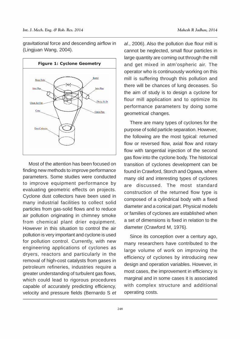
gravitational force and descending airflow in(Lingjuan Wang, 2004).
Figure 1: Cyclone Geometry
Most of the attention has been focused onfinding new methods to improve performanceparameters. Some studies were conductedto improve equipment performance byevaluating geometric effects on projects.Cyclone dust collectors have been used inmany industrial facilities to collect solidparticles from gas-solid flows and to reduceair pollution originating in chimney smokefrom chemical plant drier equipment.However in this situation to control the airpollution is very important and cyclone is usedfor pollution control. Currently, with newengineering applications of cyclones asdryers, reactors and particularly in theremoval of high-cost catalysts from gases inpetroleum refineries, industries require agreater understanding of turbulent gas flows,which could lead to rigorous procedurescapable of accurately predicting efficiency,velocity and pressure fields (Bernardo S et
al., 2006). Also the pollution due flour mill iscannot be neglected, small flour particles inlarge quantity are coming out through the milland get mixed in atm’ospheric air. Theoperator who is continuously working on thismill is suffering through this pollution andthere will be chances of lung deceases. Sothe aim of study is to design a cyclone forflour mill application and to optimize itsperformance parameters by doing somegeometrical changes.
There are many types of cyclones for thepurpose of solid particle separation. However,the following are the most typical: returnedflow or reversed flow, axial flow and rotaryflow with tangential injection of the secondgas flow into the cyclone body. The historicaltransition of cyclones development can befound in Crawford, Storch and Ogawa, wheremany old and interesting types of cyclonesare discussed. The most standardconstruction of the returned flow type iscomposed of a cylindrical body with a fixeddiameter and a conical part. Physical modelsor families of cyclones are established whena set of dimensions is fixed in relation to thediameter (Crawford M, 1976).
Since its conception over a century ago,many researchers have contributed to thelarge volume of work on improving theefficiency of cyclones by introducing newdesign and operation variables. However, inmost cases, the improvement in efficiency ismarginal and in some cases it is associatedwith complex structure and additionaloperating costs.
249
Int. J. Mech. Eng. & Rob. Res. 2014 Mahesh R Jadhav, 2014
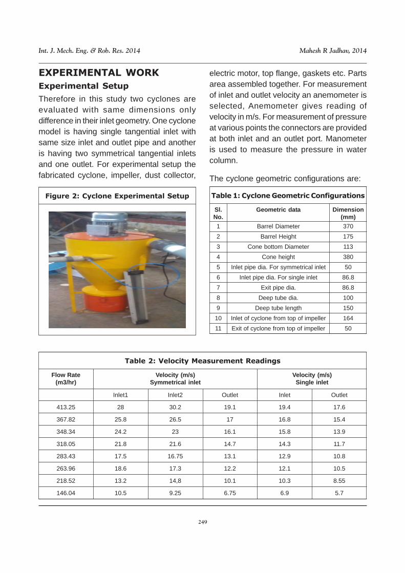
Figure 2: Cyclone Experimental Setup Table 1: Cyclone Geometric Configurations
Sl.No.
1
2
3
4
5
6
7
8
9
10
11
Geometric data
Barrel Diameter
Barrel Height
Cone bottom Diameter
Cone height
Inlet pipe dia. For symmetrical inlet
Inlet pipe dia. For single inlet
Exit pipe dia.
Deep tube dia.
Deep tube length
Inlet of cyclone from top of impeller
Exit of cyclone from top of impeller
The cyclone geometric configurations are:
Dimension(mm)
370
175
113
380
50
86.8
86.8
100
150
164
50
EXPERIMENTAL WORK
Experimental Setup
Therefore in this study two cyclones areevaluated with same dimensions onlydifference in their inlet geometry. One cyclonemodel is having single tangential inlet withsame size inlet and outlet pipe and anotheris having two symmetrical tangential inletsand one outlet. For experimental setup thefabricated cyclone, impeller, dust collector,
electric motor, top flange, gaskets etc. Partsarea assembled together. For measurementof inlet and outlet velocity an anemometer isselected, Anemometer gives reading ofvelocity in m/s. For measurement of pressureat various points the connectors are providedat both inlet and an outlet port. Manometeris used to measure the pressure in watercolumn.
Table 2: Velocity Measurement Readings
Flow Rate(m3/hr)
Velocity (m/s)Symmetrical inlet
Inlet1
28
25.8
24.2
21.8
17.5
18.6
13.2
10.5
Velocity (m/s)Single inlet
413.25
367.82
348.34
318.05
283.43
263.96
218.52
146.04
Inlet2
30.2
26.5
23
21.6
16.75
17.3
14,8
9.25
Outlet
19.1
17
16.1
14.7
13.1
12.2
10.1
6.75
Inlet
19.4
16.8
15.8
14.3
12.9
12.1
10.3
6.9
Outlet
17.6
15.4
13.9
11.7
10.8
10.5
8.55
5.7

250
Int. J. Mech. Eng. & Rob. Res. 2014 Mahesh R Jadhav, 2014
The experimental work is carried on bothcyclone, they are tested for various flow ratesi.e. for various inlet velocity. The variation inflow rate is obtained by changing therotational speed of impeller (motor) by usingVFD.
Measurement of Velocity
Velocity is measured for different 8 cases,and noted as a reading. The velocity readingsheet is given as follow.
Measurement of Pressure Drop
The pressure is measured by usingmanometer, as shown below
Table 3: Pressure Measurement Readings
Flow Rate (m3/hr)
413.25
367.82
348.34
318.05
283.43
263.96
218.52
146.04
Symmetrical inlet
128.8
127.5
98.2
85.76
65.0
41.0
25.5
22.5
Single inlet
220.14
180.21
144.26
112.32
103.46
84.36
60.40
24.46
NUMERICAL MODELING BY CFD
Boundary Conditions and
Computational grids
Following are boundary conditions are givenfor simulation of cyclone.
Table 3: Boundary Conditions for Simulation
Gas phase
Properties Value UnitMaterial
Viscosity of gasDensity of gas
Materialparticle size
Particle densityViscosity of
particle
Air0.0000185
1.142Wheat Flour
0.01561
1.983x10⁻⁵
-kg/mskg/m3
-mm
kg/m3pa.sec
Solid phase
Figure 3: Mesh Model of Cyclone
Figure 4: Mesh Model of Cyclone Top
For CFD analysis we have given threedifferent flow rates, and results are obtainedwhich are as follows

251
Int. J. Mech. Eng. & Rob. Res. 2014 Mahesh R Jadhav, 2014
Table 5: Boundary Conditions and Results
Diameter
Area
Density
volumetricflow rate
Mass flowrate
Velocity
Staticpressure
Totalpressure
∆p
d
m2
kg/m3
m3/hr
m3/s
kg/s
m/s
pa
Pa
Pa
inlet1
0.05
0.001964
1.142
190
0.0528
0.0603
27.08
1019.69
1438.57
1005.68
Case 1
inlet2
0.05
0.001964
1.142
190
0.0528
0.0603
27.07
1024.68
1443.46
1010.57
outlet
0.0875
0.006014
1.142
380
0.1056
0.1205
21.73
-3.11
432.89
inlet1
0.05
0.001964
1.142
140
0.0389
0.0444
19.94
546.39
773.49
540.58
Case 2
inlet2
0.05
0.001964
1.142
140
0.0389
0.0444
19.94
550.25
777.3
544.39
outlet
0.0875
0.006014
1.142
280
0.0778
0.0888
15.97
-1.64
232.91
inlet1
0.05
0.001964
1.142
90
0.0250
0.0286
12.85
222.61
316.84
221.52
Case 3
inlet2
0.05
0.001964
1.142
90
0.0250
0.0286
12.84
224.47
318.68
223.36
outlet
0.0875
0.006014
1.142
180
0.0500
0.0571
10.27
-0.67
95.32
Velocity Plots
Figure 5: Particle Trace Colored byParticle Velocity for 6 & 8 Micron
Particle Size
RESULT AND CONCLUSION
Experimental trial is completed successfullyalso CFD simulation is also done. A smallscale cyclone designed for flour mill isevaluated and following results are obtained.The test was performed on both cyclones atdifferent velocities. The different readings ofvelocity, pressure is given in Table 2 and 3respectively. Below are different graph forcomparison of results of single and symme-
trical inlet cyclone.
From above Figure 7 it is been observedthat the pressure drop is more for single inletcyclone than symmetrical inlet cyclone. Mea-ns the pressure drop is depending on the inletvelocity for the same model. It is observedthat the pressure drop is increases as theinlet velocity increases for same model.
Figure 6: Contours of Velocity Magnitude
Contours of Total Pressure and
Velocity Magnitude for Case 1

252
Int. J. Mech. Eng. & Rob. Res. 2014 Mahesh R Jadhav, 2014
Figure 7: Flow Rate Vs Pressure Drop
Flow rate (m3/hr)
By doing changes at inlet geometry ofcyclone i.e. two symmetrical inlets the flowgets divided in to two parts. The performanceparameters of symmetrical inlet cyclone areoptimum than single inlet cyclone. It alsoproved that as inlet velocity increase thecyclone efficiency also increases for samemodel.
REFERENCES
1. Bernardo S, Peres A P and Mori M (2005),“Computational Study of Cyclone FlowFluid Dynamics using a Different InletSection Angle”, Thermal Engineering(RETERM).
2. Bernardo S, Mori M and W P Martignoni(2006), “Evaluation of Cyclone Geometryand its Influence on its PerformanceParameters by CFD”, Powder Tech-nology.
3. Boysan F, Ayers W H and Swithenbank JA (1982), “Fundamental MathematicalModeling Approach to Cyclone Design”,Institute of Chemical Engineers.
4. Crawford M (1976), “Air Pollution ControlTheory”, McGraw-Hill.
5. L Wang, C B Parneel, B W Shaw and RE Lecay (2006), “A Theoretical Approachfor Predicting Number of Turns andCyclone Pressure Drop.
6. Lapple C E (1951), “Process Use ManyCollector Types”, Chemical Engineering.
7. Lingjuan Wang (2004), “Theoretical Studyof Cyclone Design”, Texas A & MUniversity.
8. Martignoni W P, Bernardo S and QuintaniC L (2005), “Evaluation of GeometricModifications at an Experimental Cycloneusing Computational Fluid Dynamics(CFD)”, Proceedings on 2nd CFD Oil, Riode Janeiro R J.